JP4887103B2 - Method for evaluating conductive roller - Google Patents
Method for evaluating conductive roller Download PDFInfo
- Publication number
- JP4887103B2 JP4887103B2 JP2006235741A JP2006235741A JP4887103B2 JP 4887103 B2 JP4887103 B2 JP 4887103B2 JP 2006235741 A JP2006235741 A JP 2006235741A JP 2006235741 A JP2006235741 A JP 2006235741A JP 4887103 B2 JP4887103 B2 JP 4887103B2
- Authority
- JP
- Japan
- Prior art keywords
- roller
- theta
- conductive
- value
- conductive roller
- Prior art date
- Legal status (The legal status is an assumption and is not a legal conclusion. Google has not performed a legal analysis and makes no representation as to the accuracy of the status listed.)
- Expired - Fee Related
Links
Images


Abstract
Description
本発明は、複写機、プリンター、ファクシミリ等に代表される電子写真装置、静電記録装置などの画像形成装置に使用される導電性ローラ、特に帯電ローラの評価方法に関する。 The present invention is a copying machine, a printer, an electrophotographic device such as a facsimile, a conductive roller used in an image forming apparatus such as an electrostatic recording apparatus, method for evaluating particular charging roller.
従来の電子写真装置において、感光体表面を均一に帯電するための接触帯電装置では、帯電ローラに直流電圧を印加する方式、交流電源と直流電源を同時に印加する方式等により、被帯電体である感光体との間で放電電界を形成し、感光体表面を均一に帯電させている。 In a conventional electrophotographic apparatus, a contact charging device for uniformly charging the surface of a photosensitive member is a member to be charged by a method of applying a DC voltage to a charging roller, a method of simultaneously applying an AC power source and a DC power source, etc. A discharge electric field is formed between the photosensitive member and the surface of the photosensitive member is uniformly charged.
感光体を均一に帯電させるための、帯電ローラの構成としては、鉄やステンレス等の導電性軸体上にゴムや樹脂からなる導電性弾性層を設けることが一般的である。該弾性層には、導電性カーボンブラックや金属粉等の導電性材料が添加されて導電性が付与されると共に、感光体との当接(ニップ幅)を適正にするために適度な弾性が保持させている。弾性の調整には、オイル、可塑剤等の軟化剤が添加されているが、これらの軟化剤は一般に移行性があり、感光体を汚染する場合があるので、必要に応じて表面層が設けられる。 As a configuration of the charging roller for uniformly charging the photosensitive member, a conductive elastic layer made of rubber or resin is generally provided on a conductive shaft body such as iron or stainless steel. A conductive material such as conductive carbon black or metal powder is added to the elastic layer to provide conductivity, and the elastic layer has a suitable elasticity for proper contact (nip width) with the photoreceptor. It is held. For the adjustment of elasticity, softeners such as oil and plasticizer are added, but these softeners are generally migratory and may contaminate the photoreceptor, so a surface layer is provided if necessary. It is done.
このような構成からなる帯電ローラは、接触帯電装置内で、適宜の押し圧力で感光体に押し当てられており、これに電圧が印加されることにより感光体表面を帯電させる。押し当てる機構としては、帯電ローラの両端部にばね等の押し当て手段を設けるのが一般的であり、これによる感光体と帯電ローラとの接触がニップ幅として形成される。 The charging roller having such a configuration is pressed against the photoconductor with an appropriate pressing force in the contact charging device, and a voltage is applied to the photoconductor to charge the surface of the photoconductor. As a pressing mechanism, generally, a pressing means such as a spring is provided at both ends of the charging roller, and contact between the photosensitive member and the charging roller is formed as a nip width.
感光体表面の均一な帯電のためには、帯電ローラが感光体に対して軸方向での変形によりニップ幅を形成し、均一な放電状態を形成することが望ましいが、押し当て力が帯電ローラの両端部から加わるため、帯電ローラに撓みが生じ、そのたわみに伴って帯電ローラの端部ほど変形が大きく、感光体との当接面で形成されるニップ幅は帯電ローラの中央から端部に向かうほど大きく広がり、さらに前記たわみが著しい場合には軸方向中央部において帯電ローラと感光体との接触が損なわれる場合があった。 In order to uniformly charge the surface of the photosensitive member, it is desirable that the charging roller forms a nip width by deformation in the axial direction with respect to the photosensitive member to form a uniform discharge state. Since the charging roller bends and is deformed as the end of the charging roller is deformed, the nip width formed on the contact surface with the photosensitive member is from the center to the end of the charging roller. When the deflection is remarkable, the contact between the charging roller and the photosensitive member may be impaired in the central portion in the axial direction.
帯電ローラと感光体との軸方向におけるニップ幅を均一に得る方法として、帯電ローラの外形を中心部から両端部に向かって漸次減少する、いわゆるクラウン形状に整形する方法がとられる。 As a method of uniformly obtaining the nip width in the axial direction between the charging roller and the photosensitive member, a method of shaping the outer shape of the charging roller into a so-called crown shape in which the outer shape gradually decreases from the central portion toward both ends.
クラウン形状を有する帯電ローラとして、導電性軸体上に成型した弾性抵抗層をクラウン形状に研磨した後、被覆抵抗層を被覆したものが知られている(例えば、特許文献1参照)。 As a charging roller having a crown shape, one in which an elastic resistance layer molded on a conductive shaft body is polished into a crown shape and then covered with a covering resistance layer is known (see, for example, Patent Document 1).
しかしながら、クラウン量が適切であっても、ローラ軸方向に対して全体的に振れや弾性層の偏肉が大きいと感光体との回転運動の際、帯電ローラが1回転する間に感光体とのニップ幅のバラツキが生じ、帯電不良起因による異常画像が発生する。 However, even if the crown amount is appropriate, if the overall deflection in the axial direction of the roller or the elastic layer has a large deviation, the photosensitive member and the photosensitive member are rotated while the charging roller rotates once during the rotational movement of the photosensitive member. Variation in the nip width occurs, and an abnormal image due to defective charging occurs.
さらに、ローラ軸方向に対する振れや弾性層の偏肉が全体的に小さいものであっても、ローラ軸方向に対してバラツキが大きいと感光体に押し当てたときにニップ幅の左右差を生じ、感光体との回転運動による振動でも左右差を生じるといった問題があった。 In addition, even if the deflection in the roller axis direction and the elastic layer unevenness are small overall, if the variation in the roller axis direction is large, a difference in the nip width between the left and right when pressed against the photoconductor is caused. There is also a problem that a difference in right and left is caused even by vibration due to rotational movement with the photosensitive member.
このバラツキによる影響は、接触帯電装置を長期に使用した場合に顕著で初期では正常な画像が得られる場合でも、長期間使用している間に帯電ローラ外周面に付着する紙粉等が帯電ローラ外周面上に不均一に付着することで、帯電不良に起因する異常画像が発生し易くなっていた。
したがって、本発明は、導電性軸体の外周面上に少なくとも1層の被覆層からなる導電性ローラにおいて、感光体等に押し当てて使用する場合にローラの回転時に軸方向やローラ周方向でニップ幅にバラツキが生じることなく、長期間使用しても紙粉等の汚れがローラ外周面上で偏って付着することなく、安定して良質の画像を得ることができる導電性ローラの評価方法を提供することである。 Therefore, the present invention provides a conductive roller composed of at least one coating layer on the outer peripheral surface of the conductive shaft body. When the roller is pressed against a photosensitive member, the roller is rotated in the axial direction or the roller circumferential direction. Evaluation method of a conductive roller that can stably obtain a high-quality image without causing unevenness in the nip width, and even when used for a long period of time, dirt such as paper dust does not adhere unevenly on the outer peripheral surface of the roller . Is to provide.
本発明者らは、上記課題を解決するために鋭意検討し、導電性ローラの振れ、ローラとほぼ平行に置いた真直な棒とのローラ表面との離間距離の中央部と被覆層端部との差が所定の範囲内にあるとき、良好なローラ性状が得られることを見出した。本発明者らは、さらに検討して、本発明にいたった。 The present inventors have intensively studied to solve the above problems, and the center portion of the distance between the run-out of the conductive roller, the distance between the roller surface and a straight bar placed substantially parallel to the roller, and the end portion of the coating layer It was found that good roller properties can be obtained when the difference is within a predetermined range. The present inventors have further studied and arrived at the present invention.
本発明は、真直の測定基準棒に対しほぼ並行に導電性ローラを置き、その測定基準棒とローラの被覆層表面との離間距離Eを両端側(P1、P3)と中央部(P2)でローラ一周分測定し、ローラ回転角θでの測定値をそれぞれE1θ、E3θ、E2θとしたとき、離間距離E1θ、E2θ、E3θそれぞれでローラ一周での最大値、最小値を算出し、その差の最大値を求め、ローラの外周面の振れとし、また、ローラ回転角θでの離間距離差ΔE{=E1θ(またはE3θ)−E2θ}を求め、これらのローラ一周中の最大値と最小値の差を求め、ω値とし、これら振れ及びω値よりローラ性状を評価することを特徴とする導電性ローラの評価方法である。 In the present invention , a conductive roller is placed almost in parallel with a straight measurement reference rod, and the separation distance E between the measurement reference rod and the surface of the coating layer of the roller is set at both ends (P1, P3) and the central portion (P2). Measured for one rotation of the roller, and when the measured values at the roller rotation angle θ are E1θ, E3θ, and E2θ, respectively, the maximum value and the minimum value for one rotation of the roller are calculated for each of the separation distances E1θ, E2θ, and E3θ The maximum value is obtained, and the deviation of the outer peripheral surface of the roller is determined. Further, the difference ΔE {= E1θ (or E3θ) −E2θ} at the roller rotation angle θ is obtained. A method for evaluating a conductive roller is characterized in that a difference is obtained and set as a ω value, and the roller property is evaluated from the runout and the ω value .
なお、該導電性ローラが、そのローラ外周面の振れが50μm以下であり、そのω値が30μm以下であることが好ましい。 In addition, it is preferable that the conductive roller has a deflection of the outer peripheral surface of the roller of 50 μm or less and a ω value of 30 μm or less .
また、該導電性ローラがクラウン形状であり、該離間距離Eを求めたP1、P2及びP3でのローラ外径をそれぞれD1、D2、D3としたときのクラウン量{D2−(D1+D3)/2}が30μm以上500μm以下であることが好ましい。 Further, the conductive roller has a crown shape, and the crown amount {D2− (D1 + D3) / 2 when the roller outer diameters at P1, P2 and P3 for which the separation distance E is obtained are D1, D2 and D3, respectively. } Is preferably 30 μm or more and 500 μm or less .
そして、該導電性ローラが、ローラ表面で測定したマイクロ硬さが30°から85°の範囲にあることが好ましい。 The conductive roller preferably has a micro hardness measured on the roller surface in the range of 30 ° to 85 °.
本発明によれば、感光体等に押し当てて使用される際にローラ回転時に軸方向やローラ周方向でニップ幅にバラツキが生じることなく、長期間使用しても安定して良質の画像を得ることが可能である導電性ローラが提供される。 According to the present invention, when used while being pressed against a photoreceptor, the nip width does not vary in the axial direction or the circumferential direction of the roller when the roller rotates, and a stable and high-quality image can be obtained even when used for a long period of time. A conductive roller is provided that can be obtained.
以下、本発明について詳細に説明する。 Hereinafter, the present invention will be described in detail.
本発明による導電性ローラは、導電性軸体の外周面上に1層以上の導電性被覆層が設けられ、回転させたときの外周面の振れが、軸線方向で50μm以下である。 In the conductive roller according to the present invention, one or more conductive coating layers are provided on the outer peripheral surface of the conductive shaft body, and the deflection of the outer peripheral surface when rotated is 50 μm or less in the axial direction.
導電性ローラの振れが50μmを超える場合、感光体等に押し当てて回転運動させたときのニップ幅が軸方向全面にわたってばらつくために、電子写真装置に組みつけても良好な画像を得ることができない。 When the deflection of the conductive roller exceeds 50 μm, the nip width when it is pressed against a photoreceptor or the like and rotated is varied over the entire surface in the axial direction, so that a good image can be obtained even when assembled in an electrophotographic apparatus. Can not.
そして、ローラとほぼ並行においた測定基準棒とローラの被覆層表面との離間距離Eを両端側(P1、P3)と中央部(P2)でローラ一周分測定し、ローラ回転角θでの測定値をそれぞれE1θ、E3θ、E2θとするとき、そのローラ回転角θでの離間距離差ΔE{=E1θ(またはE3θ)−E2θ}のローラ一周中の最大値と最小値の差(ω値)が30μm以下であることを特徴とする。 Then, the separation distance E between the measurement reference rod and the surface of the coating layer of the roller, which is substantially parallel to the roller, is measured for one round of the roller at both ends (P1, P3) and the central portion (P2), and measured at the roller rotation angle θ. When the values are E1θ, E3θ, and E2θ, respectively, the difference (ω value) between the maximum value and the minimum value during one round of the roller of the separation distance difference ΔE {= E1θ (or E3θ) −E2θ} at the roller rotation angle θ. It is 30 μm or less.
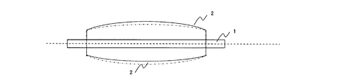
まず、本発明で重要なE1θ、E3θ、E2θの測定方法を図1により説明する。 First, a method for measuring E1θ, E3θ, E2θ, which is important in the present invention, will be described with reference to FIG.
本発明の導電性ローラは、導電性軸体1の周りに、導電性被覆層2が形成されたものであり、その外径はクラウン形状を有していることが好ましい。導電性ローラが導電性軸体1の支点A及びBで支えられている。この導電性ローラにほぼ並行して測定基準棒3が置かれている。導電性ローラの導電性被覆層2の両端からの所定の距離(L)の位置P1およびP3と、中央部P2の位置で、被覆層表面と測定基準棒3の離間距離Eを測定する。次いでローラを所定角回転させて再び離間距離Eを測定する。そのようにして、ローラ一回転分を順次測定する。このときのP1〜P3で測定した離間距離EがそれぞれE1θ、E2θ及びE3θである(なお、θはローラを回転させた角度を意味する)。ここで、回転させる所定角としては、測定回数が多くなることをいとわなければ1°毎とすることも可能であるが、通常10回から15回の測定で済むように設定することが好ましい。
In the conductive roller of the present invention, a
離間距離E1θ〜E3θを用い、離間距離差ΔE(=E1θ(又はE3θ)−E2θ)をローラ回転角毎に算出し、ローラ1周分のうちの最大値と最小値をそれぞれ求める。そして、この最大値と最小値の差をω値とし、ローラの評価における回転に対する指標とする。なお、このω値が30μm以下であることが重要である。 Using the separation distances E1θ to E3θ, the separation distance difference ΔE (= E1θ (or E3θ) −E2θ) is calculated for each roller rotation angle, and the maximum value and the minimum value of one rotation of the roller are obtained. The difference between the maximum value and the minimum value is the ω value, which is an index for rotation in the evaluation of the roller. It is important that this ω value is 30 μm or less.
ω値が30μmを超えた場合、ローラが回転する際に、形状に起因して、図2〜4に示すように軸方向に対して有る特定の位置において偏芯して回転するため、局在的にニップ幅のばらつきが発生する。この場合、上記した振れが50μm以下を満たすものであれば電子写真形成装置に組付けても画出し初期では良好な画像が得られるが、長期間使用するに従って、紙粉等によりローラ表面上に局部的な汚れが発生しやすく、良質な画像が得られなくなる。 When the ω value exceeds 30 μm, when the roller rotates, the roller rotates eccentrically at a specific position with respect to the axial direction as shown in FIGS. In particular, the nip width varies. In this case, a good image can be obtained at the initial stage of image output even if it is mounted on an electrophotographic apparatus as long as the above-mentioned deflection satisfies 50 μm or less. In particular, local stains are likely to occur, and high quality images cannot be obtained.
なお、導電性ローラの被覆層の両端面からP1およびP3までの距離Lはローラ被覆層面長を100としたとき5〜20に相当する任意の距離であることが好ましい。5未満では電子写真形成装置に組付けて使用する際、ローラ軸方向において、画像形成に寄与しない非画像領域に相当する場合があり、本発明では適さない。また、20を超える場合ではP1およびP3の位置が中央部に近すぎるために、ローラ形状の異常が(E1θ−E2θ)および(E3θ−E2θ)で表されるω値に十分反映されず、実画像との相関に乏しいためやはり不適である。 The distance L from both end faces of the coating layer of the conductive roller to P1 and P3 is preferably an arbitrary distance corresponding to 5 to 20 when the roller coating layer surface length is 100. If it is less than 5, it may correspond to a non-image area that does not contribute to image formation in the roller axis direction when used by being assembled in an electrophotographic apparatus, and is not suitable in the present invention. In addition, when the number exceeds 20, the positions of P1 and P3 are too close to the central portion, so that the abnormality of the roller shape is not sufficiently reflected in the ω values represented by (E1θ−E2θ) and (E3θ−E2θ). It is also unsuitable because of poor correlation with images.
本発明における導電性ローラは、感光体等に押し当てられたときに均一なニップ幅を維持するために、該ローラの外径が中央部から両端部に近づくにしたがって漸次減少するようなクラウン形状を有していることが好ましい。その場合、P1、P2及びP3でのローラ外径をそれぞれD1、D2、D3としたとき、ローラのクラウン量{D2−(D1+D3)/2}が30μm以上500μm以下であることが、所望のニップ幅が得られるので好ましい。 The conductive roller according to the present invention has a crown shape in which the outer diameter of the roller gradually decreases from the center to both ends in order to maintain a uniform nip width when pressed against a photoconductor or the like. It is preferable to have. In this case, when the roller outer diameters at P1, P2, and P3 are D1, D2, and D3, respectively, the crown amount {D2- (D1 + D3) / 2} of the roller is 30 μm or more and 500 μm or less. This is preferable because a width can be obtained.
また、本発明における導電性ローラは、硬さは特に制限されないが、ローラ表面のマイクロ硬さが30°以上85°以下であることが、感光体等に押し当てられたときに均一なニップ幅が得やすく、また回転運動の際に感光体等の被当接体表面を損傷することなく長期にわたって使用することが可能となるので好ましい。 In addition, although the hardness of the conductive roller in the present invention is not particularly limited, the roller surface has a micro hardness of 30 ° or more and 85 ° or less so that a uniform nip width when pressed against a photoconductor or the like. This is preferable because it can be used for a long period of time without damaging the surface of the abutted member such as the photosensitive member during the rotational movement.
導電性ローラのマイクロ硬さは、高分子計器株式会社製の硬さ測定器「マイクロ硬度計MD−1型」(商品名)を用いて、23.5℃/60%RH環境において測定したものである。測定方法としては、導電性ローラを金属製の板の上に置き、金属製のブロックにてローラが転がらないように簡単に固定し、測定端子が金属板に対して垂直方向から導電性ローラの中心に正確に当たるようにし、ピークホールドモードで示された値を読み取ることによった。なお、ローラの被覆層端部から30mmの位置(2箇所)及び中央部をそれぞれ周方向に3箇所ずつ、計9箇所を測定し、得られた測定値の平均値を当該ローラのマイクロ硬さとする。 The micro hardness of the conductive roller was measured in a 23.5 ° C./60% RH environment using a hardness meter “Micro Hardness Meter MD-1” (trade name) manufactured by Kobunshi Keiki Co., Ltd. It is. As a measurement method, place the conductive roller on a metal plate, fix it easily with a metal block so that the roller does not roll, and measure the conductive roller from the direction perpendicular to the metal plate. By touching the center exactly and reading the value shown in peak hold mode. In addition, a total of 9 positions were measured at a position (2 places) 30 mm from the edge of the coating layer of the roller and 3 places in the circumferential direction, respectively, and the average value of the obtained measured values was determined as the micro hardness of the roller. To do.
本発明における導電性ローラは、導電性被覆層を有するものであるが、該被覆層が導電性弾性層そのものであったり、導電性弾性層を含む多層であったりすることができる。 The conductive roller in the present invention has a conductive coating layer, but the coating layer may be a conductive elastic layer itself or a multilayer including a conductive elastic layer.
導電性ローラが、導電性弾性層がクラウン形状に形成されたものにあっては、クラウン形状の金型内で形成したものも使用できるが、導電性弾性層を研磨してクラウン形状とすることが好ましい。そのため、軸体両端部をコレットチャックあるいはダイヤフラムチャックで把持固定し、プランジ方式で該ローラの弾性層の外周面を研削する工程を経て形成されることが好ましい。この方法によれば、振れ精度等の形状の調整がしやすく、また長期にわたって精度の維持が可能であるため適している。ローラの形状や精度を調整する方法として、予め所望の形状に加工されたキャビティを有する金型を用いて成型する方法がある。しかし、原料にもよるが成型時の収縮や変形が生じるために形状がばらつく要因となったり、クラウン形状を有するために成型後に型内から取り出すことが困難となったりする。 If the conductive roller has a conductive elastic layer formed in a crown shape, the one formed in a crown-shaped mold can also be used, but the conductive elastic layer should be polished into a crown shape. Is preferred. Therefore, it is preferable that the shaft body is formed through a process of gripping and fixing both end portions of the shaft with a collet chuck or a diaphragm chuck and grinding the outer peripheral surface of the elastic layer of the roller by a plunge method. This method is suitable because it is easy to adjust the shape such as runout accuracy and the accuracy can be maintained over a long period of time. As a method of adjusting the shape and accuracy of the roller, there is a method of molding using a mold having a cavity that has been processed into a desired shape in advance. However, although it depends on the raw material, shrinkage and deformation at the time of molding occur, it causes a variation in shape, and since it has a crown shape, it is difficult to take it out from the mold after molding.
本発明の導電性ローラに使用される導電性軸体としては特に限定されないが、軸体としての強度があり、導電性を有するものが好適である。例えば、鋼鉄製、アルミニウム製、導電性プラスチック製等が挙げられ、中空状、中実状のいずれでも差し支えない。 The conductive shaft used in the conductive roller of the present invention is not particularly limited, but those having strength as a shaft and having conductivity are suitable. For example, steel, aluminum, conductive plastic, etc. may be mentioned, and any of a hollow shape and a solid shape may be used.
また、被覆層を構成する導電性弾性層の材料としては、従来公知のゴムを使用することができる。例えば、ポリブタジエン、天然ゴム、ポリイソプレン、SBR(スチレンブタジエンゴム)、CR(クロロプレンゴム)、EPDM(エチレンプロピレンジエンゴム)、IIR(ブチルゴム)、NBR(アクリロニトリルブタジエンゴム)、シリコーンゴム、ウレタンゴム、エピクロロヒドリンゴム等のゴムや、RB(ブタジエン樹脂)、SBS(スチレン−ブタジエン−スチレンエラストマー)等のポリスチレン系樹脂、ポリオレフィン系樹脂、ポリエステル系樹脂、ポリウレタン、PVC(ポリ塩化ビニル)、アクリル系樹脂、スチレン・酢酸ビニル共重合体、ブタジエン・アクリロニトリル共重合体等の高分子材料に弾性を付与したものを用いることができる。これらの材料は1種で用いても、2種以上を併用しても差し支えない。 Moreover, conventionally well-known rubber can be used as a material of the electroconductive elastic layer which comprises a coating layer. For example, polybutadiene, natural rubber, polyisoprene, SBR (styrene butadiene rubber), CR (chloroprene rubber), EPDM (ethylene propylene diene rubber), IIR (butyl rubber), NBR (acrylonitrile butadiene rubber), silicone rubber, urethane rubber, epi Rubbers such as chlorohydrin rubber, polystyrene resins such as RB (butadiene resin) and SBS (styrene-butadiene-styrene elastomer), polyolefin resins, polyester resins, polyurethane, PVC (polyvinyl chloride), acrylic resins, A polymer material such as a styrene / vinyl acetate copolymer, a butadiene / acrylonitrile copolymer, or the like that has been given elasticity can be used. These materials may be used alone or in combination of two or more.
また、必要に応じて加硫剤を使用しても良い。加硫剤としては使用するゴムの種類により、硫黄系加硫剤、有機過酸化物、キノイド系加硫剤、樹脂架橋剤、金属酸化物架橋剤、アミン架橋剤、トリアジン系架橋剤、マレイミド系架橋剤等の公知の架橋剤適宜選択できる。なお、加硫剤の配合量は適宜決めても差し支えない。なお、この他、加硫促進剤、老化防止剤、可塑剤等を添加してもよい。 Moreover, you may use a vulcanizing agent as needed. Depending on the type of rubber used as the vulcanizing agent, sulfur vulcanizing agent, organic peroxide, quinoid vulcanizing agent, resin crosslinking agent, metal oxide crosslinking agent, amine crosslinking agent, triazine crosslinking agent, maleimide type A known crosslinking agent such as a crosslinking agent can be appropriately selected. The blending amount of the vulcanizing agent may be determined as appropriate. In addition, a vulcanization accelerator, an antiaging agent, a plasticizer, and the like may be added.
導電性弾性層の製造方法は、金型を用いる方法、チューブ状に成形した材料を硬化した後に軸体を圧入する方法、および硬化前の材料を軸体に被覆硬化する方法があり、いずれの方法であっても差し支えない。本発明の導電性ローラは研磨で形成することが望ましいので、所望の外径よりも大きく成形する。なお、外径は所望の外径よりも大きければ特に限定されないが、材料効率やコスト面を考慮すると、所望の外径に対して101%から110%の範囲とすることが望ましい。 The method for producing the conductive elastic layer includes a method using a mold, a method of press-fitting a shaft after curing a tube-shaped material, and a method of covering and curing a material before curing on a shaft. The method can be used. Since the conductive roller of the present invention is desirably formed by polishing, it is formed to be larger than the desired outer diameter. The outer diameter is not particularly limited as long as it is larger than the desired outer diameter. However, considering material efficiency and cost, it is desirable that the outer diameter is in the range of 101% to 110% with respect to the desired outer diameter.
さらに、被覆層を構成する表面層は塗工あるいはシームレスチューブを被覆することによって設けられる。塗工にて該表面層を設ける場合にはポリオールをポリイソシアネート架橋して得られるポリウレタン層を設けることが好ましい。弾性層に可塑剤等を配合した場合、少量染み出した場合でも弾性層の外周上でポリオールとポリイソシアネートを架橋する際にポリイソシアネートにより架橋されて形成したウレタン層から染み出すことを防止できるためである。また、シームレスチューブを設ける場合でも、上記のような染み出しを防止するために架橋性の樹脂であることが好ましい。利用可能な材料としては、例えば、RB(ブタジエン樹脂)、SBS(スチレンーブタジエンースチレンエラストマー)等のポリスチレン系樹脂、ポリオレフィン系樹脂、ポリエステル系樹脂、ポリウレタン、PVC(ポリ塩化ビニル)、アクリル系樹脂、スチレン・酢酸ビニル共重合体、ブタジエン・アクリロニトリル共重合体等の高分子材料がある。これらは、1種または2種以上を併用して使用される。 Furthermore, the surface layer which comprises a coating layer is provided by coat | covering coating or a seamless tube. When the surface layer is provided by coating, it is preferable to provide a polyurethane layer obtained by polyisocyanate crosslinking of a polyol. When a plasticizer or the like is blended into the elastic layer, it can be prevented from oozing out from the urethane layer formed by crosslinking with the polyisocyanate when the polyol and polyisocyanate are cross-linked on the outer periphery of the elastic layer. It is. Even when a seamless tube is provided, it is preferably a crosslinkable resin in order to prevent the above-described bleeding. Examples of usable materials include polystyrene resins such as RB (butadiene resin) and SBS (styrene-butadiene-styrene elastomer), polyolefin resins, polyester resins, polyurethane, PVC (polyvinyl chloride), and acrylic resins. And polymer materials such as styrene / vinyl acetate copolymer and butadiene / acrylonitrile copolymer. These are used alone or in combination of two or more.
弾性層及び表面層には、所望の導電性を得るために導電剤を配合しても良く、イオン導電系の導電剤や電子導電系の導電剤が適宜選択できる。例えば、ポリアニリン、ポリピロール、ポリアセチレン等の導電性ポリマー、トリメチルオクタデシルアンモニウムパークロレート、ベンジルトリメチルアンモニウムクロライド等の第4級アンモニウム塩、過塩素酸リチウム、過塩素酸カリウム等の過塩素酸塩、リン酸エステル、脂肪族アルコールサルフェート塩、脂肪族多価アルコール、イオン系界面活性剤等、グラファイト、スズ、ルテニウム、チタン、ニッケル、銅、銀、ゲルマニウム等の金属及びそれらの酸化物、ケッチェンブラック(商品名)、HAF、SAF、ISAF、SRF、FT等のカーボンブラックなどが使用できる。弾性層及び表面層に使用される高分子材料に分散させる方法としてはロールニーダー、バンバリーミキサー、ボールミル、サンドグラインダー、ペイントシェイカー等を適宜使用すればよい。 In the elastic layer and the surface layer, a conductive agent may be blended in order to obtain desired conductivity, and an ion conductive conductive agent or an electronic conductive conductive agent can be appropriately selected. For example, conductive polymers such as polyaniline, polypyrrole and polyacetylene, quaternary ammonium salts such as trimethyl octadecyl ammonium perchlorate and benzyl trimethyl ammonium chloride, perchlorates such as lithium perchlorate and potassium perchlorate, phosphate esters , Aliphatic alcohol sulfate salts, aliphatic polyhydric alcohols, ionic surfactants, etc., metals such as graphite, tin, ruthenium, titanium, nickel, copper, silver, germanium and their oxides, ketjen black (trade name) ), Carbon black such as HAF, SAF, ISAF, SRF, and FT can be used. As a method for dispersing the polymer material used for the elastic layer and the surface layer, a roll kneader, a Banbury mixer, a ball mill, a sand grinder, a paint shaker, or the like may be used as appropriate.
本発明の導電性ローラは、電子写真装置等の感光体を帯電するのに使用する帯電ローラとして有用である。 The conductive roller of the present invention is useful as a charging roller used to charge a photoreceptor such as an electrophotographic apparatus.
また、上記したE1θ〜E3θを測定し、ω値を求める方法は、ローラの性能評価に有用な評価方法である。 Further, the above-described method for measuring E1θ to E3θ and obtaining the ω value is an evaluation method useful for evaluating the performance of the roller.
次に、本発明について実施例より詳細に説明する。本発明はこれらの例によって何ら限定されるものではない。 Next, the present invention will be described in more detail with reference to examples. The present invention is not limited by these examples.
まず、以下の実施例にて導電性ローラを評価する方法について説明する。
・形状測定
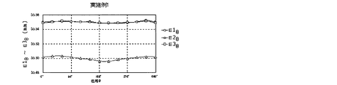
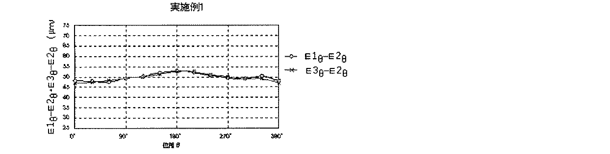
E1θ、E2θ及びE3θの測定は、図1に示すようにして行った。すなわち、導電性ローラ両端部に露出した軸体1の支点A及びBでローラが回転しないように支持して、この軸体1の軸方向に対する中心線とほぼ平行にある測定基準棒3と40mm離間して配置した。この状態で、測定基準棒3ローラ外周面との距離をP1、P2及びP3で測定し、それぞれE10、E20及びE30とした。そして、(E10−E20)及び(E30−E20)を算出した。次にローラを30°回転させて上記と同様に測定し、(E130−E230)及び(E330−E230)を算出した。この作業を順次30°回転させて1周分測定し、(E1θ−E2θ)及び(E3θ−E2θ)に相当する値をそれぞれ12個ずつ、計24個を算出した。そしてこの中から最大値と最小値を選び出し、その差(ω値)を算出し、このω値を元に効果を評価した。なお、実施例1での測定結果を、図6(E1θ〜E3θ)及び図7((E1θ−E2θ)及び(E3θ−E2θ))に示す。
・振れ測定
上記形状測定でE1θ〜E3θを測定したときのE1θ〜E3θのそれぞれついて最大値、最小値を選定し、その差を振れとした。
・マイクロ硬さ
マイクロ硬さは、高分子計器株式会社製の硬さ計「マイクロ硬度計MD−1型」(商品名)にて、23.5℃/60%RH環境において測定した。測定方法としては、導電性ローラを金属製の板の上に置き、金属製のブロックでローラが転がらないように簡単に固定し、測定端子が金属板に対して垂直方向から該ローラの中心に正確に当たるようにし、ピークホールドモードで測定した時の値を読み取った。これを当該ローラの被覆層端部から30mmの位置(2箇所)及び中央部のそれぞれ周方向に3箇所ずつ、計9箇所を測定し、得られた値を平均値してローラのマイクロ硬さとした。
・画像評価
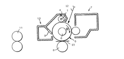
帯電ローラを、ヒューレット・パッカード製の電子写真装置「Color LaserJet 3700」(商品名)の帯電ローラとして組み込み、連続12000枚の耐久を行った。耐久にかける前(初期)、耐久6000枚直後(耐久1)及び耐久12000枚終了後(耐久2)にハーフトーン画像を出力した。得られたハーフトーン画像に表れる帯電不良による異常画像の発生を、下記基準で評価した。なお、帯電ローラには−1500Vの直流電圧を印加し、感光体の周速を100mm/sec.とした。さらに、ここで用いた電子写真装置は図5に示すような構造を有しているものである。
◎:ハーフトーン画像において、帯電不良に起因される黒帯状のムラがない。
○:ハーフトーン画像において、帯電不良に起因される黒帯状のムラがわずかに認められるが、実用上問題ない。
×:ハーフトーン画像において、帯電不良に起因される黒帯状のムラがある。
実施例1
・ゴムローラの製造
エピクロロヒドリンゴム「エピクロマーCG102」(商品名、ダイソー株式会社製)100質量部、酸化亜鉛(2種、ハクスイテック株式会社製)5質量部、ステアリン酸「ステアリン酸S」(商品名、花王株式会社製)1質量部、カーボンブラック「旭#15」(商品名、旭カーボン株式会社製)5質量部、炭酸カルシウム「シルバーW」(商品名、白石工業株式会社製)40質量部、可塑剤「ポリサイザーP−202」(商品名、セバシン酸系ポリエステル、大日本インキ株式会社製)5質量部、イオン導電剤「KS−555」(商品名、第4級アンモニウム塩、花王株式会社製)2質量部、ジベンゾチアジルジサルファイド「ノクセラーDM」(商品名、大内新興化学株式会社製)1質量部、テトラメチルチウラムモノスルフィド「ノクセラーTS」(商品名、大内新興化学株式会社製)1質量部及び硫黄「サルファックス200S」(商品名、鶴見化学株式会社製)1質量部を、密閉型混練機及びオープンロール機を用いて混練を行なうことにより未加硫のゴム組成物を得た。
First, a method for evaluating a conductive roller in the following example will be described.
-Shape measurement The measurement of E1 (theta), E2 (theta), and E3 (theta) was performed as shown in FIG. In other words, the roller is supported by the fulcrums A and B of the shaft body 1 exposed at both ends of the conductive roller so that the roller does not rotate, and the
-Runout measurement The maximum value and the minimum value were selected for each of E1θ to E3θ when E1θ to E3θ were measured in the above shape measurement, and the difference was regarded as the shake.
-Micro hardness Micro hardness was measured in a 23.5 degreeC / 60% RH environment with the hardness meter "micro hardness meter MD-1 type" (brand name) by a polymer instrument company. As a measuring method, place a conductive roller on a metal plate, fix it easily with a metal block so that the roller does not roll, and the measurement terminal is perpendicular to the metal plate from the center of the roller. The value when measured in the peak hold mode was read so that it was correctly hit. This was measured at a total of 9 locations, 30 mm from the edge of the coating layer of the roller (2 locations) and 3 locations in the circumferential direction of the central portion, and the average value was obtained to determine the micro hardness of the roller. did.
Image Evaluation The charging roller was incorporated as a charging roller of an electrophotographic apparatus “Color LaserJet 3700” (trade name) manufactured by Hewlett-Packard, and durability of 12,000 sheets was continuously performed. Halftone images were output before endurance (initial), immediately after endurance of 6000 sheets (endurance 1), and after end of endurance 12000 sheets (endurance 2). The occurrence of abnormal images due to poor charging appearing in the obtained halftone images was evaluated according to the following criteria. A DC voltage of −1500 V was applied to the charging roller, and the peripheral speed of the photosensitive member was 100 mm / sec. It was. Further, the electrophotographic apparatus used here has a structure as shown in FIG.
A: In the halftone image, there is no black belt-like unevenness caused by charging failure.
○: Black band-like unevenness due to charging failure is slightly observed in the halftone image, but there is no practical problem.
X: In a halftone image, there is a black belt-like unevenness caused by charging failure.
Example 1
・ Manufacture of rubber rollers Epichlorohydrin rubber “Epichromer CG102” (trade name, manufactured by Daiso Corporation) 100 parts by mass, zinc oxide (2 types, manufactured by Hakusui Tech Co., Ltd.) 5 parts by mass, stearic acid “stearic acid S” (trade name) 1 part by mass, manufactured by Kao Corporation, 5 parts by mass of carbon black “Asahi # 15” (trade name, manufactured by Asahi Carbon Co., Ltd.), 40 parts by mass of calcium carbonate “Silver W” (trade name, manufactured by Shiraishi Kogyo Co., Ltd.) , 5 parts by mass of plasticizer “Polysizer P-202” (trade name, sebacic acid polyester, manufactured by Dainippon Ink Co., Ltd.), ionic conductive agent “KS-555” (trade name, quaternary ammonium salt,
次いで、クロスヘッドダイを備えた70mm押出し機を用い、未加硫ゴム組成物を円柱状に鋼鉄製軸体と共に押出し該鋼鉄製軸体の周上に未加硫ゴムを被覆した。なお、鋼鉄製軸体は、予め接着剤「メタロックU−20」(商品名、東洋化学研究所株式会社製)を塗布された、直径6mm、長さ250mmの、無電解ニッケルメッキを施したものである。この軸体の両端に被覆された未加硫ゴム層をカッター刃にて両端部各10mm相当部分を除去し、軸体を露出させ、ローラ軸受け部分を作成した。その後、熱風炉にて180℃×1h加熱して、導電性弾性層を有するゴムローラを作成した。
・導電性弾性層の調整
次いで、ローラの両端部に露出した軸体を双方からコレットチャックで把持固定して回転できる機構を備えたNC研削機を使用して、軸方向において中央部から両端に近づくにつれて外径が減少するようなクラウン形状を有するゴムローラを調整した。具体的には、NC研削機の取り付けられている砥石(φ220mm、幅240mm)を逆クラウン状にドレッシングし、ローラ研磨時に砥石の形状を転写することによりローラをクラウン形状とした。クラウン量の調整は砥石をドレッシングする際の逆クラウン量にて調整し、研磨後100μmとなるようにした。また、導電性弾性層の長さが230mmで、軸方向中央部においてφ9.0mmとなるように研磨した。
・表面層の作成
ε−カプロラクトン変性アクリルポリオール溶液(希釈溶剤:MEK(メチルエチルケトン)、固形分20質量%、水酸基価50)100質量部及び導電性酸化スズ20質量部の混合液を、分散メディアがジルコニアビーズ(平均粒径0.5mm)である横型サンドミルを3回通して、分散した。この分散液からビーズを瀘過分離し、ヘキサメチレンジイソシアネート(HDI)をOH/NCO=1.0になるように添加して、表層用塗料を調製した。
Next, using a 70 mm extruder equipped with a crosshead die, the unvulcanized rubber composition was extruded in a cylindrical shape together with a steel shaft body, and the unvulcanized rubber was coated on the periphery of the steel shaft body. The steel shaft was pre-coated with an adhesive "Metaloc U-20" (trade name, manufactured by Toyo Chemical Laboratory Co., Ltd.) and was electroless nickel plated with a diameter of 6 mm and a length of 250 mm. It is. The unvulcanized rubber layer coated on both ends of the shaft body was removed with a cutter blade at portions corresponding to 10 mm at both ends to expose the shaft body, thereby creating roller bearing portions. Then, the rubber roller which has a conductive elastic layer was created by heating 180 degreeC x 1h with a hot air furnace.
-Adjustment of the conductive elastic layer Next, using an NC grinder equipped with a mechanism that can rotate the shaft body exposed at both ends of the roller by gripping and fixing it from both sides with a collet chuck, it is axially moved from the center to both ends. A rubber roller having a crown shape whose outer diameter decreases as it approaches is adjusted. Specifically, a grindstone (φ220 mm, width 240 mm) to which an NC grinder is attached is dressed in a reverse crown shape, and the shape of the grindstone is transferred during roller polishing, so that the roller has a crown shape. The amount of crown was adjusted by the amount of reverse crown when dressing the grindstone so that it became 100 μm after polishing. Further, the conductive elastic layer was polished to have a length of 230 mm and a diameter of 9.0 mm at the center in the axial direction.
-Creation of surface layer ε-Caprolactone-modified acrylic polyol solution (diluent solvent: MEK (methyl ethyl ketone), solid content 20% by mass, hydroxyl value 50) 100 parts by mass and conductive tin oxide 20 parts by mass, dispersion media A horizontal sand mill of zirconia beads (average particle size 0.5 mm) was passed three times for dispersion. The beads were filtered and separated from this dispersion, and hexamethylene diisocyanate (HDI) was added so that OH / NCO = 1.0 to prepare a surface coating composition.
次いで、上記にて表面研磨したゴムローラの導電性弾性層の表面上に表層用塗料を浸漬コートした後、熱風循環乾燥機中、150℃で1時間乾燥して、導電性ローラを得た。なお、乾燥後の表面層(ウレタン層)の厚みは30μmであった。このようにして得られた導電性ローラから、上記の測定したω値が6μmであるものを選択し、帯電ローラAとした。 Subsequently, the surface layer paint was dip coated on the surface of the conductive elastic layer of the rubber roller whose surface was polished as described above, and then dried at 150 ° C. for 1 hour in a hot air circulating dryer to obtain a conductive roller. In addition, the thickness of the surface layer (urethane layer) after drying was 30 μm. From the conductive roller thus obtained, a roller having the above measured ω value of 6 μm was selected as a charging roller A.
得られた帯電ローラAについて、上記した形状、振れ、マイクロ硬さ及び画像評価を行った。これらの結果を表1に示した。なお、形状測定の結果は図6及び図7に示した。 The obtained charging roller A was subjected to the above-described shape, vibration, micro hardness, and image evaluation. These results are shown in Table 1. The shape measurement results are shown in FIGS.
画像評価の結果、初期から非常に良好な画像が得られ、6000枚および12000枚と連続で通紙しても帯電不良起因による画像不良は発生しなかった。この帯電ローラでは表1、図6および図7に示すようにローラ外周面の振れが軸方向全体にわたって小さいために、ローラを回転運動させても常に安定した形状で感光体に押し当てることができるので、均一なニップ幅が安定して得られたと考えられる。
実施例2
実施例1と同様に作成した導電性ローラからω値が15μmで、振れが50μmより小さいが実施例1におけるより大きいものを選択し、帯電ローラBとした。以下、実施例1と同様に形状、振れ、マイクロ硬さ及び画像評価を行った。これらの結果を表1に示した。なお、形状測定の結果は図8及び図9に示した。
As a result of the image evaluation, a very good image was obtained from the beginning, and no image defect due to charging failure occurred even when the sheet was continuously fed through 6000 sheets and 12000 sheets. In this charging roller, as shown in Table 1, FIG. 6, and FIG. 7, since the deflection of the outer peripheral surface of the roller is small over the entire axial direction, it can always be pressed against the photosensitive member in a stable shape even if the roller is rotated. Therefore, it is considered that a uniform nip width was stably obtained.
Example 2
From the conductive roller prepared in the same manner as in Example 1, the ω value was 15 μm and the deflection was less than 50 μm, but the larger one in Example 1 was selected and designated as charging roller B. Hereinafter, in the same manner as in Example 1, shape, vibration, micro hardness, and image evaluation were performed. These results are shown in Table 1. The shape measurement results are shown in FIGS.
画像評価の結果、初期および6000枚通紙後では良好な画像が得られたが、12000枚通紙後では、実用上問題ない程度であるが、わずかに黒帯状のムラが認められた。この帯電ローラBは、振れは軸方向全体にわたってあまり良好でないが、ローラ回転方向に対する各位相で比較すると、ローラ軸方向全体にわたって同じ位相に偏芯していることが分かる。従って、ローラを感光体に押し当てて回転運動させても比較的均一なニップ幅が得られたものであると判断される。
実施例3
実施例1と同様に作成した導電性ローラからω値が29μmで、振れが50μmより小さいが実施例1におけるより大きく、振れ精度のあまりよくないものを選択し、帯電ローラCとした。以下、実施例1と同様に形状、振れ、マイクロ硬さ及び画像評価を行った。これらの結果を表1に示した。なお、形状測定の結果は図10及び図11に示した。
As a result of image evaluation, a good image was obtained at the initial stage and after passing 6000 sheets, but after passing 12,000 sheets, although there was no practical problem, a slight black belt-like unevenness was observed. In this charging roller B, the deflection is not so good over the entire axial direction, but it can be seen that the phase is eccentric to the same phase over the entire roller axial direction when compared with each phase with respect to the roller rotation direction. Therefore, it is determined that a relatively uniform nip width is obtained even when the roller is pressed against the photosensitive member and rotated.
Example 3
A charging roller C was selected from a conductive roller prepared in the same manner as in Example 1 with a ω value of 29 μm and a deflection smaller than 50 μm, but larger than that in Example 1 and with poor deflection accuracy. Hereinafter, in the same manner as in Example 1, shape, vibration, micro hardness, and image evaluation were performed. These results are shown in Table 1. The shape measurement results are shown in FIGS.
画像評価の結果、初期では良好な画像が得られたが、6000枚通紙後および12000枚通紙後では、実用上問題ない程度であるが、わずかに黒帯状のムラが認められた。この帯電ローラCは、振れは中央部で特に大きく、ローラ軸方向にわたってばらつきが見られるが、ローラ回転方向に対する各位相で比較すると、ローラ軸方向全体にわたって同じ位相に偏芯していることが分かる。従って、ローラを感光体に押し当てて回転運動させても比較的均一なニップ幅が得られているが、実施例2と比べ、軸方向において中央部のみで偏芯が大きいため、若干性能が劣っている。
実施例4
実施例1と同様に作成した導電性ローラから、比較的振れ精度は良いが、ω値が29μmと大きかったものを選択し、帯電ローラDとした。以下、実施例1と同様に形状、振れ、マイクロ硬さ及び画像評価を行った。これらの結果を表1に示した。なお、形状測定の結果は図12及び図13に示した。
As a result of the image evaluation, a good image was obtained in the initial stage. After passing through 6,000 sheets and after passing through 12,000 sheets, although there was no practical problem, a slight black belt-like unevenness was observed. In the charging roller C, the deflection is particularly large in the central portion, and variation is observed in the roller axial direction. However, when compared with each phase with respect to the roller rotating direction, it can be seen that the charging roller C is eccentric to the same phase in the entire roller axial direction. . Therefore, a relatively uniform nip width is obtained even when the roller is pressed against the photosensitive member and rotated, but compared with the second embodiment, the eccentricity is large only at the central portion in the axial direction, so that the performance is slightly improved. Inferior.
Example 4
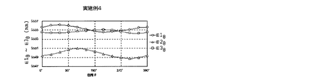
A conductive roller produced in the same manner as in Example 1 with a relatively good runout accuracy but having a large ω value of 29 μm was selected as a charging roller D. Hereinafter, in the same manner as in Example 1, shape, vibration, micro hardness, and image evaluation were performed. These results are shown in Table 1. The shape measurement results are shown in FIGS.
画像評価の結果、初期では良好な画像が得られたが、6000枚通紙後および12000枚通紙後では、実用上問題ない程度であるが、わずかに黒帯状のムラが認められた。この帯電ローラDは、振れは軸方向全体にわたって比較的良好であるが、ローラ回転方向に対する各位相で比較すると、ローラ軸方向全体にわたって僅かであるが位相が偏芯していることが分かる。従って、ローラを感光体に押し当てて回転運動させるとニップ幅が軸方向に対してばらつきが僅かに現れていると思われるが、実用上は問題なく使用できる程度であった。
実施例5
未加硫ゴム組成物として、エピクロロヒドリンゴム「エピクロマーCG102」(商品名)100質量部、酸化亜鉛(2種)5質量部、ステアリン酸「ステアリン酸S」(商品名)1質量部、カーボンブラック「旭#70」(商品名、旭カーボン株式会社製)40質量部、炭酸カルシウム「シルバーW」(商品名)40質量部、イオン導電剤「KS−555」(商品名)2質量部、ジベンゾチアジルジサルファイド「ノクセラーDM」(商品名)1質量部、テトラメチルチウラムモノスルフィド「ノクセラーTS」(商品名)1質量部及び硫黄「サルファックス200S」(商品名)1質量部を実施例1と同様に混練して得たものを使用した。また、クラウン量が48μmとなるように研磨した以外は、実施例1と同様にして導電性ローラを作成した。得られた導電性ローラから、比較的振れ精度は良いが、ω値が23μmであるものを選択して、帯電ローラEとした。以下、実施例1と同様に形状、振れ、マイクロ硬さ及び画像評価を行った。これらの結果を表1に示した。
As a result of the image evaluation, a good image was obtained in the initial stage. After passing through 6,000 sheets and after passing through 12,000 sheets, although there was no practical problem, a slight black belt-like unevenness was observed. In this charging roller D, the deflection is relatively good over the entire axial direction, but when compared with each phase with respect to the roller rotation direction, it can be seen that the phase is decentered although it is slight over the entire roller axial direction. Therefore, when the roller is pressed against the photosensitive member and rotated, the nip width seems to show a slight variation in the axial direction, but it was practically usable without any problem.
Example 5
As an unvulcanized rubber composition, epichlorohydrin rubber “Epichromer CG102” (trade name) 100 parts by mass, zinc oxide (2 types) 5 parts by mass, stearic acid “stearic acid S” (trade name) 1 part by mass, carbon Black “Asahi # 70” (trade name, manufactured by Asahi Carbon Co., Ltd.) 40 parts by mass, calcium carbonate “Silver W” (trade name) 40 parts by mass, ionic conductive agent “KS-555” (trade name) 2 parts by mass, Example 1 part by weight of dibenzothiazyl disulfide “Noxeller DM” (trade name), 1 part by weight of tetramethylthiuram monosulfide “Noxeller TS” (trade name) and 1 part by weight of sulfur “Sulfax 200S” (trade name) What was obtained by kneading in the same manner as in No. 1 was used. Further, a conductive roller was prepared in the same manner as in Example 1 except that the polishing was performed so that the crown amount was 48 μm. From the obtained conductive roller, a roller having a relatively good deflection accuracy but having a ω value of 23 μm was selected as a charging roller E. Hereinafter, in the same manner as in Example 1, shape, vibration, micro hardness, and image evaluation were performed. These results are shown in Table 1.
画像評価の結果、初期から非常に良好な画像が得られ、6000枚及び12000枚と連続で通紙しても帯電不良起因による画像不良は発生しなかった。従って、高硬度で、かつ、均一なニップ幅を得るためにクラウン量を小さくしても、本発明の評価方法で導電性ローラを判定することが可能である。
実施例6
未加硫ゴム組成物として、エピクロロヒドリンゴム「エピクロマーCG102」(商品名)100質量部、酸化亜鉛(2種)5質量部、ステアリン酸「ステアリン酸S」(商品名)1質量部、カーボンブラック「サーマックスMT N990」(商品名、Can Carb製)5質量部、炭酸カルシウム「シルバーW」(商品名)30質量部、可塑剤「ポリサイザーP−202」(商品名、セバシン酸系ポリエステル)15質量部、イオン導電剤「KS−555」(商品名、第4級アンモニウム塩)2質量部、ジベンゾチアジルジサルファイド「ノクセラーDM」(商品名)1質量部、テトラメチルチウラムモノスルフィド「ノクセラーTS」(商品名)1質量部及び硫黄「サルファックス200S」(商品名)1質量部を実施例1と同様に混練して得たものを使用した。また、クラウン量が220μmとなるように研磨した以外は、実施例1と同様にして導電性ローラを作成した。得られた導電性ローラから、比較的振れ精度は良いが、ω値が27μmであるものを選択して、帯電ローラFとした。以下、実施例1と同様に形状、振れ、マイクロ硬さ及び画像評価を行った。これらの結果を表1に示した。
As a result of the image evaluation, a very good image was obtained from the beginning, and no image defect due to charging failure occurred even when the sheet was continuously fed through 6000 sheets and 12000 sheets. Therefore, even if the crown amount is reduced in order to obtain a high hardness and uniform nip width, the conductive roller can be determined by the evaluation method of the present invention.
Example 6
As an unvulcanized rubber composition, epichlorohydrin rubber “Epichromer CG102” (trade name) 100 parts by mass, zinc oxide (2 types) 5 parts by mass, stearic acid “stearic acid S” (trade name) 1 part by mass, carbon Black "Thermax MT N990" (trade name, manufactured by Can Carb) 5 parts by mass, calcium carbonate "Silver W" (trade name) 30 parts by mass, plasticizer "Polysizer P-202" (trade name, sebacic acid polyester) 15 parts by weight, 2 parts by weight of ionic conductive agent “KS-555” (trade name, quaternary ammonium salt), 1 part by weight of dibenzothiazyl disulfide “Noxeller DM” (trade name), tetramethylthiuram monosulfide “Noxeller” 1 part by weight of “TS” (trade name) and 1 part by weight of “Sulfax 200S” (trade name) were mixed in the same manner as in Example 1. Was used was obtained. Further, a conductive roller was prepared in the same manner as in Example 1 except that the crown was polished so as to have a thickness of 220 μm. From the obtained conductive roller, a roller having a relatively good deflection accuracy but having an ω value of 27 μm was selected as a charging roller F. Hereinafter, in the same manner as in Example 1, shape, vibration, micro hardness, and image evaluation were performed. These results are shown in Table 1.
画像評価の結果、初期から非常に良好な画像が得られ、6000枚及び12000枚と連続で通紙しても帯電不良起因による画像不良は発生しなかった。従って、低硬度でかつ、均一なニップ幅を得るためにクラウン量を大きくしても、本発明の評価方法で導電性ローラを判定することが可能である。
比較例1〜3
導電性弾性層を研磨する際にコレットチャックの軸体把持部にわざとゴミケバ(市販のティッシュペーパー)を付着させた以外は実施例1と同様に導電性ローラを作成した。作成した導電性ローラから、振れが比較的良好なものの中から作成したから、ω値が30μmを超えたものを抜き出して、帯電ローラG(ω値33μm、比較例1)、帯電ローラH(ω値37μm、比較例2)及び帯電ローラI(ω値42μm、比較例3)とした。以下、実施例1と同様に形状、振れ、マイクロ硬さ及び画像評価を行った。これらの結果を表1に示した。なお、形状測定の結果はそれぞれ図14と図15、図16と図17及び図18と図19に示した。
As a result of the image evaluation, a very good image was obtained from the beginning, and no image defect due to charging failure occurred even when the sheet was continuously fed through 6000 sheets and 12000 sheets. Therefore, even if the crown amount is increased in order to obtain a low hardness and uniform nip width, the conductive roller can be determined by the evaluation method of the present invention.
Comparative Examples 1-3
A conductive roller was prepared in the same manner as in Example 1 except that when the conductive elastic layer was polished, a dust mark (commercially available tissue paper) was intentionally attached to the shaft gripping portion of the collet chuck. Since the produced conductive rollers were produced from those having relatively good runout, those having an ω value exceeding 30 μm were extracted, charged roller G (ω value 33 μm, Comparative Example 1), and charged roller H (ω The value was 37 μm, Comparative Example 2) and the charging roller I (ω value 42 μm, Comparative Example 3). Hereinafter, in the same manner as in Example 1, shape, vibration, micro hardness, and image evaluation were performed. These results are shown in Table 1. The shape measurement results are shown in FIGS. 14 and 15, FIGS. 16 and 17, and FIGS. 18 and 19, respectively.
画像評価の結果、各ローラとも初期では実用上問題ない画像が得られたが、6000枚通紙後および12000枚通紙後では、黒帯状のムラが認められた。これらの帯電ローラは振れが比較的小さいにも関わらず、いずれの場合もローラ軸方向全体においてばらばらの位相に偏芯していることが分かる。従って、初期では振れが小さいために比較的良好な画像が得られたが、偏芯が大きいためにニップ幅のばらつきが生じ、長時間回転させるとローラ表面に紙粉等の汚れが局部的に溜まり、画像上欠陥が生じたものである。
比較例4
実施例1と同様に作成した導電性ローラからω値が22μmと良好であるが、振れが50μmを超えるものを選択し、帯電ローラJとした。以下、実施例1と同様に形状、振れ、マイクロ硬さ及び画像評価を行った。これらの結果を表1に示した。なお、形状測定の結果は図20及び図21に示した。
As a result of image evaluation, an image having no practical problem was obtained at the initial stage for each roller, but black belt-like unevenness was observed after passing 6000 sheets and after passing 12,000 sheets. It can be seen that these charging rollers are eccentric to a disparate phase in the entire roller axial direction in spite of relatively small fluctuations. Therefore, a relatively good image was obtained because the shake was small in the initial stage, but due to the large eccentricity, the nip width varied, and when rotated for a long period of time, dirt such as paper dust was localized on the roller surface. That is, the image is defective.
Comparative Example 4
A conductive roller prepared in the same manner as in Example 1 having a good ω value of 22 μm but having a deflection exceeding 50 μm was selected as a charging roller J. Hereinafter, in the same manner as in Example 1, shape, vibration, micro hardness, and image evaluation were performed. These results are shown in Table 1. The results of the shape measurement are shown in FIGS.
画像評価の結果、初期から帯電不良に起因される画像欠陥が認められた。この場合、ローラ軸方向全体において同じ位相に偏芯しているために軸方向に対してのニップ幅のばらつきは比較的小さいと思われるが、全体的に振れが大きいため、正常な画像が得られなかった。 As a result of image evaluation, an image defect caused by a charging failure was recognized from the beginning. In this case, the variation in the nip width in the axial direction seems to be relatively small because the same phase is deviated in the entire roller axial direction, but a normal image is obtained because the overall shake is large. I couldn't.
1 導電性軸体
2 導電性被覆層
3 測定基準棒
4 帯電ローラ
5 感光体
6 基体
7 現像機
8 転写ローラ
9 クリーニングブレード
10 プロセスカートリッジ
11 定着機
12 レーザビーム(情報の書き込み)
13 転写部材(紙)
DESCRIPTION OF SYMBOLS 1
13 Transfer member (paper)
Claims (4)
離間距離E1θ、E2θ、E3θそれぞれでローラ一周での最大値、最小値を算出し、その差の最大値を求め、ローラの外周面の振れとし、また、
ローラ回転角θでの離間距離差ΔE{=E1θ(またはE3θ)−E2θ}を求め、これらのローラ一周中の最大値と最小値の差を求め、ω値とし、
これら振れ及びω値よりローラ性状を評価する
ことを特徴とする導電性ローラの評価方法。 A conductive roller is placed almost parallel to a straight measurement reference rod, and the distance E between the measurement reference rod and the surface of the coating layer of the roller is measured for one round of the roller at both ends (P1, P3) and the central portion (P2). When the measured values at the roller rotation angle θ are E1θ, E3θ, and E2θ, respectively,
Calculate the maximum value and minimum value for one rotation of the roller at each of the separation distances E1θ, E2θ, E3θ, obtain the maximum value of the difference, and determine the runout of the outer peripheral surface of the roller.
The separation distance difference ΔE {= E1θ (or E3θ) −E2θ} at the roller rotation angle θ is obtained, the difference between the maximum value and the minimum value in one round of these rollers is obtained, and the ω value is obtained.
A method for evaluating a conductive roller, characterized in that the roller property is evaluated based on the deflection and the ω value.
Priority Applications (1)
| Application Number | Priority Date | Filing Date | Title |
|---|---|---|---|
| JP2006235741A JP4887103B2 (en) | 2006-08-31 | 2006-08-31 | Method for evaluating conductive roller |
Applications Claiming Priority (1)
| Application Number | Priority Date | Filing Date | Title |
|---|---|---|---|
| JP2006235741A JP4887103B2 (en) | 2006-08-31 | 2006-08-31 | Method for evaluating conductive roller |
Publications (3)
| Publication Number | Publication Date |
|---|---|
| JP2008058633A JP2008058633A (en) | 2008-03-13 |
| JP2008058633A5 JP2008058633A5 (en) | 2009-10-15 |
| JP4887103B2 true JP4887103B2 (en) | 2012-02-29 |
Family
ID=39241435
Family Applications (1)
| Application Number | Title | Priority Date | Filing Date |
|---|---|---|---|
| JP2006235741A Expired - Fee Related JP4887103B2 (en) | 2006-08-31 | 2006-08-31 | Method for evaluating conductive roller |
Country Status (1)
| Country | Link |
|---|---|
| JP (1) | JP4887103B2 (en) |
Families Citing this family (2)
| Publication number | Priority date | Publication date | Assignee | Title |
|---|---|---|---|---|
| US20120251171A1 (en) | 2011-03-29 | 2012-10-04 | Canon Kabushiki Kaisha | Conductive member |
| JP6067632B2 (en) * | 2013-11-21 | 2017-01-25 | 三星電子株式会社Samsung Electronics Co.,Ltd. | Charging member |
Family Cites Families (4)
| Publication number | Priority date | Publication date | Assignee | Title |
|---|---|---|---|---|
| JP3392021B2 (en) * | 1997-11-05 | 2003-03-31 | キヤノン株式会社 | Process cartridge and image forming apparatus |
| JP2000206762A (en) * | 1999-01-11 | 2000-07-28 | Canon Inc | Charging roller, process cartridge and image forming device |
| JP2006029390A (en) * | 2004-07-13 | 2006-02-02 | Canon Inc | Method of manufacturing elastic roller |
| JP2006163147A (en) * | 2004-12-09 | 2006-06-22 | Canon Inc | Electrifying roller, electrifying method, process cartridge and electrophotographic device |
-
2006
- 2006-08-31 JP JP2006235741A patent/JP4887103B2/en not_active Expired - Fee Related
Also Published As
| Publication number | Publication date |
|---|---|
| JP2008058633A (en) | 2008-03-13 |
Similar Documents
| Publication | Publication Date | Title |
|---|---|---|
| KR101488865B1 (en) | Cleaning member for image forming apparatus, charging device, unit for image forming apparatus, process cartridge, and image forming apparatus | |
| KR101453238B1 (en) | Charging member, process cartridge, and electrophotographic apparatus | |
| KR101533751B1 (en) | Cleaning member for image forming apparatus, charging device, unit for image forming apparatus, process cartridge, and image forming apparatus | |
| KR101533750B1 (en) | Cleaning member for image forming apparatus, charging device, unit for image forming apparatus, process cartridge, and image forming apparatus | |
| WO2013108308A1 (en) | Electrophotography roller and method for producing same | |
| JP2008209488A (en) | Charging device, process cartridge and image forming apparatus | |
| JP2012008493A (en) | Cleaning device, charging device, process cartridge for image forming device and image forming method | |
| JP5159156B2 (en) | Charging member, process cartridge, and electrophotographic apparatus | |
| JP4887103B2 (en) | Method for evaluating conductive roller | |
| JP5173247B2 (en) | Charging member, process cartridge, and electrophotographic apparatus | |
| JP4730058B2 (en) | Image forming apparatus and process cartridge | |
| JP2006251008A (en) | Charging member, process cartridge and image forming apparatus | |
| US8565648B2 (en) | Charge element, process cartridge, and image forming apparatus | |
| JP2007163574A (en) | Conductive rubber roller | |
| EP4184026A1 (en) | Conductive roll, image forming apparatus, and inspection method for conductive roll | |
| JP5365732B2 (en) | Charging device, process cartridge, and image forming apparatus | |
| JP2003207967A (en) | Roller for electrophotography and image forming apparatus | |
| JP2009300899A (en) | Evaluation method for conductive member, conductive member, process cartridge, and image forming apparatus | |
| JP2007163786A (en) | Conductive roller, manufacturing method therefor, electrophotographic process cartridge, and image forming apparatus | |
| JP6477119B2 (en) | Cleaning structure, charging device, assembly, and image forming apparatus | |
| JP5145846B2 (en) | Charging device, process cartridge, and image forming apparatus | |
| JP2009199027A (en) | Charging device, process cartridge having the same, and image forming apparatus having the process cartridge | |
| JP2008107622A (en) | Conductive roller and method for manufacturing the same | |
| JP2009080369A (en) | Charging roll | |
| CN115997174A (en) | Conductive roller, image forming apparatus, and detection method for conductive roller |
Legal Events
| Date | Code | Title | Description |
|---|---|---|---|
| A521 | Request for written amendment filed |
Free format text: JAPANESE INTERMEDIATE CODE: A523 Effective date: 20090828 |
|
| A621 | Written request for application examination |
Free format text: JAPANESE INTERMEDIATE CODE: A621 Effective date: 20090828 |
|
| A131 | Notification of reasons for refusal |
Free format text: JAPANESE INTERMEDIATE CODE: A131 Effective date: 20110928 |
|
| A977 | Report on retrieval |
Free format text: JAPANESE INTERMEDIATE CODE: A971007 Effective date: 20110928 |
|
| A521 | Request for written amendment filed |
Free format text: JAPANESE INTERMEDIATE CODE: A523 Effective date: 20111115 |
|
| TRDD | Decision of grant or rejection written | ||
| A01 | Written decision to grant a patent or to grant a registration (utility model) |
Free format text: JAPANESE INTERMEDIATE CODE: A01 Effective date: 20111206 |
|
| A01 | Written decision to grant a patent or to grant a registration (utility model) |
Free format text: JAPANESE INTERMEDIATE CODE: A01 |
|
| A61 | First payment of annual fees (during grant procedure) |
Free format text: JAPANESE INTERMEDIATE CODE: A61 Effective date: 20111212 |
|
| FPAY | Renewal fee payment (event date is renewal date of database) |
Free format text: PAYMENT UNTIL: 20141216 Year of fee payment: 3 |
|
| R150 | Certificate of patent or registration of utility model |
Ref document number: 4887103 Country of ref document: JP Free format text: JAPANESE INTERMEDIATE CODE: R150 Free format text: JAPANESE INTERMEDIATE CODE: R150 |
|
| S111 | Request for change of ownership or part of ownership |
Free format text: JAPANESE INTERMEDIATE CODE: R313113 |
|
| R350 | Written notification of registration of transfer |
Free format text: JAPANESE INTERMEDIATE CODE: R350 |
|
| LAPS | Cancellation because of no payment of annual fees |