JP4886816B2 - Compound switch - Google Patents
Compound switch Download PDFInfo
- Publication number
- JP4886816B2 JP4886816B2 JP2009133299A JP2009133299A JP4886816B2 JP 4886816 B2 JP4886816 B2 JP 4886816B2 JP 2009133299 A JP2009133299 A JP 2009133299A JP 2009133299 A JP2009133299 A JP 2009133299A JP 4886816 B2 JP4886816 B2 JP 4886816B2
- Authority
- JP
- Japan
- Prior art keywords
- contact
- contacts
- pair
- main
- switch
- Prior art date
- Legal status (The legal status is an assumption and is not a legal conclusion. Google has not performed a legal analysis and makes no representation as to the accuracy of the status listed.)
- Active
Links
Images


Classifications
-
- H—ELECTRICITY
- H01—ELECTRIC ELEMENTS
- H01H—ELECTRIC SWITCHES; RELAYS; SELECTORS; EMERGENCY PROTECTIVE DEVICES
- H01H89/00—Combinations of two or more different basic types of electric switches, relays, selectors and emergency protective devices, not covered by any single one of the other main groups of this subclass
-
- H—ELECTRICITY
- H01—ELECTRIC ELEMENTS
- H01H—ELECTRIC SWITCHES; RELAYS; SELECTORS; EMERGENCY PROTECTIVE DEVICES
- H01H13/00—Switches having rectilinearly-movable operating part or parts adapted for pushing or pulling in one direction only, e.g. push-button switch
- H01H13/50—Switches having rectilinearly-movable operating part or parts adapted for pushing or pulling in one direction only, e.g. push-button switch having a single operating member
- H01H13/64—Switches having rectilinearly-movable operating part or parts adapted for pushing or pulling in one direction only, e.g. push-button switch having a single operating member wherein the switch has more than two electrically distinguishable positions, e.g. multi-position push-button switches
-
- H—ELECTRICITY
- H01—ELECTRIC ELEMENTS
- H01H—ELECTRIC SWITCHES; RELAYS; SELECTORS; EMERGENCY PROTECTIVE DEVICES
- H01H19/00—Switches operated by an operating part which is rotatable about a longitudinal axis thereof and which is acted upon directly by a solid body external to the switch, e.g. by a hand
- H01H19/001—Thumb wheel switches
- H01H19/003—Thumb wheel switches having a pushbutton actuator
Landscapes
- Switches With Compound Operations (AREA)
- Rotary Switch, Piano Key Switch, And Lever Switch (AREA)
Abstract
Description
本発明は、押圧操作を検出するプッシュスイッチ部と回転操作を検出するロータリスイッチ部とを備えると共に、前記プッシュスイッチ部が、押圧操作により弾性変形する接点板と、この接点板の弾性変形により該接点板に接触して導通状態に達する被接触接点とを備えて構成され、前記ロータリスイッチ部が、レバーの操作によって軸芯の周りで回転する回転導体に複数の接触子を形成したブラシユニットと、複数の前記接触子に導通可能な複数の固定接点とを備えて構成されている複合スイッチに関する。 The present invention includes a push switch portion that detects a pressing operation and a rotary switch portion that detects a rotation operation, and the push switch portion is elastically deformed by a pressing operation, and the contact plate is elastically deformed by the elastic deformation. A brush unit that includes a contact point that contacts a contact plate and reaches a conductive state, wherein the rotary switch unit has a plurality of contacts formed on a rotating conductor that rotates around an axis by operation of a lever; Further, the present invention relates to a composite switch that includes a plurality of fixed contacts that can conduct to the plurality of contacts.
上記のように構成された複合スイッチとして特許文献1は、下側の本体と上側のフレームとを備え、フレーム中央の孔部に露出する位置にプッシュスイッチを配置し、本体とフレームとの中間から側方に張り出すレバーを備えた構造を有している。本体上面の中央位置にはプッシュスイッチ用の複数の固定接点を備え、この固定接点の上部位置には押圧力によって弾性変形して固定電極を導通させる電極板を備えている。また、本体上面において中心位置から等距離となる位置にロータリスイッチ用の複数の固定接点を備え、これに接触可能な複数の接触子を有した環状のブラシを備え、このブラシを前記レバーに連係している。 As a composite switch configured as described above, Patent Document 1 includes a lower main body and an upper frame, and a push switch is disposed at a position exposed in a hole in the center of the frame, from the middle between the main body and the frame. It has a structure with a lever protruding to the side. A plurality of fixed contacts for push switches are provided at a central position on the upper surface of the main body, and an electrode plate that is elastically deformed by a pressing force to conduct the fixed electrodes is provided at an upper position of the fixed contacts. In addition, a plurality of fixed contacts for the rotary switch are provided at positions equidistant from the center position on the upper surface of the main body, and an annular brush having a plurality of contactors capable of contacting with the fixed contacts is provided, and this brush is linked to the lever. is doing.
このような構成から、プッシュスイッチ部に圧力操作が作用した場合には、電極板の変形によりプッシュスイッチ用の固定電極が導通状態に達し、この押圧操作が検出される。また、レバーに回転操作力が作用した場合には、ブラシの複数の接触子がロータリスイッチ用の固定電極に対して選択的に接触することにより、右回転方向と左回転方向との回転操作を2段階で検出される。 With such a configuration, when a pressure operation is applied to the push switch portion, the push switch fixed electrode reaches a conductive state due to deformation of the electrode plate, and this pressing operation is detected. In addition, when a rotational operation force is applied to the lever, the plurality of contact elements of the brush selectively come into contact with the fixed electrode for the rotary switch, so that the rotation operation in the right rotation direction and the left rotation direction can be performed. It is detected in two stages.
特に、この特許文献1では、ロータリスイッチ用の固定接点として、単一の共通接点と、右回転を検出する2つの個別接点と、左回転を検出する2つの固定接点とを有し、ブラシには、環状の固定部に対して4つの接触子を備えた構造を有し、この4つの接触子は前述した右回転を検出する2つの個別接点と、左回転を検出する2つの個別接点に対応している。 In particular, this Patent Document 1 has a single common contact, two individual contacts for detecting right rotation, and two fixed contacts for detecting left rotation as fixed contacts for the rotary switch. Has a structure with four contacts with respect to the annular fixed part, and these four contacts have two individual contacts for detecting the right rotation and two individual contacts for detecting the left rotation. It corresponds.
このような構成から、ブラシが中立位置から右方向に回転操作された場合には、右回転を検出する2つの個別接点に対して、対応する接触子が順次接触し、この接触時には左回転を検出する接触子の1つが共通接点と接触する状態が維持される。これとは逆に、ブラシが中立位置から左方向に回転操作された場合には、左回転を検出する2つの個別接点に対して、対応する接触子が順次接触し、この接触時には右回転を検出する接触子の1つが共通接点と接触する状態が維持される。これにより、レバーの回転操作を右方向と左方向とにおいて2段に検出できるものとなる。 With such a configuration, when the brush is rotated to the right from the neutral position, the corresponding contacts sequentially contact the two individual contacts that detect the right rotation. A state in which one of the detected contacts is in contact with the common contact is maintained. On the contrary, when the brush is rotated leftward from the neutral position, the corresponding contact contacts the two individual contacts that detect the left rotation sequentially, and at this time, the right rotation is performed. A state in which one of the detected contacts is in contact with the common contact is maintained. Thereby, the rotation operation of the lever can be detected in two steps in the right direction and the left direction.
特許文献1に記載される構成のものでは、ブラシに対して4つの接触子を形成し、これに対応する位置に複数の固定接点(個別接点と共通接点)を配置する構成であるため、複数の固定接点を回転中心の基準とする円周状の広い領域に配置する構成となる。また、回転操作においては適度のピッチで回転操作の回転角度を検出できるように、複数の固定接点同士の間隔(中心を基準とする周方向での間隔)を比較的大きい値に設定する必要がある。このような理由から複数の固定接点は、円周状の広い領域に分散して配置されることになり複合スイッチの小型化を制限するものであった。 In the configuration described in Patent Document 1, four contacts are formed on the brush, and a plurality of fixed contacts (individual contacts and common contacts) are arranged at positions corresponding to the contacts. The fixed contacts are arranged in a wide circumferential area with the rotation center as a reference. Further, in the rotation operation, it is necessary to set the interval between the plurality of fixed contacts (interval in the circumferential direction with respect to the center) to a relatively large value so that the rotation angle of the rotation operation can be detected at an appropriate pitch. is there. For these reasons, the plurality of fixed contacts are distributed in a wide circumferential area, which limits the downsizing of the composite switch.
本発明の目的は、押圧操作の検出が可能で、所定方向と逆方向との回転操作を2段階での検出が可能な複合スイッチを小型に構成する点ある。 An object of the present invention is to form a compact switch that can detect a pressing operation and can detect a rotation operation in a predetermined direction and a reverse direction in two stages.
本発明の特徴は、押圧操作を検出するプッシュスイッチ部と回転操作を検出するロータリスイッチ部とを備えると共に、前記プッシュスイッチ部が、押圧操作により弾性変形する接点板と、この接点板の弾性変形により該接点板に接触して導通状態に達する被接触接点とを備えて構成され、前記ロータリスイッチ部が、レバーの操作によって軸芯の周りで回転する回転導体に複数の接触子を形成したブラシユニットと、複数の前記接触子に導通可能な複数の固定接点とを備えて構成されている複合スイッチであって、
前記ブラシユニットの接触子として、隣接配置される一対の主接触子と、単一の副接触子とを前記軸芯を中心とする同一円周上に備え、
前記固定接点として、前記ブラシユニットが中立姿勢にある際に一対の前記主接触子が同時に接触する主接点と、この中立姿勢において前記副接触子を周方向から挟む位置に離間して配置される一対の第1接点と、この中立姿勢において前記主接点を周方向から挟む位置に離間して配置される一対の第2接点とを備え、
前記ブラシユニットが前記中立姿勢から正方向に回転した際には、一対の前記主接触子の一方が前記主接点に接触する状態で前記副接触子が一対の前記第1接点のうち正回転方向側のものに接触し、更に回転した際には、一対の前記主接触子の一方が前記主接点に接触する状態で一対の前記主接触子の他方が一対の前記第2接点のうち正回転方向側のものに接触し、
前記ブラシユニットが前記中立姿勢から逆方向に回転した際には、一対の前記主接触子の他方が前記主接点に接触する状態で前記副接触子が一対の前記第1接点のうち逆回転方向側のものに接触し、更に回転した際には、一対の前記主接触子の他方が前記主接点に接触する状態で一対の前記主接触子の一方が一対の前記第2接点のうち逆回転方向側のものに接触するように、接触子と固定接点とが配置され、
前記レバーが配置される開放部が、スイッチ本体に前記軸芯を中心とする扇状に形成され、前記主接点と、前記第1接点と、前記第2接点とが、前記開放部の扇状の領域を避けた位置に配置されると共に、前記ブラシユニットの前記主接触子と、前記副接触子とが前記開放部の扇状の領域を避けた位置に配置されている点にある。
A feature of the present invention is that it includes a push switch portion that detects a pressing operation and a rotary switch portion that detects a rotation operation, and the push switch portion is elastically deformed by the pressing operation, and an elastic deformation of the contact plate. And a contacted contact that comes into contact with the contact plate to reach a conductive state, and the rotary switch portion has a plurality of contacts formed on a rotating conductor that rotates around an axis by operation of a lever. A composite switch configured to include a unit and a plurality of fixed contacts that can conduct to the plurality of contacts,
As a contact of the brush unit, a pair of adjacent main contacts and a single sub-contact are provided on the same circumference centered on the axis,
As the fixed contact, when the brush unit is in a neutral posture, a pair of the main contacts are simultaneously contacted, and in this neutral posture, they are spaced apart from each other so as to sandwich the sub contact from the circumferential direction. A pair of first contacts, and a pair of second contacts that are spaced apart at a position sandwiching the main contact from the circumferential direction in this neutral posture,
When the brush unit is rotated in the forward direction from the neutral posture, the sub-contact is in the positive rotation direction of the pair of first contacts while one of the pair of main contacts is in contact with the main contact. When one of the pair of main contacts contacts the main contact, the other of the pair of main contacts rotates forward of the pair of second contacts. Touch the directional side,
When the brush unit is rotated in the reverse direction from the neutral posture, the sub-contact is in the reverse rotation direction of the pair of first contacts while the other of the pair of main contacts is in contact with the main contact. One of the pair of main contacts is reversely rotated out of the pair of second contacts while the other of the pair of main contacts is in contact with the main contact. The contact and the fixed contact are arranged so as to contact the direction side ,
The open portion in which the lever is disposed is formed in a fan shape centered on the shaft core in the switch body, and the main contact, the first contact, and the second contact are fan-shaped regions of the open portion. The main contact and the sub-contact of the brush unit are arranged at a position avoiding the fan-shaped region of the open portion .
この構成によると、プッシュスイッチ部において押圧操作の検出が可能になる。また、固定接点として単一の主接点と、一対の第1接点と、一対の第2接点との合計5つの接点を備えるものであるが、ブラシユニットの接触子として一対の主接触子と単一の副接触子との合計3つの接触子を備えている。つまり、接触子は3つで済むものとなり、これ対応する接点を回転軸芯を中心とする同一周上の広い領域に分散させる形態で配置する必要がなく、固定接点の配置スペースの小型化を図りながら回転操作の検出が可能となる。
その結果、押圧操作の検出が可能で、所定方向と逆方向との回転操作を2段階での検出が可能な複合スイッチが小型点に構成されたのである。特に、レバーが配置される開放部として扇状の領域がスイッチ本体に形成され、この扇状の領域を避けた位置に主接点と第1接点と第2接点とを配置し、この扇状領域を避けた位置に主接触子と副接触子とを配置できる。
According to this configuration, the push operation can be detected in the push switch unit. In addition, a single main contact as a fixed contact, a pair of first contacts, and a pair of second contacts are provided in total, but a pair of main contacts and a single contact as brush unit contacts. A total of three contacts with one sub-contact are provided. In other words, only three contacts are required, and it is not necessary to dispose the corresponding contacts in a form that is distributed over a wide area on the same circumference centered on the rotation axis, thereby reducing the size of the fixed contact. Rotation operation can be detected while planning.
As a result, a composite switch that can detect a pressing operation and can detect a rotation operation in a predetermined direction and a reverse direction in two stages is configured in a small point. In particular, a fan-shaped region is formed in the switch body as an opening where the lever is disposed, and the main contact, the first contact, and the second contact are disposed at a position avoiding the fan-shaped region, and this fan-shaped region is avoided. The main contact and the sub contact can be arranged at the positions.
本発明は、前記ブラシユニットに備えられる一対の前記主接触子と、単一の前記副接触子とが前記軸芯を基準にした一方の領域に配置され、このブラシユニットを操作する前記レバーが前記軸芯を基準にした他方の領域に配置されても良い。
これによると、複合スイッチの一層の小型化が実現する。
According to the present invention, a pair of the main contact provided in the brush unit and a single sub contact are arranged in one region based on the axis, and the lever for operating the brush unit includes: You may arrange | position in the other area | region on the basis of the said axis.
According to this, further miniaturization of the composite switch is realized.
本発明は、前記固定接点を支持する前記スイッチ本体が、前記レバーが配置される前記開放部と、直線状の3つの側壁とを備えると共に、前記主接点に導通するリード端子と、一対の前記第1接点に導通するリード端子と、一対の前記第2接点に導通するリード端子とが、側壁から突出形成されても良い。
この種の複合スイッチの実装を考えると、固定接点として単一の主接点と、一対の第1接点と、一対の第2接点との合計5つの接点と導通するリード端子を、レバーが突出する領域と異なる領域に配置することが合理的である。このような観点を考えると、本発明では、主接点と、一対の第1接点と、一対の第2接点との合計5つの接点を、レバーが突出する領域と反対側に配置できるので設計に無理がない。
The present invention, the switch body for supporting the fixed contact, and the open portion of the lever is disposed, together with and a linear three side walls, and lead terminals electrically connected to the main contact, a pair of the A lead terminal conducting to the first contact and a lead terminal conducting to the pair of second contacts may protrude from the side wall.
Considering the implementation of this type of composite switch, the lever protrudes through a lead terminal that is electrically connected to a total of five contacts including a single main contact, a pair of first contacts, and a pair of second contacts as fixed contacts. It is reasonable to arrange in a region different from the region. Considering such a viewpoint, in the present invention, a total of five contacts including a main contact, a pair of first contacts, and a pair of second contacts can be arranged on the side opposite to the region where the lever protrudes. There is no reason.
以下、本発明の実施の形態を図面に基づいて説明する。
〔基本構成〕
図1に示すように、ケースCに対して、2段階の押圧操作を検出するプッシュスイッチ部Pを備えると共に、中立姿勢Nを基準とし、軸芯Xを中心に左方向の第1左操作位置L1と第2左操作位置L2との2段階の回転操作と、軸芯Xを中心として右方向の第1右操作位置R1と第2右操作位置R2との2段階の回転操作を検出するロータリスイッチ部Rを備えて複合スイッチが構成されている。
Hereinafter, embodiments of the present invention will be described with reference to the drawings.
[Basic configuration]
As shown in FIG. 1, the case C includes a push switch portion P that detects a two-stage pressing operation, and a first left operation position in the left direction around the axis X with the neutral posture N as a reference. A rotary that detects a two-stage rotation operation of L1 and the second left operation position L2, and a two-stage rotation operation of the first right operation position R1 and the second right operation position R2 in the right direction around the axis X. A composite switch is configured with the switch portion R.
この複合スイッチは、例えば、デジタルカメラのシャッターボタンの部位に配置することが可能である。具体的な操作形態の一例を挙げると、ロータリスイッチ部Rを中立姿勢Nから一方に1段だけ回転操作することによりズームレンズの望遠側への作動を行い、更に、2段目まで回転操作することにより望遠側への作動を高速で行わせる。また、中立姿勢Nから他方に1段だけ回転操作することによりズームレンズの広角側への作動を行い、更に、2段目まで回転操作することにより広角側への作動を高速で行わせる。また、プッシュスイッチ部Pを1段目の押圧操作でフォーカシングや露出設定等の撮影のスタンバイへの移行を実現し、2段目までの押圧操作によりスチルモードでのシャッターの作動や、ムービーモードでの撮影の開始を行う。 This composite switch can be arranged, for example, at a shutter button portion of a digital camera. As an example of a specific operation mode, the rotary switch portion R is rotated from the neutral position N by one step to one side, thereby operating the zoom lens to the telephoto side, and further rotating to the second step. As a result, the telephoto operation is performed at high speed. Further, the zoom lens is operated to the wide angle side by rotating only one step from the neutral posture N to the other, and further, the operation to the wide angle side is performed at a high speed by rotating to the second step. Also, the push switch part P can be switched to standby for shooting, focusing, exposure setting, etc. by pressing the first step, and the shutter operation in the still mode or movie mode can be performed by pressing the second step. Start shooting.
尚、ロータリスイッチ部Rの操作形態として、例えば、中立姿勢Nから一方に1段だけ回転操作することにより起動(電源をONし)し、更に、2段目まで回転操作することによりスチルモードを選択し、中立姿勢Nから他方に1段だけ回転操作することにより起動(電源をONし)し、更に、2段目まで回転操作することによりムービモードを選択する等のモード選択を実現しても良い。 As an operation mode of the rotary switch R, for example, it is activated (turned on the power) by rotating one stage from the neutral position N to one side, and further, the still mode is switched by rotating the second stage. Select and start by turning the neutral posture N one step to the other (turn on the power), and further select the movie mode by turning to the second step. Also good.
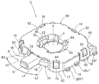
図1〜図4に示すように、この複合スイッチは、絶縁性材料で成る樹脂製のスイッチ本体10と、良導体で成る下側スイッチプレート30(接点板の一例)と、良導体で成る上側スイッチプレート40と、柔軟に変形する保護シート50と、良導体によりリング状に形成されるブラシユニット60と、レバー72が一体形成されたロータ70と、金属板材や樹脂製板材で成るカバー80とを備えている。尚、スイッチ本体10とカバー80とで複合スイッチのケースCが構成されている。
As shown in FIGS. 1 to 4, this composite switch includes a
本発明の複合スイッチは図1に示す姿勢で使用されるものとは限らないが、同図に示される如くスイッチ本体10を下側とし、カバー80を上側として説明する。
The composite switch of the present invention is not necessarily used in the posture shown in FIG. 1, but will be described with the
〔スイッチ本体〕
スイッチ本体10は、複数の固定接点20を有した底壁部11と、底壁部11の外周部位において上方に突出する外壁部12と、前述したブラシユニット60を下側から支持する一対のリブ状部13と、前述した保護シート50に係合する一対の保持突起14とが一体的に形成されている。外壁部12は、底壁部11から上方に突出形成する壁状に形成されるものであり、この外壁部12のうち平面視において前述したレバー72が配置される開放部Wが形成されている。
[Switch body]
The
また、外壁部12のうち、開放部Wに隣接する部位と、軸芯Xを挟んで開放部Wに対向する部位とに直線状の側壁15が形成されている。更に、開放部Wには軸芯Xを中心とする円弧状のガイド壁16が形成され、このガイド壁16の端部位置には、平面視で側壁15に対して傾斜する姿勢の傾斜壁17が形成されている。これにより外壁部12の外面形状は、3つの側壁15と、一対の傾斜壁17とにより一辺を切り欠いた正方形に近似する形状を成す。そして、3つの側壁15と、一対の傾斜壁17との外面には係合突起18が一体的に形成されている。
Moreover, the
前述したように外壁部12は、底壁部11から上方に突出形成する壁状に形成されており、前記開放部Wに対応する領域を除く領域において軸芯Xを中心とする円形の内周面12Sを有している。リブ状部13は、底壁部11から帯状に上方に突出する一対の成形物であり、軸芯Xを中心とする円弧状に形成されている。
As described above, the
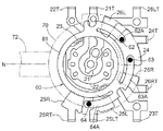
図5に示すように、底壁部11に形成される固定接点20として、軸芯X上に配置される中央接点21と、この外周に配置される下側用接点22と、この下側用接点22より更に外周側に配置される上側用接点23とをプッシュスイッチ部Pの構成物として備えている。また、固定接点20として、軸芯Xを中心とする仮想円周上に配置される主接点24と、この仮想円周上において主接点24から離間する位置において周方向に隣接配置される左第1接点25Lと、右第1接点25Rと、この仮想円周上において主接点24を挟む位置に配置される左第2接点26Lと、右第2接点26Rとをロータリスイッチ部Rの構成物として備えている。
As shown in FIG. 5, as the fixed
尚、固定接点20は、中央接点21(被接触接点の一例)と、下側用接点22と、上側用接点23と、主接点24と、左第1接点25Lと、右第1接点25Rと、一対の左第2接点26Lと、右第2接点26Rとの上位概念である。
The fixed
これら中央接点21と、下側用接点22と、上側用接点23と、主接点24と、左第1接点25Lと、右第1接点25Rと、左第2接点26Lと、右第2接点26Rとは銅合金等の良導体で成る金属板や金属箔等を底壁部11の上面に固着する形態で形成される。これらに対してプリント配線等の技術により電気的に接続するリード端子21T、22T、23T、24T、25LT、25RT、26LT、26RTが、3つの側壁15から外方に突出する形状に形成されている。尚、リード端子の符号として電気的に接続する各固定接点の番号に関連する符号を付している。
The
図5に示すように、主接点24と、左第1接点25Lと、右第1接点25Rと、左第2接点26Lと、右第2接点26Rとは、軸芯Xを基準にして開放部Wの領域に拡がる扇状領域を避けた位置に配置されている。
As shown in FIG. 5, the
〔スイッチプレート〕
下側スイッチプレート30は、弾性変形が可能な銅板等の円盤状の良導体を用いて中央が上方に突出するドーム状の下側プレート本体31と、その外周から外方に突出する一対の下側突出部32とを有する形状に成形されている。また、上側スイッチプレート40も下側スイッチプレート30と同様に、弾性変形が可能な銅板等の円盤状の良導体を用いて中央が上方に突出するドーム状の上側プレート本体41と、その外周から外方に突出する4つの上側突出部42とを有する形状に成形されている。
[Switch plate]
The
後述するように下側スイッチプレート30と上側スイッチプレート40とは、設定間隔を隔てた位置関係で上下に配置されるものであり、押圧力が作用した場合には上側スイッチプレート40が弾性変形により下側スイッチプレート30の上面に接触し、この接触状態を電気的に検出できるように構成されている。更に押圧力が作用した場合には下側スイッチプレート30が弾性変形することにより、この下側スイッチプレート30が中央接点21に接触し、この接触状態を電気的に検出できるように構成されている。
As will be described later, the
このような操作により2段階の押圧操作の検出を可能にするものであるが、1段目の操作と2段目の操作とを指の感覚で確認できるように、1段目と2段目との夫々の操作の初期には操作反力の感触を得ると共に、操作の終了近くでは操作反力が大きく低下する感触を得るように変形の特性を設定してクリック感を得ている。このような理由から、下側スイッチプレート30と上側スイッチプレート40との少なくとも一方を鋼材のように良好に弾性変形する材料を用いて形成しても良い。また、鋼材を用いる場合には両面に金鍍金を施すことにより良好な導電性を維持しても良い。
Such an operation enables detection of a two-stage pressing operation, but the first and second stages so that the first stage operation and the second stage operation can be confirmed with the sense of a finger. At the beginning of each operation, a feeling of the reaction force is obtained, and a deformation characteristic is set so as to obtain a feeling that the operation reaction force is greatly reduced near the end of the operation, thereby obtaining a click feeling. For this reason, at least one of the
〔保護シート〕
保護シート50は、電気的に絶縁性を有し、摩擦係数が低い円滑な表面を有した樹脂製で柔軟に変形し得るシート材を円形のシート本体51と、湾曲するように上方に突出する中央部の膨出部52と、外周の2箇所に切り込み部53とを形成した形状に構成されている。尚、2箇所の切り込み部53に対して前述した保持突起14が係入することにより、この保護シート50の回転が阻止されると同時に位置が決まる。
[Protective sheet]
The
〔ブラシユニット〕
ブラシユニット60は、図5に示すように、銅合金等の良導体で成る金属板を用いてリング状部61(回転導体の一例)と、これに一体形成された左主アーム部62Aの先端において下方に突出形成された左主接触子62と、右主アーム部63Aの先端において下方に突出形成された右主接触子63と、リング状部61に一体形成された1つの副アーム部64Aの先端において下方に突出形成された副接触子64と、一対の係合凹部65とを形成した構造を有している。このブラシユニット60では、左主アーム部62Aと右主アーム部63Aと副アーム部64Aの外周縁との外周径を、スイッチ本体10の外壁部12の内周面12Sの内径より僅かに小さく設定することで、軸芯Xを中心として回転自在にスイッチ本体10に支持される。
[Brush unit]
As shown in FIG. 5, the
このブラシユニット60は、リング状部61の下面側を前述した一対のリブ状部13の上面の部位において保護シート50に載置される位置に支持される。また、2つの左主アーム部62Aと、右主アーム部63Aと、副アーム部64Aをリング状部61から下方に張り出す傾斜姿勢に成形することで左主接触子62、右主接触子63、副接触子64夫々を下方に突出させている。
The
左主接触子62と、右主接触子63とは周方向で隣接する位置に配置され、これらから離間する位置に1つの副接触子64が配置され、これらは軸芯Xを中心とする仮想円周上に配置されている。
The left
〔ロータ〕
ロータ70は、絶縁性の樹脂材料等によりリング状のロータ本体71と、レバー72とを一体形成すると共に、下面側にはブラシユニット60の係合凹部65に係入する突起部(図示せず)を形成した構造を有している。このロータ本体71の外周径をスイッチ本体10の外壁部12の内周面12Sの内径より僅かに小さく設定することで、ロータ70は軸芯Xを中心として回転自在にスイッチ本体10に支持される。
[Rotor]
The
ロータ本体71の外周面のうちレバー72が形成された部位の近傍に小径領域71Aの外周径を小径化しており、この小径領域71Aにおいて一対の傾斜壁17に制限されることなくロータ70の回転が許容される。
The outer diameter of the small-
〔カバー〕
カバー80は、平面視でスイッチ本体10と略一致する形状のカバー本体81を有すると共に、外周の5箇所に突出片82が形成され、これらに係合孔部83が穿設されている。また、カバー本体81の中央部には開口84が形成され、この開口84から下方に突出する押圧片85が形成されている。
〔cover〕
The
このような構成から、中央接点21と、下側用接点22と、上側用接点23と、下側スイッチプレート30と、上側スイッチプレート40とでプッシュスイッチ部Pが構成されている。更に、主接点24と、一対の第1接点25R、25Lと、一対の第2接点26R、26Lと、ブラシユニット60の2つの左主接触子62、右主接触子63及び1つの副接触子64と、レバー72で操作されるロータ70とによってロータリスイッチ部Rが構成されている。
With such a configuration, the
〔複合スイッチの構造〕
スイッチ本体10に対して、下側スイッチプレート30、上側スイッチプレート40、保護シート50、ブラシユニット60、ロータ70、カバー80夫々を重ね合わせ、スイッチ本体10に対して軸芯Xに沿う方向にカバー80を押圧することで、カバー80の複数の突出片82を外側に弾性変形させ、この突出片82の係合孔部83に対してスイッチ本体10の複数の係合突起18が係合した状態で、突出片82の弾性的な復元力により係合孔部83に対する係合突起18の係合状態が維持され、複合スイッチの組み立てが完了する。
[Composite switch structure]
The
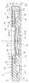
この組み立て状態では、図3、図4に示すように、下側プレート本体31の下側突出部32が底壁部11に係合すると同時に、この下側プレート本体31の外周部が下側用接点22に接触して電気的な導通状態に達する。また、上側プレート本体41の上側突出部42(図2を参照)が底壁部11に係合すると同時に、この上側突出部42が上側用接点23に接触して電気的な導通状態に達する。また、下側プレート本体31と上側プレート本体41とは上下方向で設定距離だけ離間した位置関係で配置されることになり、保護シート50のシート本体51の膨出部52が上側プレート本体41の上面を覆い、このシート本体51の外周部分が一対のリブ状部13の上面に接触する状態となる。
In this assembled state, as shown in FIGS. 3 and 4, the
このシート本体51の切り込み部53が保持突起14に係合することで、保護シート50の位置が決まると同時に回転が抑制される。このシート本体51の外周部分の上面にブラシユニット60のリング状部61が支持され、このブラシユニット60の2つの左主接触子62、右主接触子63及び1つの副接触子64は、主接点24と、左第1接点25Lと、右第1接点25Rと、左第2接点26Lと、右第2接点26Rとのうち対応するものに接触する(この接触の形態は後述する)。
By engaging the
ブラシユニット60の上面にロータ70のロータ本体71が接触し、このロータ本体71の突起部(図示せず)がブラシユニット60の係合凹部65に係合することで、レバー72の回転操作時にはブラシユニット60が一体的に回動する。そして、この組み立て状態では、前述したようにプッシュスイッチ部Pにおいて押圧操作の2段階の検出が可能となり、また、ロータリスイッチ部Rにおいて、中立姿勢Nを基準にするレバー72の左回転と右回転とにおける2段階の検出が可能となる。
The rotor
カバー80の下面にロータ本体71が接触することで、このロータ本体71とブラシユニット60との分離が抑制され、また、カバー80の開口84の押圧片85がシート本体51の浮き上がりを抑制する。
When the rotor
〔検出形態〕
このような複合スイッチにおいて、カバー80の開口84を介して押圧操作力が作用した場合には、保護シート50の膨出部52が柔軟に変形することにより、上側スイッチプレート40の上側プレート本体41の中央部が下方に向けて窪むように弾性変形が行われる。この弾性変形により、その中央部の下面が下側スイッチプレート30の下側プレート本体31の中央部に接触し、上側用接点23と下側用接点22とが電気的な導通状態に達し、この1段目までの操作の検出が可能となる。
[Detection type]
In such a composite switch, when a pressing operation force is applied through the
この押し操作を継続することにより、上側プレート本体41の中央部から下側プレート本体31の中央部に押圧操作力が作用して、下側プレート本体31の中央部が下方に向けて窪むように弾性変形が行われる。この弾性変形により、その中央部の下面が中央接点21に接触し、下側用接点22と中央接点21とが電気的な導通状態に達し、この2段目までの操作の検出が可能となる。
By continuing this pushing operation, a pressing operation force acts on the center portion of the
この複合スイッチでは、中立姿勢Nを基準にしてレバー72を右方向(一方)に向け第1右操作位置R1と第2右操作位置R2とに操作でき、これと同様に、レバー72を左方向(他方)に向け第1左操作位置L1と第2左操作位置L2とに操作できるように構成されている。
With this composite switch, the
レバー72が中立姿勢Nにある状態では、図6に示すように、左主接触子62と右主接触子63とが主接点24に接触して電気的な導通状態にあるが、副接触子64は左第1接点25Lと右第1接点25Rとの中間位置で、何れにも接触しない状態となる。
In the state where the
この中立姿勢Nを基準にしてレバー72が第1左操作位置L1まで回転操作された際には、図7に示すように、少なくとも右主接触子63が主接点24に接触する状態を維持しながら、副接触子64が左第1接点25Lに接触することで、この左第1接点25Lを主接点24と同電位にする。更に、レバー72が第2左操作位置L2まで回転操作された際には、図8に示すように、右主接触子63が主接点24に接触する状態を維持しながら、副接触子64が左第2接点26Lに接触することで、この左第2接点26Lを主接点24と同電位にする。
When the
これとは逆に、中立姿勢Nを基準にしてレバー72が第1右操作位置R1まで回転操作された際には、図9に示すように、少なくとも左主接触子62が主接点24に接触する状態を維持しながら、副接触子64が右第1接点25Rに接触することで、この右第1接点25Rを主接点24と同電位にする。更に、レバー72が第2右操作位置R2まで回転操作された際には、図10に示すように、左主接触子62が主接点24に接触する状態を維持しながら、副接触子64が右第2接点26Rに接触することで、この右第2接点26Rを主接点24と同電位にする。
On the contrary, when the
つまり、ブラシユニット60が中立姿勢Nから正方向(例えば、左側)に回転した際には、一対の主接触子62、63の一方(右主接触子63)が主接点24に接触する状態で、副接触子64が一対の第1接点25L、25Rのうち正回転方向側のもの(左第1接点25L)に接触する。更に回転した際には、一対の主接触子62、63の一方(右主接触子63)が主接点24に接触する状態で一対の主接触子62、63の他方(左主接触子62)が一対の第2接点26L、26Rのうち正回転方向側のもの(左第2接点26L)に接触する。
That is, when the
これとは逆に、ブラシユニット60が中立姿勢Nから逆方向(例えば、右側)に回転した際には、一対の主接触子62、63の他方(左主接触子62)が主接点24に接触する状態で副接触子64が一対の第1接点25L、25Rのうち逆回転方向側のもの(右第1接点25R)に接触し、更に回転した際には、一対の主接触子62、63の他方(左主接触子62)が主接点24に接触する状態で一対の主接触子62、63の一方(右主接触子63)が一対の第2接点26L、26Rのうち逆回転方向側のもの(右第2接点26R)に接触するのである。
On the contrary, when the
この複合スイッチでは、主接点24をグランドレベルの電位に設定することで、固定接点20の電位がグランドレベルまで低下することからスイッチの操作を検出する形態で使用することを想定しているが、この主接点に24に任意の電圧を印加して使用しても良い。この場合、固定接点20の電圧が上昇することからスイッチの操作が検出されることになる。
In this composite switch, it is assumed that the operation of the switch is detected because the potential of the fixed
このように、本発明の複合スイッチでは、プッシュスイッチ部Pにおいて押圧操作が行われた場合には、押圧操作のストロークに対応してクリック感を伴う2段階の検出が可能となる。また、ロータリスイッチ部Rにおいて回転操作が行われた場合には、中立姿勢Nを基準として一方と他方とにおいて回転操作のストロークに対応して2段階の検出が可能となる。 As described above, in the composite switch of the present invention, when a pressing operation is performed in the push switch portion P, two-step detection with a click feeling corresponding to the stroke of the pressing operation is possible. Further, when a rotary operation is performed in the rotary switch portion R, two steps of detection can be performed in accordance with the stroke of the rotary operation in one and the other with respect to the neutral posture N.
特に、ロータリスイッチ部Rでは、中立姿勢Nを基準にして、一方(例えば左側)への回転操作を2段階で検出し、他方(例えば右側)への回転操作を2段階で検出することで、中立姿勢Nを除いても4姿勢への回転操作検出するものでありながら、ブラシユニット60の外周に形成される接触子を3つで済むものにしている。このようにブラシユニット60の外周に形成される接触子を3つにすることで、例えば、4姿勢に対応して接触子を4つ備えるものと比較すると、ブラシユニット60の小型化を実現すると同時に、接触子に接触する接点が配置されるエリアを小さくして、複合スイッチの小型化を実現しているのである。
In particular, in the rotary switch unit R, the rotation operation to one (for example, the left side) is detected in two stages with the neutral posture N as a reference, and the rotation operation to the other (for example, the right side) is detected in two stages. Even if the neutral posture N is removed, the rotation operation to the four postures is detected, but only three contacts are formed on the outer periphery of the
本発明は、デジタルカメラ以外にオーディオ機器や携帯電話機に利用することができる。 The present invention can be used for audio devices and mobile phones in addition to digital cameras.
10 スイッチ本体
11 底壁部
15 側壁
21 被接触接点(中央接点)
24 主接点
24T リード端子
25L 第1接点(左第1接点)
25LT リード端子
25R 第1接点(右第1接点)
25RT リード端子
26L 第2接点(左第2接点)
26LT リード端子
26R 第2接点(右第2接点)
26RT リード端子
30 接点板(下側スイッチプレート)
60 ブラシユニット
61 回転導体(リング状部)
62 主接触子(左主接触子)
62 主接触子(右主接触子)
63 副接触子
72 レバー
N 中立姿勢
P プッシュスイッチ部
R ロータリスイッチ部
W 開放部
X 軸芯
10
24
60
62 Main contact (Left main contact)
62 Main contact (right main contact)
63
Claims (3)
前記ブラシユニットの接触子として、隣接配置される一対の主接触子と、単一の副接触子とを前記軸芯を中心とする同一円周上に備え、
前記固定接点として、前記ブラシユニットが中立姿勢にある際に一対の前記主接触子が同時に接触する主接点と、この中立姿勢において前記副接触子を周方向から挟む位置に離間して配置される一対の第1接点と、この中立姿勢において前記主接点を周方向から挟む位置に離間して配置される一対の第2接点とを備え、
前記ブラシユニットが前記中立姿勢から正方向に回転した際には、一対の前記主接触子の一方が前記主接点に接触する状態で前記副接触子が一対の前記第1接点のうち正回転方向側のものに接触し、更に回転した際には、一対の前記主接触子の一方が前記主接点に接触する状態で一対の前記主接触子の他方が一対の前記第2接点のうち正回転方向側のものに接触し、
前記ブラシユニットが前記中立姿勢から逆方向に回転した際には、一対の前記主接触子の他方が前記主接点に接触する状態で前記副接触子が一対の前記第1接点のうち逆回転方向側のものに接触し、更に回転した際には、一対の前記主接触子の他方が前記主接点に接触する状態で一対の前記主接触子の一方が一対の前記第2接点のうち逆回転方向側のものに接触するように、接触子と固定接点とが配置され、
前記レバーが配置される開放部が、スイッチ本体に前記軸芯を中心とする扇状に形成され、前記主接点と、前記第1接点と、前記第2接点とが、前記開放部の扇状の領域を避けた位置に配置されると共に、前記ブラシユニットの前記主接触子と、前記副接触子とが前記開放部の扇状の領域を避けた位置に配置されている複合スイッチ。 A push switch unit that detects a pressing operation and a rotary switch unit that detects a rotation operation. The push switch unit is elastically deformed by the pressing operation, and the contact plate is brought into contact with the contact plate by elastic deformation of the contact plate. And a contact unit that reaches a conductive state, and the rotary switch unit includes a brush unit in which a plurality of contacts are formed on a rotating conductor that rotates around an axis by operation of a lever; A composite switch configured to include a plurality of fixed contacts that can conduct to the contact,
As a contact of the brush unit, a pair of adjacent main contacts and a single sub-contact are provided on the same circumference centered on the axis,
As the fixed contact, when the brush unit is in a neutral posture, a pair of the main contacts are simultaneously contacted, and in this neutral posture, they are spaced apart from each other so as to sandwich the sub contact from the circumferential direction. A pair of first contacts, and a pair of second contacts that are spaced apart at a position sandwiching the main contact from the circumferential direction in this neutral posture,
When the brush unit is rotated in the forward direction from the neutral posture, the sub-contact is in the positive rotation direction of the pair of first contacts while one of the pair of main contacts is in contact with the main contact. When one of the pair of main contacts contacts the main contact, the other of the pair of main contacts rotates forward of the pair of second contacts. Touch the directional side,
When the brush unit is rotated in the reverse direction from the neutral posture, the sub-contact is in the reverse rotation direction of the pair of first contacts while the other of the pair of main contacts is in contact with the main contact. One of the pair of main contacts is reversely rotated out of the pair of second contacts while the other of the pair of main contacts is in contact with the main contact. The contact and the fixed contact are arranged so as to contact the direction side ,
The open portion in which the lever is disposed is formed in a fan shape centered on the shaft core in the switch body, and the main contact, the first contact, and the second contact are fan-shaped regions of the open portion. A composite switch in which the main contact and the sub-contact of the brush unit are disposed at a position avoiding a fan-shaped area of the open portion .
Priority Applications (8)
| Application Number | Priority Date | Filing Date | Title |
|---|---|---|---|
| JP2009133299A JP4886816B2 (en) | 2009-06-02 | 2009-06-02 | Compound switch |
| KR1020100035352A KR101204171B1 (en) | 2009-06-02 | 2010-04-16 | Composite switch |
| TW099112508A TWI390566B (en) | 2009-06-02 | 2010-04-21 | Compound switch |
| AT10005264T ATE543193T1 (en) | 2009-06-02 | 2010-05-20 | COMBINATION SWITCH |
| EP10005264A EP2259280B1 (en) | 2009-06-02 | 2010-05-20 | Combination switch |
| US12/784,833 US8217282B2 (en) | 2009-06-02 | 2010-05-21 | Combination switch |
| CA2705958A CA2705958C (en) | 2009-06-02 | 2010-05-31 | Combination switch |
| CN201010200329.4A CN101908431B (en) | 2009-06-02 | 2010-06-01 | Combination switch |
Applications Claiming Priority (1)
| Application Number | Priority Date | Filing Date | Title |
|---|---|---|---|
| JP2009133299A JP4886816B2 (en) | 2009-06-02 | 2009-06-02 | Compound switch |
Publications (2)
| Publication Number | Publication Date |
|---|---|
| JP2010282756A JP2010282756A (en) | 2010-12-16 |
| JP4886816B2 true JP4886816B2 (en) | 2012-02-29 |
Family
ID=42674620
Family Applications (1)
| Application Number | Title | Priority Date | Filing Date |
|---|---|---|---|
| JP2009133299A Active JP4886816B2 (en) | 2009-06-02 | 2009-06-02 | Compound switch |
Country Status (8)
| Country | Link |
|---|---|
| US (1) | US8217282B2 (en) |
| EP (1) | EP2259280B1 (en) |
| JP (1) | JP4886816B2 (en) |
| KR (1) | KR101204171B1 (en) |
| CN (1) | CN101908431B (en) |
| AT (1) | ATE543193T1 (en) |
| CA (1) | CA2705958C (en) |
| TW (1) | TWI390566B (en) |
Families Citing this family (4)
| Publication number | Priority date | Publication date | Assignee | Title |
|---|---|---|---|---|
| JP4531793B2 (en) * | 2007-06-11 | 2010-08-25 | ホシデン株式会社 | Combined operation type input device |
| DE202015009305U1 (en) * | 2015-08-10 | 2017-01-30 | Ellenberger & Poensgen Gmbh | switching system |
| JP7340490B2 (en) * | 2020-04-15 | 2023-09-07 | ホシデン株式会社 | Seat belt attachment/detaching detection switch |
| WO2022263914A1 (en) * | 2021-06-16 | 2022-12-22 | Nikhil Kachattiyawar | System for hybrid switch assembly and rotary switch assembly for controlling appliances |
Family Cites Families (16)
| Publication number | Priority date | Publication date | Assignee | Title |
|---|---|---|---|---|
| FR2759199B1 (en) * | 1997-01-31 | 1999-03-26 | Itt Composants Instr | MODULAR ELECTRICAL SWITCHING DEVICE |
| JP2001135197A (en) * | 1999-11-02 | 2001-05-18 | Matsushita Electric Ind Co Ltd | Depression/rotation-operated electronic part |
| US6236002B1 (en) * | 2000-05-03 | 2001-05-22 | Shin Jiuh Corp. | Multiple switch assembly including cam operated rotary switch contacts and axially located pushbutton switch |
| JP2001357758A (en) * | 2000-06-12 | 2001-12-26 | Alps Electric Co Ltd | Combined control input device |
| JP4620894B2 (en) * | 2001-04-06 | 2011-01-26 | キヤノン株式会社 | Electronics |
| JP3864812B2 (en) * | 2002-03-07 | 2007-01-10 | 松下電器産業株式会社 | Composite operation type electronic parts |
| US6680444B1 (en) * | 2002-10-30 | 2004-01-20 | Shin-Jiuh Corp. | Structure of a switch for electronic device |
| JP2005108570A (en) * | 2003-09-29 | 2005-04-21 | Mitsumi Electric Co Ltd | Combined control switching device |
| CN2650318Y (en) * | 2003-11-03 | 2004-10-20 | 郭万国 | Selective button composite switch structure |
| TWM291597U (en) * | 2005-04-01 | 2006-06-01 | Hon Hai Prec Ind Co Ltd | A pushbutton and rotary switch |
| JP4635774B2 (en) * | 2005-08-03 | 2011-02-23 | パナソニック株式会社 | Combined operation type switch |
| JP4306669B2 (en) * | 2005-10-11 | 2009-08-05 | オムロン株式会社 | Operation input device and electronic apparatus using the same |
| JP4353964B2 (en) * | 2006-06-26 | 2009-10-28 | ホシデン株式会社 | Combined operation type input device |
| JP5157158B2 (en) * | 2006-12-25 | 2013-03-06 | カシオ計算機株式会社 | Contact device |
| JP4315983B2 (en) * | 2007-01-19 | 2009-08-19 | ホシデン株式会社 | Compound switch |
| JP4521450B2 (en) * | 2008-03-14 | 2010-08-11 | ホシデン株式会社 | Combined operation type input device |
-
2009
- 2009-06-02 JP JP2009133299A patent/JP4886816B2/en active Active
-
2010
- 2010-04-16 KR KR1020100035352A patent/KR101204171B1/en active IP Right Grant
- 2010-04-21 TW TW099112508A patent/TWI390566B/en active
- 2010-05-20 EP EP10005264A patent/EP2259280B1/en active Active
- 2010-05-20 AT AT10005264T patent/ATE543193T1/en active
- 2010-05-21 US US12/784,833 patent/US8217282B2/en active Active
- 2010-05-31 CA CA2705958A patent/CA2705958C/en active Active
- 2010-06-01 CN CN201010200329.4A patent/CN101908431B/en active Active
Also Published As
| Publication number | Publication date |
|---|---|
| JP2010282756A (en) | 2010-12-16 |
| TW201110177A (en) | 2011-03-16 |
| EP2259280A2 (en) | 2010-12-08 |
| KR101204171B1 (en) | 2012-11-22 |
| TWI390566B (en) | 2013-03-21 |
| US8217282B2 (en) | 2012-07-10 |
| CA2705958C (en) | 2016-08-02 |
| EP2259280A3 (en) | 2011-03-30 |
| US20100300851A1 (en) | 2010-12-02 |
| EP2259280B1 (en) | 2012-01-25 |
| CN101908431B (en) | 2014-08-20 |
| CA2705958A1 (en) | 2010-12-02 |
| CN101908431A (en) | 2010-12-08 |
| ATE543193T1 (en) | 2012-02-15 |
| KR20100130143A (en) | 2010-12-10 |
Similar Documents
| Publication | Publication Date | Title |
|---|---|---|
| EP2755220B1 (en) | Switch | |
| EP1947668B1 (en) | Combined switch | |
| EP1026713B1 (en) | Pressing and rotating operation type electronic parts and communication terminal equipment using the electronic parts | |
| KR100356195B1 (en) | Electronic parts of press turn-operating type | |
| JP4511479B2 (en) | Combined operation switch | |
| US7652217B2 (en) | Rotary type pulse switch | |
| JP4886816B2 (en) | Compound switch | |
| JP3763044B2 (en) | Multi-directional switch | |
| JP2003249151A (en) | Multi-direction operation switch | |
| JP4439478B2 (en) | Combined operation switch | |
| JP2003234047A (en) | Multi-direction operation switch | |
| JP2005302348A (en) | Multidirectional operation switch | |
| JP5257013B2 (en) | Combined operation type switch | |
| JP4097213B2 (en) | Multi-directional input device | |
| JP4577517B2 (en) | Input device | |
| JP2007311097A (en) | Operating body for compound operation | |
| JPH058841U (en) | Date switch | |
| JP2007227005A (en) | Compound operation switch |
Legal Events
| Date | Code | Title | Description |
|---|---|---|---|
| A621 | Written request for application examination |
Free format text: JAPANESE INTERMEDIATE CODE: A621 Effective date: 20110427 |
|
| A977 | Report on retrieval |
Free format text: JAPANESE INTERMEDIATE CODE: A971007 Effective date: 20110824 |
|
| A131 | Notification of reasons for refusal |
Free format text: JAPANESE INTERMEDIATE CODE: A131 Effective date: 20110901 |
|
| A521 | Request for written amendment filed |
Free format text: JAPANESE INTERMEDIATE CODE: A523 Effective date: 20111028 |
|
| TRDD | Decision of grant or rejection written | ||
| A01 | Written decision to grant a patent or to grant a registration (utility model) |
Free format text: JAPANESE INTERMEDIATE CODE: A01 Effective date: 20111124 |
|
| A01 | Written decision to grant a patent or to grant a registration (utility model) |
Free format text: JAPANESE INTERMEDIATE CODE: A01 |
|
| A61 | First payment of annual fees (during grant procedure) |
Free format text: JAPANESE INTERMEDIATE CODE: A61 Effective date: 20111209 |
|
| FPAY | Renewal fee payment (event date is renewal date of database) |
Free format text: PAYMENT UNTIL: 20141216 Year of fee payment: 3 |
|
| R150 | Certificate of patent or registration of utility model |
Ref document number: 4886816 Country of ref document: JP Free format text: JAPANESE INTERMEDIATE CODE: R150 Free format text: JAPANESE INTERMEDIATE CODE: R150 |