JP4886683B2 - Internally connected dental implant - Google Patents
Internally connected dental implant Download PDFInfo
- Publication number
- JP4886683B2 JP4886683B2 JP2007519300A JP2007519300A JP4886683B2 JP 4886683 B2 JP4886683 B2 JP 4886683B2 JP 2007519300 A JP2007519300 A JP 2007519300A JP 2007519300 A JP2007519300 A JP 2007519300A JP 4886683 B2 JP4886683 B2 JP 4886683B2
- Authority
- JP
- Japan
- Prior art keywords
- dental implant
- distal end
- diameter
- abutment
- lobes
- Prior art date
- Legal status (The legal status is an assumption and is not a legal conclusion. Google has not performed a legal analysis and makes no representation as to the accuracy of the status listed.)
- Active
Links
- 239000004053 dental implant Substances 0.000 title claims abstract description 71
- 239000007943 implant Substances 0.000 claims abstract description 95
- 206010044565 Tremor Diseases 0.000 claims 1
- 230000005540 biological transmission Effects 0.000 description 5
- 238000009434 installation Methods 0.000 description 5
- 230000006641 stabilisation Effects 0.000 description 5
- 238000011105 stabilization Methods 0.000 description 5
- 230000000295 complement effect Effects 0.000 description 4
- 230000000087 stabilizing effect Effects 0.000 description 3
- 230000000712 assembly Effects 0.000 description 2
- 238000000429 assembly Methods 0.000 description 2
- 230000007704 transition Effects 0.000 description 2
- 208000037408 Device failure Diseases 0.000 description 1
- 230000008859 change Effects 0.000 description 1
- 238000010276 construction Methods 0.000 description 1
- 230000007547 defect Effects 0.000 description 1
- 238000004519 manufacturing process Methods 0.000 description 1
- 230000004048 modification Effects 0.000 description 1
- 238000012986 modification Methods 0.000 description 1
- 230000009467 reduction Effects 0.000 description 1
Images


Classifications
-
- A—HUMAN NECESSITIES
- A61—MEDICAL OR VETERINARY SCIENCE; HYGIENE
- A61C—DENTISTRY; APPARATUS OR METHODS FOR ORAL OR DENTAL HYGIENE
- A61C8/00—Means to be fixed to the jaw-bone for consolidating natural teeth or for fixing dental prostheses thereon; Dental implants; Implanting tools
-
- A—HUMAN NECESSITIES
- A61—MEDICAL OR VETERINARY SCIENCE; HYGIENE
- A61C—DENTISTRY; APPARATUS OR METHODS FOR ORAL OR DENTAL HYGIENE
- A61C8/00—Means to be fixed to the jaw-bone for consolidating natural teeth or for fixing dental prostheses thereon; Dental implants; Implanting tools
- A61C8/0048—Connecting the upper structure to the implant, e.g. bridging bars
- A61C8/005—Connecting devices for joining an upper structure with an implant member, e.g. spacers
- A61C8/0066—Connecting devices for joining an upper structure with an implant member, e.g. spacers with positioning means
-
- A—HUMAN NECESSITIES
- A61—MEDICAL OR VETERINARY SCIENCE; HYGIENE
- A61C—DENTISTRY; APPARATUS OR METHODS FOR ORAL OR DENTAL HYGIENE
- A61C8/00—Means to be fixed to the jaw-bone for consolidating natural teeth or for fixing dental prostheses thereon; Dental implants; Implanting tools
- A61C8/0048—Connecting the upper structure to the implant, e.g. bridging bars
- A61C8/005—Connecting devices for joining an upper structure with an implant member, e.g. spacers
- A61C8/0069—Connecting devices for joining an upper structure with an implant member, e.g. spacers tapered or conical connection
-
- A—HUMAN NECESSITIES
- A61—MEDICAL OR VETERINARY SCIENCE; HYGIENE
- A61C—DENTISTRY; APPARATUS OR METHODS FOR ORAL OR DENTAL HYGIENE
- A61C8/00—Means to be fixed to the jaw-bone for consolidating natural teeth or for fixing dental prostheses thereon; Dental implants; Implanting tools
- A61C8/0048—Connecting the upper structure to the implant, e.g. bridging bars
- A61C8/005—Connecting devices for joining an upper structure with an implant member, e.g. spacers
- A61C8/0054—Connecting devices for joining an upper structure with an implant member, e.g. spacers having a cylindrical implant connecting part
-
- A—HUMAN NECESSITIES
- A61—MEDICAL OR VETERINARY SCIENCE; HYGIENE
- A61C—DENTISTRY; APPARATUS OR METHODS FOR ORAL OR DENTAL HYGIENE
- A61C8/00—Means to be fixed to the jaw-bone for consolidating natural teeth or for fixing dental prostheses thereon; Dental implants; Implanting tools
- A61C8/0048—Connecting the upper structure to the implant, e.g. bridging bars
- A61C8/005—Connecting devices for joining an upper structure with an implant member, e.g. spacers
- A61C8/0068—Connecting devices for joining an upper structure with an implant member, e.g. spacers with an additional screw
-
- A—HUMAN NECESSITIES
- A61—MEDICAL OR VETERINARY SCIENCE; HYGIENE
- A61C—DENTISTRY; APPARATUS OR METHODS FOR ORAL OR DENTAL HYGIENE
- A61C8/00—Means to be fixed to the jaw-bone for consolidating natural teeth or for fixing dental prostheses thereon; Dental implants; Implanting tools
- A61C8/0048—Connecting the upper structure to the implant, e.g. bridging bars
- A61C8/005—Connecting devices for joining an upper structure with an implant member, e.g. spacers
- A61C8/0069—Connecting devices for joining an upper structure with an implant member, e.g. spacers tapered or conical connection
- A61C8/0071—Connecting devices for joining an upper structure with an implant member, e.g. spacers tapered or conical connection with a self-locking taper, e.g. morse taper
Abstract
Description
1.発明の分野
本発明は一般に歯科インプラントの分野、より具体的には、内部接続型インプラントに関する。本発明はまた、内部接続型インプラント及びこれと相補的なアバットメントの組合せに関する。
2.従来技術の説明
この技術分野には現在多種多様の歯科インプラントが存在する。そのような歯科インプラントは通常、患者の口腔内にインプラントを取り付け保持する雄ねじを備えた本体を含む。インプラントの装着には、ラチェット又は他の回転手段等の駆動部材を使用して、事前に穴を開けた又はねじ立てした場所にインプラントを回転して入れることが必要である。インプラントはまた、外部又は内部に位置する駆動領域を含む。インプラントを外部及び内部駆動する様々な構造体が現在存在する。
1. The present invention relates generally to the field of dental implants, and more specifically to interconnected implants. The invention also relates to an interconnected implant and a complementary abutment combination.
2. 2. Description of the Prior Art A wide variety of dental implants currently exist in this technical field. Such dental implants typically include a body with external threads that attach and hold the implant in the patient's mouth. Installation of the implant requires rotation of the implant into a pre-drilled or tapped location using a drive member such as a ratchet or other rotating means. The implant also includes a drive region located externally or internally. Various structures currently exist that drive the implant externally and internally.
多くの内部駆動型の歯科インプラントは、インプラントとアバットメント間の十分なトルク伝達及び安定性を提供するが、インプラントの接続不具合は存在し続ける。それ故、改善されたトルク伝達及びインプラント/アバットメント安定性を提供すると共に、インプラントの接続不具合を最小にすることができる構造を備えた内部接続又は内部駆動型インプラントが引き続き必要である。 Many internally driven dental implants provide sufficient torque transmission and stability between the implant and the abutment, but implant failure continues to exist. Therefore, there is a continuing need for internally connected or internally driven implants with structures that provide improved torque transmission and implant / abutment stability while minimizing implant connection failures.
本発明は、歯科インプラントと、歯科インプラント及びアバットメントを組み合わせた組立体、より具体的には内部接続型歯科インプラントと、内部接続型インプラント及びアバットメントを組み合わせた組立体に関する。 The present invention relates to a dental implant, an assembly combining a dental implant and an abutment, and more particularly to an internally connected dental implant and an assembly combining an internally connected implant and an abutment.
一般に、本発明の歯科インプラントは駆動又は割出領域を含み、該領域は応力分布を一様にし、またインプラントの全接続部に亘ってトルク伝送能力を増大させ、これによりインプラントの接続不具合を最小にしかつすべてのサイズのインプラントに使用できる駆動手段を提供する。本発明によるインプラントはまた、インプラントとアバットメント間に高度に安定した接続を提供する安定化領域を含む。 In general, the dental implants of the present invention include a drive or index region that provides a uniform stress distribution and increases torque transmission across all implant connections, thereby minimizing implant connection failures. And provides a drive means that can be used for all sizes of implants. The implant according to the invention also includes a stabilization region that provides a highly stable connection between the implant and the abutment.
好ましい実施の形態において、駆動及び割出領域は、寸法が等しくかつ形状が等しい複数の凹状及び凸状ローブ(lobe)を含み、該ローブは小径円と大径円の間に位置決めされる。このローブ付形状(lobedconfiguration)は、装着時レンチ又は他の駆動手段と接触する表面積を増大させると共に、十分な厚みのインプラント外壁を提供し、特に軸外装填(off−axisloading)を収容する時にインプラントの接続不具合への抵抗を改善する。 In a preferred embodiment, the drive and index regions include a plurality of concave and convex lobes that are equal in size and shape, and the lobes are positioned between the small and large diameter circles . This lobed configuration increases the surface area in contact with the wrench or other drive means during installation and provides a sufficiently thick implant outer wall, especially when accommodating off-axis loading. Improve resistance to connection failures.
好ましい実施の形態において、インプラント及び対応するアバットメント間の相対運動、いわゆる微動を最小にし、したがってインプラントとアバットメント間の安定性を改善する安定化領域は、駆動及び割出区域と、インプラントの基端側端部との間に位置決めされた斜面を含む。この斜面はアバットメントの対応する斜面と結合する。この斜面の角度は、インプラントとアバットメント間の接点を安定化させるため摩擦嵌合を形成するのに十分なものである。 In a preferred embodiment, the stabilization region that minimizes the relative movement between the implant and the corresponding abutment, the so-called microtremor, and thus improves the stability between the implant and the abutment, comprises the drive and indexing areas, the implant base and A slope positioned between the end and the end. This slope is combined with the corresponding slope of the abutment. This bevel angle is sufficient to form a friction fit to stabilize the contact between the implant and the abutment.
それ故、本発明の目的は、回転又は駆動トルクの改善を容易にし、同時に装着及び使用時にインプラント接続の不具合を最小にする内部接続型歯科インプラント及び組立体を提供することにある。 Accordingly, it is an object of the present invention to provide an internally connected dental implant and assembly that facilitates improved rotation or drive torque while minimizing implant connection failures during installation and use.
本発明の別の目的は、インプラント及び対応するアバットメント間の安定性を提供する内部接続型歯科インプラント及び組立体を提供することにある。
本発明のこれらの及び他の目的は、図面、好ましい実施の形態の説明及び添付の特許請求の範囲を参照することによって明らかとなろう。
It is another object of the present invention to provide an internally connected dental implant and assembly that provides stability between the implant and the corresponding abutment.
These and other objects of the invention will become apparent upon reference to the drawings, the description of the preferred embodiments, and the appended claims.
本発明は、歯科インプラント及び歯科インプラント組立体、より具体的には、内部駆動又は内部接続型インプラント及び対応する歯科インプラント組立体を対象とする。
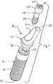
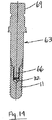
まず、分解した形(図1)と、組み立てた又は接続した形(図2)の歯科インプラント組立体10を示す図1及び2を参照する。歯科組立体10は、歯科インプラント11と、アバットメント12と、アバットメント又は接続ねじ14を含む。歯科インプラント11は、末端側端部15と、基端側端部16と、本体部13と、本体上の複数の雄ねじ18を含む。アバットメントは、末端側端部19と、基端側端部20と、内部接続用ボア又は開口17を含む。接続ねじ14は、末端側端部21と基端側端部23を含む。ねじ14にはその末端側端部21の近くに複数の雄ねじ24、基端側端部23の近くにはヘッド22が設けられる。ヘッド22には、内部六角、内部四角又は他の駆動面等のレンチ係合手段25が設けられる。
The present invention is directed to dental implants and dental implant assemblies, and more particularly to internal drive or internally connected implants and corresponding dental implant assemblies.
Reference is first made to FIGS. 1 and 2 showing a
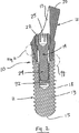
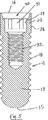
次に、歯科インプラント11の様々な図を示す図3、4、5及び6を参照する。インプラント11は、末端側端部15と、基端側端部16と、インプラント外面上の雄ねじ18の形をしたインプラント保持手段を含む。このねじ18は、患者の顎骨にインプラントを装着するのを容易にし、装着後インプラントを定着させ保持する。本実施の形態ではインプラント保持手段はインプラントの外面の大部分に及ぶ単一の連続ねじ18を備えるが、そのような保持手段としてはこの技術分野で現在知られ又は今後知られる任意の保持手段を含むことができ、多条ねじ、テーパねじ、異なった高さの交番ねじ(alternating threads)又はねじを備えない保持手段を含むが、これらに限定されるものではない。
Reference is now made to FIGS. 3, 4, 5 and 6 which show various views of the
インプラント11はさらに基端側端部16の近くに位置する外壁部26を含む。図4及び5に示すように、壁26はねじ付でない全体に筒状の外面28と内面29により規定される。面29は、以下に説明する内部ローブ付形状を規定し、またこれによって規定される。面29は下述の凸状及び凹状ローブのいずれをも規定するので、壁26の厚みは図4に示す薄壁区域(section)から図5に示す厚壁区域へと変化する。壁部26の外径寸法は、インプラントのこの特定の領域の直径を規定する。
The
インプラント11の内側には、安定化領域30と、駆動及び割出領域31と、雌ねじボア32が含まれる。領域30は、面34又はその近くから始まり、駆動及び割出領域31に移行する点33で終わる。領域31は今度は点33又はその近くから始まり、末端側端部42で終わる。収容領域44は末端側端部42とボア32の間に設けられる。ボア32は領域44からインプラント11の末端側端部15の方に延びる。ボア32の雌ねじは、インプラント11、アバットメント12及びねじ14が図2に示す組立位置にあるとき、ねじ14の雄ねじ24を相補的に受け入れる。
Inside the
図3及び6に最も良く示すように、インプラント11の基端側端部16には、壁部26の上端を規定する全体に環状の近位面34が設けられる。所望により、この面にアール状の縁を設けてもよい。内部斜面35は面34からインプラントの末端側端部15の方に延びる。この面35は単独で又はアバットメントの対応する面と組み合わせてインプラントの安定化領域30を形成する。面35は実質的に円錐台形の内部面であり、該面は末端側端部15の方に延びるにつれて、インプラント11と、インプラント/アバットメントの組合せ組立体の縦方向中心線30に対し角度”A”で内方に傾斜する。面35は好ましくは、上述の駆動又は割出領域31におけるインプラントの直径の約10〜40%、より好ましくは約15〜30%、最も好ましくは約15〜25%の距離の間を延びる。
As best shown in FIGS. 3 and 6, the
前述のように、面35は角度”A”で末端側端部15に向かって内方に傾斜する。この角度は、下述のアバットメントの対応する面と摩擦嵌合を形成し、これによってインプラント11をアバットメント12と係止及び/又は安定化させる働きをする任意の角度であってよい。しかしながら、好ましくは、この角度”A”は約8°〜約40°、より好ましくは約8°〜約30°、最も好ましくは約8°〜約20°である。図6に示す角度”A”は約12°である。さらに、この角度”A”は好ましくは”モールス・テーパ”の角度より大きく、45°より小さい。
As described above, the
インプラントの駆動及び割出領域31は、複数の内向きローブを有するローブ付形状からなり、該内向きローブには複数の外方に延びた又は凹状のローブ38と、内方に延びた同様の数の凸状のローブ39とが含まれる。本実施の形態では、凹状ローブ38(及び凸状ローブ39)は互いに角度が60°離隔している。したがって、本実施の形態では、6つの凹状ローブ38と、6つの凸状ローブ39がある。凹状ローブ38も凸状ローブ39も円の一部によって規定され、凹状ローブ38と凸状ローブ39間の移行部は、各凹状ローブ38及びその隣接した凸状ローブ39の円に接する円弧からなる。さらに、凹状ローブ38の一部を形成する円と、凸状ローブ39の一部を形成する円とは、名目上、したがって実質的に同一の半径であることが好ましい。具体的には、本実施形態において凹状ローブ38と凸状ローブ39の半径は名目上同一となるよう設計され意図されているが、ローブ38又は39の一方の半径は名目上の半径より若干大きくし、他方は若干小さい。製造及び他の誤差を収容し、組立時にすき間を確保するためである。
The drive and
図3を参照すると、凹状ローブ38の各々の最外点を横切る円は、ローブ付形状の外径又は大径円を形成する。凸状ローブ39の各々の最内点を横切る円は、ローブ付形状の内径又は小径円を形成する。好ましくは、大径円40と小径円41との差異はできるだけ小さく保ち、なおかつ十分なトルク伝達を提供して、患者の顎骨にインプラントを回転装着し、また必要に応じてインプラントを取り外すようにする。小径円41はねじ付部32の最外径より大きくしてねじのねじ付部24を通さなければならないので、大径円40と小径円41間の直径の差異を最小にすることは、大径円40を最小にし、したがってインプラントの壁部26の厚みを最大にすることである。このことは今度は装着時及び使用時におけるインプラント11の強度を最大にし、インプラントの接続不具合を減少させる。この不具合の減少は、軸外装填を必要とする状況に特に当てはまる。小径円41は好ましくは大径円40の約60%〜90%、より好ましくは約70%〜90%、最も好ましくは約80%〜90%である。
Referring to FIG. 3, the circle that crosses the outermost point of each
図6に最も良く示すように、駆動及び割出領域31は点33からその末端側端部42まで延びる。点33は、領域30から領域31への移行部を、したがって面35の遠位又は終了点と、ローブ付形状の開始又は基端側端部を規定する。好ましくは、ローブ38及び39の各々は実質的に平行な線に沿ってその基端側端部33から末端側端部42まで延びる。したがって、壁26の内面29によって規定されるローブ38及び39の面は、インプラントの縦軸36と実質的に平行に延びる。好ましくは、点33と末端側端部42間のローブ38及び39を規定する面29の長さは、面35の長さの約2倍である。さらに、面29の長さは好ましくは駆動又は割出領域31におけるインプラントの直径の約20〜60%、より好ましくは約25〜50%、最も好ましくは約30〜40%である。
As best shown in FIG. 6, the drive and
それ故、本実施の形態において、駆動及び割出領域31は、複数の外方に延びる凹状ローブ38と、複数の内方に延びる又は凸状のローブ39を備える。これらのローブ38及び39は、実質的に同一又は同様の半径を有する円の一部であり、互いに、かつインプラントの縦軸36に対し実質的に平行な、面29によって規定された側壁を有する。ローブ付形状の小径円41は雌ねじボア32の直径より大きい。また、小径円41と大径円40との差異はできるだけ小さく保ち、なおかつ十分なトルク伝達性を提供して、インプラントを装着し、必要に応じて取り外せるようにする。この構造により、直径が増大した外壁26が提供され、装着又は使用時、インプラントのサイズにかかわらず、また特に軸外装填を必要とする状況のときに、インプラントの接続不具合に抵抗し、したがってこれを減少させることになる。
Therefore, in the present embodiment, the drive and
好ましいローブ付形状は、半径が実質的に等しい部分から形成された複数の凹状ローブ38及び相補的な凸状ローブ39を備えるが、本発明の一定の利点は、半径が等しくない円から形成され又は円以外の形状から形成されるローブ付形状によっても達成できる。例えば、長円の一部で形成された凸状及び凹状ローブも考えられる。そのような形状を図7に示すが、ここでは外方に延びる凹状ローブ38aと内方に延びる凸状ローブ39aは、長円の一部によって規定される。これらの代替形状では、アバットメント、駆動用具及び配置ヘッドの対応する装填物の形状も同様に変更する。
Although the preferred lobe shape comprises a plurality of
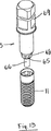
次に、インプラント11と共に使用できるアバットメント12の1つの形を示す図8、9及び10を参照する。アバットメント12は、インプラントの領域31に対応する領域45を含む。この領域45はローブ付形状を含み、該ローブ付形状は、複数の外方に延びる凸状ローブ46を含む複数の外向きローブと、複数の凹状ローブ48からなり、該凸状ローブ46は凹状ローブ38と相補し、これと係合するよう設計されており、該凹状ローブ48は凸状ローブ39と相補し、これと係合するよう設計される。したがって、図1及び2に示すように組み立てたとき、アバットメントのローブ付形状45は領域31のローブ付形状内に挿入され、そこで着座するよう設計される。
Reference is now made to FIGS. 8, 9 and 10 showing one form of
ローブ46及び48の大径円及び小径円を含む寸法は、ローブ38及び39の大径円40及び小径円41に近似し又はこれより若干小さい。また、領域31のローブ付形状のように、ローブ46及び48は側壁を有し、該側壁は互いに実質的に平行に、かつインプラント組立体の縦軸36に対し実質的に平行に延びる。好ましくは、ローブ46及び48の基端側端部49と末端側端部50との間の長さは、ローブ38及び39の対応する長さより若干短い。したがって、ローブ46及び48はそれぞれローブ38及び39中に比較的精密な許容差で摺動するよう設計される。
Dimensions including large-diameter and small-
アバットメント12の末端側端部19は、導入部又は領域53を含み、またこれによって規定され、該領域は傾斜導入面51を含む。この導入面51は、インプラント11のローブ付形状領域31中にアバットメント12のローブ付形状45を案内するに役立つ。アバットメントとインプラントが図2に示す組み立てられた形にあるとき、導入領域53と面51は収容区域44内に収容される(図2、6及び12)。
The
アバットメント12の係止又は安定化部57は、ローブ付形状45の基端側端部49に隣接して位置決めされ、この端49から端54まで延びる。この部分57は傾斜面52を含み、該傾斜面はその基端側端部54から端49に向かって内方に傾斜する。この面52は、実質的に円錐台形の外面であり、インプラント及び、組み立てた時はインプラント組立体、の中心線36に対し角度”B”を形成する、好ましくは、この角度”B”は角度”A”と同一である。しかしながら、本発明の一定の利点は、”A”と”B”が互いに異なる角度であっても達成できる。しかしながら、好ましくは、角度”B”は約8〜40°、より好ましくは8〜30°、最も好ましくは8〜20°である。
A locking or stabilizing
アバットメントの面52の基端側端部54から外方に延びるのは、遠位方向に向いた面55を含む肩部である。この面55は、アール状の角を備えた全体に環状の形状を有する。いくつかのアバットメント形状において、肩部は省略することができる。
Extending outwardly from the proximal end 54 of the
インプラント11内にアバットメント12を組み付けると、図2及び11に最も良く示すように、面52と35は互いに摩擦嵌合係合で係合する。傾斜面52と35との摩擦嵌合は、これらの2つの面間にテーパ係止係合を提供する。これによりアバットメント12とインプラント11との間が安定し、アバットメント12とインプラント11間のどのような揺れや微動も排除され又は減少する。
When the
アバットメント12はさらに、区域57と基端側端部20の間に本体部58を含む。この本体58は人工歯又は他の器具を支持する。貫通孔又はボア17が本体58の一部を貫き、また安定化部57、ローブ付形状45及び導入領域53を貫いて延びる。貫通孔17は、その基端側端部ではボア59によって、またその末端側端部ではボア60によって規定される。ボア59及び60はアバットメントねじ支持肩部61によって連結される。
The
図2に示すようにアバットメントを組み立て患者に装着すると、アバットメントねじ14はボア17を貫いて延び、その雄ねじ24がインプラント11の雌ねじ32と係合する。ねじ14のヘッド22は肩部を含み、該肩部はアバットメントの肩部61と結合し、これに着座する。アバットメントねじ14を肩部61に対し前進させるにつれて、面52は面35に対し押し込まれ、アバットメントのローブ付形状45はインプラントのローブ付形状31内に位置決めされる。
When the abutment is assembled and attached to the patient as shown in FIG. 2, the
図8、9及び10に示す実施の形態のアバットメントは、軸外装填をもたらす事前角度付けアバットメントである。したがって、貫通孔17は、アバットメントの区域53、45及び57と、また組み立てた時はインプラントの縦軸36と整列するが、アバットメントの本体部58と完全には整列しない。アバットメントは様々な形状を取ることができ、様々な角度を備えた事前角度付けアバットメントや、軸外取付用でない又はこれを意図しない真っ直ぐなアバットメントも含まれる。これらの真っ直ぐなアバットメントにおいて、貫通孔17はアバットメントの末端側端部20を貫いて延びる。
The abutment of the embodiment shown in FIGS. 8, 9, and 10 is a pre-angled abutment that provides off-axis loading. Thus, the through-
図13〜16はインプラント11を装着する駆動手段の2つの実施の形態を示す。具体的には、図13及び14は直接駆動の実施の形態を図示し、図15及び16は事前に組み立てられた固定マウントを備えたインプラントを図示する。
13 to 16 show two embodiments of drive means for mounting the
図13及び14を参照すると、直接駆動手段は、ガイド部66、駆動部65、面部68及び回転領域69を含む。ガイド部66は、全体に筒状の、ねじ付でない構造体を備え、該構造体は駆動部材63の縦軸と全体に平行に延びる。領域65は、アバットメントのローブ付形状45(図9)と実質的に一致するローブ付形状を備え、駆動部材63をインプラント11に挿入し回転させると、ローブ付形状65はローブ付形状31と駆動関係で結合し係合する。回転部69は、六角、四角又は他の任意の手段を備えることができ、これに電動式の又は非電動の器械等を適用して駆動部材63を、したがってインプラント11を回転させる。
Referring to FIGS. 13 and 14, the direct driving means includes a
図15及び16は、インプラントと、これに付随する固定マウント組立体を備える事前組立体を示す。組立体はマウント70と保持ねじ71を含む。このアダプタは、アバットメントのローブ付形状(図9)と実質的に一致するローブ付形状73を含み、図16に示すようにマウント70を組み立てられた形でインプラント11に挿入すると、ローブ付形状73はローブ付形状31と駆動関係で結合し係合する。回転部材74は、アダプタ70の基端側端部に形成され、図示のように六角形でも、四角でも又は駆動部材を収容すれば他の任意の形でよい。マウント70は、ねじ71を受け入れるため中央ボア又は貫通孔79を含む。ボア79は、アダプタ70内にねじ71を収めるため雌ねじ部81を含む。ねじは、その末端側端部に雄ねじ部75、細長いシャフト76、及びスロット77又は他の回転手段を備えたヘッド78を含む。
Figures 15 and 16 show a pre-assembly comprising an implant and an associated fixed mount assembly. The assembly includes a
インプラント11に組み付けると、図16に示すように、ローブ付形状73はインプラント11の開口端に挿入され、インプラントの対応するローブ付部分31と結合する。ねじ71をその後ボア79の開口端に挿入し、末端側端部をインプラント11の雌ねじ32にねじ込む。ねじ71を締め付けて、マウント78の下面をマウントの基端側端部80と堅く係合させ、これにより固定マウント組立体をインプラント11内にしっかりと固着する。
When assembled to the
本発明の歯科インプラント及び歯科インプラント組立体の構造を説明してきたが、その装着は最良には次のように理解することができる。まず、患者の口腔内にインプラントの場所を準備した後、図13及び14に示すような直接駆動部材63により、又は図15及び16に示す事前組立の固定マウントにより、インプラントを回転させて装着する。インプラントを所望の装着深さに装着した後、駆動部材63又は固定マウント組立体をインプラントから取り外す。アバットメントをその後インプラントの開口端内に位置決めし、アバットメントのローブ付形状45及び面52をインプラントのローブ付形状31及び面35内に位置決めして係合させる。アバットメントねじ14をその後ボア17の開口端に挿入し、ラチェット又はこの技術分野で知られた他の回転用具で回転させる。ねじ14の回転により、傾斜面52は傾斜面35に押しつけられ、堅い摩擦嵌合を形成する。これにより、アバットメントとインプラントの間に安定性が提供される。
Having described the structure of the dental implant and dental implant assembly of the present invention, its mounting can best be understood as follows. First, after preparing the location of the implant in the patient's mouth, the implant is rotated and mounted by a direct drive member 63 as shown in FIGS. 13 and 14 or by a pre-assembled fixed mount as shown in FIGS. . After mounting the implant to the desired mounting depth, the drive member 63 or fixed mount assembly is removed from the implant. The abutment is then positioned within the open end of the implant and the
本実施の形態の説明はかなり具体的であるが、本発明の精神から逸脱することなく様々な改変を加えることができると考えられる。それ故、本発明の範囲は本実施の形態の説明によってでなく添付の特許請求の範囲によって決定されるべきと考えられる。 Although the description of this embodiment is fairly specific, it is believed that various modifications can be made without departing from the spirit of the invention. Therefore, the scope of the present invention should be determined not by the description of the embodiments but by the appended claims.
Claims (18)
縦軸(36)、基端側端部(proximal end)(16)及び末端側端部(distal end)(15)を有する本体(13)と、
前記本体(13)の外側部分に設けられたインプラント保持手段(18)と、
前記本体(13)の一部分内に設けられた内部ボア(32)であって、前記本体(13)の基端側端部(16)に一致する内部ボア基端側端部(16)、及び内部ボア末端側端部を有する前記内部ボア(32)と、
基端側端部(16)及び末端側端部(33)を有する円錐台形の内向き面(35)であって、前記内部ボア(32)の基端側端部(16)の近くから前記内部ボア(32)の末端側端部(42)に向けて延び、かつ該本体(13)の末端側端部(15)に向けて内方に斜面とされた内向き面(35)であって、該内向き面(35)が末端側端部(15)へ向けて前記縦軸(36)に対して内方へ傾斜する角度は8°〜40°である前記円錐台形の内向き面(35)と、
前記面(35)の末端側端部(33)と前記内部ボア(32)の末端側端部との間にて前記内部ボア(32)内に配置された内向きの駆動領域(31)であって、複数の凹状ローブ(38)と、前記凹状ローブ(38)と互い違いに配置された複数の凸状ローブ(39)とを含み、凹状ローブ(38)の各々の半径方向最外点は、大径円(40)上に位置し、前記凸状ローブ(39)の各々の半径方向最内点は、小径円(41)上に位置し、前記凹状ローブ(38)の各々の少なくとも一部分は、円形の形状を有し、前記凸状のローブ(39)の各々の少なくとも一部分は、円形の形状を有する前記内向きの駆動領域(31)と、
前記内部ボア(32)内にてかつ前記駆動領域(31)の末端側端部(42)と前記内部ボア(32)の末端側端部との間に配置された円筒状の収容領域(44)であって、前記小径円(41)より小さい収容領域(44)の直径を規定する内向きの円筒状面を含む前記円筒状の収容領域(44)と、
前記内部ボア(32)内にてかつ前記収容領域(44)と前記本体(13)の末端側端部(15)との間に配置された雌ねじ付き部分(32)であって、前記収容領域(44)の直径よりも小さい直径を有する前記雌ねじ付き部分(32)とを備える、歯科インプラント。In the dental implant (11)
A body (13) having a longitudinal axis (36), a proximal end (16) and a distal end (15);
Implant retaining means (18) provided on the outer part of the body (13);
An inner bore (32) provided within a portion of the body (13), the inner bore proximal end (16) coinciding with the proximal end (16) of the body (13); and Said internal bore (32) having an internal bore distal end;
A frustoconical inward surface (35) having a proximal end (16) and a distal end (33) , from near the proximal end (16) of the internal bore (32); It extends toward the distal end (42) of the inner bore (32), and met the distal end (15) is a slope inwardly towards the inner facing surface of the body (13) (35) The angle of inward inclination of the inward surface (35) toward the distal end (15) with respect to the longitudinal axis (36) is 8 ° to 40 °. (35) and
An inward drive region (31) disposed in the internal bore (32) between the distal end (33) of the face (35) and the distal end of the internal bore (32) A plurality of concave lobes (38), and a plurality of convex lobes (39) arranged alternately with the concave lobes (38), and each radially outermost point of the concave lobes (38) is , Located on the large diameter circle (40), and the radially innermost point of each of the convex lobes (39) is located on the small diameter circle (41) and is at least a portion of each of the concave lobes (38). Has a circular shape and at least a portion of each of the convex lobes (39) has the inward drive region (31) having a circular shape ;
A cylindrical housing region (44) disposed within the inner bore (32) and between the distal end (42) of the drive region (31) and the distal end of the inner bore (32). The cylindrical containment region (44) including an inwardly cylindrical surface defining a diameter of the containment region (44 ) smaller than the small diameter circle (41) ;
A female threaded portion (32) disposed within the internal bore (32) and between the receiving area (44) and the distal end (15) of the body (13), wherein the receiving area Said internal threaded portion (32) having a diameter smaller than the diameter of (44).
前記複数の凸状ローブ(39)の各々の全体は、円形の形状のセグメントにより規定され、前記複数の凹状ローブ(38)の各々の全体は、円形の形状のセグメントにより規定される、歯科インプラント。Dental implant (11) according to claim 1,
Each of the plurality of convex lobes (39) is defined by a circular shaped segment, and each of the plurality of concave lobes (38) is defined by a circular shaped segment. .
前記凹状ローブ(38)の各々の円形の形状は、単一の円形のセグメントから成り、前記凸状ローブ(39)の各々の円形の形状は、単一の円形のセグメントから成る、歯科インプラント。Dental implant (11) according to claim 2,
A dental implant wherein each circular shape of the concave lobe (38) consists of a single circular segment and each circular shape of the convex lobe (39) consists of a single circular segment.
前記収容領域(44)の直径は、前記小径円(41)の直径と同一である、歯科インプラント。Dental implant (11) according to claim 1,
The diameter of the receiving area (44) is the same as the diameter of the small diameter circle (41).
前記凹状ローブ(38)及び前記凸状ローブ(39)の各々の全体は、円形の形状から成る、歯科インプラント。Dental implant (11) according to claim 1,
A dental implant wherein each of the concave lobe (38) and the convex lobe (39) is of a circular shape.
該歯科インプラント組立体は、(a)歯科インプラント(11)と、(b)前記歯科インプラント(11)と選択的に接続可能なアバットメント(12)と、(c)アバットメントねじ(14)とを備え、
(a) 前記歯科インプラント(11)は、
縦軸(36)、末端側端部(17)及び開口した基端側端部(16)を有する本体(13)と、
前記本体(13)の外側部分に設けられたインプラント保持手段(18)と、
前記本体(13)の一部分内に設けられた内部ボア(32)であって、前記本体(13)の開口基端側端部(16)に一致する基端側端部(16)と、内部ボア(32)の末端側端部と、を有する前記内部ボア(32)と、
基端側端部(16)及び末端側端部(33)を有する円錐台形の内向き面(35)であって、前記内部ボア(32)の基端側端部(16)の近くから前記内部ボア(32)の末端側端部(42)に向けて延び、かつ該本体(13)の末端側端部(15)に向けて内方に斜面とされた内向き面(35)であって、該内向き面(35)が末端側端部(15)へ向けて前記縦軸(36)に対して内方へ傾斜する角度は8°〜40°である前記円錐台形の内向き面(35)と、
前記内部ボア(32)内に前記円錐台形の内向き面(35)と前記内部ボア(32)の末端側端部(42)との間で配置された内向きの駆動領域(31)であって、複数の凹状ローブ(38)と、前記凹状ローブ(38)と互い違いに配置された複数の凸状ローブ(39)とを含み、凹状ローブ(38)の各々の半径方向最外点は、大径円(40)上に位置し、前記凸状ローブ(39)の各々の半径方向最内点は、小径円(41)上に位置し、前記凹状ローブ(38)の各々の少なくとも一部分は、円形の形状を有し、前記凸状のローブ(39)の各々の少なくとも一部分は、円形の形状を有する前記内向きの駆動領域(31)と、
前記内部ボア(32)内にてかつ前記駆動領域(31)の末端側端部(42)と前記内部ボア(32)の末端側端部との間に配置された円筒状の収容領域(44)であって、前記小径円より小さい収容領域(44)の直径を規定する内向きの円筒状面を含む前記円筒状の収容領域(44)と、
前記内部ボア(32)の末端側端部における雌ねじ付き領域(32)であって、前記収容領域(44)の直径よりも小さい直径を有する前記雌ねじ付き部分(32)とを備え、
(b)前記アバットメント(12)は、
基端側端部(49)と、末端側端部(50)と、
前記歯科インプラント(11)及び前記アバットメント(12)が接続されたとき、前記内向き面(35)に係合するよう配置された傾斜面(52)と、
前記歯科インプラント(11)及び前記アバットメント(12)が接続されたとき、前記駆動領域(31)に相応しかつ前記駆動領域(31)に隣接するアバットメント領域(45)であって、前記駆動領域(31)の前記凹状ローブ(38)及び凸状ローブ(39)にそれぞれ相応する複数の凸状ローブ(46)及び複数の凹状ローブ(48)を含む前記アバットメント領域(45)と、
補綴物取り付け部(58)と、
前記補綴物取り付け部分(58)の少なくとも一部分を貫いて延びる中央ボア(60)とを備え、
(c)前記アバットメントねじ(14)は、前記歯科インプラント(11)、前記アバットメント(12)及び該アバットメントねじ(14)が、前記アバットメントねじ(14)が前記アバットメント(12)の中央ボア(60)を貫いて前記歯科インプラント(11)の前記雌ねじ付き領域(32)内に延び、且つ前記アバットメント(12)の傾斜面(52)及び前記歯科インプラント(11)の内向き面(35)がこれらの二つの表面の間で摩擦嵌合係合で互いに係合して、安定性を提供し且つ前記アバットメント(12)と前記歯科インプラント(11)との間の揺れ又は微動を排除又は減少させるような形状とされている、歯科インプラント組立体。A dental implant assembly comprising:
The dental implant assembly includes: (a) a dental implant (11); (b) an abutment (12) selectively connectable to the dental implant (11); and (c) an abutment screw (14). With
(A) The dental implant (11)
A body (13) having a longitudinal axis (36), a distal end (17) and an open proximal end (16);
Implant retaining means (18) provided on the outer part of the body (13);
An inner bore (32) provided within a portion of the body (13), the proximal end (16) coinciding with the open proximal end (16) of the body (13); The inner bore (32) having a distal end of the bore (32);
A frustoconical inward surface (35) having a proximal end (16) and a distal end (33), from near the proximal end (16) of the internal bore (32); An inwardly facing surface (35) extending towards the distal end (42) of the inner bore (32) and sloped inwardly toward the distal end (15) of the body (13). The angle of inward inclination of the inward surface (35) toward the distal end (15) with respect to the longitudinal axis (36) is 8 ° to 40 °. (35) and
An inward drive region (31) disposed within the internal bore (32) between the frustoconical inward surface (35) and the distal end (42) of the internal bore (32). A plurality of concave lobes (38) and a plurality of convex lobes (39) arranged alternately with the concave lobes (38), and the radially outermost point of each concave lobe (38) is: Located on the large diameter circle (40), the radially innermost point of each of the convex lobes (39) is located on the small diameter circle (41) and at least a portion of each of the concave lobes (38) is And at least a portion of each of the convex lobes ( 39 ) has a circular shape and the inward drive region (31) having a circular shape ;
A cylindrical housing region (44) disposed within the inner bore (32) and between the distal end (42) of the drive region (31) and the distal end of the inner bore (32). The cylindrical containment region (44) including an inwardly cylindrical surface defining a diameter of the containment region (44) smaller than the small diameter circle ;
A female threaded region (32) at the distal end of the inner bore (32), the female threaded portion (32) having a diameter smaller than the diameter of the receiving region (44);
(B) The abutment (12)
A proximal end (49), a distal end (50),
An inclined surface (52) arranged to engage the inwardly facing surface (35) when the dental implant (11) and the abutment (12) are connected;
An abutment region (45) corresponding to the drive region (31) and adjacent to the drive region (31) when the dental implant (11) and the abutment (12) are connected, the drive The abutment region (45) including a plurality of convex lobes (46) and a plurality of concave lobes (48) corresponding respectively to the concave lobes (38) and convex lobes (39) of the region (31);
A prosthetic attachment (58);
A central bore (60) extending through at least a portion of the prosthesis mounting portion (58);
(C) The abutment screw (14) is the dental implant (11), the abutment (12) and the abutment screw (14), and the abutment screw (14) is the abutment screw (12). Extending through the central bore (60) into the internal threaded region (32) of the dental implant (11) and the inclined surface (52) of the abutment (12) and the inwardly facing surface of the dental implant (11) (35) engage each other in a friction fit engagement between these two surfaces to provide stability and sway or tremor between the abutment (12) and the dental implant (11) A dental implant assembly that is shaped to eliminate or reduce .
前記アバットメント領域(45)の直径は、前記収容領域(44)の直径よりも小さい、歯科インプラント組立体。The dental implant assembly according to claim 6,
A dental implant assembly, wherein the diameter of the abutment region (45) is smaller than the diameter of the receiving region (44).
前記内向き面(35)は、前記末端側端部(15)へ向けて前記縦軸(36)に対して12°〜20°の角度で傾斜している、歯科インプラント組立体。The dental implant assembly according to claim 6,
Dental implant assembly wherein the inwardly facing surface (35) is inclined at an angle of 12 ° to 20 ° relative to the longitudinal axis (36) towards the distal end (15) .
前記アバットメント(12)の傾斜面(52)は、前記縦軸(36)に対して12°〜20°の角度で傾斜している、歯科インプラント組立体。The dental implant assembly according to claim 8,
The dental implant assembly, wherein the inclined surface (52 ) of the abutment (12) is inclined at an angle of 12 ° to 20 ° with respect to the longitudinal axis (36) .
前記内向き面(35)は、前記縦軸(36)に対して12°〜20°の角度で傾斜している、歯科インプラント。Dental implant (11) according to claim 1,
Dental implant wherein the inwardly facing surface (35) is inclined at an angle of 12 ° to 20 ° with respect to the longitudinal axis (36).
前記円錐台形の内向き面(35)は、その基端側端部の所定の直径寸法、及び所定の長さ寸法を有し、該所定の直径寸法は前記縦軸(36)に対して直交する方向に測定され、又前記所定の長さ寸法は前記縦軸(36)に平行な方向に測定され、かつ前記長さ寸法は前記直径寸法の15%〜40%の範囲にある、歯科インプラント。Dental implant (11) according to claim 1,
The frustoconical inward surface (35) has a predetermined diameter dimension and a predetermined length dimension at its proximal end, and the predetermined diameter dimension is orthogonal to the longitudinal axis (36). And the predetermined length dimension is measured in a direction parallel to the longitudinal axis (36) and the length dimension is in the range of 15% to 40% of the diameter dimension. .
前記円錐台形の内向き面(35)は、その基端側端部の所定の直径寸法、及び所定の長さ寸法を有し、該所定の直径寸法は前記縦軸(36)に対して直交する方向に測定され、又前記所定の長さ寸法は前記縦軸(36)に平行な方向に測定され、かつ前記長さ寸法は前記直径寸法の15%〜40%の範囲にある、歯科インプラント組立体。The dental implant assembly according to claim 6 ,
The frustoconical inward surface (35) has a predetermined diameter dimension and a predetermined length dimension at its proximal end, and the predetermined diameter dimension is orthogonal to the longitudinal axis (36). And the predetermined length dimension is measured in a direction parallel to the longitudinal axis (36) and the length dimension is in the range of 15% to 40% of the diameter dimension. Assembly.
前記大径円(40)は、前記直径寸法の60%〜90%の範囲にある、歯科インプラント。The dental implant according to claim 11 ,
The large diameter circle (40) is a dental implant in the range of 60% to 90% of the diameter dimension .
前記大径円(40)は、前記直径寸法の60%〜90%の範囲にある、歯科インプラント組立体。Dental implant assembly wherein the large diameter circle (40) is in the range of 60% to 90% of the diameter dimension.
前記長さ寸法は、前記直径寸法の15%〜25%の範囲にある、歯科インプラント。A dental implant wherein the length dimension is in the range of 15% to 25% of the diameter dimension.
前記長さ寸法は、前記直径寸法の15%〜25%の範囲にある、歯科インプラント組立体。Dental implant assembly wherein the length dimension is in the range of 15% to 25% of the diameter dimension.
前記複数の凹状ローブ(38)の各々の円形状の直径は、複数の凸状ローブ(39)の各々の円形状の直径と同一である、歯科インプラント。A dental implant wherein the circular diameter of each of the plurality of concave lobes (38) is the same as the circular diameter of each of the plurality of convex lobes (39).
前記複数の凹状ローブ(38)の各々の円形状の直径は、複数の凸状ローブ(39)の各々の円形状の直径と同一である、歯科インプラント組立体。The dental implant assembly wherein the circular diameter of each of the plurality of concave lobes (38) is the same as the circular diameter of each of the plurality of convex lobes (39).
Applications Claiming Priority (3)
| Application Number | Priority Date | Filing Date | Title |
|---|---|---|---|
| US10/879,824 | 2004-06-29 | ||
| US10/879,824 US7249949B2 (en) | 2004-06-29 | 2004-06-29 | Internal connection dental implant |
| PCT/US2005/022403 WO2006012273A1 (en) | 2004-06-29 | 2005-06-23 | Internal connection dental implant |
Publications (3)
| Publication Number | Publication Date |
|---|---|
| JP2008504883A JP2008504883A (en) | 2008-02-21 |
| JP2008504883A5 JP2008504883A5 (en) | 2008-07-31 |
| JP4886683B2 true JP4886683B2 (en) | 2012-02-29 |
Family
ID=34982347
Family Applications (1)
| Application Number | Title | Priority Date | Filing Date |
|---|---|---|---|
| JP2007519300A Active JP4886683B2 (en) | 2004-06-29 | 2005-06-23 | Internally connected dental implant |
Country Status (18)
| Country | Link |
|---|---|
| US (1) | US7249949B2 (en) |
| EP (1) | EP1763324B2 (en) |
| JP (1) | JP4886683B2 (en) |
| KR (1) | KR101168454B1 (en) |
| CN (2) | CN102512254B (en) |
| AT (1) | ATE447901T1 (en) |
| AU (1) | AU2005267241B2 (en) |
| BR (1) | BRPI0509047B8 (en) |
| CA (1) | CA2562696C (en) |
| DE (1) | DE602005017623D1 (en) |
| DK (1) | DK1763324T4 (en) |
| ES (1) | ES2335510T5 (en) |
| HK (1) | HK1104447A1 (en) |
| IL (1) | IL178624A (en) |
| MX (1) | MXPA06012226A (en) |
| PL (1) | PL1763324T5 (en) |
| PT (1) | PT1763324E (en) |
| WO (1) | WO2006012273A1 (en) |
Families Citing this family (97)
| Publication number | Priority date | Publication date | Assignee | Title |
|---|---|---|---|---|
| US2674641A (en) * | 1950-04-25 | 1954-04-06 | Milwaukee Gas Specialty Co | Thermoelectric generator and method for production of same |
| SE520043C2 (en) * | 2001-09-06 | 2003-05-13 | Nobel Biocare Ab | Implants and tightening and spacer means for such implants |
| SE523395C2 (en) | 2001-12-21 | 2004-04-13 | Nobel Biocare Ab | Implants and methods and systems for providing such implants |
| SE520756C2 (en) | 2001-12-21 | 2003-08-19 | Nobel Biocare Ab | Method of providing surface structure on implants as well as such implants |
| SE526667C2 (en) * | 2002-12-30 | 2005-10-25 | Nobel Biocare Ab | Device for implants and method for making the implant |
| IL156033A0 (en) | 2003-05-21 | 2004-03-28 | Ophir Fromovich Ophir Fromovic | Dental implant |
| ES2307352B1 (en) * | 2005-04-12 | 2009-09-18 | Bti, I+D, S.L. | DENTAL IMPLANT AND PARTS INTENDED TO BE CONNECTED TO A DENTAL IMPLANT, AND THE INTERNAL CONNECTION BETWEEN THE DENTAL IMPLANT AND EACH PIECE. |
| EP1728486A1 (en) | 2005-06-03 | 2006-12-06 | Straumann Holding AG | Coupling for a multi-part dental implant system |
| US20070037121A1 (en) | 2005-08-10 | 2007-02-15 | Carter Robert D | Carry and drive device and method for dental implant and/or components thereof |
| DE202006020210U1 (en) | 2006-02-02 | 2008-02-07 | Friadent Gmbh | Arrangement for insertion of implants |
| US7780446B2 (en) * | 2006-02-24 | 2010-08-24 | Zimmer Dental, Inc. | Ceramic/metallic dental abutment |
| ES2315100B1 (en) * | 2006-05-23 | 2010-01-05 | Vogul, S.L. | DENTAL IMPLANT OF INTERNAL CONE. |
| EP1915970A1 (en) * | 2006-07-20 | 2008-04-30 | René De Clerck | Jig for positioning dental implants |
| KR101173964B1 (en) * | 2006-12-14 | 2012-08-16 | 프리아덴트 게엠베하 | Arrangement for insertion of implants |
| US9095397B2 (en) | 2006-12-14 | 2015-08-04 | Friadent Gmbh | Arrangement for insertion of implants |
| US9308031B2 (en) | 2007-01-26 | 2016-04-12 | Biomet Manufacturing, Llc | Lockable intramedullary fixation device |
| US9320551B2 (en) | 2007-01-26 | 2016-04-26 | Biomet Manufacturing, Llc | Lockable intramedullary fixation device |
| US8157802B2 (en) * | 2007-01-26 | 2012-04-17 | Ebi, Llc | Intramedullary implant with locking and compression devices |
| CN100571651C (en) * | 2007-04-12 | 2009-12-23 | 赵大国 | A kind of bionic tooth implant |
| US8038442B2 (en) * | 2007-04-23 | 2011-10-18 | Nobel Biocare Services Ag | Dental implant and dental component connection |
| US7806693B2 (en) * | 2007-04-23 | 2010-10-05 | Nobel Biocare Services Ag | Dental implant |
| WO2009015103A1 (en) | 2007-07-20 | 2009-01-29 | Cochlear Americas | Coupling apparatus for a bone anchored hearing device |
| CN101827560A (en) * | 2007-10-16 | 2010-09-08 | Ebi有限责任公司 | Method and apparatus for orthopedic fixation |
| US20090111072A1 (en) * | 2007-10-30 | 2009-04-30 | Alan Lombardo | Dental implant and abutment mating system |
| EP2090263A1 (en) * | 2008-02-13 | 2009-08-19 | Straumann Holding AG | Abutment with inlay for dental implants |
| DE102008011963A1 (en) * | 2008-02-29 | 2009-09-10 | Axel Cyron | Dental implant and process for its preparation |
| EP2106767A1 (en) | 2008-03-31 | 2009-10-07 | Ziterion GmbH | Two-part dental implant |
| US20090298014A1 (en) * | 2008-05-28 | 2009-12-03 | Global Implant Solutions, Llc | Dental Implant |
| CZ303431B6 (en) * | 2008-10-23 | 2012-09-12 | Podešva@Pavel | System for fixing prosthetic superstructure to solid body environment and process for producing thereof |
| US20100119993A1 (en) * | 2008-11-11 | 2010-05-13 | Cagenix, Inc. | Dental implant |
| JP2010207276A (en) * | 2009-03-06 | 2010-09-24 | Gc Corp | Wax model table for abutment of dental implant |
| BE1018492A3 (en) | 2009-06-02 | 2011-01-11 | Layerwise N V | |
| EP2347729A1 (en) * | 2010-01-21 | 2011-07-27 | Camlog Biotechnologies AG | Dental implant, abutment for a dental implant, combination of the same and an implantation set |
| CH703012B1 (en) * | 2010-04-27 | 2014-08-29 | New Dent Ag | Dental implant. |
| US8439932B2 (en) | 2010-05-03 | 2013-05-14 | Biomet Manufacturing Corp. | Submuscular plating system |
| PL2566413T3 (en) | 2010-05-05 | 2017-07-31 | Holger Zipprich | Dental implant |
| EP2407120A1 (en) * | 2010-07-14 | 2012-01-18 | Nobel Biocare Services AG | Implant system |
| EP2407121A1 (en) * | 2010-07-14 | 2012-01-18 | Nobel Biocare Services AG | Abutment system |
| CN202843827U (en) * | 2010-10-12 | 2013-04-03 | 西安中邦种植体技术有限公司 | Oral implant carrying wrench |
| CN101947139B (en) | 2010-10-21 | 2013-10-23 | 赵大国 | Bionic dental implant and abutment and seminal root thereof |
| DE102010051176A1 (en) | 2010-11-15 | 2012-05-16 | Urs Brodbeck | Dental implant system and method for producing a dental implant system |
| ES2557581T3 (en) | 2010-12-23 | 2016-01-27 | Straumann Holding Ag | Enhanced Screw Head |
| DE102011009906A1 (en) | 2011-01-31 | 2012-08-02 | Holger Zipprich | Dental implant system |
| US9283057B2 (en) * | 2011-02-02 | 2016-03-15 | Mid Corp. | System, apparatus and method for implementing implants |
| US20120237899A1 (en) * | 2011-03-03 | 2012-09-20 | Astra Tech Ab | Dental implant assembly |
| FR2972625B1 (en) † | 2011-03-15 | 2014-02-28 | Biotech Internat | DENTAL IMPLANT |
| EP2502600A1 (en) * | 2011-03-21 | 2012-09-26 | Biodenta Swiss AG | Dental implant system |
| AT511387B1 (en) | 2011-04-20 | 2013-02-15 | Redtenbacher Praez Steile Ges M B H | DENTAL PROSTHESIS |
| US20120288826A1 (en) * | 2011-05-11 | 2012-11-15 | Fitton Iii Russell P | Dental Implants and Methods for Their Insertion into Patients |
| WO2012156960A1 (en) * | 2011-05-18 | 2012-11-22 | Ilya Mushayev | Universal angulated abutment |
| KR101093512B1 (en) | 2011-05-26 | 2011-12-13 | 염명희 | Abutment material |
| US8684735B2 (en) * | 2011-12-06 | 2014-04-01 | Straumann Holding Ag | Abutment inlay |
| TW201322963A (en) * | 2011-12-12 | 2013-06-16 | Rong-Yan Liao | Dental implant retaining and positioning system |
| FR2985419B1 (en) * | 2012-01-05 | 2016-07-01 | Gilbert Ouaknine | INLAY CORE FIXING WITH DENTAL IMPLANT |
| BR102012029369A2 (en) | 2012-11-19 | 2014-09-23 | Esteban Xam-Mar Mangrane | IMPROVEMENTS INTRODUCED IN DYNAMIC PILLAR ASSEMBLY |
| TWI487510B (en) * | 2012-11-20 | 2015-06-11 | Chih Chung Ho | An implant having a first internal thread and a second internal thread |
| EP2931167B1 (en) | 2012-12-11 | 2019-03-06 | Kulzer GmbH | One-part or multi-part implant system comprising a mounting element having one or more outer rings |
| USD767763S1 (en) * | 2013-02-11 | 2016-09-27 | A.B. Dental Devices Ltd. | Dental connector assembly |
| CN105208965B (en) | 2013-03-15 | 2018-10-16 | 捷迈齿科有限公司 | With the dental implant for improving prosthese interface |
| USD731655S1 (en) | 2013-03-15 | 2015-06-09 | Benedict Lui | Dental implant abutment |
| CN103271774A (en) * | 2013-06-07 | 2013-09-04 | 大连三生科技发展有限公司 | Micro screw implant |
| CN103263303A (en) * | 2013-06-07 | 2013-08-28 | 大连三生科技发展有限公司 | Dental implant device |
| USD732169S1 (en) | 2013-09-16 | 2015-06-16 | Benedict Lui | Dental implant abutment |
| CN103550004B (en) * | 2013-11-18 | 2016-08-17 | 大连三生科技发展有限公司 | Implanting body of artificial tooth and implanting body of artificial tooth system |
| DE102014118723A1 (en) * | 2013-12-17 | 2015-06-18 | Epiphanostics GmbH | Enossal single-tooth implant |
| US10470851B2 (en) | 2013-12-24 | 2019-11-12 | Straumann Holding Ag | Self-retaining dental screw |
| US11240613B2 (en) | 2014-01-30 | 2022-02-01 | Cochlear Limited | Bone conduction implant |
| USD752753S1 (en) * | 2014-03-17 | 2016-03-29 | Implant Direct Sybron International L.L.C. | Dental prosthesis |
| USD752756S1 (en) * | 2014-03-17 | 2016-03-29 | Implant Direct Sybron International L.L.C. | Dental prosthesis |
| USD752754S1 (en) * | 2014-03-17 | 2016-03-29 | Implant Direct Sybron International L.L.C. | Dental prosthesis |
| USD752755S1 (en) * | 2014-03-17 | 2016-03-29 | Implant Direct Sybron International L.L.C. | Dental prosthesis |
| TWI571246B (en) * | 2014-07-10 | 2017-02-21 | 財團法人金屬工業研究發展中心 | A dental prosthesis and a dental implant thereof |
| US10292792B2 (en) | 2014-08-29 | 2019-05-21 | Nobel Biocare Services Ag | Restoration dental implant and method |
| US11090138B2 (en) | 2014-08-29 | 2021-08-17 | Fereidoun Daftary | Dental implant system and method |
| US9757215B2 (en) * | 2014-09-16 | 2017-09-12 | Froncare | Dental sinus lift device for implant rehabilitation |
| DE102014016081B4 (en) * | 2014-11-03 | 2018-05-03 | Curd Gadau | ABUTMENTAUFSATZ |
| BR102014031426B1 (en) | 2014-12-15 | 2018-07-24 | Jjgc Ind E Comercio De Materiais Dentarios S/A | implant |
| CL2015001657S1 (en) | 2014-12-15 | 2016-09-02 | Jjgc Indústria E Comércio De Materiais Dentários S A | Configuration applied to bone implant. |
| DE102015100117B4 (en) * | 2015-01-07 | 2018-12-13 | Johannes Scherer | SYSTEM AND DENTAL IMPLANT TO REDUCE DENTAL IMPLANT AND DENTAL LOSSES |
| USD765860S1 (en) * | 2015-03-05 | 2016-09-06 | Fereidoun Daftary | Dental implant |
| WO2017085288A1 (en) * | 2015-11-20 | 2017-05-26 | Nobel Biocare Services Ag | Healing cap with scannable features |
| ITUA20161638A1 (en) * | 2016-03-14 | 2017-09-14 | Sweden & Martina Spa | IMPROVED DENTAL PLANT SYSTEM |
| BR102016010184B1 (en) | 2016-05-05 | 2020-10-27 | Jjgc Indústria E Comércio De Materiais Dentários S.A. | prosthetic set and process for producing the same |
| DE102016008669B4 (en) * | 2016-07-20 | 2018-10-11 | Bruno Spindler | Suprastructure carrier with special implant post geometry |
| KR101907489B1 (en) * | 2016-08-31 | 2018-10-12 | 이모세 | Bone screw for orthopedic surgery |
| RU2017102870A (en) | 2017-01-27 | 2018-07-27 | Никита Сергеевич Черновол | DENTAL IMPLANT |
| EP3398553A1 (en) | 2017-05-02 | 2018-11-07 | Ophir Fromovich | Improved dental implant system |
| RU2695772C2 (en) * | 2017-07-17 | 2019-07-25 | Никита Сергеевич Черновол | Implant set for implantation |
| ES2874257T3 (en) * | 2017-09-12 | 2021-11-04 | Straumann Holding Ag | Improved tissue level implant |
| MX2020013149A (en) * | 2018-06-04 | 2021-02-18 | Implant Protesis Dental 2004 S L | Assembly for forming an interface part for dental implants with variable height. |
| CN110720997A (en) * | 2018-07-17 | 2020-01-24 | 光弘生医科技股份有限公司 | Improvement of tooth root structure |
| CH715768A2 (en) * | 2019-01-22 | 2020-07-31 | Z Systems Ag | Occlusal screw, dental implant system and set. |
| LU101149B1 (en) * | 2019-03-11 | 2020-09-18 | Jade Finance S A R L | Tool assembly for mounting of a dental prosthesis an method of mounting |
| RU197545U1 (en) * | 2019-04-29 | 2020-05-13 | Никита Сергеевич Черновол | DENTAL IMPLANT |
| EP3763322A1 (en) * | 2019-07-10 | 2021-01-13 | Tech Xika PTT, S.L. | Prosthetic dental screw, tightening tool and coupling system between the two |
| USD906522S1 (en) * | 2019-09-26 | 2020-12-29 | Megagen Implant Co., Ltd. | Dental fixture operating connector |
| KR102304081B1 (en) * | 2020-12-30 | 2021-09-24 | 오스템임플란트 주식회사 | Abutment for implant, and coupling structure of fixture and the same |
Family Cites Families (38)
| Publication number | Priority date | Publication date | Assignee | Title |
|---|---|---|---|---|
| US3125910A (en) * | 1964-03-24 | Kavalar | ||
| US3584667A (en) * | 1966-09-19 | 1971-06-15 | Textron Inc | Coupling arrangement and tools for same |
| FR2560099B1 (en) * | 1984-02-24 | 1986-10-24 | Facom | TIGHTENING TOOL FOR HARDWARE |
| US5219392A (en) * | 1985-12-18 | 1993-06-15 | Josef Ruzicka | Rotary wrenching tool |
| GB2199626B (en) * | 1987-01-08 | 1991-09-04 | Core Vent Corp | Screw-type dental implant anchor |
| EP0279004B1 (en) * | 1987-02-17 | 1989-07-12 | Hewlett-Packard GmbH | Method for manufacturing a measuring probe |
| US5030095A (en) * | 1989-08-16 | 1991-07-09 | Niznick Gerald A | Angled abutment for endosseous implants |
| US5334024A (en) * | 1990-03-21 | 1994-08-02 | Core-Vent Corporation | Transfer abutment |
| US5350302A (en) * | 1990-07-05 | 1994-09-27 | Marlin Gerald M | Implant collar and post system |
| US5207132A (en) * | 1991-10-16 | 1993-05-04 | Textron Inc. | Elliptical lobed drive system |
| AU3803193A (en) * | 1991-12-30 | 1994-09-26 | Wellesley Research Associates, Inc. | Dental implant system and apparatus |
| JPH0728877B2 (en) * | 1992-12-11 | 1995-04-05 | 株式会社青山製作所 | Denture implant |
| DE4342058A1 (en) * | 1993-12-09 | 1995-06-22 | Eberle Medizintech Elemente | Endosseous single tooth implant |
| US5810589A (en) * | 1995-03-10 | 1998-09-22 | Dentistry Researchers & Designers Inc. | Dental implant abutment combination that reduces crestal bone stress |
| DE19534979C1 (en) * | 1995-09-20 | 1997-01-09 | Imz Fertigung Vertrieb | Endosseous single tooth implant with anti-rotation device |
| US5681167A (en) * | 1996-01-05 | 1997-10-28 | Lazarof; Sargon | Dental assembly and process for preparing a tooth prosthesis |
| FR2747031B1 (en) † | 1996-04-09 | 1998-05-22 | Serf Sa | DENTAL IMPLANT FOR CARRYING OUT AN IMPLANTATION IN A SURGICAL TIME |
| SE507360C2 (en) * | 1996-09-24 | 1998-05-18 | Nobel Biocare Ab | Device for systems with assortment of dental screws and assortment of dental screws |
| US5782918A (en) * | 1996-12-12 | 1998-07-21 | Folsom Metal Products | Implant abutment system |
| BR9809683A (en) * | 1997-05-24 | 2000-10-03 | Friadent Gmbh | Dental implant and device with a dental implant |
| WO1999052464A1 (en) | 1998-04-08 | 1999-10-21 | Imz Fertigungs- Und Vertriebsgesellschaft Für Dentale Technologie Mbh | Intraosseous single-tooth implant |
| US6250922B1 (en) * | 1998-07-30 | 2001-06-26 | Sulzer Dental Inc. | Two-piece dental abutment with removable cuff |
| SE513111C2 (en) * | 1998-11-11 | 2000-07-10 | Nobel Biocare Ab | Threaded implant and device and method for such an implant |
| IT1307923B1 (en) * | 1999-01-25 | 2001-11-29 | Hofmann S A S Di Roberto Hofma | ENDOSSEO DENTAL IMPLANT DEVICE. |
| US6394806B1 (en) * | 1999-09-14 | 2002-05-28 | Nobel Biocare Usa, Inc | Snap-in healing cap |
| US6733291B1 (en) * | 1999-09-27 | 2004-05-11 | Nobel Biocare Usa, Inc. | Implant with internal multi-lobed interlock |
| ATE424781T1 (en) | 2000-01-04 | 2009-03-15 | Straumann Holding Ag | ENOSSAL DENTAL IMPLANT |
| US6758672B2 (en) * | 2000-01-18 | 2004-07-06 | Implant Innovations, Inc. | Preparation coping for creating an accurate permanent post to support a final prosthesis and method for creating the same |
| USD446859S1 (en) * | 2000-05-18 | 2001-08-21 | Nobel Biocare Usa, Inc. | Multi-lobed dental implant |
| IT1317364B1 (en) | 2000-09-12 | 2003-06-16 | Vincenzo Crudo | PERFECTED IMPLANT FOR FASTENING DENTAL PROSTHESES. |
| US20070037123A1 (en) * | 2000-10-26 | 2007-02-15 | Mansueto Robert F | High-strength dental-implant w/curvilinear-indexing and tool-free delivery-system |
| US6368108B1 (en) * | 2001-01-05 | 2002-04-09 | Sulzer Dental Inc | Method for immediately placing a non-occlusive dental implant prosthesis |
| GB0108551D0 (en) * | 2001-04-05 | 2001-05-23 | Osseobiotek Ltd | Implant |
| JP5027967B2 (en) * | 2001-08-08 | 2012-09-19 | 株式会社アドバンス | Dental implant |
| SE520043C2 (en) * | 2001-09-06 | 2003-05-13 | Nobel Biocare Ab | Implants and tightening and spacer means for such implants |
| US6648643B2 (en) * | 2001-12-19 | 2003-11-18 | Biolock International, Inc. | Dental implant/abutment interface and system having prong and channel interconnections |
| EP1626670A2 (en) | 2003-02-21 | 2006-02-22 | Ralf Schröder | Dental implant comprising a base body and implant post and corresponding base body and implant post |
| DE10329207A1 (en) | 2003-06-28 | 2005-01-13 | Ralf Dr. Schröder | Basic body for a dental implant, dental implant with basic body, implant post of a dental implant for introduction into the main body, dental implant with basic body and implant post and crown body for the implant post or the dental implant and packaging for dental implant |
-
2004
- 2004-06-29 US US10/879,824 patent/US7249949B2/en active Active
-
2005
- 2005-06-23 MX MXPA06012226A patent/MXPA06012226A/en active IP Right Grant
- 2005-06-23 DE DE602005017623T patent/DE602005017623D1/en active Active
- 2005-06-23 AU AU2005267241A patent/AU2005267241B2/en active Active
- 2005-06-23 PL PL05766902T patent/PL1763324T5/en unknown
- 2005-06-23 CN CN201110359173.9A patent/CN102512254B/en active Active
- 2005-06-23 AT AT05766902T patent/ATE447901T1/en active
- 2005-06-23 JP JP2007519300A patent/JP4886683B2/en active Active
- 2005-06-23 EP EP05766902.0A patent/EP1763324B2/en active Active
- 2005-06-23 DK DK05766902.0T patent/DK1763324T4/en active
- 2005-06-23 KR KR1020067027552A patent/KR101168454B1/en active IP Right Grant
- 2005-06-23 PT PT05766902T patent/PT1763324E/en unknown
- 2005-06-23 CA CA2562696A patent/CA2562696C/en active Active
- 2005-06-23 WO PCT/US2005/022403 patent/WO2006012273A1/en active Application Filing
- 2005-06-23 BR BRPI0509047A patent/BRPI0509047B8/en active IP Right Grant
- 2005-06-23 ES ES05766902T patent/ES2335510T5/en active Active
- 2005-06-23 CN CN200580016480XA patent/CN1984617B/en active Active
-
2006
- 2006-10-15 IL IL178624A patent/IL178624A/en active IP Right Grant
-
2007
- 2007-09-04 HK HK07109609.7A patent/HK1104447A1/en active IP Right Maintenance
Also Published As
| Publication number | Publication date |
|---|---|
| CA2562696A1 (en) | 2006-02-02 |
| DK1763324T4 (en) | 2021-07-05 |
| ATE447901T1 (en) | 2009-11-15 |
| EP1763324B1 (en) | 2009-11-11 |
| AU2005267241B2 (en) | 2011-07-07 |
| BRPI0509047B1 (en) | 2022-06-07 |
| DE602005017623D1 (en) | 2009-12-24 |
| US20050287497A1 (en) | 2005-12-29 |
| CN102512254B (en) | 2015-02-11 |
| HK1104447A1 (en) | 2008-01-18 |
| IL178624A0 (en) | 2007-02-11 |
| DK1763324T3 (en) | 2010-03-01 |
| CN102512254A (en) | 2012-06-27 |
| PL1763324T3 (en) | 2010-04-30 |
| CN1984617B (en) | 2011-11-02 |
| MXPA06012226A (en) | 2007-04-12 |
| CA2562696C (en) | 2014-02-25 |
| ES2335510T5 (en) | 2021-11-04 |
| BRPI0509047B8 (en) | 2022-09-06 |
| KR20070024664A (en) | 2007-03-02 |
| IL178624A (en) | 2010-05-31 |
| US7249949B2 (en) | 2007-07-31 |
| AU2005267241A1 (en) | 2006-02-02 |
| EP1763324A1 (en) | 2007-03-21 |
| BRPI0509047A (en) | 2007-08-21 |
| JP2008504883A (en) | 2008-02-21 |
| CN1984617A (en) | 2007-06-20 |
| WO2006012273A1 (en) | 2006-02-02 |
| EP1763324B2 (en) | 2021-03-31 |
| ES2335510T3 (en) | 2010-03-29 |
| PL1763324T5 (en) | 2021-08-23 |
| KR101168454B1 (en) | 2012-07-25 |
| PT1763324E (en) | 2010-02-03 |
Similar Documents
| Publication | Publication Date | Title |
|---|---|---|
| JP4886683B2 (en) | Internally connected dental implant | |
| US20200229904A1 (en) | Dental implant | |
| EP2593033B1 (en) | Dental implant and abutment to be connected to the dental implant | |
| US6951461B2 (en) | Universal implant | |
| US11877909B2 (en) | Dental implant set | |
| WO2008107417A1 (en) | Dental implant, abutment structure and method for implanting a dental implant | |
| JP2000514329A (en) | Equipment for implant systems | |
| EP2407121A1 (en) | Abutment system | |
| US20220183798A1 (en) | Assembly interface between a superstructure and an implant body | |
| CN115486953A (en) | Dental implant system |
Legal Events
| Date | Code | Title | Description |
|---|---|---|---|
| A521 | Request for written amendment filed |
Free format text: JAPANESE INTERMEDIATE CODE: A523 Effective date: 20080611 |
|
| A621 | Written request for application examination |
Free format text: JAPANESE INTERMEDIATE CODE: A621 Effective date: 20080611 |
|
| A977 | Report on retrieval |
Free format text: JAPANESE INTERMEDIATE CODE: A971007 Effective date: 20100706 |
|
| A131 | Notification of reasons for refusal |
Free format text: JAPANESE INTERMEDIATE CODE: A131 Effective date: 20100708 |
|
| A601 | Written request for extension of time |
Free format text: JAPANESE INTERMEDIATE CODE: A601 Effective date: 20100927 |
|
| A602 | Written permission of extension of time |
Free format text: JAPANESE INTERMEDIATE CODE: A602 Effective date: 20101004 |
|
| A711 | Notification of change in applicant |
Free format text: JAPANESE INTERMEDIATE CODE: A711 Effective date: 20101125 |
|
| A521 | Request for written amendment filed |
Free format text: JAPANESE INTERMEDIATE CODE: A821 Effective date: 20101125 |
|
| A521 | Request for written amendment filed |
Free format text: JAPANESE INTERMEDIATE CODE: A523 Effective date: 20110107 |
|
| A131 | Notification of reasons for refusal |
Free format text: JAPANESE INTERMEDIATE CODE: A131 Effective date: 20110330 |
|
| A601 | Written request for extension of time |
Free format text: JAPANESE INTERMEDIATE CODE: A601 Effective date: 20110628 |
|
| A602 | Written permission of extension of time |
Free format text: JAPANESE INTERMEDIATE CODE: A602 Effective date: 20110705 |
|
| A521 | Request for written amendment filed |
Free format text: JAPANESE INTERMEDIATE CODE: A523 Effective date: 20110930 |
|
| TRDD | Decision of grant or rejection written | ||
| A01 | Written decision to grant a patent or to grant a registration (utility model) |
Free format text: JAPANESE INTERMEDIATE CODE: A01 Effective date: 20111116 |
|
| A01 | Written decision to grant a patent or to grant a registration (utility model) |
Free format text: JAPANESE INTERMEDIATE CODE: A01 |
|
| A61 | First payment of annual fees (during grant procedure) |
Free format text: JAPANESE INTERMEDIATE CODE: A61 Effective date: 20111209 |
|
| FPAY | Renewal fee payment (event date is renewal date of database) |
Free format text: PAYMENT UNTIL: 20141216 Year of fee payment: 3 |
|
| R150 | Certificate of patent or registration of utility model |
Ref document number: 4886683 Country of ref document: JP Free format text: JAPANESE INTERMEDIATE CODE: R150 Free format text: JAPANESE INTERMEDIATE CODE: R150 |
|
| R250 | Receipt of annual fees |
Free format text: JAPANESE INTERMEDIATE CODE: R250 |
|
| R250 | Receipt of annual fees |
Free format text: JAPANESE INTERMEDIATE CODE: R250 |
|
| R250 | Receipt of annual fees |
Free format text: JAPANESE INTERMEDIATE CODE: R250 |
|
| R250 | Receipt of annual fees |
Free format text: JAPANESE INTERMEDIATE CODE: R250 |
|
| R250 | Receipt of annual fees |
Free format text: JAPANESE INTERMEDIATE CODE: R250 |
|
| R250 | Receipt of annual fees |
Free format text: JAPANESE INTERMEDIATE CODE: R250 |
|
| R250 | Receipt of annual fees |
Free format text: JAPANESE INTERMEDIATE CODE: R250 |
|
| R250 | Receipt of annual fees |
Free format text: JAPANESE INTERMEDIATE CODE: R250 |
|
| R250 | Receipt of annual fees |
Free format text: JAPANESE INTERMEDIATE CODE: R250 |
|
| R250 | Receipt of annual fees |
Free format text: JAPANESE INTERMEDIATE CODE: R250 |