JP4886255B2 - Fuel cell device - Google Patents
Fuel cell device Download PDFInfo
- Publication number
- JP4886255B2 JP4886255B2 JP2005270756A JP2005270756A JP4886255B2 JP 4886255 B2 JP4886255 B2 JP 4886255B2 JP 2005270756 A JP2005270756 A JP 2005270756A JP 2005270756 A JP2005270756 A JP 2005270756A JP 4886255 B2 JP4886255 B2 JP 4886255B2
- Authority
- JP
- Japan
- Prior art keywords
- fuel
- mixing tank
- fuel cell
- electrode
- water
- Prior art date
- Legal status (The legal status is an assumption and is not a legal conclusion. Google has not performed a legal analysis and makes no representation as to the accuracy of the status listed.)
- Expired - Fee Related
Links
Images


Classifications
-
- Y—GENERAL TAGGING OF NEW TECHNOLOGICAL DEVELOPMENTS; GENERAL TAGGING OF CROSS-SECTIONAL TECHNOLOGIES SPANNING OVER SEVERAL SECTIONS OF THE IPC; TECHNICAL SUBJECTS COVERED BY FORMER USPC CROSS-REFERENCE ART COLLECTIONS [XRACs] AND DIGESTS
- Y02—TECHNOLOGIES OR APPLICATIONS FOR MITIGATION OR ADAPTATION AGAINST CLIMATE CHANGE
- Y02E—REDUCTION OF GREENHOUSE GAS [GHG] EMISSIONS, RELATED TO ENERGY GENERATION, TRANSMISSION OR DISTRIBUTION
- Y02E60/00—Enabling technologies; Technologies with a potential or indirect contribution to GHG emissions mitigation
- Y02E60/30—Hydrogen technology
- Y02E60/50—Fuel cells
Description
本発明は、燃料電池の空気極から排出される水および燃料電池の燃料極から排出される未反応の希釈燃料を混合タンクに戻して再利用するダイレクトメタノール型の燃料電池装置に関する。 The present invention relates to a direct methanol fuel cell device that reuses water discharged from an air electrode of a fuel cell and unreacted diluted fuel discharged from the fuel electrode of a fuel cell by returning them to a mixing tank.
近年、例えばポータブルコンピュータのような電子機器用の電源として、高出力で充電を要しない小型の燃料電池装置が注目されている。この種の燃料電池装置のうち、例えばメタノール水溶液を循環させるダイレクトメタノール型の燃料電池装置(以下、DMFC:Direct Methanol Full Cell)は、水素を燃料とする燃料電池装置に比べて燃料の取り扱いが容易で、かつシステム全体が簡易であることから、電子機器用の電源として好ましいものとなる。 In recent years, as a power source for an electronic device such as a portable computer, a small-sized fuel cell device that requires high output and does not require charging has attracted attention. Among these types of fuel cell devices , for example, direct methanol type fuel cell devices that circulate methanol aqueous solution (hereinafter DMFC: Direct Methanol Full Cell) are easier to handle than fuel cell devices that use hydrogen as fuel. In addition, since the entire system is simple, it is preferable as a power source for electronic equipment.
従来のDMFCは、メタノール水溶液を生成する混合タンクと、燃料極、空気極および電界質膜を有するDMFCスタックと、このDMFCスタックの燃料極にメタノール水溶液を供給する燃料供給路と、DMFCスタックの空気極に空気を供給する空気供給路とを備えている。 A conventional DMFC includes a mixing tank that generates an aqueous methanol solution, a DMFC stack having a fuel electrode, an air electrode, and an electrolyte membrane, a fuel supply path that supplies an aqueous methanol solution to the fuel electrode of the DMFC stack, and air in the DMFC stack. And an air supply path for supplying air to the pole.
DMFCスタックの燃料極では、メタノールが水と反応して酸化され、二酸化炭素、水素イオンおよび電子が生成される。水素イオンは電界質膜を透過して空気極に到達する。空気極では、空気中の酸素が水素イオンおよび電子と結合して還元され、水を生成する。この時、燃料極および空気極の間に接続された外部回路に電子が流れて、発電動作が実行される。 In the fuel electrode of the DMFC stack, methanol reacts with water and is oxidized to generate carbon dioxide, hydrogen ions, and electrons. Hydrogen ions pass through the electrolyte membrane and reach the air electrode. At the air electrode, oxygen in the air combines with hydrogen ions and electrons and is reduced to produce water. At this time, electrons flow through an external circuit connected between the fuel electrode and the air electrode, and a power generation operation is performed.
従来のDMFCによると、空気極で生成された水および燃料極から排出される未反応の低濃度メタノールは、排出物質となって混合タンクに戻る。水および低濃度メタノールは、混合タンク内で燃料カートリッジから送られる高濃度メタノールと混じり合う。これにより、高濃度メタノールが希釈され、予め決められた濃度のメタノール水溶液が生成される。したがって、排出物質としての低濃度メタノールおよび水は、燃料として再利用されることになる(例えば、特許文献1参照)。
従来のDMFCでは、DMFCの使用環境や発電量の変化に応じて混合タンクに戻る低濃度メタノールおよび水の量が異なってくる。 In the conventional DMFC, the amounts of low-concentration methanol and water that return to the mixing tank vary depending on the use environment of the DMFC and the amount of power generation.
具体的には、例えば多湿の使用環境の下で発電量が少ない場合、DMFCスタックの空気極で生成される水が多くなる。この結果、DMFCスタックから混合タンクに戻る水量が増加し、混合タンクが満水となる。そのため、水の逃げ場所が無くなるので、DMFCの運転を一時的に停止させて、混合タンクの排水を促す保守コールが必要となる。 Specifically, for example, when the amount of power generation is small under a humid usage environment, more water is generated at the air electrode of the DMFC stack. As a result, the amount of water returning from the DMFC stack to the mixing tank increases and the mixing tank becomes full. For this reason, there is no place for water to escape, so a maintenance call is required to temporarily stop the operation of the DMFC and encourage drainage of the mixing tank.
逆に、低湿度の使用環境の下で発電量が多い場合、DMFCスタックの空気極で生成される水が少なくなる。この結果、DMFCスタックから混合タンクに戻る水量が減少し、混合タンク内の水位が低下する。そのため、所定の濃度のメタノール水溶液を作ることができなくなり、運転を続けることができなくなる。よって、DMFCの運転を一時的に停止させて、混合タンクへの水の補給を促す保守コールが必要となる。 Conversely, when the amount of power generation is large under a low humidity usage environment, less water is generated at the air electrode of the DMFC stack. As a result, the amount of water returning from the DMFC stack to the mixing tank decreases, and the water level in the mixing tank decreases. Therefore, it becomes impossible to make a methanol aqueous solution having a predetermined concentration, and the operation cannot be continued. Therefore, it is necessary to make a maintenance call for temporarily stopping the operation of the DMFC and urging the mixing tank to replenish water.
本発明の目的は、混合タンク内の希釈燃料の量を外部から容易にコントロールすることができ、連続稼働が可能となる燃料電池装置を得ることにある。 An object of the present invention is to obtain a fuel cell device in which the amount of diluted fuel in a mixing tank can be easily controlled from the outside, and continuous operation is possible.
上記目的を達成するため、本発明の一つの形態に係る燃料電池装置は、
燃料が収容された燃料容器と、
燃料極および空気極を有する燃料電池と、
上記燃料容器から供給される燃料と、上記燃料電池から排出される液状の排出物質とを混合することで希釈燃料を生成する混合タンクと、
上記燃料電池の上記燃料極に上記混合タンクで生成された上記希釈燃料を供給する燃料供給路と、
上記燃料電池の上記空気極に発電に供する空気を供給する空気供給路と、
上記混合タンクの底部に取り外し可能に接続される第1の予備容器と、
上記第1の予備容器に代えて上記混合タンクの底部に取り外し可能に接続される第2の予備容器と、を備えている。
上記第1の予備容器は、上記混合タンクに接続した時に、上記混合タンクの内部の上記希釈燃料を上記混合タンクから取り出す。上記第2の予備容器は、上記混合タンクに接続した時に、上記混合タンクに希釈燃料を補給する。
In order to achieve the above object, a fuel cell device according to one aspect of the present invention includes:
A fuel container containing fuel;
A fuel cell having a fuel electrode and an air electrode;
A mixing tank that generates diluted fuel by mixing the fuel supplied from the fuel container and the liquid emission material discharged from the fuel cell;
A fuel supply passage for supplying the diluted fuel produced in the mixing tank to the fuel electrode of the fuel cell,
An air supply path for supplying air to be subjected to power generation to the air electrode of the fuel cell,
A first spare container removably connected to the bottom of the mixing tank;
In place of the first auxiliary container, a second auxiliary container is removably connected to the bottom of the mixing tank.
When the first auxiliary container is connected to the mixing tank, the diluted fuel inside the mixing tank is taken out from the mixing tank. The second auxiliary container replenishes the mixing tank with diluted fuel when connected to the mixing tank.
本発明によれば、混合タンクが満水状態に移行した時は、混合タンクの底部に第1の予備容器を接続する。これにより、混合タンク内の希釈燃料が第1の予備容器に流出し、混合タンク内の希釈燃料の水位が下がる。混合タンク内の希釈燃料が不足した時は、希釈燃料が充填された第2の予備容器を混合タンクの底部に接続する。これにより、第2の予備容器内の希釈燃料が混合タンク内に流入し、混合タンク内の希釈燃料の水位が上昇する。 According to the present invention, the first preliminary container is connected to the bottom of the mixing tank when the mixing tank shifts to a full state. Thereby, the diluted fuel in the mixing tank flows out to the first spare container, and the level of the diluted fuel in the mixing tank is lowered. When the diluted fuel in the mixing tank is insufficient , the second auxiliary container filled with the diluted fuel is connected to the bottom of the mixing tank. As a result, the diluted fuel in the second preliminary container flows into the mixing tank, and the level of the diluted fuel in the mixing tank rises.
よって、混合タンク内の希釈燃料の量を外部から容易にコントロールすることができ、燃料電池装置を連続的に稼働させることができる。 Therefore, the amount of diluted fuel in the mixing tank can be easily controlled from the outside, and the fuel cell device can be operated continuously.
以下本発明の実施の形態を、図面に基づいて説明する。 Hereinafter, embodiments of the present invention will be described with reference to the drawings.
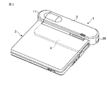
図1は、例えばメタノールを燃料とするアクティブ型のDMFC1を開示している。このDMFC1は、例えばポータブルコンピュータ2のような電子機器の電源として使用可能な大きさを有している。
FIG. 1 discloses an
DMFC1は、装置本体3と載置部4とを備えている。装置本体3は、ポータブルコンピュータ2の幅方向に沿う細長い箱状に形成されている。載置部4は、ポータブルコンピュータ2の後端部を載置し得るように、装置本体3の前端から張り出している。載置部4の上面に電源コネクタ5が配置されている。電源コネクタ5は、載置部4の上にポータブルコンピュータ2を載せた時に、このポータブルコンピュータ2に電気的に接続されるようになっている。
The DMFC 1 includes an apparatus
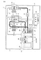
図3および図4に示すように、装置本体3は、燃料カートリッジ6、混合タンク7、DMFCスタック8、第1の凝縮器9および第2の凝縮器10を収容している。燃料カートリッジ6は、燃料供給源の一例であり、例えば燃料としての高濃度メタノールを収容している。燃料カートリッジ6は、装置本体3の長手方向に沿う一端部に取り外し可能に支持されて、交換が可能となっている。燃料カートリッジ6は、カバー11によって覆われている。カバー11は、燃料カートリッジ6の交換作業を容易に行えるように、装置本体3の一端部に取り外し可能に支持されている。
As shown in FIGS. 3 and 4, the apparatus
燃料カートリッジ6は、第1の燃料供給管12を介して混合タンク7に接続されている。第1の燃料供給管12は、高濃度メタノールを燃料カートリッジ6から混合タンク7に送り込む燃料ポンプ13を有している。混合タンク7は、高濃度メタノールを希釈して例えば濃度数%〜数十%のメタノール水溶液(希釈燃料)を生成するためのものであり、上記燃料カートリッジ6に隣接している。
The
DMFCスタック8は、メタノールの化学反応を利用して発電を行う燃料電池の一例である。DMFCスタック8は、燃料極(アノード)14と、空気極(カソード)15と、これら両極14,15の間に介在された電界質膜16とを有している。
The
DMFCスタック8の燃料極14は、第2の燃料供給管18を介して混合タンク7に接続されている。第2の燃料供給管18は燃料供給路の一例であり、燃料極14の一端に接続されている。第2の燃料供給管18は、混合タンク7内のメタノール水溶液を燃料極14に送り込む送液ポンプ19を有している。
The
燃料極14の他端は、燃料戻し管20を介して混合タンク7に接続されている。燃料戻し管20は、燃料極14から排出される未反応のメタノール水溶液や燃料極14での酸化反応により生成された二酸化炭素を混合タンク7に戻すためのものである。未反応のメタノール水溶液および二酸化炭素は、燃料極14から排出される排出物質の一つであり、燃料極14から排出された直後では、DMFCスタック8の発電動作時の熱影響を受けてメタノール水溶液の水温が60℃以上となっている。
The other end of the
上記第1の凝縮器9は、燃料戻し管20の途中に設置されている。第1の凝縮器9は、燃料極14から混合タンク7に戻るメタノール水溶液を冷却するためのものである。第1の凝縮器9は、メタノール水溶液が流れる管21と、この管21に熱的に接続された複数の放熱フィン22とを有している。
The
DMFCスタック8の空気極15は、空気供給管24を介して吸気口25に接続されている。吸気口25は、発電に供する空気を大気中から取り入れるためのものである。空気供給管24は、空気供給路の一例であり、空気極15の一端に接続されている。空気供給管24は、吸気口25から取り入れた空気を空気極15に送り込む送気ポンプ26を有している。
The
第2の凝縮器10は、排気管27を介して空気極15の他端に接続されている。第2の凝縮器10は、空気極15から排出される水蒸気や水のような排出物質を冷却するためのものであり、排気管27の下流端に接続されている。第2の凝縮器10は、回収タンク28を有している。回収タンク28は、空気極15から排出される水および水蒸気から回収された水を貯溜するためのものである。第2の凝縮器10で水分が分離された気体成分は、第2の凝縮器10から大気中に放出される。
The
回収タンク28は、回収管29を介して燃料戻し管20に接続されている。回収管29は、回収タンク28に貯えられた水を燃料戻し管20を介して混合タンク7に送り込む回収ポンプ30を有している。
The
さらに、排気管27は、空気極15と第2の凝縮器10との間で分岐された分岐管31を有している。分岐管31の上流端は混合タンク7に接続されている。分岐管31は、混合タンク7に戻された二酸化炭素を排気管27を経由して第2の凝縮器10に導くためのものである。第2の凝縮器10に導かれた二酸化炭素は、第2の凝縮器10から大気中に放出される。
Further, the
図4に示すように、第1の凝縮器9および第2の凝縮器10は、装置本体3の他端部に設置されており、燃料カートリッジ6に対しDMFCスタック8を間に挟んだ反対側に位置している。第1および第2の凝縮器9,10は、互いに間隔を存して向かい合っており、これら凝縮器9,10の間に第1のファン33および第2のファン34が配置されている。
As shown in FIG. 4, the
第1のファン33は、第1の凝縮器9と向かい合っている。第1のファン33が動作すると、第1の凝縮器9を通り抜けて第1のファン33に向うような冷却風の流れが形成され、この冷却風により第1の凝縮器9が冷却される。第1の凝縮器9を冷却した冷却風は、第1のファン33の吐出口33aから吐き出される。
The
第2のファン34は、第2の凝縮器10と向かい合っている。第2のファン34が動作すると、第2の凝縮器10を通り抜けて第2のファン34に向うような冷却風の流れが形成され、この冷却風により第2の凝縮器10が冷却される。第2の凝縮器10を冷却した冷却風は、第2のファン34の吐出口34aから吐き出される。さらに、第2の凝縮器10から排出される二酸化炭素のような不純物にしても、冷却風の流れに乗じて吐出口34aから吐き出される。
The
図1および図4に示すように、装置本体3は、その他端に排気口35を有している。排気口35は、第1および第2のファン33,34の吐出口33a,34aと向かい合っている。吐出口33a,34aから吐き出される冷却風および二酸化炭素のような不純物は、排気口35を通じて装置本体3の外に排出される。
As shown in FIGS. 1 and 4, the apparatus
図3に示すように、DMFC1は、制御部36を有している。制御部36は、例えば混合タンク7内で生成されるメタノール水溶液の濃度および液量を制御したり、ポータブルコンピュータ2との間で情報をやりとりして、ポータブルコンピュータ2に供給する電力を制御するためのものである。制御部36は、DMFC1の載置部4に収容されているとともに、電源コネクタ5およびDMFCスタック8に電気的に接続されている。
As shown in FIG. 3, the
メタノール水溶液の濃度は、燃料カートリッジ6から混合タンク7に供給される高濃度メタノールの量、DMFCスタック8の燃料極14から混合タンク7に戻される未反応のメタノール水溶液の量およびDMFCスタック8の空気極15から混合タンク7に戻される水の量を制御部36で制御することにより調節される。
The concentration of the methanol aqueous solution includes the amount of high-concentration methanol supplied from the
具体的には、混合タンク7は、タンク内のメタノール水溶液の水位を検出する水位センサ37と、メタノール水溶液の温度を検出する温度センサ38と、メタノール水溶液の濃度を検出する濃度センサ39とを備えている。各センサ37,38,39によって検出されたメタノール水溶液に関する情報は、制御部36に送られる。制御部36は、各センサ37,38,39からの情報に基づいて、例えば燃料ポンプ13や回収ポンプ30を制御する。
Specifically, the
これにより、燃料カートリッジ6から混合タンク7に流入する高濃度メタノールの量および回収タンク28から混合タンク7に流入する水の量が調節され、メタノール水溶液の濃度が発電性能を良好に維持できる値に制御される。
As a result, the amount of high-concentration methanol flowing from the
図3および図4に示すように、メタノール水溶液を生成する混合タンク7は、カプラ41を備えている。カプラ41は、混合タンク7に第1および第2の予備カートリッジ42a,42bを選択的に取り外し可能に接続するためのものであり、混合タンク7の底部に設けられている。第1および第2の予備カートリッジ42a,42bの内容量は、例えば混合タンク7の内容量の半分程度に小さく設定されている。
As shown in FIGS. 3 and 4, the
第1の予備カートリッジ42aは、混合タンク7から余分なメタノール水溶液を取り出す際に使用するものであって、この第1の予備カートリッジ42aは、最初から空となっている。これに対し、第2の予備カートリッジ42bは、混合タンク7にメタノール水溶液を補給する時に使用するものであって、この第2の予備カートリッジ42bの内部に、水又は所定の濃度に希釈されたメタノール水溶液が充填されている。
The first
カブラ41に第1の予備カートリッジ42a又は第2の予備カートリッジ42bを接続した状態では、カプラ41内の流通路(図示せず)を通じて混合タンク7の内部と第1の予備カートリッジ42a又は第2の予備カートリッジ42bの内部が互いに連通された状態となる。したがって、混合タンク7と第1の予備カートリッジ42a又は混合タンク7と第2の予備カートリッジ42bとの間においてメタノール水溶液の流通が可能となる。それとともに、第1の予備カートリッジ42a又は第2の予備カートリッジ42bは、混合タンク7と一緒に取り外し可能なカバー11で覆い隠される。
In a state where the first
さらに、カプラ41は、図示しない遮断弁を内蔵している。遮断弁は、カプラ41から第1の予備カートリッジ42a又は第2の予備カートリッジ42bを取り外した時に連通路を遮断し、メタノール水溶液の漏洩を防止する。
Furthermore, the
次に、DMFC1の発電動作について説明する。
Next, the power generation operation of the
燃料カートリッジ6に貯えられた高濃度メタノールは、燃料ポンプ13によって混合タンク7に送り込まれる。混合タンク7には、DMFCスタック8の空気極15から回収された水およびDMFCスタック8の燃料極14から排出される未反応のメタノール水溶液(低濃度メタノール)が戻される。そのため、高濃度メタノールは、混合タンク7内で水および低濃度メタノールと混じり合って希釈され、予め決められた濃度のメタノール水溶液が生成される。
The high-concentration methanol stored in the
混合タンク7で生成されたメタノール水溶液は、送液ポンプ19によってDMFCスタック8の燃料極14に送り込まれる。燃料極14では、メタノールが水と反応して酸化され、水素イオン、二酸化炭素および電子を生成する。水素イオンは、DMFCスタック8の電界質膜16を透過して空気極15に達する。
The aqueous methanol solution generated in the
燃料極14で生成された二酸化炭素は、未反応のメタノール水溶液と一緒に第1の凝縮器9に導かれ、第1のファン33から送風される冷却風により冷やされた後に、燃料戻し管20を介して混合タンク7に戻される。混合タンク7に戻された二酸化炭素は、混合タンク7内で気化するとともに、分岐管31から排気管27に流入する。
The carbon dioxide produced at the
一方、発電に供する空気は、吸気口25から取り込まれるとともに、送気ポンプ26を介して DMFCスタック8の空気極15に送り込まれる。空気極15では、空気中の酸素が水素イオン、電子と結合して還元され、水蒸気が生成される。この時、燃料極14と空気極15との間に接続された外部回路に電子が流れて発電動作が行われる。
On the other hand, air to be used for power generation is taken in from the
空気極15で生成された水蒸気は、排気管27に流れ込むとともに、この排気管27内で混合タンク7からの二酸化炭素と合流して第2の凝縮器10に導かれる。第2の凝縮器10では、第2のファン34から送風される冷却風により水蒸気が冷却されて水となる。この水は、回収タンク28に一時的に貯溜される。水分が分離され、かつ二酸化炭素のような不純物を含む気体は、第2の凝縮器10から排出されるとともに、この第2の凝縮器10を通過した冷却風と共に第2のファン34の吐出口34aから排気口35に向けて吐き出される。
The water vapor generated at the
回収タンク28に貯えられた水は、回収ポンプ30を介して混合タンク7に戻され、高濃度メタノールを希釈するための水として再利用される。
The water stored in the
このように動作するDMFC1において、回収タンク28から混合タンク7に戻る水量は、DMFC1の使用環境、湿度および発電量に応じて変化する。例えばDMFC1を多湿の環境の下で使用した場合は、回収タンク28に回収される水の量が増大するとともに、この回収タンク28から混合タンク7に戻る水量が多くなる。
In the
本実施の形態では、混合タンク7の水位を常に水位センサ37で検出し、この水位を制御部36で監視している。そのため、制御部36は、混合タンク7内の水位が予め決められた基準水位を超えた時点で、例えば音や光により混合タンク7が満水状態にあることを報知する。
In the present embodiment, the water level of the
混合タンク7が満水であるとの知らせを受けた時は、装置本体3からカバー11を取り外し、混合タンク7およびカプラ41を露出させる。次に、図5に示すように混合タンク7のカプラ41に空の第1の予備カートリッジ42aを接続する。これにより、図5に矢印Aで示すように、混合タンク7内のメタノール水溶液が重力によりカプラ41から第1の補助カートリッジ42a内に流出し、混合タンク7内のメタノール水溶液の水位が下がる。
When the notification that the
第1の予備カートリッジ42aが満水となった時は、この第1の予備カートリッジ42aをカプラ41から取り外す。取り外した第1の予備カートリッジ42aは、廃棄処分とするか、あるいは給水用として保存しておくことが望ましい。
When the first
一方、例えばDMFC1を低湿度の環境の下で使用した場合は、回収タンク28に回収される水の量が減少するとともに、この回収タンク28から混合タンク7に戻る水量が少なくなる。このため、混合タンク7内の水位が予め決められた水位を下回ると、制御部36は、例えば音や光により混合タンク7内のメタノール水溶液が少なすぎることを報知する。
On the other hand, for example, when the
混合タンク7内のメタノール水溶液が少ないとの知らせを受けた時は、装置本体3からカバー11を取り外し、混合タンク7およびカプラ41を露出させる。次に、図6に示すように混合タンク7のカプラ41にメタノール水溶液が充填された第2の予備カートリッジ42bを接続する。これにより、図6に矢印Bで示すように、第2の予備カートリッジ42b内のメタノール水溶液が重力によりカプラ41から混合タンク7内に流れ込み、混合タンク7内のメタノール水溶液の水位が上昇する。
When it is notified that the aqueous methanol solution in the
混合タンク7にメタノール水溶液を補給するに当っては、第2の予備カートリッジ42bの代わりに、例えば混合タンク7内のメタノール水溶液を排出する際に使用した後、給水用として保存してある第1の予備カートリッジ42aを用いてもよい。
When the methanol aqueous solution is supplied to the
このような本実施の形態に係るDMFC1によれば、混合タンク7が満水又は混合タンク7内のメタノール水溶液が少なすぎる場合のいずれにおいても、混合タンク7内のメタノール水溶液の水位をDMFC1の外部から容易にコントロールすることができる。
According to the
言い換えると、専用の治具を用いることなく簡単に混合タンク7の排水および混合タンク7への給水を行うことができ、混合タンク7内のメタノール水溶液の水位を適正範囲内に保持することができる。
In other words, drainage of the
このため、ユーザが必要に応じて第1および第2の補助カートリッジ42a,42bを混合タンク7に着脱することで、水過多や水不足によるDMFC1の稼働停止を回避することができる。よって、DMFC1を連続的に稼働させることができ、ポータブルコンピュータ2に安定して電力を供給できる。
For this reason, if the user attaches and detaches the first and second
さらに、上記構成によると、混合タンク7にメタノール水溶液を補給したり、混合タンク7からメタノール水溶液を排出する際に、劇物の一種であるメタノールに直接手が触れることもない。したがって、メタノール水溶液の取り扱いが容易となり、ユーザの利便性が高まる。
Furthermore, according to the above configuration, when the methanol aqueous solution is replenished to the
加えて、混合タンク7のカプラ41は、単にカバー11を装置本体3から取り外すだけでDMFC1の外部に露出する。このため、DMFC1を分解することなく混合タンク7内のメタノール水溶液を排出したり、この混合タンク7内にメタノール水溶液を補給することができ、作業性が向上するといった利点がある。
In addition, the
なお、本発明に係る燃料電池装置は、ポータブルコンピュータ用に限らず、例えば携帯形情報端末のようなその他の電子機器用の電源としても実施可能である。 The fuel cell device according to the present invention is not limited to a portable computer but can be implemented as a power source for other electronic devices such as a portable information terminal.
6…燃料カートリッジ、7…混合タンク、8…燃料電池(DMFCスタック)、14…燃料極、15…空気極、18…燃料供給路(第2の燃料供給管)、24…空気供給路(空気供給管)、42a…第1の予備カートリッジ、42b…第2の予備カートリッジ。 6 ... Fuel cartridge, 7 ... Mixing tank, 8 ... Fuel cell (DMFC stack), 14 ... Fuel electrode, 15 ... Air electrode, 18 ... Fuel supply path (second fuel supply pipe), 24 ... Air supply path (air) Supply pipe), 42a... First spare cartridge, 42b... Second spare cartridge .
Claims (4)
燃料極および空気極を有する燃料電池と、
上記燃料容器から供給される燃料と、上記燃料電池から排出される液状の排出物質とを混合することで希釈燃料を生成する混合タンクと、
上記燃料電池の上記燃料極に上記混合タンクで生成された上記希釈燃料を供給する燃料供給路と、
上記燃料電池の上記空気極に発電に供する空気を供給する空気供給路と、
上記混合タンクの底部に取り外し可能に接続され、上記混合タンクに接続した時に、上記混合タンクの内部の上記希釈燃料を上記混合タンクから取り出す第1の予備容器と、
上記第1の予備容器に代えて上記混合タンクの底部に取り外し可能に接続され、上記混合タンクに接続した時に、上記混合タンクに希釈燃料を補給する第2の予備容器と、
を具備する燃料電池装置。 A fuel container containing fuel;
A fuel cell having a fuel electrode and an air electrode;
A mixing tank that generates diluted fuel by mixing the fuel supplied from the fuel container and the liquid emission material discharged from the fuel cell;
A fuel supply passage for supplying the diluted fuel produced in the mixing tank to the fuel electrode of the fuel cell,
An air supply path for supplying air to be subjected to power generation to the air electrode of the fuel cell,
A first auxiliary container that is removably connected to the bottom of the mixing tank and that, when connected to the mixing tank, takes the diluted fuel inside the mixing tank out of the mixing tank;
A second spare container removably connected to the bottom of the mixing tank in place of the first spare container and replenishing the mixing tank with diluted fuel when connected to the mixing tank;
A fuel cell device comprising:
Priority Applications (1)
| Application Number | Priority Date | Filing Date | Title |
|---|---|---|---|
| JP2005270756A JP4886255B2 (en) | 2005-09-16 | 2005-09-16 | Fuel cell device |
Applications Claiming Priority (1)
| Application Number | Priority Date | Filing Date | Title |
|---|---|---|---|
| JP2005270756A JP4886255B2 (en) | 2005-09-16 | 2005-09-16 | Fuel cell device |
Publications (2)
| Publication Number | Publication Date |
|---|---|
| JP2007080794A JP2007080794A (en) | 2007-03-29 |
| JP4886255B2 true JP4886255B2 (en) | 2012-02-29 |
Family
ID=37940853
Family Applications (1)
| Application Number | Title | Priority Date | Filing Date |
|---|---|---|---|
| JP2005270756A Expired - Fee Related JP4886255B2 (en) | 2005-09-16 | 2005-09-16 | Fuel cell device |
Country Status (1)
| Country | Link |
|---|---|
| JP (1) | JP4886255B2 (en) |
Families Citing this family (4)
| Publication number | Priority date | Publication date | Assignee | Title |
|---|---|---|---|---|
| KR101040838B1 (en) * | 2007-10-30 | 2011-06-14 | 삼성에스디아이 주식회사 | FUEL CELL SYSTEM and FLUID-SENSING DEVICE therefor |
| JP5245567B2 (en) * | 2008-06-23 | 2013-07-24 | トヨタ自動車株式会社 | Fuel cell system |
| WO2013011609A1 (en) * | 2011-07-19 | 2013-01-24 | パナソニック株式会社 | Direct oxidation fuel cell system |
| CN102332593B (en) * | 2011-08-18 | 2014-07-16 | 上海中垚科技发展有限公司 | Totally enclosed type power supply system for mine escape capsule |
Family Cites Families (4)
| Publication number | Priority date | Publication date | Assignee | Title |
|---|---|---|---|---|
| JPH1097862A (en) * | 1996-09-24 | 1998-04-14 | Matsushita Electric Ind Co Ltd | Power supply |
| US7553571B2 (en) * | 2003-04-15 | 2009-06-30 | The Gillette Company | Management system for a fuel cell and method thereof |
| JP4437016B2 (en) * | 2003-06-18 | 2010-03-24 | パナソニック株式会社 | Fuel cell filling and collecting device, fuel cell system, and fuel cell filling and collecting device regenerator |
| JP4532924B2 (en) * | 2003-09-19 | 2010-08-25 | 富士フイルム株式会社 | Portable device |
-
2005
- 2005-09-16 JP JP2005270756A patent/JP4886255B2/en not_active Expired - Fee Related
Also Published As
| Publication number | Publication date |
|---|---|
| JP2007080794A (en) | 2007-03-29 |
Similar Documents
| Publication | Publication Date | Title |
|---|---|---|
| US7998630B2 (en) | Fuel cell | |
| JP2007005053A (en) | Fuel cell device | |
| JP2007123245A (en) | Fuel cell system | |
| JP2006252953A (en) | Fuel cell device and electronic apparatus | |
| JP4886255B2 (en) | Fuel cell device | |
| JP2007005050A (en) | Fuel cell device | |
| JP2006216495A (en) | Fuel cell unit | |
| JP5161431B2 (en) | Fuel cell device | |
| KR20100025026A (en) | Humidification device and for fuel cell system | |
| JP2009054546A (en) | Driving method of fuel cell device | |
| JP2006252955A (en) | Fuel cell device and electronic apparatus | |
| JP2007005051A (en) | Fuel cell device | |
| JP2007095591A (en) | Fuel cell system | |
| JP2007299647A (en) | Fuel cell, and control method of fuel cell | |
| JP5075360B2 (en) | Fuel cell with cooling device | |
| JP2008066201A (en) | Fuel cell | |
| JP2008117536A (en) | Fuel cell | |
| JP2007018837A (en) | Hydrogen gas dilution apparatus for fuel cell | |
| JP2008084593A (en) | Fuel cell | |
| JP2006004680A (en) | Fuel cell system and transportation vehicle using it | |
| JP2005108714A (en) | Fuel cell | |
| JP3367774B2 (en) | Solid polymer fuel cell power supply system | |
| CN114361539B (en) | Exhaust control method of tail exhaust circulation system and liquid discharge control method thereof | |
| JP2008300304A (en) | Fuel cell power generation system | |
| KR101980067B1 (en) | A liquid electrolyte fuel cell system |
Legal Events
| Date | Code | Title | Description |
|---|---|---|---|
| A621 | Written request for application examination |
Free format text: JAPANESE INTERMEDIATE CODE: A621 Effective date: 20080620 |
|
| A131 | Notification of reasons for refusal |
Free format text: JAPANESE INTERMEDIATE CODE: A131 Effective date: 20110809 |
|
| A521 | Written amendment |
Free format text: JAPANESE INTERMEDIATE CODE: A523 Effective date: 20111003 |
|
| TRDD | Decision of grant or rejection written | ||
| A01 | Written decision to grant a patent or to grant a registration (utility model) |
Free format text: JAPANESE INTERMEDIATE CODE: A01 Effective date: 20111115 |
|
| A01 | Written decision to grant a patent or to grant a registration (utility model) |
Free format text: JAPANESE INTERMEDIATE CODE: A01 |
|
| A61 | First payment of annual fees (during grant procedure) |
Free format text: JAPANESE INTERMEDIATE CODE: A61 Effective date: 20111209 |
|
| FPAY | Renewal fee payment (event date is renewal date of database) |
Free format text: PAYMENT UNTIL: 20141216 Year of fee payment: 3 |
|
| FPAY | Renewal fee payment (event date is renewal date of database) |
Free format text: PAYMENT UNTIL: 20141216 Year of fee payment: 3 |
|
| LAPS | Cancellation because of no payment of annual fees |