JP4885432B2 - Image display device, image display method, and image display program - Google Patents
Image display device, image display method, and image display program Download PDFInfo
- Publication number
- JP4885432B2 JP4885432B2 JP2004238252A JP2004238252A JP4885432B2 JP 4885432 B2 JP4885432 B2 JP 4885432B2 JP 2004238252 A JP2004238252 A JP 2004238252A JP 2004238252 A JP2004238252 A JP 2004238252A JP 4885432 B2 JP4885432 B2 JP 4885432B2
- Authority
- JP
- Japan
- Prior art keywords
- image
- display
- extracted
- images
- display area
- Prior art date
- Legal status (The legal status is an assumption and is not a legal conclusion. Google has not performed a legal analysis and makes no representation as to the accuracy of the status listed.)
- Expired - Fee Related
Links
Images


Classifications
-
- A—HUMAN NECESSITIES
- A61—MEDICAL OR VETERINARY SCIENCE; HYGIENE
- A61B—DIAGNOSIS; SURGERY; IDENTIFICATION
- A61B1/00—Instruments for performing medical examinations of the interior of cavities or tubes of the body by visual or photographical inspection, e.g. endoscopes; Illuminating arrangements therefor
- A61B1/04—Instruments for performing medical examinations of the interior of cavities or tubes of the body by visual or photographical inspection, e.g. endoscopes; Illuminating arrangements therefor combined with photographic or television appliances
- A61B1/042—Instruments for performing medical examinations of the interior of cavities or tubes of the body by visual or photographical inspection, e.g. endoscopes; Illuminating arrangements therefor combined with photographic or television appliances characterised by a proximal camera, e.g. a CCD camera
-
- A—HUMAN NECESSITIES
- A61—MEDICAL OR VETERINARY SCIENCE; HYGIENE
- A61B—DIAGNOSIS; SURGERY; IDENTIFICATION
- A61B1/00—Instruments for performing medical examinations of the interior of cavities or tubes of the body by visual or photographical inspection, e.g. endoscopes; Illuminating arrangements therefor
- A61B1/00002—Operational features of endoscopes
- A61B1/00043—Operational features of endoscopes provided with output arrangements
- A61B1/00045—Display arrangement
- A61B1/0005—Display arrangement combining images e.g. side-by-side, superimposed or tiled
-
- A—HUMAN NECESSITIES
- A61—MEDICAL OR VETERINARY SCIENCE; HYGIENE
- A61B—DIAGNOSIS; SURGERY; IDENTIFICATION
- A61B1/00—Instruments for performing medical examinations of the interior of cavities or tubes of the body by visual or photographical inspection, e.g. endoscopes; Illuminating arrangements therefor
- A61B1/04—Instruments for performing medical examinations of the interior of cavities or tubes of the body by visual or photographical inspection, e.g. endoscopes; Illuminating arrangements therefor combined with photographic or television appliances
- A61B1/041—Capsule endoscopes for imaging
-
- G—PHYSICS
- G16—INFORMATION AND COMMUNICATION TECHNOLOGY [ICT] SPECIALLY ADAPTED FOR SPECIFIC APPLICATION FIELDS
- G16H—HEALTHCARE INFORMATICS, i.e. INFORMATION AND COMMUNICATION TECHNOLOGY [ICT] SPECIALLY ADAPTED FOR THE HANDLING OR PROCESSING OF MEDICAL OR HEALTHCARE DATA
- G16H10/00—ICT specially adapted for the handling or processing of patient-related medical or healthcare data
- G16H10/60—ICT specially adapted for the handling or processing of patient-related medical or healthcare data for patient-specific data, e.g. for electronic patient records
-
- G—PHYSICS
- G16—INFORMATION AND COMMUNICATION TECHNOLOGY [ICT] SPECIALLY ADAPTED FOR SPECIFIC APPLICATION FIELDS
- G16H—HEALTHCARE INFORMATICS, i.e. INFORMATION AND COMMUNICATION TECHNOLOGY [ICT] SPECIALLY ADAPTED FOR THE HANDLING OR PROCESSING OF MEDICAL OR HEALTHCARE DATA
- G16H15/00—ICT specially adapted for medical reports, e.g. generation or transmission thereof
-
- G—PHYSICS
- G16—INFORMATION AND COMMUNICATION TECHNOLOGY [ICT] SPECIALLY ADAPTED FOR SPECIFIC APPLICATION FIELDS
- G16H—HEALTHCARE INFORMATICS, i.e. INFORMATION AND COMMUNICATION TECHNOLOGY [ICT] SPECIALLY ADAPTED FOR THE HANDLING OR PROCESSING OF MEDICAL OR HEALTHCARE DATA
- G16H30/00—ICT specially adapted for the handling or processing of medical images
- G16H30/20—ICT specially adapted for the handling or processing of medical images for handling medical images, e.g. DICOM, HL7 or PACS
-
- G—PHYSICS
- G16—INFORMATION AND COMMUNICATION TECHNOLOGY [ICT] SPECIALLY ADAPTED FOR SPECIFIC APPLICATION FIELDS
- G16H—HEALTHCARE INFORMATICS, i.e. INFORMATION AND COMMUNICATION TECHNOLOGY [ICT] SPECIALLY ADAPTED FOR THE HANDLING OR PROCESSING OF MEDICAL OR HEALTHCARE DATA
- G16H30/00—ICT specially adapted for the handling or processing of medical images
- G16H30/40—ICT specially adapted for the handling or processing of medical images for processing medical images, e.g. editing
Description
この発明は、格納された複数の画像を撮像順にしたがって順次表示する画像表示装置、画像表示方法および画像表示プログラムに関する。 The present invention relates to an image display device, an image display method, and an image display program for sequentially displaying a plurality of stored images in the order of imaging.
近年、内視鏡の分野においては、飲込み型のカプセル型内視鏡が提案されている。このカプセル型内視鏡には、撮像機能と無線通信機能とが設けられている。カプセル型内視鏡は、観察(検査)のために被検体の口から飲込まれた後、自然排出されるまでの間、体腔内、たとえば、胃、小腸などの臓器の内部をその蠕動運動にしたがって移動し、移動にともない、たとえば0.5秒間隔で被検体内画像の撮像を行う機能を有する。 In recent years, in the field of endoscopes, swallowable capsule endoscopes have been proposed. This capsule endoscope is provided with an imaging function and a wireless communication function. Capsule endoscopes are peristaltic in the body cavity, for example, inside the organs such as stomach and small intestine, after being swallowed from the subject's mouth for observation (examination) and before being spontaneously discharged. And has a function of taking images of the subject at intervals of 0.5 seconds, for example.
体腔内を移動する間、カプセル型内視鏡によって撮像された画像データは、順次無線通信により外部に送信された外部に設けられたメモリに蓄積される。無線通信機能とメモリ機能とを備えた受信機を携帯することにより、被検体は、カプセル型内視鏡を飲込んだ後、排出されるまでの間にわたって、自由に行動できる。カプセル型内視鏡が排出された後、医者もしくは看護士においては、メモリに蓄積された画像データに基づいて臓器の画像をディスプレイに表示させて診断を行うことができる(特許文献1参照)。 While moving in the body cavity, image data captured by the capsule endoscope is stored in an external memory sequentially transmitted to the outside by wireless communication. By carrying a receiver having a wireless communication function and a memory function, the subject can freely move between swallowing the capsule endoscope and discharging it. After the capsule endoscope is ejected, the doctor or nurse can make a diagnosis by displaying an organ image on a display based on the image data stored in the memory (see Patent Document 1).
ところで、近年、カプセル型内視鏡によって撮像された画像の中から、画像処理によって自動的に出血部位を含む画像を抽出する技術が提案されている。しかしながら、従来では、メモリに蓄積された画像がディスプレイに順次表示され、抽出画像が表示された場合に所定のマーキングが表示されていた。医師もしくは看護士は、抽出画像の確認のためにディスプレイに表示される画像を一枚ずつ確認する必要があったため、撮像された画像の確認時間に多くの時間を費やしていた。また、表示された抽出画像が被検体内部のどの位置で撮像されたかが分かりにくく、医師や看護士による迅速な診断ができない場合があった。 By the way, in recent years, a technique has been proposed in which an image including a bleeding site is automatically extracted by image processing from an image captured by a capsule endoscope. However, conventionally, images stored in a memory are sequentially displayed on a display, and a predetermined marking is displayed when an extracted image is displayed. The doctor or nurse had to check the images displayed on the display one by one in order to check the extracted image, and therefore spent a lot of time checking the captured image. In addition, it is difficult to know at which position in the subject the displayed extracted image is captured, and there is a case where a doctor or a nurse cannot make a quick diagnosis.
この発明は、上記した従来技術の欠点に鑑みてなされたものであり、ユーザによる迅速な画像確認を可能とする画像表示装置、画像表示方法および画像表示プログラムを提供することを目的とする。 The present invention has been made in view of the above-described drawbacks of the prior art, and an object thereof is to provide an image display device, an image display method, and an image display program that enable a user to quickly confirm an image.
上述した課題を解決し、目的を達成するために、この発明にかかる画像表示装置は、格納された複数の画像を撮像順にしたがって順次表示する表示手段を備えた画像表示装置において、前記表示手段に対して、格納された前記複数の画像から所定の抽出条件で予め抽出された抽出画像を表示させる制御手段を備えたことを特徴とする。 In order to solve the above-described problems and achieve the object, an image display device according to the present invention includes a display unit that sequentially displays a plurality of stored images according to an imaging order. On the other hand, there is provided control means for displaying an extracted image previously extracted from the stored plurality of images under a predetermined extraction condition.
また、この発明にかかる画像表示装置は、前記表示手段に表示される画像として、格納された前記複数の画像あるいは前記抽出画像のいずれかを指示する画像指示情報を入力する入力手段を備え、前記制御手段は、前記表示手段が所定の領域に表示する画像を前記画像指示情報によって指示された画像に切り替え、前記表示手段に対して該切り替えた画像を前記所定の表示領域に表示させることを特徴とする。 The image display apparatus according to the present invention further includes an input unit that inputs image instruction information indicating any of the plurality of stored images or the extracted image as an image displayed on the display unit, The control means switches the image displayed on the predetermined area by the display means to the image indicated by the image instruction information, and causes the display means to display the switched image on the predetermined display area. And
また、この発明にかかる画像表示装置は、前記制御手段は、格納された前記複数の画像から、前記所定の表示領域に表示された前記抽出画像のフレームに比して前および/または後のフレームの所定数分の画像を前後画像として抽出し、前記表示手段に対して、該前後画像を前記抽出画像の表示位置に対応させて表示させることを特徴とする。 Further, in the image display device according to the present invention, the control means includes a frame before and / or after the plurality of stored images as compared to the frame of the extracted image displayed in the predetermined display area. A predetermined number of images are extracted as front and rear images, and the front and rear images are displayed on the display unit in correspondence with display positions of the extracted images.
また、この発明にかかる画像表示装置は、前記制御手段は、前記前後画像と該前後画像に対応する前記抽出画像とをもとに静止画像ファイルを生成し、該静止画像ファイルを出力することを特徴とする。 In the image display device according to the present invention, the control unit generates a still image file based on the front and rear images and the extracted image corresponding to the front and rear images, and outputs the still image file. Features.
また、この発明にかかる画像表示装置は、前記制御手段は、前記前後画像と該前後画像に対応する前記抽出画像とをもとに動画像ファイルを生成し、該動画像ファイルを出力することを特徴とする。 In the image display device according to the present invention, the control unit generates a moving image file based on the front and rear images and the extracted image corresponding to the front and rear images, and outputs the moving image file. Features.
また、この発明にかかる画像表示装置は、格納された前記複数の画像は、被検体内部を撮像した画像であることを特徴とする。 In the image display device according to the present invention, the plurality of stored images are images obtained by imaging the inside of the subject.
また、この発明にかかる画像表示装置は、前記制御手段は、前記抽出画像および前記前後画像における前記被検体の識別情報を前記静止画像ファイルあるいは前記動画像ファイルに対応づけて出力することを特徴とする。 The image display device according to the present invention is characterized in that the control means outputs the identification information of the subject in the extracted image and the preceding and following images in association with the still image file or the moving image file. To do.
また、この発明にかかる画像表示装置は、前記所定の抽出条件は、前記被検体の異常部が撮像されていることを特徴とする。 In the image display device according to the present invention, the predetermined extraction condition is that an abnormal part of the subject is imaged.
また、この発明にかかる画像表示装置は、前記異常部は、出血部であることを特徴とする。 The image display device according to the present invention is characterized in that the abnormal part is a bleeding part.
また、この発明にかかる画像表示方法は、格納された複数の画像を撮像順にしたがって順次表示する画像表示方法において、表示される画像として、格納された前記複数の画像あるいは格納された前記複数の画像から所定の抽出条件で予め抽出された抽出画像のいずれかを指示する画像指示情報を入力する入力ステップと、表示手段の所定の表示領域に表示される画像を前記画像指示情報によって指示された画像に切り替える切り替えステップと、該切り替えた画像を前記所定の表示領域に表示する表示ステップと、を含むことを特徴とすることを特徴とする。 The image display method according to the present invention is the image display method for sequentially displaying the plurality of stored images according to the imaging order, and the plurality of stored images or the plurality of stored images as displayed images. An input step for inputting image instruction information indicating any of the extracted images previously extracted from the image under a predetermined extraction condition, and an image indicated by the image instruction information for an image displayed in a predetermined display area of the display means And a display step for displaying the switched image in the predetermined display area.
また、この発明にかかる画像表示方法は、格納された前記複数の画像から、前記所定の表示領域に表示された前記抽出画像のフレームに比して前および/または後のフレームの所定数分の画像を前後画像として抽出する抽出ステップを含み、前記表示ステップは、該前後画像を前記抽出画像の表示位置に対応させて表示することを特徴とする。 In addition, the image display method according to the present invention is based on a predetermined number of frames before and / or after the plurality of stored images as compared with the frame of the extracted image displayed in the predetermined display area. It includes an extraction step for extracting images as front and rear images, and the display step displays the front and rear images in correspondence with display positions of the extracted images.
また、この発明にかかる画像表示方法は、前記抽出ステップにおいて抽出された前記前後画像と該前後画像に対応する前記抽出画像とをもとに静止画像ファイルまたは動画像ファイルを生成し、該静止画像ファイルまたは該動画像ファイルを出力する画像ファイル出力ステップを備えたことを特徴とする。 The image display method according to the present invention generates a still image file or a moving image file based on the front and rear images extracted in the extraction step and the extracted image corresponding to the front and rear images, and the still image An image file output step for outputting the file or the moving image file is provided.
また、この発明にかかる画像表示プログラムは、格納された複数の画像を撮像順にしたがって順次表示する画像表示プログラムにおいて、表示される画像として、格納された前記複数の画像あるいは格納された前記複数の画像から所定の抽出条件で予め抽出された抽出画像のいずれかを指示する画像指示情報を入力する入力手順と、表示手段の所定の表示領域に表示される画像を前記画像指示情報によって指示された画像に切り替える切り替え手順と、該切り替えた画像を前記所定の表示領域に表示する表示手順と、を含むことを特徴とする。 Further, the image display program according to the present invention is an image display program for sequentially displaying a plurality of stored images in the order of imaging, and the plurality of stored images or the plurality of stored images as displayed images. An input procedure for inputting image instruction information indicating any one of the extracted images extracted in advance under a predetermined extraction condition from the image, and an image indicated by the image instruction information on an image displayed in a predetermined display area of the display means And a display procedure for displaying the switched image in the predetermined display area.
また、この発明にかかる画像表示プログラムは、格納された前記複数の画像から、前記所定の表示領域に表示された前記抽出画像のフレームに比して前および/または後のフレームの所定数分の画像を前後画像として抽出する抽出手順を含み、前記表示手順は、該前後画像を前記抽出画像の表示位置に対応させて表示することを特徴とする。 In addition, the image display program according to the present invention provides a predetermined number of frames before and / or after the plurality of stored images as compared with the frame of the extracted image displayed in the predetermined display area. It includes an extraction procedure for extracting an image as a front and rear image, and the display procedure displays the front and rear image in correspondence with the display position of the extracted image.
また、この発明にかかる画像表示プログラムは、前記抽出手順において抽出された前記前後画像と該前後画像に対応する前記抽出画像とをもとに静止画像ファイルまたは動画像ファイルを生成し、該静止画像ファイルまたは該動画像ファイルを出力する画像ファイル出力手順を備えたことを特徴とする。 The image display program according to the present invention generates a still image file or a moving image file based on the front and rear images extracted in the extraction procedure and the extracted image corresponding to the front and rear images, and the still image An image file output procedure for outputting a file or the moving image file is provided.
本発明によれば、格納された複数の画像の中から予め所定の抽出条件で抽出された抽出画像を表示させる制御手段を備えるため、ユーザによる迅速な抽出画像の確認を可能とするという効果を奏する。 According to the present invention, since the control means for displaying the extracted image extracted in advance from the stored plurality of images under the predetermined extraction condition is provided, it is possible to quickly confirm the extracted image by the user. Play.
以下、図面を参照して、この発明の実施の形態である画像表示装置について説明する。なお、この実施の形態によりこの発明が限定されるものではない。また、図面の記載において、同一部分には同一の符号を付している。また、本実施の形態にかかる画像表示装置として、カプセル型内視鏡を用いた被検体内情報取得システムにおける画像表示装置を例として説明する。 Hereinafter, an image display apparatus according to an embodiment of the present invention will be described with reference to the drawings. Note that the present invention is not limited to the embodiments. In the description of the drawings, the same parts are denoted by the same reference numerals. Further, as an image display apparatus according to the present embodiment, an image display apparatus in an in-vivo information acquiring system using a capsule endoscope will be described as an example.
(実施の形態1)
まず、実施の形態1にかかる画像表示装置について説明する。本実施の形態1にかかる画像表示装置は、表示画面に表示される画像を簡易に切り替え、表示画面に抽出画像または撮像画像のいずれかを表示する。
(Embodiment 1)
First, the image display apparatus according to the first embodiment will be described. The image display apparatus according to the first embodiment easily switches the image displayed on the display screen, and displays either the extracted image or the captured image on the display screen.
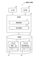
図1は、本実施の形態における被検体内情報取得システムの全体構成を示す模式図である。図1に示すように、本実施の形態における被検体内情報取得システムは、受信機能を有する受信装置2と、被検体1の体内に導入され、体腔内画像を撮像して受信装置2に対してデータ送信を行うカプセル型内視鏡3とを備える。また、被検体内情報取得システムは、受信装置2が受信したデータに基づいて体腔内画像を表示する画像表示装置4と、受信装置2と画像表示装置4との間のデータ受け渡しを行うための携帯型記録媒体5とを備える。受信装置2は、被検体1によって着用される受信ジャケット2aと、受信ジャケット2aを介して受信される無線信号の処理等を行う外部装置2bとを備える。
FIG. 1 is a schematic diagram showing an overall configuration of an in-vivo information acquiring system according to the present embodiment. As shown in FIG. 1, the in-vivo information acquiring system according to the present embodiment is introduced into a body of a receiving device 2 having a receiving function and the
画像表示装置4は、カプセル型内視鏡3によって撮像された体腔内画像を表示するためのものであり、携帯型記録媒体5によって得られるデータに基づいて画像表示を行うワークステーション等を有する。画像表示装置4は、カプセル型内視鏡3が撮像した複数の静止画像を撮像順にしたがって順次表示する。以下、この順次表示された画像を擬似動画像という。また、画像表示装置4は、所定の抽出条件をもとに画像処理によって抽出された抽出画像を表示する。
The image display device 4 is for displaying an in-vivo image captured by the
携帯型記録媒体5は、外部装置2bおよび画像表示装置4に対して着脱可能であって、両者に対する挿着時に情報の出力または記録が可能な構造を有する。具体的には、携帯型記録媒体5は、カプセル型内視鏡3が被検体1の体腔内を移動している間は外部装置2bに挿着されてカプセル型内視鏡3から送信されるデータを記録する。そして、カプセル型内視鏡3が被検体1から排出された後、つまり、被検体1の内部の撮像が終った後には、外部装置2bから取り出されて画像表示装置4に挿着され、画像表示装置4によって記録したデータが読み出される構成を有する。外部装置2bと画像表示装置4との間のデータの受け渡しをコンパクトフラッシュ(登録商標)メモリ等の携帯型記録媒体5によって行う構成以外にも、外部装置2bと画像表示装置4との間を有線接続する構成をとることも可能である。
The
ここで、図2を参照して画像表示装置4について説明する。図2は、図1に示す画像表示装置4の概略構成を示すブロック図である。図2に示すように、画像表示装置4は、入力部20、表示部30、記憶部40、制御部50を備える。
Here, the image display device 4 will be described with reference to FIG. FIG. 2 is a block diagram showing a schematic configuration of the image display device 4 shown in FIG. As shown in FIG. 2, the image display device 4 includes an
入力部20は、キーボードやマウスなどのポインティングデバイスなどによって実現され、画像表示装置4の動作指示および画像表示装置4が行なう処理の指示情報を入力し、各指示情報を制御部50に送出する。入力部20は、表示部30に表示される画像として、擬似動画像または所定の抽出条件をもとに画像処理部51によって抽出された抽出画像のいずれかを指示する画像指示情報を入力する。
The
表示部30は、CRTディスプレイ、液晶ディスプレイ等によって実現され、入力部20の指示情報あるいは指示結果などを表示する。表示部30は、制御部50の制御のもと、所定の画像表示領域に擬似動画像または抽出画像のいずれかを表示する。
The
記憶部40は、たとえばハードディスク装置などによって実現される。記憶部40には、各種画像などが保持され、特に、カプセル型内視鏡3によって撮像された画像群Paおよび制御部50の画像処理部51によって抽出された抽出画像群PbがそれぞれフォルダF1,F2内に格納される。
The
制御部50は、入力部20、表示部30、記憶部40の各処理または動作を制御する。制御部50は、画像処理部51および表示制御部52を備える。画像処理部51は、フォルダF1に格納された複数の画像の中から所定の抽出条件を有する画像を抽出する。画像処理部51は、特願2004−120367に示すように、画像の中に色度図における所定の色情報に該当する領域が所定面積以上含まれていた場合、この画像を抽出画像として抽出する。たとえば、画像処理部51は、画像の色情報のうち赤色要素の有無および分布をもとに出血部の有無を判断し、出血部があると判断した画像を抽出画像として抽出する。表示制御部52は、表示部30における画像表示処理を制御するとともに、入力部20から入力された画像指示情報をもとに、表示部30が所定の画像表示領域に表示する画像を画像指示情報において指示された擬似動画像または抽出画像のいずれかの画像に切り替え、表示部30に対して、この切り替えた画像を所定の画像表示領域に表示させる。
The
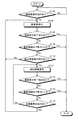
つぎに、図3を参照して、制御部50による画像表示処理手順について説明する。図3において、制御部50は、入力部20からの擬似動画像表示を指示する指示情報があったか否かを判断する(ステップS102)。制御部50は、擬似動画像表示を指示する指示情報があるまでステップS102の判断を繰り返す。制御部50が擬似動画像表示を指示する指示情報があったと判断した場合(ステップS102:Yes)、表示制御部52は、画像表示領域にフォルダF1に格納された複数の画像を撮像順にしたがって順次表示させて、擬似動画像表示を行わせる(ステップS104)。
Next, an image display processing procedure by the
表示制御部52は、入力部20からの画像表示の終了を指示する指示情報があるか否かを判断し(ステップS106)、この指示情報があった場合には(ステップS106:Yes)、表示部30における画像表示を終了する。この場合、表示部30の画像表示領域における擬似動画像表示が終了する。これに対し、表示制御部52は、入力部20からの画像表示の終了を指示する指示情報がないと判断した場合(ステップS106:No)、表示制御部52が画像群Paの最終画像まで表示したか否かを判断する(ステップS108)。表示制御部52は、画像群Paの最終画像まで表示したと判断した場合(ステップS108:Yes)、表示部30の画像表示領域における擬似動画像表示を終了する。
The
一方、表示制御部52が画像群Paの最終画像まで表示していないと判断した場合(ステップS108:No)、表示制御部52は、入力部20からの画像指示情報の有無をもとに、表示部30に対する抽出画像の表示指示があるか否かを判断する(ステップS110)。表示制御部52は、抽出画像の表示指示がないと判断した場合(ステップS110:No)、ステップS104に進み、表示部30に対して擬似動画像の表示を継続させる。
On the other hand, when the
また、表示制御部52は、抽出画像の表示指示があると判断した場合(ステップS110:Yes)、表示部30の画像表示領域に表示する画像を抽出画像に切り替え、表示部30に対して、記憶部40のフォルダF2に格納された抽出画像群Pbの抽出画像を画像表示領域に表示させる。(ステップS112)。
Further, when the
つぎに、表示制御部52は、ステップS106と同様に、入力部20からの画像表示の終了を指示する指示情報があるか否かを判断し(ステップS114)、この指示情報があった場合には(ステップS114:Yes)、表示部30における画像表示を終了する。この場合、表示部30の画像表示領域における抽出画像表示が終了する。これに対し、表示制御部52は、入力部20からの画像表示の終了を指示する指示情報がないと判断した場合(ステップS114:No)、表示部30が抽出画像群である画像群Pbの最終画像まで表示したか否かを判断する(ステップS116)。表示制御部52は、表示部30が画像群Pbの最終画像まで表示したと判断した場合(ステップS116:Yes)、表示部30の画像表示領域における抽出画像表示を終了する。
Next, as in step S106, the
一方、表示制御部52は、表示部30が画像群Pbの最終画像まで表示していないと判断した場合(ステップS116:No)、入力部20からの画像指示情報の有無をもとに、フォルダF1に格納された画像の擬似動画像の表示指示、すなわち、全画像の表示指示があるか否かを判断する(ステップS118)。表示制御部52は、全画像の表示指示がないと判断した場合(ステップS118:No)、ステップS112に進み、表示部30に対して抽出画像の表示を継続させる。
On the other hand, if the
また、表示制御部52は、全画像の表示指示があると判断した場合(ステップS118:Yes)、ステップS104に進み、表示部30の画像表示領域に表示する画像を擬似動画像に切り替え、表示部30に対して、記憶部40のフォルダF1に格納された画像群Paの画像を画像表示領域に順次表示させる擬似動画像表示を行う。
If the
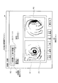
つぎに、図4および図5を参照して、表示部30の表示画面上における擬似動画像および抽出画像の切り替えについて説明する。図4および図5は、表示部30の表示画面の一例を示す図であり、表示部30の表示画面には、ウィンドウWが表示される。ウィンドウWは、大きくは、画像表示領域A1および画像指示表示領域A2を有し、画像表示領域A1の上部には画像指示表示領域A2が表示され、画像表示領域A1の下部には、再生ボタン24を含む各種動画表示制御ボタンが表示される。画像表示領域A1には、画像指示情報において指示された擬似動画像または抽出画像のいずれかが表示される。画像指示表示領域A2には、画像表示領域A1に表示される画像をそれぞれ表示したボタンが表示される。このボタンのうち、「全画像」と表示された全画像表示ボタン25は、擬似動画像の表示モードに対応し、「抽出画像」と表示された抽出画像表示ボタン26は抽出画像の表示モードに対応する。
Next, switching of the pseudo moving image and the extracted image on the display screen of the
ここで、図4を参照して、画像表示領域に表示される画像の切り替えについて説明する。たとえば、入力部20のマウスなどの動作により、図4に示すカーソル23が再生ボタン24上に移動され、マウスの左ボタンがクリックされることによって、擬似動画表示の開始を指示する指示情報が入力部20から制御部50に入力される。この結果、画像表示領域A1には、フォルダF1に格納された画像群Paのうち画像P1,P2が撮像順にしたがって擬似動画像として表示される。画像表示領域A1には、ユーザが画像指示表示領域A2上の抽出画像表示ボタン26を選択しない限り、フォルダF1に格納された画像が擬似動画像として撮像順にしたがって順次表示される。
Here, switching of images displayed in the image display area will be described with reference to FIG. For example, by the operation of the mouse or the like of the
そして、ユーザが、画像表示領域A1に表示される画像を擬似動画像から抽出画像に変更したい場合には、ユーザは、入力部20のマウスを動かし、カーソル23を画像指示表示領域A2上の抽出画像表示ボタン26上に移動させ、クリックする。このようなユーザの動作によって、入力部20は、抽出画像表示ボタン26を選択し、表示制御部52に対して画像表示領域A1に表示する画像を抽出画像に指示する画像指示情報を入力する。その後、表示制御部52は、この画像指示情報にしたがい、画像表示領域A1に表示する画像を擬似動画像である「全画像」から「抽出画像」に切り替える。そして、表示制御部52は、表示部30に対して、この切り替えた抽出画像を画像表示領域A1に表示させる。この結果、図5に示すように、画像表示領域A1には、フォルダF2に格納された画像であって、たとえば出血部32を含む抽出画像Pe11,Pe31が撮像順にしたがって表示される。画像表示領域A1には、ユーザが画像指示表示領域A2上の全画像表示ボタン25を選択しない限り、フォルダF2に格納された抽出画像が撮像順にしたがって順次表示される。
When the user wants to change the image displayed in the image display area A1 from the pseudo moving image to the extracted image, the user moves the mouse of the
さらに、ユーザが抽出画像の表示中に画像表示領域A1に表示される画像を擬似動画像に切り替える場合、マウスを動かし、カーソル23を全画像表示ボタン25上に移動させ、マウスの左ボタンをクリックする。この結果、入力部20は、画像表示領域A1に表示される画像を擬似動画像表示に切り替える画像指示情報を制御部50に入力する。表示制御部52は、この画像指示情報にしたがって、画像表示領域A1に表示される画像を抽出画像から擬似動画像に切り替え、表示部30に対して擬似動画像表示を行わせる。
Further, when the user switches the image displayed in the image display area A1 to the pseudo moving image while the extracted image is displayed, the user moves the mouse, moves the
このように、本実施の形態1にかかる画像表示装置4は、表示部30に対して、格納された複数の画像の中から予め所定の抽出条件で抽出された抽出画像を表示させるため、ユーザによる迅速な抽出画像の確認を可能にするという効果を奏する。また、本実施の形態1にかかる画像表示装置4は、表示部30の画像表示領域に表示される画像を擬似動画像または抽出画像のいずれかに簡易に切り替えることができるため、ユーザは、画像表示領域に表示される画像を自由に切り替えることができる。したがって、本実施の形態1にかかる画像表示装置4によれば、ユーザによる迅速かつ柔軟な画像確認を実現することができるという効果を奏する。
As described above, the image display apparatus 4 according to the first embodiment causes the
なお、本実施の形態1では、図5に示すように、抽出画像として出血部32を含む抽出画像Pe11,Pe31を表示する場合について説明したが、表示する抽出画像を各種抽出条件などに応じて選択できるとしてもよい。たとえば、画像処理部51は、出血部を含む出血画像、腫瘍を含む腫瘍画像、クローン病部位を含むクローン病画像、および、食道、胃、小腸などの各撮像位置に対応する画像をそれぞれ抽出するとして説明する。また、抽出画像として、各ユーザがそれぞれ選択した画像も含まれる場合もある。この場合、図6に示すように、ユーザは、擬似動画像表示から抽出画像表示に切り替える際、抽出画像ボタン26を選択する。そして、ユーザは、メニューM1に示す各抽出条件の中から表示させたい抽出条件上にカーソル23を移動させ、クリックすることによって、所望の抽出条件で抽出された抽出画像を選択することができる。この結果、画像表示領域A1には、ユーザが選択した抽出条件に応じた抽出画像が表示される。
In the first embodiment, as shown in FIG. 5, the case where the extracted images Pe11 and Pe31 including the bleeding
(実施の形態2)
つぎに、実施の形態2について説明する。実施の形態2では、抽出画像とともに該抽出画像の前のフレームまたは後のフレームの画像を表示させるため、ユーザは、表示された抽出画像が被検体内部のどの位置で撮像されたかを迅速に確認することができる。
(Embodiment 2)
Next, a second embodiment will be described. In the second embodiment, since the image of the previous or subsequent frame of the extracted image is displayed together with the extracted image, the user can quickly confirm at which position inside the subject the displayed extracted image is captured. can do.
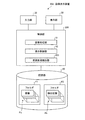
図7は、実施の形態2にかかる画像表示装置の概略構成を示すブロック図である。図7に示すように、実施の形態2にかかる画像表示装置204は、実施の形態1にかかる制御部50に比して、前後画像抽出部253をさらに備えた制御部250を有する。入力部20は、表示部30の画像表示領域に表示された抽出画像の1フレーム前または1フレーム後のいずれかの画像の表示を指示するフレーム情報を入力する。前後画像抽出部253は、入力部20から入力されたフレーム情報をもとに、記憶部40のフォルダF1に格納された画像群Paの中から、画像表示領域に表示された抽出画像の1フレーム前または1フレーム後の画像を前後画像として抽出する。表示制御部52は、表示部30に対して、所定の前後画像表示領域に前後画像抽出部253が抽出した画像を表示させる。
FIG. 7 is a block diagram of a schematic configuration of the image display apparatus according to the second embodiment. As illustrated in FIG. 7, the image display apparatus 204 according to the second embodiment includes a
つぎに、図8を参照して、画像表示装置204における制御部250による画像表示処理手順について説明する。まず、制御部250は、図3に示すステップS102〜ステップS112と同様に、擬似動画像表示指示に対する判断処理(ステップS202)、擬似動画像表示処理(ステップS204)、画像表示終了指示に対する判断処理(ステップS206)、最終画像表示に対する判断処理(ステップS208)、抽出画像表示指示に対する判断処理(ステップS210)、抽出画像表示処理(ステップS212)を行う。
Next, an image display processing procedure performed by the
その後、前後画像抽出部253は、入力部20から入力されたフレーム情報の有無をもとに、画像表示領域に表示された抽出画像の1フレーム前または1フレーム後の画像の表示指示があるか否かを判断する(ステップS214)。
Thereafter, based on the presence / absence of the frame information input from the
前後画像抽出部253が画像表示領域に表示された抽出画像の1フレーム前または1フレーム後の画像の表示指示があると判断した場合(ステップS214:Yes)、表示制御部52と前後画像抽出部253とは、画像表示領域に表示された抽出画像の1フレーム前または1フレーム後の画像を表示部30に対して表示させる前後フレーム画像表示処理を行う(ステップS216)。前後フレーム画像表示処理では、まず、前後画像抽出部253が、フォルダF1に格納された画像群Paから、フレーム情報の指示に応じて、画像表示領域に表示された抽出画像の1フレーム前または1フレーム後の画像を抽出する。その後、表示制御部52は、表示部30に対して、前後画像抽出部253が抽出した画像を所定の前後画像表示領域に表示させる。
When the front-rear
前後フレーム画像表示処理(ステップS216)後または前後画像抽出部253が画像表示領域に表示された抽出画像の1フレーム前または1フレーム後の画像の表示指示がないと判断した場合(ステップS214:No)、図3に示すステップS114〜ステップS118と同様に、画像表示終了指示に対する判断処理(ステップS218)、最終画像表示に対する判断処理(ステップS220)、擬似動画像表示である全画像表示指示に対する判断処理(ステップS222)を行う。
After the front and rear frame image display processing (step S216) or when the front and rear
つぎに、図9および図10を参照して、表示部30の表示画面上における前後画像表示について説明する。図9および図10は、表示部30の表示画面の一例を示す図である。ウィンドウWには、前後画像表示制御領域A3および前後画像を表示する前後画像表示領域A4がさらに設けられ、画像表示領域A1の下部に前後画像表示領域A4が表示され、前後画像表示領域A4の下部に前後画像表示制御領域A3が表示される。前後画像表示制御領域A3には、後フレームボタン27、前フレームボタン28の各種前後画像表示制御処理を示すボタン画像が表示される。前後画像表示領域A4には、画像表示領域A1に表示された各画像に応じた前後画像が表示される。図9では、たとえば、画像表示領域A1に抽出画像Pe11,Pe31が表示される。
Next, with reference to FIG. 9 and FIG. 10, front and rear image display on the display screen of the
まず、図9を参照して、抽出画像Pe11,Pe31の1フレーム後の画像を前後画像として表示する場合について説明する。ユーザは、カーソル23を後フレームボタン27上に移動し、マウスの左ボタンをクリックする。前後画像抽出部253は、抽出画像Pe11,Pe31の1フレーム後の画像の表示を指示するフレーム情報が入力されると、この指示にしたがって、フォルダF1に格納された画像群Paから、抽出画像Pe11の1フレーム後の画像P12と、抽出画像Pe31の1フレーム後の画像P32とを抽出する。表示制御部52は、表示部30に対して、前後画像抽出部253が抽出した画像P12,P32を抽出画像Pe11,Pe31の表示位置に対応させて前後画像表示領域A4に表示させる。したがって、図9に示すように、ウィンドウWの前後画像表示領域A4には、抽出画像Pe11の1フレーム後の画像P12と、抽出画像Pe31の1フレーム後の画像P32とが抽出画像Pe11,Pe31の表示位置に対応して前後画像表示領域A4に表示される。
First, with reference to FIG. 9, a case where an image one frame after the extracted images Pe11 and Pe31 is displayed as a front and rear image will be described. The user moves the
さらに、抽出画像の1フレーム後の画像とともに、この抽出画像の1フレーム前の画像を表示してもよい。この場合、図10に示すように、後フレームボタン27が選択された状態で、カーソル23を前フレームボタン28上に移動し、クリックする。前後画像抽出部253は、抽出画像Pe11,Pe31の1フレーム後の画像とともに抽出画像Pe11,Pe31の1フレーム前の画像の表示を指示するフレーム情報が入力されると、この指示にしたがって、フォルダF1に格納された画像群Paから、抽出画像Pe11の1フレーム前の画像P10と、抽出画像Pe31の1フレーム前の画像P30とを抽出する。表示制御部52は、表示部30に対して、前後画像抽出部253が抽出した画像P10,P30を抽出画像Pe11,Pe31の表示位置に対応させて前フレーム画像表示領域A6に表示させる。また、画像P12,P32は、後フレーム画像表示領域A5に表示される。したがって、図10に示すように、画像表示領域A1の左領域に設けられた前フレーム画像表示領域A6には、抽出画像Pe11,Pe31の1フレーム前の画像P10,P30が表示され、画像表示領域A1の右領域に設けられた後フレーム画像表示領域A5には、抽出画像Pe11,Pe31の1フレーム後の画像P12,P32が表示される。
Furthermore, the image one frame before the extracted image may be displayed together with the image one frame after the extracted image. In this case, as shown in FIG. 10, with the
このように、本実施の形態2にかかる画像表示装置204は、抽出画像とともに該抽出画像の前のフレームおよび後のフレームの画像あるいはいずれか一方のフレームの画像を表示するため、実施の形態1と同様の効果を奏するとともに、ユーザは、表示された抽出画像が被検体内部のどの位置で撮像されたかを迅速に確認することができるという効果を奏する。 As described above, the image display device 204 according to the second embodiment displays the image of the previous frame and the subsequent frame of the extracted image or the image of one of the frames together with the extracted image. In addition, the user can quickly confirm at which position in the subject the displayed extracted image was captured.
(実施の形態3)
つぎに、実施の形態3について説明する。実施の形態3では、抽出画像とともに該抽出画像よりも前のフレームまたは後のフレームの所定数の画像を順次表示または動画形式で表示することによって、ユーザによる抽出画像の被検体内部における位置確認をさらに迅速化することができる。
(Embodiment 3)
Next, a third embodiment will be described. In the third embodiment, the user can confirm the position of the extracted image in the subject by sequentially displaying a predetermined number of images in the frame before or after the extracted image together with the extracted image in a moving image format. Further speeding up can be achieved.
図11は、実施の形態3にかかる画像表示装置の概略構成を示すブロック図である。図11に示すように、本実施の形態3にかかる画像表示装置304は、実施の形態2にかかる制御部250に比して、画像ファイル生成部354をさらに備えた制御部350を有する。入力部20は、所定の画像表示領域に表示された抽出画像と、この抽出画像のフレームに比して前および/または後のフレームの所定数分の画像とをもとに静止画像ファイルまたは動画像ファイルの生成、出力を指示する出力指示情報を制御部350に入力する。画像ファイル生成部354は、入力部20からの出力指示情報をもとに、所定の画像表示領域に表示された抽出画像のフレームに比して前および/または後のフレームの所定数分の画像を前後画像としてフォルダF1の画像群Paから抽出し、抽出画像と抽出した前後画像をもとに静止画像ファイルまたは動画像ファイルを生成する。画像ファイル生成部354は、動画像ファイルを生成する場合、抽出画像と前後画像とを動画変換用の画像処理方法を用いて、たとえばAVI形式の動画像ファイルに変換する。そして、画像ファイル生成部354は、生成した画像ファイルを記憶部40に出力し、記憶部40のフォルダF3に記憶させる。表示制御部52は、画像ファイル生成部354が生成した静止画像ファイルまたは動画像ファイルをもとに、所定の前後画像表示領域に前後画像と抽出画像とを順次表示または動画形式で表示する。
FIG. 11 is a block diagram of a schematic configuration of the image display apparatus according to the third embodiment. As illustrated in FIG. 11, the image display device 304 according to the third embodiment includes a
つぎに、図12を参照して、制御部350による画像表示処理手順について説明する。図12において、制御部350は、図3に示すステップS102〜ステップS112と同様に、擬似動画像表示指示に対する判断処理(ステップS302)、擬似動画像表示処理(ステップS304)、画像表示終了指示に対する判断処理(ステップS306)、最終画像表示に対する判断処理(ステップS308)、抽出画像表示指示に対する判断処理(ステップS310)、抽出画像表示処理(ステップS312)を行う。その後、画像ファイル生成部354は、入力部20から入力された出力指示情報の有無をもとに、画像ファイルの出力指示があるか否かを判断する(ステップS314)。
Next, an image display processing procedure by the
画像ファイル生成部354は、画像ファイル出力指示があると判断した場合(ステップS314:Yes)、画像ファイル生成部354と表示制御部52とは、所定の画像表示領域に表示された抽出画像と、この抽出画像のフレームに比して前のフレームおよび/または後のフレームの所定数の画像とを含む画像ファイルを生成し、これらの画像ファイルをもとに前後画像表示領域に画像を表示する画像ファイル出力処理を行う(ステップS316)。
When the image
画像ファイル出力処理(ステップS316)後または画像ファイル出力指示がないと判断した場合(ステップS314:No)、図3に示すステップS114〜ステップS118と同様に、画像表示終了指示に対する判断処理(ステップS318)、最終画像表示に対する判断処理(ステップS320)、擬似動画像表示である全画像表示指示に対する判断処理(ステップS322)を行う。 After the image file output process (step S316) or when it is determined that there is no image file output instruction (step S314: No), the determination process for the image display end instruction (step S318) is performed as in steps S114 to S118 shown in FIG. ), A determination process for the final image display (step S320), and a determination process for the all-image display instruction which is a pseudo moving image display (step S322).
つぎに、図13を参照して、図12に示す画像ファイル出力処理の処理手順について説明する。図13において、まず、画像ファイル生成部354は、入力部20からの出力指示情報を受信する(ステップS342)。画像ファイル生成部354は、この出力指示情報にしたがって、フォルダF1に格納された抽出画像を抽出し、抽出画像の読み出しを行う(ステップS344)。この場合、画像ファイル生成部354が読み出す抽出画像は、画像表示領域に表示された抽出画像である。つぎに、画像ファイル生成部354は、出力指示情報にしたがって、読み出しを行った抽出画像のフレームに比して前および/または後のフレームの所定数分の画像を前後画像としてフォルダF1から抽出し、前後画像の読み出しを行う(ステップS346)。そして、画像ファイル生成部354は、読み出しを行った抽出画像および前後画像における被検体の識別情報である検査情報を読み出す(ステップS348)。たとえば、検査情報は、被検体である患者の氏名、識別番号、性別、生年月日である。
Next, the processing procedure of the image file output process shown in FIG. 12 will be described with reference to FIG. In FIG. 13, first, the image
その後、画像ファイル生成部354は、読み出した抽出画像と前後画像とをもとに静止画像ファイルまたは動画像ファイルを生成する画像ファイル生成処理を行う(ステップS350)。画像ファイル生成部354および表示制御部52は、生成した画像ファイルを出力する画像ファイル出力処理を行う(ステップS352)。この画像ファイル出力処理では、画像ファイル生成部354は、生成した画像ファイルをフォルダF3に出力する。また、表示制御部52は、画像ファイル生成部354が静止画像ファイルを生成した場合には、この静止画像ファイルをもとに所定の前後画像表示領域に前後画像と抽出画像とを順次表示する。一方、表示制御部52は、画像ファイル生成部354が動画像ファイルを生成した場合には、この動画像ファイルをもとに所定の前後画像表示領域に動画を表示する。なお、画像ファイル生成部354は、出力指示情報において画像ファイルと検査情報とを対応づけて出力する指示があった場合には、生成した画像ファイルに読み出した検査情報を対応づけてフォルダF3に出力する。
Thereafter, the image
つぎに、制御部350は、出力指示情報において指示された画像ファイルを全て出力したか否かを判断し(ステップS354)、画像ファイルを全て出力していないと判断した場合には(ステップS354:No)、ステップS344に進み、出力指示情報において指示された画像ファイルの生成を行い、画像ファイルを全て生成したと判断した場合には(ステップS354:Yes)、画像ファイル出力処理を終了する。
Next, the
つぎに、図14を参照して、具体的な操作および処理について説明する。図14は、表示部30の表示画面の一例を示す図である。図14に示すように、ウィンドウWには、ファイル出力ボタン29が設けられ、このファイル出力ボタン29をマウスの左クリックによって選択すると、ファイル出力ウィンドウMが新たに表示出力される。ファイル出力ウィンドウMには、フレーム数の記入項目Ma、「前後フレーム」の選択項目Mb、「検査情報」の選択項目Mc、「動画出力」の選択項目Mdが示されている。
Next, specific operations and processes will be described with reference to FIG. FIG. 14 is a diagram illustrating an example of the display screen of the
記入項目Maに記入されたフレーム数は、画像ファイル生成部354がフォルダF1から抽出する画像枚数に対応し、「前後フレーム」の選択項目Mbは、画像ファイル生成部354がフォルダF1から抽出画像の前後のフレームの画像を抽出するか否かを選択する項目である。記入項目Maに「10」フレームが記入され、「前後フレーム」の選択項目Mbが選択された場合、画像ファイル生成部354は、画像表示領域に表示された抽出画像と、この抽出画像の1フレーム前から10フレーム前の画像と、この抽出画像の1フレーム後から10フレーム後の画像とを抽出する。なお、「前後フレーム」の選択項目Mbが選択されない場合には、デフォルトとして、画像ファイル生成部354は、画像表示領域に表示された抽出画像とともに、この抽出画像の1フレーム前から10フレーム前あるいは1フレーム後から10フレーム後のいずれかの画像を抽出する設定としてもよい。また、「検査情報」の選択項目Mcは、画像ファイル生成部354が生成した画像ファイルに検査情報を対応づけて出力するか否かを選択する項目である。「動画出力」の選択項目Mdは、画像ファイル生成部354が生成するファイル形式を動画形式にするか否かを選択する項目である。ユーザは、カーソル23を各項目上に移動させ、キーボードからの数値入力およびマウスのクリックを行うことによって各項目の選択等を行い、出力される画像ファイルの形式を指示する。入力部20は、ユーザによって指示された内容の出力指示情報を制御部350に入力する。
The number of frames entered in the entry Ma corresponds to the number of images extracted from the folder F1 by the image
たとえば、図14に示すように、フレーム数の記入項目Maに「10フレーム」を書き込み、「前後フレーム」の選択項目Mbの選択および「動画出力」の選択項目Mdの選択後、出力ボタンMeを選択した場合について説明する。この場合、前後画像表示領域A4には、抽出画像Pelに対応する動画Pslおよび抽出画像Perに対応する動画Psrがそれぞれ表示される。動画Pslは、抽出画像Pelの前後10フレームに対応する画像20枚と抽出画像Pe1に対応する画像をもとに生成された動画像ファイルを用いて表示されたものであり、動画Psrは、抽出画像Perの前後10フレームに対応する画像20枚と抽出画像Perに対応する画像をもとに生成された動画像ファイルを用いて表示されたものである。なお、「動画出力」の選択項目Mdが選択されない場合には、前後画像表示領域A4には、抽出画像Pelの前後10フレームに対応する画像20枚および抽出画像Pelが撮像順にしたがって順次表示され、抽出画像Perの前後10フレームに対応する画像20枚および抽出画像Perが撮像順にしたがって順次表示される。 For example, as shown in FIG. 14, “10 frames” is written in the entry Ma of the number of frames, and after selecting the selection item Mb of “previous frame” and the selection item Md of “video output”, the output button Me is set. The case where it selects is demonstrated. In this case, a moving image Psl corresponding to the extracted image Pel and a moving image Psr corresponding to the extracted image Per are displayed in the front and rear image display area A4. The moving image Psl is displayed using a moving image file generated based on 20 images corresponding to 10 frames before and after the extracted image Pel and an image corresponding to the extracted image Pe1, and the moving image Psr is extracted. It is displayed using 20 images corresponding to 10 frames before and after the image Per and a moving image file generated based on an image corresponding to the extracted image Per. In addition, when the selection item Md of “moving image output” is not selected, 20 images corresponding to 10 frames before and after the extracted image Pel and the extracted image Pel are sequentially displayed in the front and rear image display area A4 according to the imaging order. Twenty images corresponding to the 10 frames before and after the extracted image Per and the extracted image Per are sequentially displayed in the order of imaging.
このように、本実施の形態3では、実施の形態1,2と同様の効果を奏するとともに、抽出画像とともに該抽出画像よりも前および/または後のフレームの所定数分の画像を順次に表示または動画で表示することによって、ユーザによる抽出画像の被検体内部における位置確認をさらに迅速化することができるという効果を奏する。 As described above, the third embodiment has the same effects as those of the first and second embodiments, and sequentially displays a predetermined number of images before and / or after the extracted image together with the extracted image. Alternatively, by displaying the moving image, it is possible to further speed up the confirmation of the position of the extracted image inside the subject by the user.
なお、本実施の形態1〜3では、図4〜図6、図9、図10および図14において、画像表示領域A1に2枚の画像を表示した場合について説明したが、もちろん、画像表示領域A1に1枚の画像を表示してもよく、4枚の画像を表示してもよく、表示枚数に制限はない。また、画像表示領域A1に表示する画像の枚数は、入力部20の指示情報をもとに変更することができるとしてもよい。
In the first to third embodiments, the case where two images are displayed in the image display area A1 in FIGS. 4 to 6, 9, 10, and 14 is described. One image may be displayed on A1, or four images may be displayed, and the number of displayed images is not limited. Further, the number of images displayed in the image display area A1 may be changed based on the instruction information of the
また、本実施の形態1〜3では、図2、図7および図11において抽出画像群Pbを格納したフォルダF2を図示したが、フォルダF1に格納された画像群Paの画像のうち所定の抽出条件を有する画像に対して抽出画像である旨を示すフラグを付与し、抽出画像を管理してもよい。 In the first to third embodiments, the folder F2 storing the extracted image group Pb is illustrated in FIGS. 2, 7, and 11, but a predetermined extraction is performed among the images of the image group Pa stored in the folder F1. A flag indicating that the image is an extracted image may be assigned to the image having the condition to manage the extracted image.
また、上記実施の形態1〜3で説明した画像表示装置4,204,304は、あらかじめ用意されたプログラムをパーソナル・コンピュータやワークステーションなどのコンピュータシステムで実行することによって実現することができる。以下、上記実施の形態で説明した画像表示装置と同様の機能を有する画像表示プログラムを実行するコンピュータシステムについて説明する。 The image display apparatuses 4, 204, and 304 described in the first to third embodiments can be realized by executing a program prepared in advance on a computer system such as a personal computer or a workstation. Hereinafter, a computer system that executes an image display program having the same function as that of the image display apparatus described in the above embodiment will be described.
図15は、上述した実施の形態を用いたコンピュータシステムの構成を示すシステム構成図であり、図16は、このコンピュータシステムにおける本体部の構成を示すブロック図である。図15に示すように、本実施の形態1〜3にかかるコンピュータシステム100は、本体部101と、本体部101からの指示によって表示画面102aに画像などの情報を表示するためのディスプレイ102と、このコンピュータシステム100に種々の情報を入力するためのキーボード103と、ディスプレイ102の表示画面102a上の任意の位置を指定するためのマウス104とを備える。
FIG. 15 is a system configuration diagram illustrating a configuration of a computer system using the above-described embodiment, and FIG. 16 is a block diagram illustrating a configuration of a main body in the computer system. As shown in FIG. 15, the
また、このコンピュータシステム100における本体部101は、図16に示すように、CPU121と、RAM122と、ROM123と、ハードディスクドライブ(HDD)124と、CD−ROM109を受け入れるCD−ROMドライブ125と、フレキシブルディスク(FD)108を受け入れるFDドライブ126と、ディスプレイ102、キーボード103並びにマウス104を接続するI/Oインターフェース127と、ローカルエリアネットワークまたは広域エリアネットワーク(LAN/WAN)106に接続するLANインターフェース128とを備える。
As shown in FIG. 16, the
さらに、このコンピュータシステム100には、インターネットなどの公衆回線107に接続するためのモデム105が接続されるとともに、LANインターフェース128およびLAN/WAN106を介して、他のコンピュータシステム(PC)111、サーバ112、プリンタ113などが接続される。
Further, a
そして、このコンピュータシステム100は、所定の記録媒体に記録された画像表示プログラムを読み出して実行することで画像表示装置を実現する。ここで、所定の記録媒体とは、フレキシブルディスク(FD)108、CD−ROM109、MOディスク、DVDディスク、光磁気ディスク、ICカードなどの「可搬用の物理媒体」の他に、コンピュータシステム100の内外に備えられるハードディスクドライブ(HDD)124や、RAM122、ROM123などの「固定用の物理媒体」、さらに、モデム105を介して接続される公衆回線107や、他のコンピュータシステム111並びにサーバ112が接続されるLAN/WAN106などのように、プログラムの送信に際して短期にプログラムを保持する「通信媒体」など、コンピュータシステム100によって読み取り可能な画像表示プログラムを記録する、あらゆる記録媒体を含むものである。
And this
すなわち、画像表示プログラムは、上記した「可搬用の物理媒体」、「固定用の物理媒体」、「通信媒体」などの記録媒体に、コンピュータ読み取り可能に記録されるものであり、コンピュータシステム100は、このような記録媒体から画像表示プログラムを読み出して実行することで画像表示装置および画像表示方法を実現する。なお、画像表示プログラムは、コンピュータシステム100によって実行されることに限定されるものではなく、他のコンピュータシステム111またはサーバ112が画像表示プログラムを実行する場合や、これらが協働して画像表示プログラムを実行するような場合にも、本発明を同様に適用することができる。
That is, the image display program is recorded on a recording medium such as the above-mentioned “portable physical medium”, “fixed physical medium”, “communication medium”, etc. so that it can be read by a computer. The image display program and the image display method are realized by reading and executing the image display program from such a recording medium. Note that the image display program is not limited to be executed by the
1 被検体
2 受信装置
2a 受信ジャケット
2b 外部装置
4,204,304 画像表示装置
5 携帯型記録媒体
20 入力部
30 表示部
40 記憶部
50,250,350 制御部
51 画像処理部
52 表示制御部
23 カーソル
24 再生ボタン
25 全画像表示ボタン
26 抽出画像表示ボタン
27 後フレームボタン
28 前フレームボタン
29 ファイル出力ボタン
253 前後画像抽出部
354 画像ファイル生成部
100 コンピュータシステム
101 本体部
102 ディスプレイ
102a 表示画面
103 キーボード
104 マウス
105 モデム
106 ローカルエリアネットワークまたは広域エリアネットワーク(LAN/WAN)
107 公衆回線
108 フレキシブルディスク(FD)
109 CD−ROM
111 他のコンピュータシステム(PC)
112 サーバ
113 プリンタ
121 CPU
122 RAM
123 ROM
124 ハードディスクドライブ(HDD)
125 CD−ROMドライブ
126 FDドライブ
127 I/Oインターフェース
128 LANインターフェース
DESCRIPTION OF
107
109 CD-ROM
111 Other computer systems (PC)
112
122 RAM
123 ROM
124 hard disk drive (HDD)
125 CD-
Claims (12)
前記表示手段に対して、格納された前記複数の画像から所定の抽出条件で予め抽出された抽出画像を前記表示手段の中央に位置する第1の表示領域に表示させる制御手段を備え、
前記制御手段は、格納された前記複数の画像から、前記第1の表示領域に表示された前記抽出画像のフレームに比して前および後の連続するフレームの所定数分の画像を前後画像として抽出し、前記表示手段に対して、前記抽出画像を表示しているときに、前記前後画像を前記第1の表示領域とは別領域である所定の第2の表示領域に表示させ、
前記第2の表示領域は、前記第1の表示領域の左側および右側にそれぞれ位置する2つの領域からなり、該2つの領域の各々は前記第1の表示領域よりも小さい領域であり、
前記第2の表示領域のうち、前記第1の表示領域の左側に位置する領域には、前記抽出画像のフレームに比して前の連続するフレームの所定数分の画像が表示され、前記第1の表示領域の右側に位置する領域には、前記抽出画像のフレームに比して後の連続するフレームの所定数分の画像が表示されることを特徴とする画像表示装置。 In an image display device comprising display means for sequentially displaying a plurality of images captured and stored continuously in a subject according to the order of imaging,
Control means for causing the display means to display, in a first display area located in the center of the display means, an extracted image pre-extracted from the stored plurality of images under a predetermined extraction condition,
The control means uses, as the front and rear images, images corresponding to a predetermined number of consecutive frames before and after the extracted image displayed in the first display area from the plurality of stored images. When extracting and displaying the extracted image on the display means, the front and rear images are displayed in a predetermined second display area that is different from the first display area ,
The second display area is composed of two areas respectively located on the left side and the right side of the first display area, and each of the two areas is an area smaller than the first display area,
Of the second display area, an area on the left side of the first display area displays a predetermined number of images of the previous consecutive frames as compared to the frame of the extracted image, and the region on the right side of the first display area, the image display device image of a predetermined number of consecutive frames after than the frame of the extracted image is characterized Rukoto appears.
前記制御手段は、前記表示手段が前記第1の表示領域に表示する画像を前記画像指示情報によって指示された画像に切り替え、前記表示手段に対して前記切り替えた画像を前記第1の表示領域に表示させることを特徴とする請求項1に記載の画像表示装置。 As an image displayed on the display means, an input means for inputting image instruction information for instructing one of the plurality of stored images or the extracted image is provided.
The control means switches the image in which the display means displays on the first display area on the image designated by the image designation information, the image switching the relative said display means to the first display region The image display apparatus according to claim 1, wherein the image display apparatus is displayed.
表示される画像として、前記複数の画像あるいは前記複数の画像から所定の抽出条件で予め抽出された抽出画像のいずれかを指示する画像指示情報を入力する入力ステップと、
前記入力ステップにおける前記画像指示情報によって指示された画像を前記記憶部から読み出し、表示手段の中央に位置する第1の表示領域に表示される画像を読み出した画像に切り替える切り替えステップと、
前記切り替えた画像を前記第1の表示領域に表示する表示ステップと、
前記入力ステップにおいて前記表示される画像として抽出画像が指示された場合、格納された前記複数の画像から、前記第1の表示領域に表示される前記抽出画像のフレームに比して前および後の連続するフレームの所定数分の画像を前後画像として抽出する抽出ステップと、
を含み、
前記表示ステップは、前記抽出画像を前記第1の表示領域に表示するとともに、前記抽出画像を表示するときに、前記抽出ステップにおいて抽出された前記前後画像を前記第1の表示領域とは別領域である所定の第2の表示領域に表示し、
前記第2の表示領域は、前記第1の表示領域の左側および右側にそれぞれ位置する2つの領域からなり、該2つの領域の各々は前記第1の表示領域よりも小さい領域であり、
前記第2の表示領域のうち、前記第1の表示領域の左側に位置する領域には、前記抽出画像のフレームに比して前の連続するフレームの所定数分の画像が表示され、前記第1の表示領域の右側に位置する領域には、前記抽出画像のフレームに比して後の連続するフレームの所定数分の画像が表示されることを特徴とする画像表示方法。 In an image display method in which an image display device having a storage unit that continuously captures images of a subject and stores a plurality of images sequentially displays the plurality of images according to an imaging order.
An input step for inputting image instruction information indicating either the plurality of images or an extracted image extracted in advance from the plurality of images under a predetermined extraction condition as an image to be displayed;
A switching step of reading an image instructed by the image instruction information in the input step from the storage unit and switching an image displayed in a first display area located in the center of the display means to the read image;
A display step of displaying the switched image in the first display area;
When an extracted image is designated as the image to be displayed in the input step, before and after the plurality of stored images compared to the frame of the extracted image displayed in the first display area An extraction step of extracting a predetermined number of images of consecutive frames as front and back images;
Including
In the display step, the extracted image is displayed in the first display area, and when the extracted image is displayed, the front and rear images extracted in the extraction step are different from the first display area. Is displayed in a predetermined second display area ,
The second display area is composed of two areas respectively located on the left side and the right side of the first display area, and each of the two areas is an area smaller than the first display area,
Of the second display area, an area on the left side of the first display area displays a predetermined number of images of the previous consecutive frames as compared to the frame of the extracted image, and the region on the right side of the first display area, an image display method which an image of a predetermined number of consecutive frames after than the frame of the extracted image is characterized Rukoto appears.
前記表示ステップは、前記生成ステップにおいて生成された前記静止画像ファイルまたは前記動画像ファイルを前記第2の表示領域に表示することを特徴とする請求項9に記載の画像表示方法。 And further including a generation step of generating a still image file or a moving image file based on the front and rear images extracted in the extraction step and the extracted image corresponding to the front and rear images,
Wherein the display step, the image display method according to claim 9, wherein the displaying the still image file or the moving image file generated in said generation step to the second display region.
表示させる画像として、前記複数の画像あるいは前記複数の画像から所定の抽出条件で予め抽出された抽出画像のいずれかを指示する画像指示情報を入力する入力手順と、
前記入力手順における前記画像指示情報によって指示された画像を前記記憶部から読み出し、表示手段の中央に位置する第1の表示領域に表示させる画像を読み出した画像に切り替える切り替え手順と、
前記切り替えた画像を前記第1の表示領域に表示させる表示手順と、
前記入力手順において前記表示させる画像として抽出画像が指示された場合、前記第1の表示領域に表示させる前記抽出画像のフレームに比して前および後の連続するフレームの所定数分の画像を前記記憶部から読み出して前後画像として抽出する抽出手順と、
を含み、
前記表示手順は、前記抽出画像を前記第1の表示領域に表示させるとともに、前記抽出画像を表示させるときに、前記抽出手順において抽出された前記前後画像を前記第1の表示領域とは別領域である所定の第2の表示領域に表示させ、
前記第2の表示領域は、前記第1の表示領域の左側および右側にそれぞれ位置する2つの領域からなり、該2つの領域の各々は前記第1の表示領域よりも小さい領域であり、
前記第2の表示領域のうち、前記第1の表示領域の左側に位置する領域には、前記抽出画像のフレームに比して前の連続するフレームの所定数分の画像が表示され、前記第1の表示領域の右側に位置する領域には、前記抽出画像のフレームに比して後の連続するフレームの所定数分の画像が表示されることを特徴とする画像表示プログラム。 In an image display program for sequentially displaying the plurality of images in accordance with the imaging order on an image display device having a storage unit that continuously captures images of the subject and stores a plurality of images.
As an image to be displayed, an input procedure for inputting image instruction information indicating either the plurality of images or an extracted image extracted in advance from the plurality of images under a predetermined extraction condition;
A switching procedure for reading an image instructed by the image instruction information in the input procedure from the storage unit and switching an image to be displayed in a first display area located in the center of the display means to the read image;
A display procedure for displaying the switched image in the first display area;
When an extracted image is designated as the image to be displayed in the input procedure, images corresponding to a predetermined number of consecutive frames before and after the extracted image to be displayed in the first display area An extraction procedure for reading out from the storage unit and extracting it as an image before and after
Including
In the display procedure, the extracted image is displayed in the first display area, and when the extracted image is displayed, the front and rear images extracted in the extraction procedure are different from the first display area. Is displayed in a predetermined second display area ,
The second display area is composed of two areas respectively located on the left side and the right side of the first display area, and each of the two areas is an area smaller than the first display area,
Of the second display area, an area on the left side of the first display area displays a predetermined number of images of the previous consecutive frames as compared to the frame of the extracted image, and the region on the right side of the first display area, the image display program image of a predetermined number of consecutive frames after than the frame of the extracted image is characterized Rukoto appears.
前記表示手順は、前記生成手順において生成された前記静止画像ファイルまたは前記動画像ファイルを前記第2の表示領域に表示させることを特徴とする請求項11に記載の画像表示プログラム。 A generation procedure for generating a still image file or a moving image file on the basis of the front and rear images extracted in the extraction procedure and the extracted image corresponding to the front and rear images;
The image display program according to claim 11, wherein the display procedure displays the still image file or the moving image file generated in the generation procedure in the second display area.
Priority Applications (5)
| Application Number | Priority Date | Filing Date | Title |
|---|---|---|---|
| JP2004238252A JP4885432B2 (en) | 2004-08-18 | 2004-08-18 | Image display device, image display method, and image display program |
| US11/660,607 US20090135249A1 (en) | 2004-08-18 | 2005-08-17 | Image display apparatus, image display method, and image display program |
| EP05780421.3A EP1787574B1 (en) | 2004-08-18 | 2005-08-17 | Image display device, image display method, and image display program |
| CN2005800283226A CN101005795B (en) | 2004-08-18 | 2005-08-17 | Image display device, image display method |
| PCT/JP2005/015022 WO2006019120A1 (en) | 2004-08-18 | 2005-08-17 | Image display device, image display method, and image display program |
Applications Claiming Priority (1)
| Application Number | Priority Date | Filing Date | Title |
|---|---|---|---|
| JP2004238252A JP4885432B2 (en) | 2004-08-18 | 2004-08-18 | Image display device, image display method, and image display program |
Publications (3)
| Publication Number | Publication Date |
|---|---|
| JP2006055262A JP2006055262A (en) | 2006-03-02 |
| JP2006055262A5 JP2006055262A5 (en) | 2007-08-23 |
| JP4885432B2 true JP4885432B2 (en) | 2012-02-29 |
Family
ID=35907503
Family Applications (1)
| Application Number | Title | Priority Date | Filing Date |
|---|---|---|---|
| JP2004238252A Expired - Fee Related JP4885432B2 (en) | 2004-08-18 | 2004-08-18 | Image display device, image display method, and image display program |
Country Status (5)
| Country | Link |
|---|---|
| US (1) | US20090135249A1 (en) |
| EP (1) | EP1787574B1 (en) |
| JP (1) | JP4885432B2 (en) |
| CN (1) | CN101005795B (en) |
| WO (1) | WO2006019120A1 (en) |
Families Citing this family (19)
| Publication number | Priority date | Publication date | Assignee | Title |
|---|---|---|---|---|
| JP2007075163A (en) * | 2005-09-09 | 2007-03-29 | Olympus Medical Systems Corp | Image display device |
| US20080232702A1 (en) * | 2005-06-27 | 2008-09-25 | Seiichiro Kimoto | Image display apparatus |
| JP5005981B2 (en) * | 2006-08-03 | 2012-08-22 | オリンパスメディカルシステムズ株式会社 | Image display device |
| US8900124B2 (en) * | 2006-08-03 | 2014-12-02 | Olympus Medical Systems Corp. | Image display device |
| JP2008301968A (en) * | 2007-06-06 | 2008-12-18 | Olympus Medical Systems Corp | Endoscopic image processing apparatus |
| JP2009050321A (en) * | 2007-08-23 | 2009-03-12 | Olympus Corp | Image processor |
| JP5215105B2 (en) * | 2008-09-30 | 2013-06-19 | オリンパスメディカルシステムズ株式会社 | Image display device, image display method, and image display program |
| CN101721199B (en) * | 2008-10-14 | 2012-08-22 | 奥林巴斯医疗株式会社 | Image display device and image display method |
| US20110032259A1 (en) * | 2009-06-09 | 2011-02-10 | Intromedic Co., Ltd. | Method of displaying images obtained from an in-vivo imaging device and apparatus using same |
| JP5636247B2 (en) * | 2010-10-06 | 2014-12-03 | Hoya株式会社 | Electronic endoscope processor and electronic endoscope apparatus |
| JP5601970B2 (en) * | 2010-10-26 | 2014-10-08 | Hoya株式会社 | Electronic endoscope processor and electronic endoscope apparatus |
| EP2687146A4 (en) * | 2011-05-30 | 2014-11-05 | Olympus Medical Systems Corp | Medical information recording device |
| JP5911294B2 (en) * | 2011-12-22 | 2016-04-27 | 株式会社東芝 | Medical image processing system |
| US9118818B2 (en) * | 2012-06-26 | 2015-08-25 | Olympus Corporation | Endoscope apparatus, reproducing apparatus, displaying method and inspection report generating apparatus |
| JP2014050514A (en) * | 2012-09-06 | 2014-03-20 | Fujifilm Corp | Electronic endoscope apparatus, captured image display control method, and captured image display control program |
| CN104424295B (en) * | 2013-09-02 | 2019-09-24 | 联想(北京)有限公司 | A kind of information processing method and electronic equipment |
| WO2019008942A1 (en) | 2017-07-03 | 2019-01-10 | 富士フイルム株式会社 | Medical image processing device, endoscope device, diagnostic support device, medical service support device and report generation support device |
| US11529038B2 (en) * | 2018-10-02 | 2022-12-20 | Elements Endoscopy, Inc. | Endoscope with inertial measurement units and / or haptic input controls |
| CN112274115A (en) * | 2020-07-03 | 2021-01-29 | 母宗军 | Integrated gastric environment detection platform and method |
Family Cites Families (30)
| Publication number | Priority date | Publication date | Assignee | Title |
|---|---|---|---|---|
| JPS5969047A (en) * | 1982-10-15 | 1984-04-19 | オリンパス光学工業株式会社 | Through-endoscope information filing system |
| US4920413A (en) * | 1989-02-28 | 1990-04-24 | Olympus Optical Co., Ltd. | Blood-vessel endoscope system for storing a frozen picture in synchronization with heart pulsation |
| JPH04357927A (en) * | 1991-01-14 | 1992-12-10 | Olympus Optical Co Ltd | Endoscope image display device |
| JPH0556918A (en) * | 1991-09-05 | 1993-03-09 | Olympus Optical Co Ltd | Endoscope device |
| JPH10118032A (en) * | 1996-10-24 | 1998-05-12 | Olympus Optical Co Ltd | Image displaying apparatus for medical treatment and method therefor |
| WO1998058593A2 (en) * | 1997-06-23 | 1998-12-30 | Koninklijke Philips Electronics N.V. | Image guided surgery system |
| JPH1175150A (en) * | 1997-08-29 | 1999-03-16 | Hitachi Denshi Ltd | Dynamic image editing method, device therefor and recording medium recorded with program for executing dynamic image editing operation |
| JP3996712B2 (en) * | 1998-11-18 | 2007-10-24 | オリンパス株式会社 | Medical image playback device |
| US6734880B2 (en) * | 1999-11-24 | 2004-05-11 | Stentor, Inc. | User interface for a medical informatics systems |
| US6709387B1 (en) * | 2000-05-15 | 2004-03-23 | Given Imaging Ltd. | System and method for controlling in vivo camera capture and display rate |
| JP2001359039A (en) * | 2000-06-09 | 2001-12-26 | Olympus Optical Co Ltd | Image recorder |
| JP2002032068A (en) * | 2000-07-18 | 2002-01-31 | Olympus Optical Co Ltd | Image processing apparatus |
| JP3601439B2 (en) * | 2000-10-31 | 2004-12-15 | セイコーエプソン株式会社 | Image display device |
| IL157892A0 (en) * | 2001-03-14 | 2004-03-28 | Given Imaging Ltd | Method and system for detecting colorimetric abnormalities |
| US7119814B2 (en) * | 2001-05-18 | 2006-10-10 | Given Imaging Ltd. | System and method for annotation on a moving image |
| US6951536B2 (en) * | 2001-07-30 | 2005-10-04 | Olympus Corporation | Capsule-type medical device and medical system |
| JP4794765B2 (en) * | 2001-07-30 | 2011-10-19 | オリンパス株式会社 | Capsule endoscope |
| JP2003093326A (en) * | 2001-09-25 | 2003-04-02 | Pentax Corp | Flexible electronic endoscope device |
| US7549129B2 (en) * | 2001-10-31 | 2009-06-16 | Microsoft Corporation | Computer system with enhanced user interface for images |
| DE60315953T2 (en) * | 2002-02-12 | 2008-05-21 | Given Imaging Ltd. | SYSTEM AND METHOD FOR DISPLAYING A PICTURE FLOW |
| US7474327B2 (en) * | 2002-02-12 | 2009-01-06 | Given Imaging Ltd. | System and method for displaying an image stream |
| US7433546B2 (en) * | 2004-10-25 | 2008-10-07 | Apple Inc. | Image scaling arrangement |
| JP2004041709A (en) * | 2002-05-16 | 2004-02-12 | Olympus Corp | Capsule medical care device |
| US7309867B2 (en) * | 2003-04-18 | 2007-12-18 | Medispectra, Inc. | Methods and apparatus for characterization of tissue samples |
| JP4583704B2 (en) * | 2002-11-01 | 2010-11-17 | オリンパス株式会社 | Endoscopic imaging device |
| JP3810381B2 (en) * | 2003-04-25 | 2006-08-16 | オリンパス株式会社 | Image display device, image display method, and image display program |
| JP5030588B2 (en) * | 2003-08-21 | 2012-09-19 | コーニンクレッカ フィリップス エレクトロニクス エヌ ヴィ | Apparatus and method for combining two images |
| US7319781B2 (en) * | 2003-10-06 | 2008-01-15 | Carestream Health, Inc. | Method and system for multiple passes diagnostic alignment for in vivo images |
| US20050075537A1 (en) * | 2003-10-06 | 2005-04-07 | Eastman Kodak Company | Method and system for real-time automatic abnormality detection for in vivo images |
| US20050196023A1 (en) * | 2004-03-01 | 2005-09-08 | Eastman Kodak Company | Method for real-time remote diagnosis of in vivo images |
-
2004
- 2004-08-18 JP JP2004238252A patent/JP4885432B2/en not_active Expired - Fee Related
-
2005
- 2005-08-17 WO PCT/JP2005/015022 patent/WO2006019120A1/en active Application Filing
- 2005-08-17 EP EP05780421.3A patent/EP1787574B1/en not_active Expired - Fee Related
- 2005-08-17 CN CN2005800283226A patent/CN101005795B/en not_active Expired - Fee Related
- 2005-08-17 US US11/660,607 patent/US20090135249A1/en not_active Abandoned
Also Published As
| Publication number | Publication date |
|---|---|
| CN101005795A (en) | 2007-07-25 |
| EP1787574A4 (en) | 2009-06-17 |
| EP1787574B1 (en) | 2016-03-23 |
| US20090135249A1 (en) | 2009-05-28 |
| EP1787574A1 (en) | 2007-05-23 |
| JP2006055262A (en) | 2006-03-02 |
| WO2006019120A1 (en) | 2006-02-23 |
| CN101005795B (en) | 2010-12-08 |
Similar Documents
| Publication | Publication Date | Title |
|---|---|---|
| JP4885432B2 (en) | Image display device, image display method, and image display program | |
| JP4594835B2 (en) | Image display device | |
| JP4575124B2 (en) | Image display device | |
| US8194096B2 (en) | Image display apparatus | |
| JP4823659B2 (en) | In vivo image display device | |
| US20080184168A1 (en) | Image display apparatus | |
| JP2007075163A (en) | Image display device | |
| JP4891646B2 (en) | Image display device | |
| JP2007075156A (en) | Image display device | |
| JP4574983B2 (en) | Image display apparatus, image display method, and image display program | |
| JP4477451B2 (en) | Image display device, image display method, and image display program | |
| JP2007058334A (en) | Filing device and filling system | |
| JP4445742B2 (en) | Image display apparatus, image display method, and image display program | |
| JP4663698B2 (en) | Image display device, image display method, and image display program | |
| JP4804739B2 (en) | Image display device, image display method, and image display program | |
| JP4598458B2 (en) | Image display device, image display method, and image display program | |
| JP4590444B2 (en) | Image display device, image display method, and image display program | |
| JP4699014B2 (en) | Image display device, image display method, and image display program | |
| JP2006345929A (en) | Image display device | |
| JP4542392B2 (en) | Image display device, image display method, and image display program | |
| JP2006061628A (en) | Data generating device, data browse system, data generation method, and data generating program | |
| JP2006075301A (en) | Image processing device, method and program | |
| JP2006060611A (en) | Image display apparatus, image display method and image display program |
Legal Events
| Date | Code | Title | Description |
|---|---|---|---|
| A521 | Request for written amendment filed |
Free format text: JAPANESE INTERMEDIATE CODE: A523 Effective date: 20070706 |
|
| A621 | Written request for application examination |
Free format text: JAPANESE INTERMEDIATE CODE: A621 Effective date: 20070706 |
|
| A131 | Notification of reasons for refusal |
Free format text: JAPANESE INTERMEDIATE CODE: A131 Effective date: 20100216 |
|
| A521 | Request for written amendment filed |
Free format text: JAPANESE INTERMEDIATE CODE: A523 Effective date: 20100416 |
|
| A131 | Notification of reasons for refusal |
Free format text: JAPANESE INTERMEDIATE CODE: A131 Effective date: 20100622 |
|
| A131 | Notification of reasons for refusal |
Free format text: JAPANESE INTERMEDIATE CODE: A131 Effective date: 20101012 |
|
| A521 | Request for written amendment filed |
Free format text: JAPANESE INTERMEDIATE CODE: A523 Effective date: 20101207 |
|
| A131 | Notification of reasons for refusal |
Free format text: JAPANESE INTERMEDIATE CODE: A131 Effective date: 20110222 |
|
| A521 | Request for written amendment filed |
Free format text: JAPANESE INTERMEDIATE CODE: A523 Effective date: 20110421 |
|
| A02 | Decision of refusal |
Free format text: JAPANESE INTERMEDIATE CODE: A02 Effective date: 20110705 |
|
| A521 | Request for written amendment filed |
Free format text: JAPANESE INTERMEDIATE CODE: A523 Effective date: 20111004 |
|
| A911 | Transfer to examiner for re-examination before appeal (zenchi) |
Free format text: JAPANESE INTERMEDIATE CODE: A911 Effective date: 20111007 |
|
| TRDD | Decision of grant or rejection written | ||
| A01 | Written decision to grant a patent or to grant a registration (utility model) |
Free format text: JAPANESE INTERMEDIATE CODE: A01 Effective date: 20111129 |
|
| A01 | Written decision to grant a patent or to grant a registration (utility model) |
Free format text: JAPANESE INTERMEDIATE CODE: A01 |
|
| A61 | First payment of annual fees (during grant procedure) |
Free format text: JAPANESE INTERMEDIATE CODE: A61 Effective date: 20111208 |
|
| FPAY | Renewal fee payment (event date is renewal date of database) |
Free format text: PAYMENT UNTIL: 20141216 Year of fee payment: 3 |
|
| R151 | Written notification of patent or utility model registration |
Ref document number: 4885432 Country of ref document: JP Free format text: JAPANESE INTERMEDIATE CODE: R151 |
|
| FPAY | Renewal fee payment (event date is renewal date of database) |
Free format text: PAYMENT UNTIL: 20141216 Year of fee payment: 3 |
|
| S531 | Written request for registration of change of domicile |
Free format text: JAPANESE INTERMEDIATE CODE: R313531 |
|
| R350 | Written notification of registration of transfer |
Free format text: JAPANESE INTERMEDIATE CODE: R350 |
|
| R250 | Receipt of annual fees |
Free format text: JAPANESE INTERMEDIATE CODE: R250 |
|
| R250 | Receipt of annual fees |
Free format text: JAPANESE INTERMEDIATE CODE: R250 |
|
| R250 | Receipt of annual fees |
Free format text: JAPANESE INTERMEDIATE CODE: R250 |
|
| R250 | Receipt of annual fees |
Free format text: JAPANESE INTERMEDIATE CODE: R250 |
|
| LAPS | Cancellation because of no payment of annual fees |