JP4885395B2 - Sheet material with composite image floating - Google Patents
Sheet material with composite image floating Download PDFInfo
- Publication number
- JP4885395B2 JP4885395B2 JP2001562245A JP2001562245A JP4885395B2 JP 4885395 B2 JP4885395 B2 JP 4885395B2 JP 2001562245 A JP2001562245 A JP 2001562245A JP 2001562245 A JP2001562245 A JP 2001562245A JP 4885395 B2 JP4885395 B2 JP 4885395B2
- Authority
- JP
- Japan
- Prior art keywords
- sheet material
- image
- light
- microlens
- composite image
- Prior art date
- Legal status (The legal status is an assumption and is not a legal conclusion. Google has not performed a legal analysis and makes no representation as to the accuracy of the status listed.)
- Expired - Lifetime
Links
- 239000000463 material Substances 0.000 title claims description 351
- 239000002131 composite material Substances 0.000 title claims description 123
- 238000007667 floating Methods 0.000 title description 25
- 230000005855 radiation Effects 0.000 claims description 9
- 239000010409 thin film Substances 0.000 claims description 7
- 239000010410 layer Substances 0.000 description 103
- 230000003287 optical effect Effects 0.000 description 50
- 238000003384 imaging method Methods 0.000 description 37
- 239000004005 microsphere Substances 0.000 description 34
- 229910052782 aluminium Inorganic materials 0.000 description 23
- XAGFODPZIPBFFR-UHFFFAOYSA-N aluminium Chemical compound [Al] XAGFODPZIPBFFR-UHFFFAOYSA-N 0.000 description 23
- VYPSYNLAJGMNEJ-UHFFFAOYSA-N Silicium dioxide Chemical compound O=[Si]=O VYPSYNLAJGMNEJ-UHFFFAOYSA-N 0.000 description 21
- 239000011651 chromium Substances 0.000 description 15
- 238000000034 method Methods 0.000 description 15
- VYZAMTAEIAYCRO-UHFFFAOYSA-N Chromium Chemical compound [Cr] VYZAMTAEIAYCRO-UHFFFAOYSA-N 0.000 description 12
- 239000010408 film Substances 0.000 description 12
- 230000008859 change Effects 0.000 description 10
- 239000000377 silicon dioxide Substances 0.000 description 10
- 235000012239 silicon dioxide Nutrition 0.000 description 10
- 238000005286 illumination Methods 0.000 description 9
- 229910052804 chromium Inorganic materials 0.000 description 8
- 239000006185 dispersion Substances 0.000 description 8
- 229910052751 metal Inorganic materials 0.000 description 8
- 239000002184 metal Substances 0.000 description 8
- 238000010586 diagram Methods 0.000 description 7
- 239000005083 Zinc sulfide Substances 0.000 description 6
- 239000011324 bead Substances 0.000 description 6
- 230000015572 biosynthetic process Effects 0.000 description 6
- 239000000919 ceramic Substances 0.000 description 6
- 238000000576 coating method Methods 0.000 description 6
- 239000000758 substrate Substances 0.000 description 6
- 229910052984 zinc sulfide Inorganic materials 0.000 description 6
- RYGMFSIKBFXOCR-UHFFFAOYSA-N Copper Chemical compound [Cu] RYGMFSIKBFXOCR-UHFFFAOYSA-N 0.000 description 5
- 239000011230 binding agent Substances 0.000 description 5
- 239000011248 coating agent Substances 0.000 description 5
- 229910052802 copper Inorganic materials 0.000 description 5
- 239000010949 copper Substances 0.000 description 5
- 230000000694 effects Effects 0.000 description 5
- 230000033001 locomotion Effects 0.000 description 5
- 229920000642 polymer Polymers 0.000 description 5
- 239000011701 zinc Substances 0.000 description 5
- KAKZBPTYRLMSJV-UHFFFAOYSA-N Butadiene Chemical compound C=CC=C KAKZBPTYRLMSJV-UHFFFAOYSA-N 0.000 description 4
- XEEYBQQBJWHFJM-UHFFFAOYSA-N Iron Chemical compound [Fe] XEEYBQQBJWHFJM-UHFFFAOYSA-N 0.000 description 4
- 229910045601 alloy Inorganic materials 0.000 description 4
- 239000000956 alloy Substances 0.000 description 4
- 229910019655 synthetic inorganic crystalline material Inorganic materials 0.000 description 4
- 238000001429 visible spectrum Methods 0.000 description 4
- 241000893640 Carcharhinus longimanus Species 0.000 description 3
- 238000002679 ablation Methods 0.000 description 3
- 238000010521 absorption reaction Methods 0.000 description 3
- 229940090961 chromium dioxide Drugs 0.000 description 3
- AYTAKQFHWFYBMA-UHFFFAOYSA-N chromium(IV) oxide Inorganic materials O=[Cr]=O AYTAKQFHWFYBMA-UHFFFAOYSA-N 0.000 description 3
- 150000001875 compounds Chemical class 0.000 description 3
- 239000011521 glass Substances 0.000 description 3
- 229910001635 magnesium fluoride Inorganic materials 0.000 description 3
- 150000002739 metals Chemical class 0.000 description 3
- 238000012986 modification Methods 0.000 description 3
- 230000004048 modification Effects 0.000 description 3
- 238000000879 optical micrograph Methods 0.000 description 3
- 239000004065 semiconductor Substances 0.000 description 3
- 239000002356 single layer Substances 0.000 description 3
- 125000006850 spacer group Chemical group 0.000 description 3
- 238000001228 spectrum Methods 0.000 description 3
- 239000003981 vehicle Substances 0.000 description 3
- DRDVZXDWVBGGMH-UHFFFAOYSA-N zinc;sulfide Chemical compound [S-2].[Zn+2] DRDVZXDWVBGGMH-UHFFFAOYSA-N 0.000 description 3
- 239000011165 3D composite Substances 0.000 description 2
- ATJFFYVFTNAWJD-UHFFFAOYSA-N Tin Chemical compound [Sn] ATJFFYVFTNAWJD-UHFFFAOYSA-N 0.000 description 2
- HCHKCACWOHOZIP-UHFFFAOYSA-N Zinc Chemical compound [Zn] HCHKCACWOHOZIP-UHFFFAOYSA-N 0.000 description 2
- XLOMVQKBTHCTTD-UHFFFAOYSA-N Zinc monoxide Chemical compound [Zn]=O XLOMVQKBTHCTTD-UHFFFAOYSA-N 0.000 description 2
- 239000003086 colorant Substances 0.000 description 2
- 229940116318 copper carbonate Drugs 0.000 description 2
- GEZOTWYUIKXWOA-UHFFFAOYSA-L copper;carbonate Chemical compound [Cu+2].[O-]C([O-])=O GEZOTWYUIKXWOA-UHFFFAOYSA-L 0.000 description 2
- 229910001610 cryolite Inorganic materials 0.000 description 2
- 239000005337 ground glass Substances 0.000 description 2
- 230000003993 interaction Effects 0.000 description 2
- 239000002648 laminated material Substances 0.000 description 2
- ORUIBWPALBXDOA-UHFFFAOYSA-L magnesium fluoride Chemical compound [F-].[F-].[Mg+2] ORUIBWPALBXDOA-UHFFFAOYSA-L 0.000 description 2
- 229910001092 metal group alloy Inorganic materials 0.000 description 2
- 239000000203 mixture Substances 0.000 description 2
- 238000006116 polymerization reaction Methods 0.000 description 2
- 238000012545 processing Methods 0.000 description 2
- 230000001681 protective effect Effects 0.000 description 2
- 238000001454 recorded image Methods 0.000 description 2
- 229910052594 sapphire Inorganic materials 0.000 description 2
- 239000010980 sapphire Substances 0.000 description 2
- 229910052709 silver Inorganic materials 0.000 description 2
- 239000004332 silver Substances 0.000 description 2
- UMGDCJDMYOKAJW-UHFFFAOYSA-N thiourea Chemical compound NC(N)=S UMGDCJDMYOKAJW-UHFFFAOYSA-N 0.000 description 2
- 239000011135 tin Substances 0.000 description 2
- 229910052718 tin Inorganic materials 0.000 description 2
- 239000010936 titanium Substances 0.000 description 2
- 238000007738 vacuum evaporation Methods 0.000 description 2
- 230000000007 visual effect Effects 0.000 description 2
- 229910052725 zinc Inorganic materials 0.000 description 2
- PFNQVRZLDWYSCW-UHFFFAOYSA-N (fluoren-9-ylideneamino) n-naphthalen-1-ylcarbamate Chemical compound C12=CC=CC=C2C2=CC=CC=C2C1=NOC(=O)NC1=CC=CC2=CC=CC=C12 PFNQVRZLDWYSCW-UHFFFAOYSA-N 0.000 description 1
- 229910052582 BN Inorganic materials 0.000 description 1
- ZOXJGFHDIHLPTG-UHFFFAOYSA-N Boron Chemical compound [B] ZOXJGFHDIHLPTG-UHFFFAOYSA-N 0.000 description 1
- PZNSFCLAULLKQX-UHFFFAOYSA-N Boron nitride Chemical compound N#B PZNSFCLAULLKQX-UHFFFAOYSA-N 0.000 description 1
- 229910052779 Neodymium Inorganic materials 0.000 description 1
- XUIMIQQOPSSXEZ-UHFFFAOYSA-N Silicon Chemical compound [Si] XUIMIQQOPSSXEZ-UHFFFAOYSA-N 0.000 description 1
- BQCADISMDOOEFD-UHFFFAOYSA-N Silver Chemical compound [Ag] BQCADISMDOOEFD-UHFFFAOYSA-N 0.000 description 1
- QAOWNCQODCNURD-UHFFFAOYSA-L Sulfate Chemical compound [O-]S([O-])(=O)=O QAOWNCQODCNURD-UHFFFAOYSA-L 0.000 description 1
- NINIDFKCEFEMDL-UHFFFAOYSA-N Sulfur Chemical compound [S] NINIDFKCEFEMDL-UHFFFAOYSA-N 0.000 description 1
- RTAQQCXQSZGOHL-UHFFFAOYSA-N Titanium Chemical compound [Ti] RTAQQCXQSZGOHL-UHFFFAOYSA-N 0.000 description 1
- XSQUKJJJFZCRTK-UHFFFAOYSA-N Urea Natural products NC(N)=O XSQUKJJJFZCRTK-UHFFFAOYSA-N 0.000 description 1
- 230000002745 absorbent Effects 0.000 description 1
- 239000002250 absorbent Substances 0.000 description 1
- 230000032900 absorption of visible light Effects 0.000 description 1
- 238000009825 accumulation Methods 0.000 description 1
- 239000000853 adhesive Substances 0.000 description 1
- 230000001070 adhesive effect Effects 0.000 description 1
- JNDMLEXHDPKVFC-UHFFFAOYSA-N aluminum;oxygen(2-);yttrium(3+) Chemical compound [O-2].[O-2].[O-2].[Al+3].[Y+3] JNDMLEXHDPKVFC-UHFFFAOYSA-N 0.000 description 1
- 239000006117 anti-reflective coating Substances 0.000 description 1
- 238000003491 array Methods 0.000 description 1
- 235000013361 beverage Nutrition 0.000 description 1
- 229910052797 bismuth Inorganic materials 0.000 description 1
- JCXGWMGPZLAOME-UHFFFAOYSA-N bismuth atom Chemical compound [Bi] JCXGWMGPZLAOME-UHFFFAOYSA-N 0.000 description 1
- 230000000903 blocking effect Effects 0.000 description 1
- 229910052810 boron oxide Inorganic materials 0.000 description 1
- 239000006229 carbon black Substances 0.000 description 1
- 229910021563 chromium fluoride Inorganic materials 0.000 description 1
- 238000012790 confirmation Methods 0.000 description 1
- 238000010276 construction Methods 0.000 description 1
- 239000002872 contrast media Substances 0.000 description 1
- XTVVROIMIGLXTD-UHFFFAOYSA-N copper(II) nitrate Chemical compound [Cu+2].[O-][N+]([O-])=O.[O-][N+]([O-])=O XTVVROIMIGLXTD-UHFFFAOYSA-N 0.000 description 1
- 239000013078 crystal Substances 0.000 description 1
- 239000012769 display material Substances 0.000 description 1
- 238000004049 embossing Methods 0.000 description 1
- 238000005530 etching Methods 0.000 description 1
- 239000004744 fabric Substances 0.000 description 1
- 238000010304 firing Methods 0.000 description 1
- PCHJSUWPFVWCPO-UHFFFAOYSA-N gold Chemical compound [Au] PCHJSUWPFVWCPO-UHFFFAOYSA-N 0.000 description 1
- 229910052737 gold Inorganic materials 0.000 description 1
- 239000010931 gold Substances 0.000 description 1
- 238000010438 heat treatment Methods 0.000 description 1
- AMGQUBHHOARCQH-UHFFFAOYSA-N indium;oxotin Chemical compound [In].[Sn]=O AMGQUBHHOARCQH-UHFFFAOYSA-N 0.000 description 1
- -1 inorganics Substances 0.000 description 1
- 150000002500 ions Chemical class 0.000 description 1
- 229910052742 iron Inorganic materials 0.000 description 1
- UQSXHKLRYXJYBZ-UHFFFAOYSA-N iron oxide Inorganic materials [Fe]=O UQSXHKLRYXJYBZ-UHFFFAOYSA-N 0.000 description 1
- 230000001788 irregular Effects 0.000 description 1
- 238000003475 lamination Methods 0.000 description 1
- HIQSCMNRKRMPJT-UHFFFAOYSA-J lithium;yttrium(3+);tetrafluoride Chemical compound [Li+].[F-].[F-].[F-].[F-].[Y+3] HIQSCMNRKRMPJT-UHFFFAOYSA-J 0.000 description 1
- 238000004519 manufacturing process Methods 0.000 description 1
- 239000007769 metal material Substances 0.000 description 1
- 229910044991 metal oxide Inorganic materials 0.000 description 1
- 150000004706 metal oxides Chemical class 0.000 description 1
- QEFYFXOXNSNQGX-UHFFFAOYSA-N neodymium atom Chemical compound [Nd] QEFYFXOXNSNQGX-UHFFFAOYSA-N 0.000 description 1
- 229910001392 phosphorus oxide Inorganic materials 0.000 description 1
- LFGREXWGYUGZLY-UHFFFAOYSA-N phosphoryl Chemical class [P]=O LFGREXWGYUGZLY-UHFFFAOYSA-N 0.000 description 1
- 239000002861 polymer material Substances 0.000 description 1
- 238000007639 printing Methods 0.000 description 1
- 230000008569 process Effects 0.000 description 1
- 230000004224 protection Effects 0.000 description 1
- 230000009467 reduction Effects 0.000 description 1
- 238000009877 rendering Methods 0.000 description 1
- 230000010076 replication Effects 0.000 description 1
- 230000004044 response Effects 0.000 description 1
- 229910052710 silicon Inorganic materials 0.000 description 1
- 239000010703 silicon Substances 0.000 description 1
- 239000007787 solid Substances 0.000 description 1
- 230000003595 spectral effect Effects 0.000 description 1
- 150000003457 sulfones Chemical class 0.000 description 1
- 150000003462 sulfoxides Chemical class 0.000 description 1
- 229910052717 sulfur Inorganic materials 0.000 description 1
- 239000011593 sulfur Substances 0.000 description 1
- 229910052715 tantalum Inorganic materials 0.000 description 1
- GUVRBAGPIYLISA-UHFFFAOYSA-N tantalum atom Chemical compound [Ta] GUVRBAGPIYLISA-UHFFFAOYSA-N 0.000 description 1
- 238000012360 testing method Methods 0.000 description 1
- 150000003568 thioethers Chemical class 0.000 description 1
- 150000003573 thiols Chemical class 0.000 description 1
- 229910052719 titanium Inorganic materials 0.000 description 1
- 238000013519 translation Methods 0.000 description 1
- 229910052720 vanadium Inorganic materials 0.000 description 1
- GPPXJZIENCGNKB-UHFFFAOYSA-N vanadium Chemical compound [V]#[V] GPPXJZIENCGNKB-UHFFFAOYSA-N 0.000 description 1
- 238000012795 verification Methods 0.000 description 1
- 229910019901 yttrium aluminum garnet Inorganic materials 0.000 description 1
- 239000011787 zinc oxide Substances 0.000 description 1
Images


Classifications
-
- G—PHYSICS
- G02—OPTICS
- G02B—OPTICAL ELEMENTS, SYSTEMS OR APPARATUS
- G02B30/00—Optical systems or apparatus for producing three-dimensional [3D] effects, e.g. stereoscopic images
- G02B30/50—Optical systems or apparatus for producing three-dimensional [3D] effects, e.g. stereoscopic images the image being built up from image elements distributed over a 3D volume, e.g. voxels
- G02B30/56—Optical systems or apparatus for producing three-dimensional [3D] effects, e.g. stereoscopic images the image being built up from image elements distributed over a 3D volume, e.g. voxels by projecting aerial or floating images
-
- G—PHYSICS
- G02—OPTICS
- G02B—OPTICAL ELEMENTS, SYSTEMS OR APPARATUS
- G02B5/00—Optical elements other than lenses
- G02B5/12—Reflex reflectors
- G02B5/126—Reflex reflectors including curved refracting surface
- G02B5/128—Reflex reflectors including curved refracting surface transparent spheres being embedded in matrix
Landscapes
- Physics & Mathematics (AREA)
- General Physics & Mathematics (AREA)
- Optics & Photonics (AREA)
- Credit Cards Or The Like (AREA)
- Laminated Bodies (AREA)
- Optical Elements Other Than Lenses (AREA)
- Stereoscopic And Panoramic Photography (AREA)
Description
【0001】
発明の分野
本発明は、観察者がシート材料に対して空間に浮かんでいると感じ、合成画像の遠近が見る角度により変化する1以上の合成画像を提供するシート材料に関する。
【0002】
発明の背景
グラフィック画像または他の指標を有するシート材料は、特に論文または文献を認証するための標識として幅広く用いられてきた。例えば、米国特許第3,154,872号、第3,801,183号、第4,082,426号、および第4,099,838号に記載されているようなシート材料は、車両ナンバープレート用確認ステッカーとして、および運転免許証、公文書、カセットテープ、トランプおよび飲料用容器のための防護フィルムとして用いられてきた。他の用途には、広告宣伝用表示およびブランド高揚に供するための独特の標識でのパトカー、消防自動車または他の緊急用車両上などの識別目的用のグラフィック用途が挙げられる。
【0003】
画像化シート材料の別の形態は、米国特許第4,200,875号(ガラノス)に開示されている。ガラノスは、画像が中でマスクまたはパターンを通してシート材料のレーザー照射により形成される、特に「レンズ露出型の高利得な再帰反射シート材料」の使用を開示している。そのシート材料は、複数の微小球のそれぞれの埋め込み表面上に被覆された金属反射層を持ち、部分的に結合剤層中に埋められ、部分的に結合剤上に露出された複数の透明ガラス微小球を含む。結合剤層は、画像化されている間にシート材料に侵入するあらゆるストレイ・ライトを最小化すると言われるカーボンブラックを含有する。レーザー光のエネルギーは、結合剤層中に埋め込まれたマイクロレンズの収束効果により、さらに集中化される。
【0004】
ガラノスの再帰反射シート材料中に形成される画像は、レーザー照射がシート材料に向けられたのと同じ角度からシート材料を見る場合に、その場合のみに、見ることができる。それは、換言すれば、画像は極めて限定された観察角度でのみ見ることができることを意味する。そういうおよび他の理由により、こうしたシート材料のある種の特性を改善しようとする願望があり続けている。
【0005】
早くも1908年にガブリエルリップマン(Gabriel Lippman)は、1以上の感光性層を有するレンズ媒体中に、一つの情景の真の3次元画像を生成するための方法を発明した。積分撮影術として知られるその方法は、De Motebello,「Processing and Display of Three−Dimensional Data II」in Proceedings of SPIE,San Diego,1984にも記載されている。リップマンの方法において、写真乾板はレンズ(または「小型レンズ」)のアレーを通して露光され、その結果、アレーの各小型レンズは、その小型レンズにより占拠されたシートの視点から見られるように再生しようとする情景のミニチュア画像を写真乾板に伝達する。写真乾板が現像された後、小型レンズアレーを通しての乾板上の合成画像を見ている観察者は撮影された情景の3次元表示を見ることになる。画像は、用いられる感光性材料に応じて、黒および白またはカラーであることが可能である。
【0006】
乾板の露光の間に小型レンズにより形成される画像は各ミニチュア画像の単一反転のみを受けるので、得られる3次元表示は偽影鏡性である。すなわち、画像の感知深さは反転されるので、対象は「裏返し」に見える。これは、画像を直すために2回の光学反転を行うことが必要になるので、大きな不利である。これらの方法は、同じ対象物の複数の光景を記録するために、単一カメラ、または多くのカメラ、または多レンズカメラによる多露光を含んで複雑であり、単一3次元画像を提供するために多画像の極めて正確な登録を必要とする。さらに、従来のカメラに依存するあらゆる方法は、カメラの前での実際の対象物の存在を必要とする。これは、さらに、仮想対象物(実質的には存在するがしかし現実には存在しない対象物を意味する)の3次元画像を生成するために悪く選択された方法を提供する。積分撮影術のさらなる不利益には、見ることが可能である実際の画像を形成するために合成画像は見る側から光を当てねばならないことがある。
【0007】
発明の概要
本発明はシート材料の上または下に浮かんで現れる合成画像を有するマイクロレンズシート材料を提供する。これらの浮かんだ画像は便宜上浮遊画像と呼ばれ、それらはシート材料の上または下に位置することができる(2次元または3次元画像のいずれかとして)か、またはシート材料の上、平面中、または下に現れる3次元画像であることができる。画像は黒および白またはカラーであり得て、観察者と共に動くように出現することができる。いくつかのホログラフィックシート材料とは違って、本発明の画像化シート材料はそれ自体の複製を創造することはできない。さらに、浮遊画像(複数も含む)は見る人の肉眼により観察することができる。
【0008】
記載したような合成画像を有する本発明のシート材料は、パスポート、IDバッジ、イベント許可証、アフィニティ・カード、製品識別形式、および検証および認証用広告宣伝における安全で不正操作のできない画像、ブランドの浮遊性または沈下性または浮遊性および沈下性画像を提供するブランド高揚画像、パトカー、消防自動車または他の緊急用車両のための紋章などのグラフィック用途における識別表示画像;キオスク、夜間電光表示および自動車ダッシュボード表示などのグラフィック用途における情報表示画像;およびビジネスカード、下げ札、美術品、靴およびビン製品などの製品上の合成画像の使用を通しての新規性強調などの多様な用途において用いることが可能である。
【0009】
本発明は、さらに、記載した合成画像を含有する画像化シート材料を形成する新規な手段を提供する。一つの実施形態において、単一合成画像が形成される。2以上でそれらがシート材料の上および下両方に現れる合成画像が中で形成される実施形態も開示される。他の実施形態は、従来の印刷画像と本発明により形成される合成画像の組合せから成ることができるであろう。
【0010】
本発明の詳細な説明
本発明のマイクロレンズシート材料は、シート材料の上、平面中、および/または下に浮かぶか、または浮遊して現れ、多くのマイクロレンズと結びついた個々の画像により供給される合成画像を提供する。
【0011】
本発明の完全な説明を提供するために、マイクロレンズシート材料を以下のパートIで説明し、次にこうしたシート材料の材料層(好ましくは、感光材料層)をパートIIで、照射源をパートIIIで、画像化法をパートIVで説明する。いくつかの実施例も、本発明の種々の実施形態をさらに説明するために提供される。
【0012】
I.マイクロレンズシート材料
本発明の画像を形成することができるマイクロレンズシート材料は、マイクロレンズ層またはそれらの複数層の一つの側面に近接して配置される材料層(以下に記載するように、好ましくは感光材料または皮膜)を持つマイクロレンズの1以上の個別層を含む。例えば、図1は、一般的に高分子材料である結合剤層14中に部分的に埋め込まれた透明微小球12の単層を含む「レンズ露出」型マイクロレンズシート材料10を示す。微小球は、材料層を画像化するために用いることが可能である照射波長、および合成画像が中で見られる波長の両方に対して透過性である。材料層16は各微小球の後部表面で処置され、また、説明のための実施形態において、一般に、微小球12のそれぞれの表面の一部分のみに接触する。この型のシート材料は米国特許第2,326,634号においてより詳細に記載されており、現在、3M社からScotchlite8910シリーズ反射性布帛のブランド表示の下で市販されている。
【0013】
図2は別の適する型のマイクロレンズシート材料を示す。このマイクロレンズシート材料20は、微小球レンズ22が中で一般に高分子材料である透明な保護膜24中に埋め込まれる「レンズ埋め込み」型シート材料である。材料26の層は、また一般に高分子材料である透明なスペーサ層28の裏側の微小球の後ろに配置される。この型のシート材料は米国特許第3,801,183号においてより詳細に記載されており、現在、3M社からScotchlite3290シリーズエンジニアグレード再帰反射性シート材料のブランド表示の下で市販されている。別の適する型のマイクロレンズシート材料はカプセル化レンズシート材料と呼ばれ、この例は米国特許第5,064,272号に記載されており、現在、3M社からScotchlite3870シリーズ高輝度グレード再帰反射性シート材料のブランド表示の下で市販されている。
【0014】
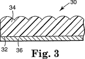
図3はなお別の適する型のマイクロレンズシート材料を示す。このシート材料は、第1および第2の広い面を有する透明な平凸または非球面下地材20を含み、第2面32は実質的に平面であり第1面は実質的に半球状または半非球状マイクロレンズ34のアレーを有する。マイクロレンズの形状および下地材の厚さは、アレーに入射する平行光線がほぼ第2面で収束するように選択される。材料層36は第2面上に供給される。この種類のシート材料は、例えば、米国特許第5,254,390号に記載されており、現在、3M社から2600シリーズ3Mセキュアーカードレセプターのブランド表示の下で市販されている。
【0015】
シート材料のマイクロレンズは、好ましくは、画像形成が起こるように画像形成屈折性表面を有し、一般に、これは曲線状のマイクロレンズ表面により提供される。曲線状表面のために、マイクロレンズは、好ましくは、均一な屈折率を有する。勾配屈折率(GRIN)を提供する他の有用な材料は、光を屈折させるために曲線状表面を必ずしも必要としない。マイクロレンズ表面は、好ましくは、本来球状であるが、しかし、非球状表面も許容可能である。マイクロレンズは、実際の画像が屈折表面により形成されるならば、円柱状または球状のようなあらゆる対称性を有することが可能である。マイクロレンズそれら自体は、円形の平凸小型レンズ、円形の二重凸状小型レンズ、ロッド、微小球、ビーズ、または円柱形小型レンズなどの独立した形態から成ることができる。マイクロレンズを形成することができる材料には、ガラス、ポリマー、無機物、結晶、半導体およびこれらおよび他の材料の組合せが挙げられる。非独立的なマイクロレンズ要素も用いることが可能である。従って、複製または浮き彫り加工から形成されるマイクロレンズ(そこではシート材料の表面が形状変更されて画像化特性を持つくりかえし型プロフィールを生成する)も用いることができる。
【0016】
可視光線および赤外線の波長にわたり1.5〜3.0間の均一な屈折率を持つマイクロレンズは、最も有用である。適するマイクロレンズ材料は、可視光線の最小吸収を有し、エネルギー源が感光層を画像化するために用いられる実施形態において、材料はまたエネルギー源の最小吸収を示すことが望ましい。マイクロレンズが独立的であろうがくりかえし型であろうが、且つマイクロレンズが作製される材料にかかわらず、マイクロレンズの屈折力は、好ましくは、屈折性表面上に入射する光線が屈折し、マイクロレンズの反対側上に収束するようなものである。さらに詳細には、光線はマイクロレンズの裏側表面上またはマイクロレンズに近接する材料上のいずれかに収束する。材料層が感光性である実施形態において、マイクロレンズは、好ましくは、その層上の適切な位置で縮小された実際の画像を形成する。約100〜800倍での画像の縮小は、特に、良好な解像度を有する画像を形成するために有用である。マイクロレンズシート材料の前表面に入射するエネルギーが、好ましくは感光性である材料層上に収束するように必要な収束条件を提供するためのマイクロレンズシート材料の構築は、この節の初めに参照した米国特許において記載されている。
【0017】
15マイクロメートル〜275マイクロメートルの範囲の直径を持つ微小球が好ましいが、しかし、他サイズの微小球も用いることが可能である。良好な合成画像解像度は、比較的短い間隔で微小球層から空間的に離れて現れるようになる合成画像用の前述の範囲のより小さい側の直径を有する微小球を用いること、およびより大きな間隔で微小球層から空間的に離れて現れるようになる合成画像用のより大きな微小球を用いることにより得ることができる。微小球用に示されたものに比肩できる小型レンズ寸法を有する、平凸状、円柱状、球状または非球状マイクロレンズなどの他のマイクロレンズは、類似の光学的効果を生み出すと期待することができる。
【0018】
II.材料層
上述のように、材料層はマイクロレンズに近接して提供される。観察者により反射または透過光下で見られる場合、複数のマイクロレンズと結びついた材料中に形成される個々の画像は、シート材料の上、平面上、および/または下に現れる合成画像を提供する。他の方法も用いることが可能であるが、こうした画像を提供するための好ましい方法は感光材料を材料層として提供し、光照射を用いてその材料を望ましいやり方において画像を提供するように変更することである。従って、本発明はそれによって限定されないが、マイクロレンズに近接する材料層の残っている課題は感光材料層に大きく関連して提示される。
【0019】
本発明に有用な感光材料には、金属、高分子および半導体材料およびこれらの混合物の皮膜およびフィルムが挙げられる。本発明に関連して用いられるように、所定レベルの可視光線または他の光の照射にさらされると露出された材料の様子が変化してその照射にさらされなかった材料とのコントラストを提供する場合に、材料は「感光性」である。従って、それによって創造された画像は、組成的変化、材料の除去またはアブレーション、相変化、または感光皮膜の重合の結果であり得る。いくつかの感光金属フィルム材料の例には、アルミニウム、銀、銅、金、チタン、亜鉛、錫、クロム、バナジウム、タンタル、およびこれら金属の合金が挙げられる。これらの金属は、一般に、金属本来の色と光への露出後の金属変性色間の差異によるコントラストを提供する。画像は、また、上述のようにアブレーションによるか、または画像が材料の光学的変性により提供されるまで材料を加熱する照射によって提供することが可能である。例えば、米国特許第4,743,526号には金属合金を加熱して色変化を提供することが記載されている。
【0020】
金属合金に加えて、金属酸化物および金属亜酸化物も感光材料として用いることができる。このクラスの材料には、アルミニウム、鉄、銅、錫およびクロムから形成される酸化物化合物が挙げられる。硫化亜鉛、セレン化亜鉛、二酸化ケイ素、酸化錫インジウム、酸化亜鉛、フッ化マグネシウムおよびケイ素などの非金属材料も、本発明に有用である色または対照を提供することができる。
【0021】
多層の薄膜材料も独特の感光材料を提供するために用いることができる。これらの多層材料は、色またはコントラスト剤の出現または除去により対比変化を提供するように設定することができる。代表的な構築物には、特定の照射波長により画像化するように(例えば色の変化により)設計される光学的スタックまたは同調キャビティが挙げられる。一つの特定例が、誘電ミラーとしての氷晶石/亜鉛硫化物(Na3AlF6/ZnS)の使用を開示している米国特許第3,801,183号に記載されている。別の例は、クロム/ポリマー(プラズマ重合ブタジエンなど)/二酸化ケイ素/アルミニウムから成る光学的スタックであり、これらの層の厚さは、クロムに対して4nm、ポリマーに対して20nm〜60nmの間、二酸化ケイ素に対して20nm〜60nmの間、およびアルミニウムに対して80nm〜100nmの間の範囲であり、およびそこでの個々の層厚さは可視スペクトルにおける特定の色反射率を提供するために選択される。薄膜同調キャビティは前に検討した単一層薄膜のいずれとも一緒に用いることができるであろう。例えば、約4nm厚さのクロム層および約100nm〜300nmの間の二酸化ケイ素層を持つ同調キャビティであって、二酸化ケイ素層の厚さは照射光の特定の照射波長に反応して色画像化されて提供するように調整される。
【0022】
本発明に有用な感光材料には、サーモクロミック材料も挙げられる。「サーモクロミック」は温度変化にさらされる場合に色を変える材料のことを指す。本発明において有用なサーモクロミック材料の例は米国特許第4,424,990号に記載されており、炭酸銅、チオ尿素を伴う硝酸銅、およびチオール、チオエーテル、スルホキシド、およびスルホンなどの硫黄含有化合物を伴う炭酸銅が例として挙げられる。他の適するサーモクロミック化合物の例には、水和硫酸塩およびホウ素の窒化物、アルミニウム、およびビスマス、およびホウ素、鉄、および燐の酸化物および水和酸化物が挙げられ、米国特許第4,121,011号に記載されている。
【0023】
当然なこととして、材料層が照射源を用いて画像化されようとしていない場合、次に材料層は感光性であり得るがそれを必要とはしない。しかし、感光材料は製造の容易さが好ましく、そして、好ましくは適する照射源も用いられる。
【0024】
III.照射源
上述のように、マイクロレンズに近接する材料層上に画像パターンを提供する好ましいやり方は、感光材料を画像化するために照射源を用いることである。望ましい輝度および波長の照射を提供するあらゆるエネルギー源が、本発明の方法により用いることができる。200nm〜11マイクロメートルの間の波長を有する照射を提供することができる素子は特に好ましいと信じられる。本発明に有用な高ピーク電力照射源の例には、エキシマーフラッシュランプ、無抵抗Q−スイッチ型マイクロチップレーザー、およびQ−スイッチ型ネオジムドープ−イットリウムアルミニウムガーネット(Nd:YAGと短縮される)、ネオジムドープ−イットリウムリチウムフッ化物(Nd:YLFと短縮される)およびチタンドープ−サファイア(Ti:サファイアと短縮される)レーザーが挙げられる。これらの高ピーク電力源は、アブレーション−材料の除去を通して、または多光子吸収工程において画像を形成する感光材料により最も有用となる。有用な照射源の他の例には、半導体レーザー、イオンレーザー、非Q−スイッチ型固体レーザー、金属蒸気レーザー、ガスレーザー、アーク灯などの低ピーク電力および高電力白熱光源を与える素子が挙げられる。これらの供給源は、感光媒体が非アブレーション的方法により画像化される場合に特に有用である。
【0025】
すべての有用な照射源に対して、照射源からのエネルギーはマイクロレンズシート材料に向けて当てられ、エネルギーの高度分散光を与えるように制御される。電磁スペクトルの紫外線、可視、および赤外線部分におけるエネルギー源のために、光線は適切な光学的要素により制御され、これらの例は図14、図15、および図16に示されると共に、以下により詳細に説明される。一つの実施形態において、通常光学系列と呼ばれる光学的要素のこの配列の要求事項は、光学系列が所期の角度でマイクロレンズおよび結果として材料層を照射するように適切な発散または散らばりを伴ってシート材料に向け光線を当てることである。本発明の合成画像は、好ましくは、0.3以上の開口数(最大分散光の半角のサインとして定義される)を持つ光発散素子を用いることにより得られる。より大きな開口数を持つ光発散素子は、より大きな視角、およびより大きな範囲の画像仮現運動を有する合成画像を生成する。
【0026】
IV.画像化法
本発明による代表的な画像化法は、レンズを通してのレーザーからの平行光線をマイクロレンズシート材料に向けて方向付けることから成る。さらに以下に説明するように、浮遊画像を有するシート材料を創造するために、光線は高開口数(NA)を持つ分散レンズを通して透過されて高度に分散された光の円錐体を生成する。高NAレンズとは0.3以上のNAを有するレンズである。微小球の照射感光皮膜側は、光円錐体の軸(光学軸)がマイクロレンズシート材料の平面に垂直であるように、レンズからの位置を合わせる。
【0027】
個々のマイクロレンズはそれぞれ光学軸に対して独特な位置を占めるので、各マイクロレンズに侵入する光線は互いのマイクロレンズ上に入射する光に比べて独特の入射角を有する。従って、光は各マイクロレンズにより材料層上の独特な位置に透過され、独特の画像を生成する。さらに正確には、単一光パルスは材料層上に単一の画像化ドットしか生成しないので、そこで隣接する各マイクロレンズの画像を提供するために、多パルス光を用いて多画像化ドットからの画像を創造する。各パルスに対して、光学軸は前パルス間の光学軸の位置に比べて新しい所に位置付けられる。これらのマイクロレンズに対する光学軸位置の連続的な変化は、対応した各マイクロレンズ上への入射角、および、従ってそのパルスにより材料層中に創造された画像化ドットの位置の変化をもたらす。結果として、微小球の裏側に収束する入射光は、感光層中の選択されたパターンを画像化する。各微小球の位置がすべての光学軸に対して独特であるので、各微小球に対して感光材料中に形成される画像はすべての他の微小球に関係する画像とは異なる。
【0028】
浮遊合成画像を形成するための別の方法は、レンズアレーを用いて高度に分散された光を生成してマイクロレンズ化材料を画像化することである。レンズアレーは、すべてが平面空間に整列された高開口数を持つ多数の小レンズから成る。アレーが光源により照射される場合、アレーは多錐体の高度に分散された光を生成し、それぞれ個々の錐体はアレー中のその対応レンズに集中する。アレーの物理的寸法は合成画像の最大の横サイズを収容できるように選択される。アレーサイズによって、小型レンズにより形成される個々のエネルギー錐体は、あたかも個々のレンズが光パルスを受けている間アレーのすべての点で順次位置付けられているかのようにマイクロレンズ化材料を露光する。どのレンズが入射光を受け取るかの選択は反射マスクの使用によって生じる。このマスクは、露光されようとする合成画像部分に対応する透過面および画像が露光されるべきでない反射面を有する。レンズアレーの横方向範囲のせいで、画像を追跡するために多光パルスを用いることは必要ない。
【0029】
マスクを入射エネルギーで十分に照射させることにより、エネルギーが通過することを可能とするマスクの部分は、あたかも画像が単一レンズにより追跡されたかのように浮遊画像の輪郭を描く高度に分散された光の多くの個別の錐体を形成する。結果として、単一光パルスのみがマイクロレンズシート材料中の全体合成画像を形成するために必要とされる。あるいは、反射マスクの代わりに、電流測定xyスキャナーなどの光線位置付けシステムが局部的にレンズアレーを照射しアレー上に合成画像をなぞることができる。この技術によりエネルギーが空間的に局限されるので、アレー中の少しの小型レンズのみがいかなる所定の時間においても照射される。照射される小型レンズは、マイクロレンズ化材料を露光してシート材料中に合成画像を形成するために必要とされる高度に分散した光の円錐体を提供する。
【0030】
レンズアレーそれ自体は個別小型レンズから、またはエッチング法によりレンズのモノリシックアレーを生成することにより製作することができる。レンズに適する材料は、入射エネルギーの波長において非吸収性であるものである。アレー中の個々のレンズは、好ましくは、0.3より大きい開口数および30マイクロメートルより大きく10mmより小さい直径を有する。これらのアレーは、反射防止皮膜を有してレンズ材料への内部損傷を引き起こし得る背面反射の影響を減少させることが可能である。加えて、有効な負の焦点距離およびレンズアレーに相当する寸法を有する単一レンズも、アレーを離れる光の発散を増大するために用いることが可能である。モノリシックアレー中の個々の小型レンズの形状は、高開口数を有し、約60%を超える大きな充填比を提供するために選択される。
【0031】
図4はマイクロレンズシート材料に侵入する発散エネルギーの図式的な略図である。画像Iが上または中で形成される材料層の部分は、各マイクロレンズが異なる視界から入射エネルギーを「見る」ので、各マイクロレンズに対して異なる。従って、独特の画像は各マイクロレンズと結びつく材料層中に形成される。
【0032】
画像化後、拡大対象物の寸法に応じて、対象物の完全なまたは部分的な画像が各微小球の後ろの感光材料中に存在する。実際の対象物が微小球の後ろで画像として再生産される程度は、微小球上に入射するエネルギー密度に応じて決まる。拡大対象物の部分は、それらの微小球上に入射するエネルギーがその材料を修正するために必要とされる照射レベルよりも低いエネルギー密度を有するようにマイクロレンズの領域から十分な距離を取ることが可能である。さらに、空間的に拡大された画像に対して、固定NAレンズにより画像化する場合、シート材料のすべての部分が拡大対象物のすべての部分に対する入射光にさらされるとは限らない。結果として、対象物のそれらの部分は感光媒体中では修正されなくて、対象物の部分画像のみが微小球の後ろに現れる。図5は個々の微小球に近接する感光層中に形成される標本画像を表すマイクロレンズシート材料の断面透視図であり、さらに、記録された画像は合成画像の完全な複製から部分的な複製までの範囲にあることを示す。図6および図7は本発明により画像化されたマイクロレンズシート材料の光学顕微鏡写真であり、感光層はアルミニウム層である。その中に示されるようにいくつかの画像は完全であり、他は不完全である。
【0033】
これらの合成画像は、不完全および完全の両方であり、すべて実際の対象物から異なる視界を持つ多くの画像を一緒に総合化した結果と考えることもできる。多くの独特の画像は、それらのすべてが対象物を「見る」かまたは異なる視界から画像化するミニチュアレンズのアレーを通して形成される。個々のミニチュアレンズの後ろで、画像の形状およびそこから画像化エネルギー源を受け取る方向に依存する画像の透視図が材料層中に創造される。しかし、レンズの見るすべてのものが感光材料中に記録されるわけではない。レンズにより見られる画像または対象物の内、感光材料を修正するために十分なエネルギーを有する部分のみが、記録される。
【0034】
画像化しようとする「対象物」は、「対象物」の外形を描くことかまたはマスクの使用のいずれかにより強い光源の使用を通して形成される。こうして記録されて合成態様を有する画像のために、対象物からの光は広範囲の角度にわたり照射されねばならない。対象物から照射される光が対象物の単一点から来ると共に、広範囲の角度にわたり照射する場合、すべての光線は対象物についての情報を運んでいるが、しかし、情報は光線の視角からのものであるが、その単一点からのみのものである。今、光線により運ばれる通りの対象物に関する比較的完全な情報を得るために、光は対象物を構成する点の収集から広範囲の角度にわたり照射しなければならないことを考察する。本発明において、対象物から発散する光線の角度の範囲は、対象物とマイクロレンズ材料の間に置かれた光学要素により制御される。これらの光学要素は合成画像を生成するために必要な最適範囲の角度を与えるように選択される。光学要素の最善の選択は光の円錐体をもたらし、それによって円錐体の頂点は対象物の位置で止まる。最適円錐角度は約40度より大きい。
【0035】
対象物はミニチュアレンズにより縮小され、対象物からの光はミニチュアレンズの裏側に接触するエネルギー感光皮膜上に収束される。収束点またはレンズの裏側での画像の実際の位置は、対象物から生じる入射光線の方向に応じて決まる。対象物上の点から発散する光の各円錐体はミニチュアレンズの一部を照射し、十分なエネルギーにより照射されたミニチュアレンズのみが対象物のその点の恒久的な画像を記録する。
【0036】
幾何光学は、本発明による種々の合成画像の形成を説明するために用いられる。前述のように、以下に記載される画像化法が本発明の好ましいが排他的ではない実施形態である。
【0037】
A.シート材料の上に浮遊する合成画像を創造すること
図8に関して、入射エネルギー100(本例においては光)は、光源中のあらゆる非均一性を均質化するために光拡散器101上に導かれる。拡散的に散乱された光100aは光コリメータ102により捕捉され平行化され、光コリメータ102は均一に分布した光100bを分散レンズ105aに導く。分散レンズから、光線100cがマイクロレンズシート材料106に向けて分散していく。
【0038】
マイクロレンズシート材料106に侵入する光線のエネルギーは個々のマイクロレンズ111により材料層(説明のための実施形態中の感光皮膜112)上に収束される。この収束されたエネルギーは感光皮膜112を修正して、光線と感光皮膜間の相互作用に応じて決まる画像、サイズ、形状、および外見を提供する。
【0039】
図8に示す配置は、レンズを通して後ろ側に延長する場合に分散光100cが分散レンズの焦点108aで交差するであろうから、以下に説明するようにシート材料の上に浮遊するように観察者には見える合成画像を有するシート材料を提供するであろう。つまり、仮定の「画像線」が各微小球を通して材料層から描かれ分散レンズを通して逆行させられるならば、それらは合成画像が現れる場である108aで収束するであろう。
【0040】
B.シート材料の上に浮遊する合成画像を見ること
合成画像を有するシート材料は、観察者と同じ側(反射光)、または観察者とはシート材料の反対側(透過光)、または両方からシート材料に侵入する光を用いて見ることが可能である。図9は、反射光下で見る場合観察者Aの肉眼にシート材料の上に浮いて見える合成画像の略図である。肉眼は正常な視覚に直すことが可能であるが、しかし、例えば拡大または特別のビュアによって助けてもらえるものではない。画像化シート材料が平行化または拡散することが可能である反射光により照射される場合、光線は、光線が衝突した材料層により決定されるやり方で画像化シート材料から逆反射される。定義により、材料層中に形成される画像は材料層の非画像化部分とは違って見え、従って画像は認知することができる。
【0041】
例えば、光L1は材料層により反射されて観察者に向かって戻ってくることが可能である。しかし、材料層は光L2をそれらの画像化部分から観察者に向けて反射して戻すことはうまくできないか、または全くできない。従って、観察者は、108aでのそれらの集積が108aでシート材料の上に浮くように見える合成画像を創造する光線がないことを認知することが可能である。簡単に言えば、光は画像化部分を除く全体シート材料から反射することが可能であり、このことは比較的暗い合成画像が108aで現れることを意味する。
【0042】
非画像化材料が入射光を吸収するかまたは透過させること、および画像化材料が合成画像を提供するために必要とされる対照効果を提供するために入射光をそれぞれ反射するかまたは部分的に吸収することもまた可能である。それらの環境下での合成画像は、比較的暗く見えるであろうシート材料の残分と比較して比較的明るい合成画像として見られるであろう。焦点108aで画像を創造するものが実際の光であり、光の不在ではないので、この合成画像は「実際の画像(リアルイメージ)」と呼ぶことが可能である。これら可能性をもった種々の組合せは要望通りに選択することができる。
【0043】
ある種の画像化シート材料は、また、図10に見られるように透過光により見ることができる。例えば、材料層の画像化部分が半透明であり、非画像化部分がそうでない場合、次に大部分の光L3は材料層により吸収されるかまたは反射されるが、一方で透過光L4は材料層の画像化部分を通過し、マイクロレンズにより焦点108aに向けて進む。合成画像は焦点で見られ、それは本実施例においてシート材料の残分よりも明るく見られる。焦点108aで画像を創造するものが実際の光であり、光の不在ではないので、この合成画像は「実際の画像」と呼ぶことが可能である。
【0044】
あるいは、材料層の画像化部分が半透明でないがしかし材料層の残分がそうである場合、次に、画像部分における透過光の不在はシート材料の残分よりも暗く見える合成画像を提供する。
【0045】
C.シート材料の下に浮遊する合成画像を創造すること
観察者から反対側のシート材料上に浮遊するように見える合成画像も提供することが可能である。シート材料の下に浮くこの浮遊画像は、図8に示す発散レンズ105の代わりに収束レンズを用いることにより創造することができる。図11に関して、入射エネルギー100(本例においては光)は、光源中のあらゆる非均一性を均質化するために光拡散器101上に導かれる。散乱光100aは次に光コリメータ102中に収集、平行化され、光コリメータ102は光100bを集束レンズ105bに導く。集束レンズから、光線100dが収束レンズと収束レンズの焦点108bの間に置かれるマイクロレンズシート材料106上に入射する。
【0046】
マイクロレンズシート材料106に侵入する光線のエネルギーは個々のマイクロレンズ111により材料層(説明のための実施形態中の感光皮膜112)上に収束される。この収束されたエネルギーは感光皮膜112を修正して、光線と感光皮膜間の相互作用に応じて決まる画像、サイズ、形状、および外見を提供する。図11に示す配置は、シート材料を通して延長する場合に収束光100dが集束レンズの焦点108bで交差するであろうから、観察者には以下に説明するようにシート材料の下に浮遊するように見える合成画像を有するシート材料を提供するであろう。つまり、仮定の「画像線」が各微小球を通しておよび各マイクロレンズと結びつく材料層中の画像を通して収束レンズ105bから描かれるならば、それらは合成画像が現れる場である108bで収束するであろう。
【0047】
D.シート材料の下に浮遊する合成画像を見ること
シート材料の下に浮いて見える合成画像を有するシート材料は、また、反射光、透過光、または両方から見ることができる。図12は、反射光下で見る場合シート材料の下に浮いて見える合成画像の略図である。例えば、光L5は材料層により反射されて観察者に向かって戻ってくることが可能である。しかし、材料層は光L6をそれらの画像化部分から観察者に向けて反射して戻すことはうまくできないか、または全くできない。従って、観察者は、108bでそれらの集積が108bでシート材料の下に浮くように見える合成画像を創造する光線がないことを認知することが可能である。簡単に言えば、光は画像化部分を除く全体シート材料から反射することが可能であり、このことは比較的暗い合成画像が108bで見られることを意味する。
【0048】
非画像化材料が入射光を吸収するかまたは透過させること、および画像化材料が合成画像を提供するために必要とされる対照効果を提供するために入射光をそれぞれ反射するかまたは部分的に吸収することもまた可能である。それらの環境下での合成画像は、比較的暗く見えるであろうシート材料の残分と比較して比較的明るい合成画像として見られるであろう。これら可能性の種々の組合せは要望通りに選択することができる。
【0049】
ある種の画像化シート材料は、また、図13に見られるように透過光により見ることができる。例えば、材料層の画像化部分が半透明であり、非画像化部分がそうでない場合、次に大部分の光L7は材料層により吸収されるかまたは反射されるが、一方で透過光L8は材料層の画像化部分を通過する。入射光の方向に戻る本明細書において「画像線」と呼ばれる光線の延長は、108bでの合成画像の形成をもたらす。合成画像は焦点で視覚的にはっきりと理解でき、それは本実施例においてシート材料の残分よりも明るく見られる。
【0050】
あるいは、材料層の画像化部分が半透明でないがしかし材料層の残分がそうである場合、次に、画像部分における透過光の不在はシート材料の残分よりも暗く見える合成画像を提供する。
【0051】
E.複合画像
本発明の原理により作製される合成画像は、それらが長さおよび幅を有し、シート材料の下か、平面中か、または上のいずれかに現れることを意味する2次元か、またはそれらが長さ、幅、および高さを有することを意味する3次元的に現れることが可能である。3次元合成画像は、シート材料の下または上のみに現れるか、または要望通りのシート材料の下、平面中、および上の組合せにおいて現れることが可能である。用語「シート材料の平面中」は、一般に、シート材料が平らに置かれる場合のシート材料の平面のみを意味する。すなわち、平らでないシート材料は、また、少なくとも部分的にその用語が本明細書において用いられる通りの「シート材料の平面中」に現れる合成画像を有することができる。
【0052】
3次元合成画像は単一焦点で現れるのではなく、むしろシート材料の片側からまたはシート材料を通して他端のポイントまでの範囲に及ぶ焦点を持つ焦点の連続体を有する画像の合成物として現れる。これは、好ましくは、多焦点で材料層を画像化するためにシート材料またはエネルギー源のいずれかを他の一方に対して連続的に動かすことにより(多数の各種レンズを提供することよりも)達成される。得られる空間複合画像は本質的に多くの個々のドットから成る。この画像はシート材料の平面に対して3デカルト座標のいずれにおいても空間的広がりを有することができる。
【0053】
別の型の効果において、合成画像は、それが消えるマイクロレンズ化シート材料の領域中に移動させることができる。この型の画像は、一応は、不透明マスクをマイクロレンズ化材料と接触させて置きマイクロレンズ化材料の一部に対して部分的に画像化光を遮断することを追加することにより、空中浮遊例に類似したやり方で作製される。こうした画像を見る場合、画像化光が接触マスクにより減少されるか排除されるかのいずれかである領域中に移動するように画像を作製することができる。画像はその領域中に「消える」ように見える。
【0054】
本発明により形成される合成画像は、観察者がシート材料の平面から視点軸間の広範囲の角度にわたり合成画像を見ることができることを意味する極めて広範囲な視角を有することができる。開口数0.64を持つ非球面レンズを用いる場合、平均直径約70〜80マイクロメートルを有する単層のガラス微小球から成るマイクロレンズシート材料中に形成される合成画像は、その中心軸が入射エネルギーの光学軸により決定される円錐視界内で見ることができる。周辺光下で、そのように形成される合成画像は約80〜90度角度一杯の円錐体にわたり見ることが可能である。発散性が少なくより低いNAを持つ画像化レンズを利用すると、より小さな半角円錐体を形成することができる。
【0055】
本発明の方法により形成される画像は、限定された視角を有するものも構築することができる。換言すれば、画像は、特定の方向、またはその方向の微小角度変更から見る場合にのみ見られる。こうした画像は、最終非球面レンズ上に入射する光がレンズの一部分のみをレーザー照射により放射するように調整することを除いて、以下の実施例1に記載される方法と同様に形成される。入射エネルギーによるレンズの部分的充填は、マイクロレンズ化シート材料上に入射する分散光の限定された円錐体をもたらす。アルミニウム被覆マイクロレンズシート材料に対して、合成画像は明るいグレーの背景上に暗いグレーの画像として限定された視角円錐体内にのみ現れる。画像はマイクロレンズシート材料に比べて浮いているように見える。
【0056】
〔実施例〕
本発明は、便宜的に特定の図面を参照できる以下の実施例によりさらに説明される。
【0057】
実施例1
この実施例は、アルミニウム材料層を持つレンズ埋め込みシート材料、およびシート材料の上に浮いて見える合成画像を説明する。浮遊画像を形成するために図14に示す型の光学系を用いた。光学系は、その基本波長1.06マイクロメートルでQ−スイッチ様式において操作するSpectra Physics Quanta−Ray(商標)DCR−2(10)Nd:YAGレーザー300から成る。このレーザーのパルス幅は一般に10〜30nsの間である。レーザー後、99%反射型反射鏡302、すりガラス拡散器304、5Xビーム拡大望遠鏡306、および開口数0.64および焦点距離39.0mmを持つ非球面レンズ308によりエネルギーを再方向付けした。非球面レンズ308からの光をXYZ試料台310に向けて導入した。試料台は三つの線形台から成り、ペンシルバニア州、ピッツバーグのAerotech Inc.からATS50060のブランドで市販されている。一つの線形台は非球面焦点とマイクロレンズシート材料間の軸(z軸)に沿って非球面レンズを動かすために用い、他の二つの台は光学軸に対して互いに直交する二つの水平軸においてシート材料を動かすことを可能とした。
【0058】
レーザー光をすりガラス拡散器304に向けて導入して熱レンズ化により生じるあらゆるビーム不均質性を排除した。拡散器に密接した5Xビーム拡大望遠鏡306により拡散器からの分散光を平行化し、光線を拡大して非球面レンズ308を充填した。
【0059】
この実施例において、レンズの焦点がマイクロレンズシート材料312の上1cmであるように、XYZ試料台のXY平面上に非球面レンズを置いた。シート材料の平面でのエネルギー密度を制御するために、カナダ、ケベック州、セント−フェイのGentec,Inc.から機械式マスクを有しED500のブランドで市販されている開口部を備えた電力計を用いた。非球面レンズの焦点から1cmの電力計の照射面にわたり約8ミリジュール/平方センチメートル(8mJ/cm2)を得るように、レーザー出力を調整した。80nm厚さのアルミニウム感光層を持つレンズ埋め込みシート材料312の試料を、アルミニウム被覆側が非球面レンズ308から顔をそらせるようにXYZ試料台310に貼った。
【0060】
ペンシルバニア州、ピッツバーグのAerotech Inc.からU21のブランドで市販されている制御器は、XYZ試料台312の動きに対する必要な制御信号およびレーザー300のパルス化用制御電圧を提供した。x−y−z調整情報、移動命令、および画像生成のために必要なレーザー発射命令を有する制御器中にCADファイルを導入することにより台を動かした。マイクロレンズ化材料の上の空間中に画像を描くためにレーザーのパルス化によってX、YおよびZ台の動きを調整することにより、不規則な複合合成画像を形成した。レーザーパルス繰返し数10Hzのために、台速度を50.8センチメートル/分に調整した。これによりマイクロレンズに近接するアルミニウム層中に連続複合線が形成された。
【0061】
マイクロレンズ化シート材料を周辺光の中で見る場合、画像は明るいグレー背景に対して暗いグレーであった。焦点とビーズ状シート材料表面間の固定された1cm間隔に対して、得られた画像はシート材料の上約1cmに浮いて見える平面的な合成画像であった。さらに、合成画像は観察者の視野に関して合理的に大きな動きを示すので、そこで観察者は視角に応じて合成画像の異なる態様を容易に見ることができた。
【0062】
実施例2
この実施例において、マイクロレンズシート材料の下に浮いて見える合成画像を形成するために、透過性ミラー感光層を持つレンズ露出シート材料構造物を用いた。実施例1において用いた光学系をこの実施例においても用いた。レンズがほとんどマイクロレンズシート材料と接触するように、マイクロレンズ化シート材料を非球面レンズ308に対して位置付けた。レーザー出力を非球面レンズ直下で約14mJ/cm2を達成するように調整した。レンズ露出シート材料は、微小球の片側上に蒸着した硫化亜鉛(ZnS)誘電ミラーを伴う、米国特許第3,801,183号に記載されているような部分的に埋め込まれた微小球から成った。ZnS層の厚さは名目上60nmであった。実施例1にあるように、レーザーを10Hzで操作し、シート材料を50.8cm/分で動かすことにより、マイクロレンズ化シート材料中に連続複合線の形成を生じた。「球」パターン(4内接円弧を持つ円)を台システムにより描いた。
【0063】
周辺光下で、球は白/黄背景に対して暗い画像として現れた。暗い合成画像はシート材料の下約39mmに浮いて見えた。合成画像の位置は、この実施例ではレンズの後ろ約39mmに関連する非球面レンズの焦点位置に対応した。
【0064】
実施例3
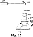
この実施例は、単一非球面レンズの代わりにレンズアレーを用いて、アルミニウム感光層を持つレンズ露出シート材料中に合成画像を形成することを説明する。浮遊合成画像を形成するために、図15に示す型の光学系を用いた。光学系は、Q−スイッチ型レーザー300、99%反射型ミラー302、光学拡散器304、およびビーム拡大望遠鏡306から成った。この実施例において用いた光学系のこれらの構成要素は実施例1に記載されているものと同じである。また、この実施例の光学系中に含まれるものには、2次元レンズアレー407、反射マスク409および負の双凹レンズ411があった。反射マスク409の面は、レーザー照射にさらされようとするマイクロレンズ化材料412の面と合致するように透過性であり、一方残りのマスクの表面は半透過性または反射性であった。レンズアレー407は、アラバマ州、ハンツビルのMEMS Optical,LLCから3038のブランドで市販されている石英ガラス反射型マイクロレンズアレーから成った。この密に充填された球面レンズアレーを、直径75mmおよび焦点距離マイナス150mmを有する負の双凹レンズ411とほとんど接触するように置いた。80nm厚さのアルミニウム感光層を持つレンズ露出シート材料412を、負の双凹レンズ411の25mm内に置いた。マイクロレンズ化材料を、マイクロレンズアレーおよび負の双凹レンズの組合せ光学通路の焦点距離から約1cmに置いた。レーザーからの出力を、マイクロレンズ化シート材料の露出レンズ表面の界面で約4mJ/cm2が生成されるように調整した。単一レーザーパルスを活性化して全体画像に露光した。
【0065】
周辺光下で見る場合、得られた画像化マイクロレンズ化シート材料は、シート材料の上約1cmに浮いて見える画像を示した。画像は明るいグレー背景に対して暗いグレーに見えた。
【0066】
実施例4
この実施例において、分散光源は散乱源からの反射により得た。散乱反射器は約5mm直径のセラミックビーズから成った。図16に示す型の光学系をこの実施例において用いた。それは、実施例1に記載されたものと同じQ−スイッチ型Nd:YAGレーザー500、次に入射レーザービームのサイズを約1mm直径に減少させる望遠鏡502から成った。次に、マイクロレンズシート材料512に面するセラミックビーズの半球504の約1/4を照射するために、光を通常から十分に外れた角度でセラッミックビーズ504上に侵入させた。これは赤外線カメラを通して散乱照射を見ることにより確認された。
【0067】
セラミックビーズ504をXY試料台510の上約25mmの距離に位置付けた。レーザーからの入射光が試料台に平行になるように調整した。80nmアルミニウム感光層を持つ埋め込みレンズシート材料512をXY試料台510に貼り、制御器は試料台およびレーザーへの制御信号を提供した。マイクロレンズシート材料の表面で約8mJ/cm2が生成されるようにレーザー出力を調整した。マイクロレンズ化シート材料512の表面に対して最も均質な光を得るためにセラミックビーズ504の光照射を調整した。XY試料台510を10Hzのレーザーパルスにより50.8cm/分で動かした。複合画像を試料台により描く一方でマイクロレンズ化シート材料をセラミック反射器からの散乱照射にさらした。
【0068】
周辺光において、合成画像はシート材料の上約25mmに浮き、明るいグレー背景に対して暗いグレーに見えた。観察者の視点を基準にして画像は大きな動きを持った。透過光下、発光合成画像はシート材料の上約25mmに浮いた。
【0069】
実施例5
この実施例において、レンズ埋め込みシート材料の材料層は、可視スペクトルにおける特定色に同調させた多層光学スタックから成った。マイクロレンズ化基板の一つの面上に、薄膜層が真空蒸発およびプラズマ重合により蒸着して、クロム/プラズマ重合ブタジエン/二酸化ケイ素/アルミニウムから成る層配列が得られ、クロム層は埋め込みレンズに近接していた。可視スペクトルの赤、緑、および青部分の色を得るために個々の材料の厚さを調整した。第1表は調製された個々の材料の特定の厚さを示す。
【0070】
【表1】

次に、被覆マイクロレンズ下地材を積層材料と接触している多層構造のバッキングに積層した。次に、マイクロレンズシート材料のライナーを除去して上記表により与えられる色を有する埋め込みレンズの前表面にさらした。
【0072】
実施例1に記載された光学系を用いてこの実施例の試料を画像化した。この実施例において、非球面レンズの焦点をマイクロレンズシート材料の1cm上に位置付けた。マイクロレンズシート材料の表面で5mJ/cm2のエネルギー密度が得られるようにレーザー出力を調整した。多層スタックの光学特性を光照射領域において修正した。実施例1において記載したものと同じやり方で多層スタック中に画像を提供するために球パターンを描いた。
【0073】
周辺光において、照射領域はマイクロレンズ化シート材料の背景色に対して明るい黄からオレンジの色に見えた。すべての合成画像はシート材料の上に浮き、観察者を基準にして動いて見えた。
【0074】
実施例6
この実施例はカラー合成画像を生成するための感光層としての多層同調スタックの第2タイプを説明する。レンズ埋め込みシート材料から成るマイクロレンズ化下地材上に光学スタックを調製した。マイクロレンズ化下地材の一つの面上に薄膜層を真空蒸発により蒸着させて、以下の第2表に示すようなクロム/氷晶石/アルミニウム(Cr/Na3AlF6/Al)、クロム/二酸化ケイ素/アルミニウム(Cr/SiO2/Al)、またはクロム/フッ化マグネシウム/アルミニウム(Cr/MgF2/Al)から成る層配列を得た。可視スペクトル中の多様な色を得るために誘電体、SiO2、Na3AlF6およびMgF2の厚さを調整した。第2表は種々の試料中に調製された個々の材料の特定厚さを示す。
【0075】
【表2】
次に、多層が積層材料と接触するように、被覆マイクロレンズ下地材をバッキングに積層した。次に、マイクロレンズシート材料のライナーを除去して上記表により与えられる色を有する埋め込みレンズの前表面にさらした。
【0077】
実施例1に記載された光学系を用いてこれらの試料を画像化した。この実施例において、最終非球面レンズの位置をほとんど試料に接触するように位置付けしてシート材料の下に浮いて見える合成画像を提供した。第2表に示すように、それぞれの多層スタックの光学特性を恒久的に変えるであろうエネルギー密度が得られるようにレーザーエネルギーを調整した。実施例1において記載したものと同じやり方でこの材料中に画像用として英数字文字「SAMPLE」を描いた。周辺光において、マイクロレンズ化シート材料の背景色に対して白/黄輪郭を伴い暗く見えた。すべての合成画像はシート材料の下約39mmに浮き、シート材料を見る観察者を基準にして動いて見えた。
【0078】
実施例7
この実施例において、50原子%銀および50原子%亜鉛(Ag50Zn50)の相変化合金および感光層としてのクロムおよび二酸化ケイ素から成る同調二分子層スタックを用いて、カラー合成画像をレンズ埋め込みシート材料中に形成した。相変化合金は適用した光によっては除去されなかったが、一方で同調二分子層は可視電磁スペクトルの青部分におけるスペクトル反射率を増大させる。実施例5において多層スタックの薄膜層をマイクロレンズ化下地材上に蒸着させるために用いた手順と同様のやり方で、レンズ閉鎖型シート材料のスペーサ層上に感光層を蒸着させた。最初に、クロムおよび二酸化ケイ素層を、高分子スペーサ層上にそれぞれ40nmおよび260nmの厚さに真空蒸着させた。次に、80nm厚さのAg50Zn50合金層を二酸化ケイ素層上にスパッタ蒸着させた。次に、試料を積層し剥ぎ取ってマイクロレンズシート材料のクリア部分を露出させた。
【0079】
周辺(反射)光下で見る場合、シート材料はスミレ−青であるように見えた。実施例1と同じ光学系を用いてAg50Zn50感光層を画像化した。Q−スイッチ型レーザーの代わりに、波長1.06umで操作する連続波Nd:YAGレーザーをエネルギー源として用いた。光学系中の音響光学変調器の使用によりパルス幅を制御した。図14に示される型の光学系を通して一次回折ビームを送った。レンズ閉鎖型シート材料の試料をXYZ試料台に貼った。音響光学変調器中へのレーザー出力をマイクロレンズ化材料で810mWの出力を与えるように調節した。100マイクロ秒パルス幅で20Hzパルスを達成するように音響光学変調器を設定した。実施例1に記載したように、正の非球面レンズをマイクロレンズ化材料の表面の上12mmに置いた。XYZ試料台により画像を描き出し、一方でレーザー照射は感光層を露光した。
【0080】
シート材料を周辺光において見る場合、画像化領域は淡青色に見え、マイクロレンズシート材料の上約12mmに浮いた。
【0081】
実施例8
この実施例において、銅感光層を持つ複製レンズ構造物をマイクロレンズシート材料として用いた。米国特許第5,254,390号に記載されている型の複製シート材料をマイクロレンズシート材料として用いた。銅感光層をシート材料の平らな表面上に厚さ80nmに真空蒸着させた。マイクロ複製化マイクロレンズ化材料を実施例1に記載した光学系からのレーザー照射にさらした。最終非球面レンズをマイクロレンズ化材料の表面から6.5mm離れた焦点距離に位置付けた。シート材料の表面で約7mJ/cm2が得られるようにレーザー出力を調整した。レーザーを10Hzパルスに設定し、XYZ試料台の方は50.8cm/分の速度で動かした。「球」パターン(4内接円弧を持つ円)を試料の上に描いた。
【0082】
シート材料を周辺光において見る時、感光層の銅色に対して浮遊球の白い画像を見ることができた。この合成画像はシート材料の上約6mmに浮いて見えた。
【0083】
実施例9
この実施例は平面合成画像とシート材料の下に浮いて見える合成画像との組合せを説明する。80mm厚さのアルミニウム感光層を持つレンズ露出型マイクロレンズシート材料を、実施例1に記載した光学系を用いて画像化した。非球面レンズをほとんどマイクロレンズシート材料に接触させて位置決めし、試料表面で4mJ/cm2が得られるようにレーザー出力を調整した。英数字文字「SAMPLE」を描くように制御器をプログラム化した。吸収マスクを開放シート材料の上に置いた。このマスクは従来のコピー機を用いて透明シート上に英数字文字「3M」の列を印刷して作製した。英数字文字は照射を吸収するが、一方で周囲の面はレーザー照射を透過するであろう。この吸収性マスクを持つ露出レンズシート材料を、「SAMPLE」文字がマスク位置の上にわたって形成されるように位置決めした。
【0084】
周辺光において見る時、文字「SAMPLE」はシート材料の下約39mmに浮いて見えたが、一方で非露出文字「3M」はシート材料の平面中にあるように見えた。「SAMPLE」文字からの暗い文字に対して「3M」文字はただ観察できるだけだった。
【0085】
実施例10
この実施例は複合3次元画像を持つシート材料を説明する。80mm厚さのアルミニウム感光層を持つレンズ埋め込み型マイクロレンズシート材料をこの実施例に用いた。実施例1に用いた光学系を用いた。マイクロレンズ化シート材料をXYZ並進試料台のXY平面に貼り付け、一方で非球面レンズをz軸に取り付けた。非球面レンズはNA0.64および焦点距離39mmを有した。5cm長の立方体対角線(立方体の反対側の2角間の距離)を持つ等尺性立方体の外形を描くように制御器をプログラム化した。制御器にプログラム化された立方体の相対位置および方向は、合成立方体画像の一端をシート材料表面の上約5mmに置き、合成立方体画像の他端をその表面の上5.5cmに置くものであった。立方体画像は立方体の角を最も観察者に近づけて置くように方向を合わせた。
【0086】
等尺性立方体の描写の間、発散レンズとシート材料間の間隔には関係なく試料表面で8mJ/cm2の一定エネルギー密度が得られるように、レーザーからのパルス当りのエネルギーを制御した。レーザーを10Hzで操作し、X、YおよびZ試料台を50.8cm/分の速度で動かした。等尺性立方体の画像を、制御器によりマイクロレンズ化シート材料の上の空間中に連続的に描き出した。
【0087】
周辺光において見る時、等尺性合成立方画像は、表面の上5mm〜5.5cmの間に浮き、明るいグレー背景に対して暗いグレーに見えた。さらに、観察者がその視点を変えるにつれて、等尺性立方体はマイクロレンズシート材料の上の空間中に回転して見え、前には異なる視角で見えなくなっていた立方体の側面を浮き彫りにした。
【0088】
実施例11
この実施例は消失させ得る浮遊画像を説明する。すなわち、合成画像は、視角を変えることにより、視界から消えるかまたは視界に再出現するように作製することができる。80mm厚さのアルミニウム感光層を持つレンズ埋め込みシート材料を用いた。画像形成のために実施例1と同じ光学系を用い、シート材料からの非球面レンズの距離をマイクロレンズ化シート材料の上1cmの焦点距離に位置付けるように調整した。「球」パターン(4内接円弧を持つ円)を生成するように制御器をプログラム化し、試料表面で8mJ/cm2を提供するようにレーザー出力を調整した。試料それ自体の上で、半透明テープの四角断面をレンズ埋め込みシート材料の表面に貼り付けた。球画像化の間にレーザーにより画像化された面積部分が半透明テープにより覆われた部分に重なるであろうように、テープの四角断面を位置取りした。
【0089】
画像化シート材料を周辺光下で見る時、浮遊球パターンは、シート材料の上1cmに浮き、明るいグレー背景に対して暗いグレー画像として観察された。視角を変えることにより、「球」は半透明テープによりマスクされた領域中にまたはそこから移動した。球がマスクされた領域中に移動する時に、その領域に入る球の部分は消える。球がマスクされた領域から出る時に、その領域での球の部分は再度現れた。合成画像はそれが単にマスクされた領域中に入って行くにつれて次第に消えて行くというのではなく、むしろ、それがその領域に入った時に正確に完全に消えるものであった。
【0090】
本発明の合成画像を含有する画像化シート材料は独特のものであり、通常の装置で複製することは不可能である。合成画像は、パスポート、識別バッジ、識別グラフィック、およびアフィニティ・カードなどの用途に特別に挙げられるシート材料中に形成することができる。検定を必要とする書類は、識別、信憑性、および高揚のために、積層シート材料上に形成されるこれらの画像を有することができる。接着剤ありまたはなしでの積層などの従来の結合手段は、用いることが可能である。箱型電子製品、コンパクトディスク、運転免許証、文書表題、パスポートまたはブランド製品などの価値品目の供給業者は、単に本発明の多層フィルムを彼らの製品に貼り、彼らの顧客に対してそう表示された信憑性のある価値品目として承認するだけであると指示することが可能である。これらの保護を必要とする製品に対して、合成画像を含有するシート材料をそれらの構成物中に封入すること、またはこうしたシート材料を製品に付着させることによりそれらのアピール度を高めることが可能である。合成画像は、広告用、ナンバープレート用、および独特の画像の視覚表示が望ましい多くの他用途用の表示材料として用いることが可能である。
【0091】
多合成画像は同じシート材料上に形成することが可能であり、それらの合成画像は同じかまたは異なることが可能である。合成画像は、また、印刷画像、ホログラム、アイソグラム、回折格子、カイングラム、および写真などの他の従来画像と一緒に用いることが可能である。
【0092】
開示された実施形態の種々の修正および組合せは当業者に明白であり、それらの修正は特許請求の範囲に規定される本発明の範囲内にあるものと意図されている。
【図面の簡単な説明】
【図1】 「レンズ露出」マイクロレンズシート材料の拡大断面図である。
【図2】 「レンズ埋め込み」マイクロレンズシート材料の拡大断面図である。
【図3】 平凸系シートを含むマイクロレンズシート材料の拡大断面図である。
【図4】 微小球から構築されたマイクロレンズシート材料に侵入する分散エネルギーのグラフ表示を示した模式図である。
【図5】 個々の微小球に近接する材料層中に記録された標本画像を示し、さらに、記録された画像が合成画像の完全複製から部分複製の範囲にあることを示すマイクロレンズシート材料部の平面図である。
【図6】 本発明によりシート材料の上に浮いて現れる合成画像を提供するために画像化されたアルミニウムフィルムから成る感光材料層を持つマイクロレンズシート材料の光学顕微鏡写真である。
【図7】 本発明によりシート材料の下に浮いて現れる合成画像を提供するために画像化されたアルミニウムフィルムから成る感光材料層を持つマイクロレンズシート材料の光学顕微鏡写真である。
【図8】 マイクロレンズシート材料の上に浮いて現れる合成画像形成の幾何光学的表示を示した模式図である。
【図9】 シート材料を反射光の方向において見る場合に本発明のシート材料の上に浮いて現れる合成画像を有するシート材料の模式図である。
【図10】 シート材料を透過光線の方向において見る場合に本発明のシート材料の上に浮いて現れる合成画像を有するシート材料の模式図である。
【図11】 見る場合にマイクロレンズシート材料の下に浮いて現れる合成画像形成の幾何光学的表示を示した模式図である。
【図12】 シート材料を反射光の方向において見る場合に本発明のシート材料の下に浮いて現れる合成画像を有するシート材料の模式図である。
【図13】 シート材料を透過光線の方向において見る場合に本発明のシート材料の下に浮いて現れる合成画像を有するシート材料の模式図である。
【図14】 本発明の合成画像を形成するために用いられた分散エネルギーを生み出すための光学系の模式図である。
【図15】 本発明の合成画像を形成するために用いられた分散エネルギーを生み出すための第2光学系の模式図である。
【図16】 本発明の合成画像を形成するために用いられた分散エネルギーを生み出すための第3光学系の模式図である。[0001]
Field of Invention
The present invention relates to a sheet material that provides one or more composite images in which an observer feels floating in space with respect to the sheet material and the perspective of the composite image changes depending on the viewing angle.
[0002]
Background of the Invention
Sheet materials with graphic images or other indicators have been widely used as labels, especially for authenticating papers or literature. For example, sheet materials such as those described in U.S. Pat. Nos. 3,154,872, 3,801,183, 4,082,426, and 4,099,838 are vehicle license plates. It has been used as a confirmation sticker and as a protective film for driver's licenses, official documents, cassette tapes, playing cards and beverage containers. Other applications include graphic applications for identification purposes such as on patrol cars, fire trucks or other emergency vehicles with unique signs to serve for advertising display and brand uplift.
[0003]
Another form of imaging sheet material is disclosed in US Pat. No. 4,200,875 (Galanos). Galanos discloses the use of a “lens exposed high gain retroreflective sheet material” in particular where the image is formed by laser irradiation of the sheet material through a mask or pattern therein. The sheet material comprises a plurality of transparent glasses having a metallic reflective layer coated on each embedded surface of a plurality of microspheres, partially embedded in the binder layer and partially exposed on the binder. Includes microspheres. The binder layer contains carbon black which is said to minimize any stray light that enters the sheet material while being imaged. The energy of the laser light is further concentrated by the focusing effect of the microlens embedded in the binder layer.
[0004]
The image formed in Galanos retroreflective sheet material is only visible when viewing the sheet material from the same angle that the laser radiation was directed at the sheet material. In other words, it means that the image can only be viewed at a very limited viewing angle. For these and other reasons, there continues to be a desire to improve certain properties of such sheet materials.
[0005]
As early as 1908, Gabriel Lippman invented a method for generating a true three-dimensional image of a scene in a lens medium having one or more photosensitive layers. The method, known as integral photography, is also described in De Motebello, “Processing and Display of Three-Dimensional Data II” in Processing of SPIE, San Diego, 1984. In Lippmann's method, the photographic plate is exposed through an array of lenses (or “small lenses”), so that each small lens in the array seeks to be reproduced as seen from the perspective of the sheet occupied by the small lens. A miniature image of the scene is transmitted to the photographic plate. After the photographic plate is developed, an observer viewing a composite image on the plate through a small lens array will see a three-dimensional display of the photographed scene. The image can be black and white or color depending on the photosensitive material used.
[0006]
Since the image formed by the lenslet during the exposure of the plate undergoes only a single inversion of each miniature image, the resulting three-dimensional display is pseudo-mirror. That is, since the perceived depth of the image is reversed, the object looks “inside out”. This is a major disadvantage because it requires two optical inversions to correct the image. These methods are complex, including multiple exposures by a single camera, or many cameras, or multi-lens cameras, to provide multiple single scenes to record multiple scenes of the same object Requires very accurate registration of multiple images. Furthermore, any method that relies on a conventional camera requires the presence of an actual object in front of the camera. This further provides a poorly selected method for generating a three-dimensional image of a virtual object (meaning an object that exists substantially but does not actually exist). A further disadvantage of integral photography is that the composite image must be illuminated from the viewer side to form the actual image that can be viewed.
[0007]
Summary of the Invention
The present invention provides a microlens sheet material having a composite image that appears above or below the sheet material. These floating images are referred to as floating images for convenience and they can be located above or below the sheet material (as either 2D or 3D images) or on the sheet material in the plane, Or it can be a 3D image that appears below. The image can be black and white or color and can appear to move with the viewer. Unlike some holographic sheet materials, the imaging sheet material of the present invention cannot create a replica of itself. Further, the floating image (including a plurality of floating images) can be observed with the naked eye of the viewer.
[0008]
The sheet material of the present invention with composite images as described can be used for passports, ID badges, event permits, affinity cards, product identification formats, and safe and non-tamperable images in verification and authentication advertising, Identification display images in graphic applications such as brand uplifting images, police cars, fire cars or other emergency vehicles emblems that provide floating or subsidence or floating and subsidence images; kiosks, night light displays and car dash Information display images in graphic applications such as board displays; and can be used in a variety of applications such as novelty enhancement through the use of composite images on products such as business cards, tags, artwork, shoes and bottle products is there.
[0009]
The present invention further provides a novel means of forming an imaging sheet material containing the described composite image. In one embodiment, a single composite image is formed. Also disclosed are embodiments in which composite images are formed in which two or more of them appear both above and below the sheet material. Other embodiments could consist of a combination of a traditional printed image and a composite image formed according to the present invention.
[0010]
Detailed Description of the Invention
The microlens sheet material of the present invention floats or appears floating above, in the plane and / or below the sheet material, providing a composite image provided by individual images associated with many microlenses. .
[0011]
To provide a complete description of the present invention, the microlens sheet material is described in Part I below, followed by the material layer (preferably the photosensitive material layer) of such sheet material in Part II and the radiation source in Part In III, the imaging method is described in Part IV. Several examples are also provided to further illustrate various embodiments of the invention.
[0012]
I. Micro lens sheet material
The microlens sheet material capable of forming the image of the present invention comprises a microlens layer or a material layer (preferably as described below, preferably a photosensitive material or a layer disposed adjacent to one side surface of the multiple layers). One or more individual layers of microlenses having a coating). For example, FIG. 1 shows a “lens-exposed” type microlens sheet material 10 that includes a single layer of
[0013]
FIG. 2 shows another suitable type of microlens sheet material. The
[0014]
FIG. 3 shows yet another suitable type of microlens sheet material. The sheet material includes a transparent plano-convex or
[0015]
The microlens of the sheet material preferably has an imaging refractive surface so that imaging occurs, generally this is provided by a curved microlens surface. Due to the curved surface, the microlens preferably has a uniform refractive index. Other useful materials that provide a gradient index of refraction (GRIN) do not necessarily require a curved surface to refract light. The microlens surface is preferably spherical in nature, but non-spherical surfaces are acceptable. The microlens can have any symmetry, such as cylindrical or spherical, if the actual image is formed by a refractive surface. The microlenses themselves can consist of independent forms such as circular plano-convex lenslets, circular biconvex lenslets, rods, microspheres, beads, or cylindrical lenslets. Materials from which microlenses can be formed include glass, polymers, inorganics, crystals, semiconductors, and combinations of these and other materials. Non-independent microlens elements can also be used. Thus, microlenses formed from replication or embossing, where the surface of the sheet material is reshaped to create a repeat profile with imaging properties, can also be used.
[0016]
Microlenses with a uniform refractive index between 1.5 and 3.0 over visible and infrared wavelengths are most useful. Suitable microlens materials have a minimum absorption of visible light, and in embodiments where an energy source is used to image the photosensitive layer, it is desirable that the material also exhibit a minimum absorption of the energy source. Regardless of whether the microlens is independent or repeatable, and regardless of the material from which the microlens is made, the refractive power of the microlens is preferably such that light incident on the refractive surface is refracted, It converges on the opposite side of the microlens. More specifically, the light rays are focused either on the back surface of the microlens or on the material proximate to the microlens. In embodiments where the material layer is photosensitive, the microlens preferably forms a reduced actual image at the appropriate location on the layer. The reduction of the image by about 100 to 800 times is particularly useful for forming an image having good resolution. The construction of the microlens sheet material to provide the necessary convergence conditions so that the energy incident on the front surface of the microlens sheet material converges on the material layer, which is preferably photosensitive, was referenced at the beginning of this section. It is described in US patents.
[0017]
Microspheres with diameters in the range of 15 micrometers to 275 micrometers are preferred, but other sizes of microspheres can be used. Good composite image resolution uses microspheres with smaller side diameters of the aforementioned range for composite images that appear spatially away from the microsphere layer at relatively short intervals, and larger spacing Can be obtained by using larger microspheres for the composite image that appear spatially away from the microsphere layer. Other microlenses, such as plano-convex, cylindrical, spherical or non-spherical microlenses, with small lens dimensions comparable to those shown for microspheres may be expected to produce similar optical effects. it can.
[0018]
II. Material layer
As described above, the material layer is provided proximate to the microlens. When viewed by a viewer under reflected or transmitted light, the individual images formed in the material associated with the plurality of microlenses provide a composite image that appears above, on the plane, and / or below the sheet material. . While other methods can be used, a preferred method for providing such an image provides the photosensitive material as a material layer and uses light irradiation to modify the material to provide the image in the desired manner. That is. Accordingly, the present invention is not limited thereby, but the remaining problem of the material layer proximate to the microlens is presented largely in relation to the photosensitive material layer.
[0019]
Photosensitive materials useful in the present invention include coatings and films of metals, polymers and semiconductor materials and mixtures thereof. As used in connection with the present invention, exposure to a predetermined level of visible or other light exposure changes the appearance of the exposed material to provide contrast with the material not exposed to that exposure. In some cases, the material is “photosensitive”. Thus, the image created thereby may be the result of a compositional change, material removal or ablation, phase change, or polymerization of the photosensitive film. Examples of some photosensitive metal film materials include aluminum, silver, copper, gold, titanium, zinc, tin, chromium, vanadium, tantalum, and alloys of these metals. These metals generally provide contrast due to the difference between the original color of the metal and the metal modified color after exposure to light. The image can also be provided by ablation as described above, or by irradiation that heats the material until the image is provided by optical modification of the material. For example, U.S. Pat. No. 4,743,526 describes heating a metal alloy to provide a color change.
[0020]
In addition to metal alloys, metal oxides and metal suboxides can also be used as photosensitive materials. This class of materials includes oxide compounds formed from aluminum, iron, copper, tin and chromium. Non-metallic materials such as zinc sulfide, zinc selenide, silicon dioxide, indium tin oxide, zinc oxide, magnesium fluoride and silicon can also provide colors or controls that are useful in the present invention.
[0021]
Multilayer thin film materials can also be used to provide unique photosensitive materials. These multilayer materials can be set to provide contrast changes by the appearance or removal of color or contrast agents. Exemplary constructs include optical stacks or tuning cavities that are designed to image (eg, by color change) with a particular illumination wavelength. One specific example is cryolite / zinc sulfide (NaThreeAlF6No. 3,801,183, which discloses the use of / ZnS). Another example is an optical stack consisting of chromium / polymer (such as plasma polymerized butadiene) / silicon dioxide / aluminum, the thickness of these layers being between 4 nm for chromium and between 20 nm and 60 nm for polymer. , Ranges between 20 nm to 60 nm for silicon dioxide and 80 nm to 100 nm for aluminum, and the individual layer thickness therein is selected to provide a specific color reflectance in the visible spectrum Is done. The thin film tuning cavity could be used with any of the single layer thin films previously discussed. For example, a tuning cavity with a chromium layer about 4 nm thick and a silicon dioxide layer between about 100 nm and 300 nm, where the thickness of the silicon dioxide layer is color-imaged in response to a specific illumination wavelength of the illumination light. Adjusted to provide.
[0022]
The photosensitive material useful in the present invention also includes a thermochromic material. “Thermochromic” refers to a material that changes color when exposed to temperature changes. Examples of thermochromic materials useful in the present invention are described in US Pat. No. 4,424,990, which includes copper carbonate, copper nitrate with thiourea, and sulfur-containing compounds such as thiols, thioethers, sulfoxides, and sulfones. An example is copper carbonate with Examples of other suitable thermochromic compounds include hydrated sulfate and boron nitride, aluminum, and bismuth, and boron, iron, and phosphorus oxides and hydrated oxides; U.S. Pat. 121,011.
[0023]
Of course, if the material layer is not about to be imaged using an irradiation source, then the material layer may be photosensitive but does not require it. However, the light-sensitive material is preferably easy to manufacture, and preferably a suitable irradiation source is also used.
[0024]
III. Irradiation source
As mentioned above, the preferred way of providing an image pattern on the material layer proximate to the microlens is to use an illumination source to image the photosensitive material. Any energy source that provides illumination of the desired brightness and wavelength can be used with the method of the present invention. Devices that can provide radiation having a wavelength between 200 nm and 11 micrometers are believed to be particularly preferred. Examples of high peak power irradiation sources useful in the present invention include excimer flash lamps, non-resistive Q-switched microchip lasers, and Q-switched neodymium doped yttrium aluminum garnet (abbreviated as Nd: YAG), These include neodymium-doped yttrium lithium fluoride (shortened as Nd: YLF) and titanium-doped sapphire (shorted as Ti: sapphire) lasers. These high peak power sources are most useful with photosensitive materials that form images through ablation-material removal or in multiphoton absorption processes. Other examples of useful irradiation sources include devices that provide low peak power and high power incandescent light sources such as semiconductor lasers, ion lasers, non-Q-switched solid state lasers, metal vapor lasers, gas lasers, arc lamps and the like. . These sources are particularly useful when the photosensitive media is imaged by non-ablation methods.
[0025]
For all useful illumination sources, the energy from the illumination source is directed towards the microlens sheet material and is controlled to give a highly dispersed light of energy. For energy sources in the ultraviolet, visible, and infrared portions of the electromagnetic spectrum, the light rays are controlled by appropriate optical elements, examples of which are shown in FIGS. 14, 15, and 16 and are described in more detail below. Explained. In one embodiment, the requirements for this arrangement of optical elements, usually referred to as an optical series, with appropriate divergence or dispersion such that the optical series illuminates the microlens and, consequently, the material layer, at the desired angle. The application of light to the sheet material. The composite image of the present invention is preferably obtained by using a light diverging element having a numerical aperture (defined as a half-angle sign of maximum dispersion light) of 0.3 or more. A light diverging element with a larger numerical aperture produces a composite image with a larger viewing angle and a larger range of image manifestation motion.
[0026]
IV. Imaging method
An exemplary imaging method according to the present invention consists of directing parallel rays from a laser through a lens towards a microlens sheet material. As described further below, to create a sheet material with a floating image, the rays are transmitted through a dispersive lens with a high numerical aperture (NA) to produce a highly dispersed cone of light. A high NA lens is a lens having an NA of 0.3 or more. The position of the microsphere on the side of the irradiated photosensitive film is aligned with the lens so that the axis of the light cone (optical axis) is perpendicular to the plane of the microlens sheet material.
[0027]
Since each individual microlens occupies a unique position with respect to the optical axis, the light rays that enter each microlens have a unique incident angle compared to the light incident on each other microlens. Thus, light is transmitted by each microlens to a unique location on the material layer, producing a unique image. More precisely, since a single light pulse produces only a single imaging dot on the material layer, it uses multi-pulse light from multiple imaging dots to provide an image of each adjacent microlens there. Create an image. For each pulse, the optical axis is positioned at a new location relative to the position of the optical axis between the previous pulses. The continuous change in the optic axis position for these microlenses results in a change in the incident angle on each corresponding microlens, and thus the position of the imaging dots created in the material layer by the pulse. As a result, incident light that converges on the back side of the microspheres images the selected pattern in the photosensitive layer. Since the location of each microsphere is unique for all optical axes, the image formed in the photosensitive material for each microsphere is different from the image associated with all other microspheres.
[0028]
Another method for forming a floating composite image is to use a lens array to generate highly dispersed light to image the microlensed material. The lens array consists of a large number of small lenses, all having a high numerical aperture, aligned in a planar space. When the array is illuminated by a light source, the array produces multi-cone highly dispersed light, with each individual cone concentrating on its corresponding lens in the array. The physical dimensions of the array are selected to accommodate the maximum lateral size of the composite image. Depending on the array size, the individual energy cones formed by the lenslets expose the microlens material as if the individual lenses were sequentially positioned at all points of the array while receiving the light pulse. . The selection of which lens receives incident light occurs by the use of a reflective mask. The mask has a transmissive surface corresponding to the portion of the composite image that is to be exposed and a reflective surface where the image should not be exposed. Because of the lateral extent of the lens array, it is not necessary to use multiple light pulses to track the image.
[0029]
By fully illuminating the mask with incident energy, the portion of the mask that allows energy to pass through is highly dispersed light that outlines the floating image as if the image was tracked by a single lens. To form many individual cones. As a result, only a single light pulse is required to form an overall composite image in the microlens sheet material. Alternatively, instead of a reflective mask, a beam positioning system such as an amperometric xy scanner can irradiate the lens array locally and trace the composite image on the array. Since this technique spatially localizes energy, only a few small lenses in the array are illuminated at any given time. The illuminated lenslet provides the highly dispersed cone of light required to expose the microlens material to form a composite image in the sheet material.
[0030]
The lens array itself can be fabricated from individual lenslets or by creating a monolithic array of lenses by etching. Suitable materials for the lens are those that are non-absorbing at the wavelength of the incident energy. The individual lenses in the array preferably have a numerical aperture greater than 0.3 and a diameter greater than 30 micrometers and less than 10 mm. These arrays can have an antireflective coating to reduce the effects of back reflections that can cause internal damage to the lens material. In addition, a single lens having an effective negative focal length and dimensions corresponding to the lens array can also be used to increase the divergence of light leaving the array. The shape of the individual lenslets in the monolithic array is selected to have a high numerical aperture and provide a large fill ratio in excess of about 60%.
[0031]
FIG. 4 is a schematic diagram of the diverging energy entering the microlens sheet material. The portion of the material layer on which the image I is formed is different for each microlens because each microlens “sees” the incident energy from a different field of view. Thus, a unique image is formed in the material layer associated with each microlens.
[0032]
After imaging, depending on the size of the enlarged object, a complete or partial image of the object is present in the photosensitive material behind each microsphere. The degree to which the actual object is reproduced as an image behind the microsphere depends on the energy density incident on the microsphere. The part of the object to be magnified must be sufficiently distant from the area of the microlens so that the energy incident on those microspheres has an energy density that is lower than the illumination level required to modify the material Is possible. Furthermore, when imaging a spatially magnified image with a fixed NA lens, not all portions of the sheet material are exposed to incident light on all portions of the magnification object. As a result, those portions of the object are not corrected in the photosensitive medium, and only a partial image of the object appears behind the microsphere. FIG. 5 is a cross-sectional perspective view of a microlens sheet material representing a specimen image formed in a photosensitive layer proximate to individual microspheres, and further, the recorded image is a full to partial copy of the composite image. Indicates that it is within the range. 6 and 7 are optical micrographs of the microlens sheet material imaged according to the present invention, and the photosensitive layer is an aluminum layer. As shown therein, some images are complete and others are incomplete.
[0033]
These composite images are both incomplete and complete, and can be thought of as the result of integrating together many images that all have different views from the actual object. Many unique images are formed through an array of miniature lenses, all of which “see” the object or image it from a different field of view. Behind the individual miniature lenses, a perspective view of the image is created in the material layer depending on the shape of the image and the direction from which it receives the imaging energy source. However, not everything that the lens sees is recorded in the photosensitive material. Only the portion of the image or object seen by the lens that has sufficient energy to modify the photosensitive material is recorded.
[0034]
The “object” to be imaged is formed through the use of a strong light source, either by drawing the outline of the “object” or by using a mask. For images thus recorded and having a composite aspect, the light from the object must be illuminated over a wide range of angles. When light emitted from an object comes from a single point on the object and illuminates over a wide range of angles, all rays carry information about the object, but the information comes from the viewing angle of the rays But only from that single point. Now consider that in order to obtain relatively complete information about the object as carried by the light beam, the light must illuminate over a wide range of angles from the collection of points that make up the object. In the present invention, the range of angles of rays emanating from the object is controlled by an optical element placed between the object and the microlens material. These optical elements are selected to give the optimum range of angles necessary to produce a composite image. The best choice of optical element results in a light cone, whereby the apex of the cone stops at the position of the object. The optimum cone angle is greater than about 40 degrees.
[0035]
The object is reduced by the miniature lens, and the light from the object is focused on the energy sensitive film that contacts the back side of the miniature lens. The actual position of the image at the convergence point or the back side of the lens depends on the direction of the incident ray originating from the object. Each cone of light emanating from a point on the object illuminates a portion of the miniature lens, and only the miniature lens illuminated with sufficient energy records a permanent image of that point on the object.
[0036]
Geometric optics is used to illustrate the formation of various composite images according to the present invention. As mentioned above, the imaging methods described below are preferred but not exclusive embodiments of the present invention.
[0037]
A. Creating a composite image that floats on the sheet material
With reference to FIG. 8, incident energy 100 (light in this example) is directed onto the
[0038]
The energy of the light rays entering the
[0039]
The arrangement shown in FIG. 8 allows the observer to float on the sheet material as described below, as the dispersed
[0040]
B. Looking at the composite image floating on the sheet material
Sheet material with a composite image can be viewed using light entering the sheet material from the same side as the observer (reflected light), or from the viewer opposite the sheet material (transmitted light), or both. is there. FIG. 9 is a schematic illustration of a composite image that appears to be floating on the sheet material to the naked eye of observer A when viewed under reflected light. The naked eye can be reverted to normal vision, but cannot be helped by, for example, magnification or special viewers. When the imaging sheet material is illuminated by reflected light that can be collimated or diffused, the light rays are retro-reflected from the imaging sheet material in a manner determined by the material layer that the light rays impinged on. By definition, the image formed in the material layer looks different from the non-imaged portion of the material layer, so the image can be perceived.
[0041]
For example, the light L1 can be reflected by the material layer and returned toward the viewer. However, the material layer cannot or cannot at all reflect the light L2 back from those imaging portions towards the viewer. Thus, the observer can perceive that there is no light beam that creates their composite image that their accumulation at 108a appears to float on the sheet material at 108a. Simply put, light can be reflected from the entire sheet material except for the imaging portion, which means that a relatively dark composite image appears at 108a.
[0042]
The non-imaging material either absorbs or transmits the incident light, and the imaging material reflects or partially reflects the incident light respectively to provide the contrast effect required to provide a composite image. It is also possible to absorb. The composite image under those circumstances will be seen as a relatively bright composite image compared to the remainder of the sheet material that will appear relatively dark. Since it is the actual light that creates the image at the
[0043]
Certain imaging sheet materials can also be viewed by transmitted light as seen in FIG. For example, if the imaged portion of the material layer is translucent and the non-imaged portion is not, then most of the light L3 is absorbed or reflected by the material layer while the transmitted light L4 is It passes through the imaging portion of the material layer and proceeds towards the
[0044]
Alternatively, if the imaged portion of the material layer is not translucent but the remainder of the material layer is, then the absence of transmitted light in the image portion provides a composite image that appears darker than the remainder of the sheet material. .
[0045]
C. Creating a composite image that floats under the sheet material
It is also possible to provide a composite image that appears to float on the sheet material opposite the viewer. This floating image floating under the sheet material can be created by using a converging lens instead of the diverging lens 105 shown in FIG. With reference to FIG. 11, incident energy 100 (light in this example) is directed onto a
[0046]
The energy of the light rays entering the
[0047]
D. Looking at the composite image floating under the sheet material
A sheet material having a composite image that appears to float under the sheet material can also be viewed from reflected light, transmitted light, or both. FIG. 12 is a schematic illustration of a composite image that appears to float under the sheet material when viewed under reflected light. For example, the light L5 can be reflected by the material layer and returned toward the viewer. However, the material layer cannot or can not reflect the light L6 back from those imaging portions towards the viewer. Thus, an observer can perceive that at 108b there are no rays that create a composite image that appears to float under the sheet material at 108b. In brief, light can be reflected from the entire sheet material except the imaging portion, which means that a relatively dark composite image is seen at 108b.
[0048]
The non-imaging material either absorbs or transmits the incident light, and the imaging material reflects or partially reflects the incident light respectively to provide the contrast effect required to provide a composite image. It is also possible to absorb. The composite image under those circumstances will be seen as a relatively bright composite image compared to the remainder of the sheet material that will appear relatively dark. Various combinations of these possibilities can be selected as desired.
[0049]
Certain imaging sheet materials can also be viewed by transmitted light as seen in FIG. For example, if the imaged portion of the material layer is translucent and the non-imaged portion is not, then most of the light L7 is absorbed or reflected by the material layer, while the transmitted light L8 is Pass the imaging portion of the material layer. The extension of the rays referred to herein as “image lines” back in the direction of the incident light results in the formation of a composite image at 108b. The composite image is clearly visible at the focal point, which in this example appears brighter than the remainder of the sheet material.
[0050]
Alternatively, if the imaged portion of the material layer is not translucent but the remainder of the material layer is, then the absence of transmitted light in the image portion provides a composite image that appears darker than the remainder of the sheet material. .
[0051]
E. Composite image
Composite images created according to the principles of the present invention are two-dimensional, meaning they have a length and width and appear either below the sheet material, in the plane, or above, or they are It can appear in three dimensions, meaning having a length, width, and height. The three-dimensional composite image can appear only below or above the sheet material, or can appear in a combination below, in the plane, and above the sheet material as desired. The term “in the plane of the sheet material” generally means only the plane of the sheet material when the sheet material is laid flat. That is, a non-planar sheet material can also have a composite image that appears at least in part in the plane of the sheet material as that term is used herein.
[0052]
The three-dimensional composite image does not appear at a single focal point, but rather as a composite of images with a continuum of focal points with a focal point that extends from one side of the sheet material or through the sheet material to the other point. This is preferably by continuously moving either the sheet material or the energy source relative to the other one (rather than providing a large number of different lenses) to image the material layer at multiple focal points. Achieved. The resulting spatial composite image consists essentially of many individual dots. This image can have a spatial extent in any of the three Cartesian coordinates relative to the plane of the sheet material.
[0053]
In another type of effect, the composite image can be moved into the area of the microlensed sheet material where it disappears. This type of image is temporarily suspended in the air by placing an opaque mask in contact with the microlens material and adding partial blocking of the imaging light to a portion of the microlens material. Made in a manner similar to When viewing such an image, the image can be made to move into an area where imaging light is either reduced or eliminated by the contact mask. The image appears to “disappear” in that area.
[0054]
The composite image formed according to the present invention can have a very wide range of viewing angles, meaning that the viewer can see the composite image over a wide range of angles between the plane of the sheet material and the viewpoint axis. When an aspherical lens having a numerical aperture of 0.64 is used, the central axis of the composite image formed in the microlens sheet material composed of single-layer glass microspheres having an average diameter of about 70 to 80 micrometers is incident. It can be seen in a conical field of view determined by the optical axis of energy. Under ambient light, the composite image so formed can be viewed over a cone of about 80-90 degrees angle. Utilizing an imaging lens with less divergence and a lower NA can form smaller half-angle cones.
[0055]
Images formed by the method of the present invention can also be constructed with limited viewing angles. In other words, the image is only seen when viewed from a specific direction or a small angle change in that direction. Such an image is formed in the same manner as described in Example 1 below, except that the light incident on the final aspheric lens is adjusted so that only a portion of the lens is emitted by laser irradiation. Partial filling of the lens with incident energy results in a limited cone of dispersed light incident on the microlensified sheet material. For an aluminum-coated microlens sheet material, the composite image appears only within a viewing cone confined as a dark gray image on a light gray background. The image appears to float compared to the microlens sheet material.
[0056]
〔Example〕
The invention is further illustrated by the following examples, which may conveniently refer to specific drawings.
[0057]
Example 1
This example illustrates a lens-embedded sheet material with an aluminum material layer and a composite image that appears to float on the sheet material. In order to form a floating image, an optical system of the type shown in FIG. 14 was used. The optical system consists of a Spectra Physics Quanta-Ray ™ DCR-2 (10) Nd:
[0058]
Laser light was introduced towards the
[0059]
In this example, an aspheric lens was placed on the XY plane of the XYZ sample stage so that the focal point of the lens was 1 cm above the
[0060]
Aerotech Inc. of Pittsburgh, Pennsylvania. The controller commercially available under the U21 brand provided the necessary control signals for the movement of the
[0061]
When the microlensed sheet material was viewed in ambient light, the image was dark gray against a light gray background. For a fixed 1 cm spacing between the focal point and the beaded sheet material surface, the image obtained was a planar composite image that appeared to float about 1 cm above the sheet material. Furthermore, since the synthesized image shows a reasonably large movement with respect to the visual field of the observer, the observer can easily see different aspects of the synthesized image according to the viewing angle.
[0062]
Example 2
In this example, a lens exposed sheet material structure with a transmissive mirror photosensitive layer was used to form a composite image that appeared to float under the microlens sheet material. The optical system used in Example 1 was also used in this example. The microlensified sheet material was positioned relative to the
[0063]
Under ambient light, the sphere appeared as a dark image against a white / yellow background. The dark composite image appeared to float about 39 mm below the sheet material. The position of the composite image corresponded to the focal position of the aspheric lens associated with about 39 mm behind the lens in this example.
[0064]
Example 3
This example illustrates the use of a lens array instead of a single aspheric lens to form a composite image in a lens exposed sheet material having an aluminum photosensitive layer. In order to form a floating composite image, an optical system of the type shown in FIG. 15 was used. The optical system consisted of a Q-switched
[0065]
When viewed under ambient light, the resulting imaged microlensed sheet material exhibited an image that appeared to float about 1 cm above the sheet material. The image appeared dark gray against a light gray background.
[0066]
Example 4
In this example, the dispersed light source was obtained by reflection from a scattering source. The scatter reflector consisted of approximately 5 mm diameter ceramic beads. An optical system of the type shown in FIG. 16 was used in this example. It consisted of the same Q-switched Nd:
[0067]
The
[0068]
In ambient light, the composite image floated approximately 25 mm above the sheet material and appeared dark gray against a light gray background. The image moved greatly based on the observer's viewpoint. Under transmitted light, the luminescent composite image floated about 25 mm above the sheet material.
[0069]
Example 5
In this example, the material layer of the lens-embedded sheet material consisted of a multilayer optical stack tuned to a specific color in the visible spectrum. On one side of the microlens substrate, a thin film layer is deposited by vacuum evaporation and plasma polymerization, resulting in a layer arrangement of chromium / plasma polymerized butadiene / silicon dioxide / aluminum, with the chromium layer adjacent to the embedded lens. It was. The thickness of each material was adjusted to obtain the red, green, and blue color of the visible spectrum. Table 1 shows the specific thickness of the individual materials prepared.
[0070]
[Table 1]
The coated microlens substrate was then laminated to a multilayered backing that was in contact with the laminate material. The microlens sheet material liner was then removed and exposed to the front surface of an embedded lens having the color given by the above table.
[0072]
The sample of this example was imaged using the optical system described in Example 1. In this example, the focal point of the aspheric lens was positioned 1 cm above the microlens sheet material. 5 mJ / cm on the surface of the microlens sheet material2The laser output was adjusted so as to obtain an energy density of. The optical properties of the multilayer stack were modified in the light irradiation area. A sphere pattern was drawn to provide an image in the multilayer stack in the same manner as described in Example 1.
[0073]
In ambient light, the illuminated area appeared bright yellow to orange relative to the background color of the microlensified sheet material. All composite images floated on the sheet material and appeared to move relative to the observer.
[0074]
Example 6
This example illustrates a second type of multilayer tuned stack as a photosensitive layer for producing a color composite image. An optical stack was prepared on a microlensed substrate consisting of a lens-embedded sheet material. A thin film layer was deposited on one surface of the microlens base material by vacuum evaporation to form chromium / cryolite / aluminum (Cr / Na) as shown in Table 2 below.ThreeAlF6/ Al), chromium / silicon dioxide / aluminum (Cr / SiO)2/ Al), or chromium / magnesium fluoride / aluminum (Cr / MgF)2A layer arrangement consisting of / Al) was obtained. Dielectric, SiO to obtain various colors in the visible spectrum2, NaThreeAlF6And MgF2The thickness of was adjusted. Table 2 shows the specific thicknesses of the individual materials prepared in the various samples.
[0075]
[Table 2]
Next, the coated microlens substrate was laminated to the backing so that the multilayer was in contact with the laminate material. The microlens sheet material liner was then removed and exposed to the front surface of an embedded lens having the color given by the above table.
[0077]
These samples were imaged using the optical system described in Example 1. In this example, the final aspheric lens was positioned almost in contact with the sample to provide a composite image that appeared to float under the sheet material. As shown in Table 2, the laser energy was adjusted to obtain an energy density that would permanently change the optical properties of each multilayer stack. Alphanumeric characters “SAMPLE” were drawn for this image in this material in the same manner as described in Example 1. In ambient light, it appeared dark with white / yellow outlines against the background color of the microlensified sheet material. All composite images floated approximately 39 mm below the sheet material and appeared to move relative to the observer looking at the sheet material.
[0078]
Example 7
In this example, 50 atomic percent silver and 50 atomic percent zinc (Ag50Zn50A color composite image was formed in a lens-embedded sheet material using a tuned bilayer stack consisting of chromium and silicon dioxide as the photosensitive layer and a phase change alloy. The phase change alloy was not removed by the applied light, while the tuned bilayer increases the spectral reflectance in the blue portion of the visible electromagnetic spectrum. A photosensitive layer was deposited on the spacer layer of the lens-closed sheet material in a manner similar to the procedure used to deposit the thin film layer of the multilayer stack on the microlensed substrate in Example 5. First, chromium and silicon dioxide layers were vacuum deposited on the polymer spacer layer to a thickness of 40 nm and 260 nm, respectively. Next, 80 nm thick Ag50Zn50An alloy layer was sputter deposited onto the silicon dioxide layer. Next, the sample was laminated and peeled off to expose the clear portion of the microlens sheet material.
[0079]
When viewed under ambient (reflected) light, the sheet material appeared to be violet-blue. Using the same optical system as in Example 1, Ag50Zn50The photosensitive layer was imaged. Instead of a Q-switched laser, a continuous wave Nd: YAG laser operating at a wavelength of 1.06 um was used as the energy source. The pulse width was controlled by using an acousto-optic modulator in the optical system. A first order diffracted beam was sent through an optical system of the type shown in FIG. A sample of lens-closed sheet material was attached to an XYZ sample stage. The laser power into the acousto-optic modulator was adjusted to give an output of 810 mW with the microlensed material. The acousto-optic modulator was set to achieve a 20 Hz pulse with a 100 microsecond pulse width. As described in Example 1, a positive aspheric lens was placed 12 mm above the surface of the microlensed material. Images were drawn on an XYZ sample stage, while laser irradiation exposed the photosensitive layer.
[0080]
When viewing the sheet material in ambient light, the imaging area appeared light blue and floated approximately 12 mm above the microlens sheet material.
[0081]
Example 8
In this example, a replica lens structure having a copper photosensitive layer was used as the microlens sheet material. A replica sheet material of the type described in US Pat. No. 5,254,390 was used as the microlens sheet material. A copper photosensitive layer was vacuum deposited on the flat surface of the sheet material to a thickness of 80 nm. The microreplicated microlens material was subjected to laser irradiation from the optical system described in Example 1. The final aspheric lens was positioned 6.5 mm away from the surface of the microlens material. About 7mJ / cm on the surface of the sheet material2The laser output was adjusted so that The laser was set to 10 Hz pulse, and the XYZ sample stage was moved at a speed of 50.8 cm / min. A “sphere” pattern (circle with 4 inscribed arcs) was drawn on the sample.
[0082]
When viewing the sheet material in ambient light, a white image of a floating sphere could be seen against the copper color of the photosensitive layer. This composite image appeared to float about 6 mm above the sheet material.
[0083]
Example 9
This example illustrates the combination of a planar composite image and a composite image that appears to float under the sheet material. A lens-exposed microlens sheet material having an 80 mm thick aluminum photosensitive layer was imaged using the optical system described in Example 1. Position the aspherical lens in contact with the microlens sheet material, 4 mJ / cm at the sample surface2The laser output was adjusted so that The controller was programmed to draw alphanumeric characters “SAMPLE”. An absorption mask was placed on the open sheet material. This mask was produced by printing a string of alphanumeric characters “3M” on a transparent sheet using a conventional copying machine. Alphanumeric characters will absorb the radiation while the surrounding surface will transmit the laser radiation. The exposed lens sheet material with this absorbent mask was positioned so that the “SAMPLE” characters were formed over the mask location.
[0084]
When viewed in ambient light, the letter “SAMPLE” appeared to float about 39 mm below the sheet material, while the unexposed letter “3M” appeared to be in the plane of the sheet material. The “3M” characters could only be observed against the dark characters from the “SAMPLE” characters.
[0085]
Example 10
This example illustrates a sheet material having a composite 3D image. A lens-embedded microlens sheet material having an aluminum photosensitive layer with a thickness of 80 mm was used in this example. The optical system used in Example 1 was used. The microlensed sheet material was affixed to the XY plane of the XYZ translation sample stage, while an aspheric lens was attached to the z axis. The aspheric lens had an NA of 0.64 and a focal length of 39 mm. The controller was programmed to draw the outline of an isometric cube with a 5 cm long cube diagonal (distance between two corners on the opposite side of the cube). The relative position and orientation of the cube programmed into the controller was such that one end of the composite cube image was placed approximately 5 mm above the surface of the sheet material and the other end of the composite cube image was placed 5.5 cm above the surface. It was. The cube image was oriented so that the corner of the cube was placed closest to the viewer.
[0086]
During the rendering of an isometric cube, 8 mJ / cm at the sample surface regardless of the spacing between the diverging lens and the sheet material2The energy per pulse from the laser was controlled so as to obtain a constant energy density of. The laser was operated at 10 Hz and the X, Y and Z sample stands were moved at a speed of 50.8 cm / min. Images of isometric cubes were continuously drawn by the controller into the space above the microlensed sheet material.
[0087]
When viewed in ambient light, the isometric composite cubic image floated between 5 mm and 5.5 cm above the surface and appeared dark gray against a light gray background. In addition, as the observer changed his viewpoint, the isometric cube appeared to rotate into the space above the microlens sheet material, highlighting the side of the cube that had previously been invisible at different viewing angles.
[0088]
Example 11
This example illustrates floating images that can be lost. That is, the composite image can be created so that it disappears from the field of view or reappears in the field of view by changing the viewing angle. A lens-embedded sheet material having an aluminum photosensitive layer with a thickness of 80 mm was used. The same optical system as in Example 1 was used for image formation, and the distance of the aspheric lens from the sheet material was adjusted to be positioned at a focal length of 1 cm above the microlensed sheet material. The controller is programmed to generate a “sphere” pattern (circle with 4 inscribed arcs) and 8 mJ / cm at the sample surface2Adjusted the laser power to provide. On the sample itself, a square section of translucent tape was applied to the surface of the lens-embedded sheet material. The square cross section of the tape was positioned so that the area imaged by the laser during sphere imaging would overlap the area covered by the translucent tape.
[0089]
When viewing the imaging sheet material under ambient light, the floating sphere pattern floated 1 cm above the sheet material and was observed as a dark gray image against a light gray background. By changing the viewing angle, the “sphere” moved into or out of the area masked by the translucent tape. As the sphere moves into the masked area, the portion of the sphere that enters that area disappears. When the sphere exited the masked area, the part of the sphere in that area reappeared. The composite image did not simply fade away as it entered the masked area, but rather it disappeared exactly and completely when it entered the area.
[0090]
The imaging sheet material containing the composite image of the present invention is unique and cannot be replicated with conventional equipment. Composite images can be formed in sheet materials specifically listed for applications such as passports, identification badges, identification graphics, and affinity cards. Documents that require testing can have these images formed on the laminated sheet material for identification, authenticity, and uplifting. Conventional bonding means such as lamination with or without an adhesive can be used. Suppliers of value items such as box-type electronic products, compact discs, driver's licenses, document titles, passports or branded products simply affix the multilayer film of the present invention to their products and appear so to their customers It can be indicated that it is only approved as a credible value item. For products that require these protections, it is possible to encapsulate sheet material containing composite images in their composition or to increase their appeal by attaching such sheet material to the product It is. The composite image can be used as a display material for advertising, license plates, and many other applications where a visual display of unique images is desirable.
[0091]
Multiple composite images can be formed on the same sheet material, and the composite images can be the same or different. The composite image can also be used with other conventional images such as printed images, holograms, isograms, diffraction gratings, kingrams, and photographs.
[0092]
Various modifications and combinations of the disclosed embodiments will be apparent to those skilled in the art, and these modifications are intended to be within the scope of the invention as defined by the claims.
[Brief description of the drawings]
FIG. 1 is an enlarged cross-sectional view of a “lens exposed” microlens sheet material.
FIG. 2 is an enlarged cross-sectional view of a “lens embedded” microlens sheet material.
FIG. 3 is an enlarged cross-sectional view of a microlens sheet material including a plano-convex sheet.
FIG. 4 is a schematic diagram showing a graph display of dispersion energy entering a microlens sheet material constructed from microspheres.
FIG. 5 shows a specimen image recorded in a material layer proximate to an individual microsphere, and further shows that the recorded image is in the range of a complete duplicate to a partial duplicate of the composite image. FIG.
FIG. 6 is an optical micrograph of a microlens sheet material having a photosensitive material layer composed of an aluminum film imaged to provide a composite image that floats on the sheet material in accordance with the present invention.
FIG. 7 is an optical micrograph of a microlens sheet material having a photosensitive material layer composed of an aluminum film imaged to provide a composite image that floats under the sheet material in accordance with the present invention.
FIG. 8 is a schematic diagram showing a geometric optical display of composite image formation that appears floating on a microlens sheet material.
FIG. 9 is a schematic view of a sheet material having a composite image that appears floating on the sheet material of the present invention when the sheet material is viewed in the direction of reflected light.
FIG. 10 is a schematic view of a sheet material having a composite image that appears floating on the sheet material of the present invention when viewed in the direction of transmitted light.
FIG. 11 is a schematic diagram showing a geometric optical display of composite image formation that appears under the microlens sheet material when viewed.
FIG. 12 is a schematic view of a sheet material having a composite image that appears under the sheet material of the present invention when the sheet material is viewed in the direction of reflected light.
FIG. 13 is a schematic view of a sheet material having a composite image that appears under the sheet material of the present invention when the sheet material is viewed in the direction of transmitted light.
FIG. 14 is a schematic diagram of an optical system for producing dispersion energy used to form a composite image of the present invention.
FIG. 15 is a schematic diagram of a second optical system for generating dispersion energy used to form a composite image of the present invention.
FIG. 16 is a schematic diagram of a third optical system for generating dispersion energy used to form a composite image of the present invention.
Claims (7)
b.前記マイクロレンズ層の第一側面に近接して配置される感光材料の層であって、感光材料が所定レベルの光の照射にさらされたとき、露出された感光材料の様子が変化して、光の照射にさらされなかった感光材料とのコントラストを提供する、感光材料層、
c.前記感光材料中に形成された複数の、異なる個々の対象物画像であって、 該個々の対象物画像が、光源から前記複数のマイクロレンズに向けて、焦点を備えた分散もしくは収束のエネルギー光線を照射することによって形成されたものであり、それぞれのマイクロレンズに入射した光線は、他のそれぞれのマイクロレンズに入射した光線とは異なる入射角を有していて、前記マイクロレンズのそれぞれは、前記感光材料上の独特な位置に前記光線のエネルギーを伝達し、それぞれの画像は、前記複数のマイクロレンズの異なる1つと結びついており、そして
1つのマイクロレンズの後ろにおいて画像として複製される対象物の程度は、前記マイクロレンズに入射した前記エネルギーの密度に応じて決まるものであって、前記画像の少なくとも1つは前記対象物の部分的な画像であり、かつ前記画像は、前記光の照射にさらされなかった前記感光材料とともにコントラストを有する、個々の対象物画像、および
d.観察者の肉眼で、シート材料の上または下、あるいは両方に浮いていると前記焦点で見える、前記異なる個々の対象物画像が一緒になったことにより提供される合成画像、
を含むシート材料。a. At least one microlens layer comprising a plurality of microlenses having first and second sides,
b. Wherein a layer of photosensitive material disposed in proximity to the first side of the microlens layer, when the photosensitive material is exposed to radiation of a predetermined level of light, appearance of the exposed photosensitive material is changed, A photosensitive material layer that provides contrast with a photosensitive material that has not been exposed to light ;
c. A plurality of different individual object images formed in the photosensitive material, wherein the individual object images are dispersed or convergent energy rays having a focal point from a light source toward the plurality of microlenses. The light rays incident on each microlens have an incident angle different from the light rays incident on the other microlenses, and each of the microlenses is the energy of the light beam transmitted to the unique position on the photosensitive material, each image is associated different one of the plurality of micro lenses, and
The degree of the object copied as an image behind one microlens is determined by the density of the energy incident on the microlens, and at least one of the images is a part of the object such an image, and the image has a contrast with the light-sensitive material was exposed to the irradiation of the light, each object image, and d. In viewer's naked eye, visible in the focal point that floats above or below, or both, of the sheet material, the composite image in which the different individual object image is provided by which together,
Including sheet material.
Applications Claiming Priority (3)
| Application Number | Priority Date | Filing Date | Title |
|---|---|---|---|
| US09/510,428 | 2000-02-22 | ||
| US09/510,428 US6288842B1 (en) | 2000-02-22 | 2000-02-22 | Sheeting with composite image that floats |
| PCT/US2000/016954 WO2001063341A1 (en) | 2000-02-22 | 2000-06-20 | Sheeting with composite image that floats |
Related Child Applications (1)
| Application Number | Title | Priority Date | Filing Date |
|---|---|---|---|
| JP2010132227A Division JP2010211237A (en) | 2000-02-22 | 2010-06-09 | Sheet material and method for forming synthesized image |
Publications (3)
| Publication Number | Publication Date |
|---|---|
| JP2003524205A JP2003524205A (en) | 2003-08-12 |
| JP2003524205A5 JP2003524205A5 (en) | 2006-01-05 |
| JP4885395B2 true JP4885395B2 (en) | 2012-02-29 |
Family
ID=24030697
Family Applications (2)
| Application Number | Title | Priority Date | Filing Date |
|---|---|---|---|
| JP2001562245A Expired - Lifetime JP4885395B2 (en) | 2000-02-22 | 2000-06-20 | Sheet material with composite image floating |
| JP2010132227A Pending JP2010211237A (en) | 2000-02-22 | 2010-06-09 | Sheet material and method for forming synthesized image |
Family Applications After (1)
| Application Number | Title | Priority Date | Filing Date |
|---|---|---|---|
| JP2010132227A Pending JP2010211237A (en) | 2000-02-22 | 2010-06-09 | Sheet material and method for forming synthesized image |
Country Status (22)
| Country | Link |
|---|---|
| US (1) | US6288842B1 (en) |
| EP (3) | EP2278384A3 (en) |
| JP (2) | JP4885395B2 (en) |
| KR (1) | KR100749587B1 (en) |
| CN (1) | CN100392470C (en) |
| AR (1) | AR031555A1 (en) |
| AT (1) | ATE479125T1 (en) |
| AU (2) | AU2000256271B2 (en) |
| BR (2) | BRPI0017132B1 (en) |
| CA (1) | CA2400894C (en) |
| DE (1) | DE60044883D1 (en) |
| HU (1) | HUP0301412A2 (en) |
| IL (1) | IL151304A0 (en) |
| MX (1) | MXPA02008143A (en) |
| MY (1) | MY124506A (en) |
| NZ (1) | NZ520890A (en) |
| PL (1) | PL356536A1 (en) |
| RU (1) | RU2273038C2 (en) |
| SK (1) | SK287986B6 (en) |
| TW (1) | TW522257B (en) |
| WO (1) | WO2001063341A1 (en) |
| ZA (1) | ZA200206714B (en) |
Families Citing this family (164)
| Publication number | Priority date | Publication date | Assignee | Title |
|---|---|---|---|---|
| US6969635B2 (en) * | 2000-12-07 | 2005-11-29 | Reflectivity, Inc. | Methods for depositing, releasing and packaging micro-electromechanical devices on wafer substrates |
| US6534221B2 (en) | 1998-03-28 | 2003-03-18 | Gray Scale Technologies, Inc. | Method for fabricating continuous space variant attenuating lithography mask for fabrication of devices with three-dimensional structures and microelectronics |
| US7167615B1 (en) | 1999-11-05 | 2007-01-23 | Board Of Regents, The University Of Texas System | Resonant waveguide-grating filters and sensors and methods for making and using same |
| US7336422B2 (en) * | 2000-02-22 | 2008-02-26 | 3M Innovative Properties Company | Sheeting with composite image that floats |
| US7068434B2 (en) * | 2000-02-22 | 2006-06-27 | 3M Innovative Properties Company | Sheeting with composite image that floats |
| US6490094B2 (en) | 2000-03-17 | 2002-12-03 | Zograph, Llc | High acuity lens system |
| US7520624B2 (en) * | 2001-12-21 | 2009-04-21 | Bose Corporation | Light enhancing |
| US20050231800A1 (en) * | 2001-12-21 | 2005-10-20 | Barret Lippey | Selective reflecting |
| US7515336B2 (en) * | 2001-12-21 | 2009-04-07 | Bose Corporation | Selective reflecting |
| US6847483B2 (en) * | 2001-12-21 | 2005-01-25 | Bose Corporation | Selective reflecting |
| US7255909B2 (en) * | 2002-02-19 | 2007-08-14 | 3M Innovative Properties Company | Security laminate |
| AU2003243471B2 (en) * | 2002-06-13 | 2007-10-11 | 3M Innovative Properties Company | System of controlled certificate production and management |
| US20030232210A1 (en) * | 2002-06-18 | 2003-12-18 | 3M Innovative Properties Company | Ink-receptive foam article |
| JP4238356B2 (en) * | 2002-10-03 | 2009-03-18 | 独立行政法人産業技術総合研究所 | Authentication system, light emitting device, authentication device, and authentication method |
| DE20220078U1 (en) * | 2002-12-30 | 2003-03-27 | Shueh, Ho-Yuan, Shindian, Taipeh | Device for extracting lights |
| US7046447B2 (en) * | 2003-01-13 | 2006-05-16 | Pc Mirage, Llc | Variable focus system |
| US7820282B2 (en) * | 2003-04-10 | 2010-10-26 | 3M Innovative Properties Company | Foam security substrate |
| US7655296B2 (en) | 2003-04-10 | 2010-02-02 | 3M Innovative Properties Company | Ink-receptive foam article |
| WO2004104694A1 (en) * | 2003-05-26 | 2004-12-02 | Sharp Kabushiki Kaisha | Reflection type screen |
| US20050031820A1 (en) * | 2003-08-04 | 2005-02-10 | Gorman Gregory Winfield | Information-bearing pavement tape |
| US8486208B2 (en) * | 2003-08-04 | 2013-07-16 | Parkmarx Advertising, Llc | Cold crack additive on paving advertising and related methods |
| US7170688B2 (en) * | 2003-08-29 | 2007-01-30 | Bae Systems Plc | Retroreflective device comprising gradient index lenses |
| US8867134B2 (en) | 2003-11-21 | 2014-10-21 | Visual Physics, Llc | Optical system demonstrating improved resistance to optically degrading external effects |
| ES2505118T3 (en) * | 2003-11-21 | 2014-10-09 | Visual Physics, Llc | Imaging system and micro-optical security |
| CN100495490C (en) * | 2004-02-27 | 2009-06-03 | 日本电石工业株式会社 | Display device with anti-theft structure |
| US8062735B2 (en) * | 2004-04-13 | 2011-11-22 | L-1 Secure Credentialing, Inc. | Retroreflective security features in secure documents |
| EA011968B1 (en) * | 2004-04-30 | 2009-06-30 | Де Ля Рю Интернэшнл Лимитед | Security devices |
| US7658980B2 (en) * | 2004-08-06 | 2010-02-09 | 3M Innovative Properties Company | Tamper-indicating printable sheet for securing documents of value and methods of making the same |
| US7648744B2 (en) * | 2004-08-06 | 2010-01-19 | 3M Innovative Properties Company | Tamper-indicating printable sheet for securing documents of value and methods of making the same |
| US20100060939A1 (en) * | 2004-10-05 | 2010-03-11 | Three Flow, Inc. | Method of producing improved lenticular images |
| US7616332B2 (en) * | 2004-12-02 | 2009-11-10 | 3M Innovative Properties Company | System for reading and authenticating a composite image in a sheeting |
| DE102005028162A1 (en) † | 2005-02-18 | 2006-12-28 | Giesecke & Devrient Gmbh | Security element for protecting valuable objects, e.g. documents, includes focusing components for enlarging views of microscopic structures as one of two authenication features |
| NL1028776C2 (en) * | 2005-04-14 | 2006-10-20 | Sdu Identification Bv | Identification and method for the manufacture thereof. |
| US7517091B2 (en) * | 2005-05-12 | 2009-04-14 | Bose Corporation | Color gamut improvement in presence of ambient light |
| EP2365376B1 (en) | 2005-05-18 | 2015-10-07 | Visual Physics, LLC | Image presentation and micro-optic security system |
| US20060261077A1 (en) * | 2005-05-20 | 2006-11-23 | 3M Innovative Properties Company | Dispenser bearing multi-dimensional image |
| RU2434254C2 (en) * | 2005-06-16 | 2011-11-20 | Эвери Деннисон Копэрейшн | Retroreflective sheet component, film for making said component, method of making transparent film layer, stamping matrix for forming transparent film layer, method of making said matrix, article having retroreflective sheet component and method of making said article |
| CA2747034A1 (en) | 2005-08-09 | 2007-02-15 | Momentive Specialty Chemicals Inc. | Methods and compositions for determination of fracture geometry in subterranean formations |
| US7733567B2 (en) * | 2005-08-11 | 2010-06-08 | Aptina Imaging Corporation | Method and apparatus for reducing microlens surface reflection |
| US7981499B2 (en) * | 2005-10-11 | 2011-07-19 | 3M Innovative Properties Company | Methods of forming sheeting with a composite image that floats and sheeting with a composite image that floats |
| US20070158229A1 (en) * | 2006-01-06 | 2007-07-12 | The Procter & Gamble Company | Merchandising systems, methods of merchandising, and point-of-sale devices comprising micro-optics technology |
| WO2007109725A2 (en) * | 2006-03-21 | 2007-09-27 | Three Point Optics, Inc. | Active mask variable data integral imaging system and method |
| EP1845496A1 (en) * | 2006-04-12 | 2007-10-17 | Trüb AG | Security element for a data carrier, data carrier comprising such security element, sub-assembly and method for manufacturing a data carrier |
| WO2007133613A2 (en) * | 2006-05-12 | 2007-11-22 | Crane & Co., Inc. | A micro-optic film structure that alone or together with a security document or label projects images spatially coordinated with static images and/or other projected images |
| US7609452B2 (en) * | 2006-06-12 | 2009-10-27 | Guardian Industries Corp. | 3D gauge face for vehicle dashboard |
| WO2008008635A2 (en) * | 2006-06-28 | 2008-01-17 | Visual Physics, Llc | Micro-optic security and image presentation system |
| US8096584B2 (en) | 2006-07-24 | 2012-01-17 | 3M Innovative Properties Company | Document authentication using template matching with fast masked normalized cross-correlation |
| US7586685B2 (en) * | 2006-07-28 | 2009-09-08 | Dunn Douglas S | Microlens sheeting with floating image using a shape memory material |
| US7951319B2 (en) * | 2006-07-28 | 2011-05-31 | 3M Innovative Properties Company | Methods for changing the shape of a surface of a shape memory polymer article |
| US20080027199A1 (en) * | 2006-07-28 | 2008-01-31 | 3M Innovative Properties Company | Shape memory polymer articles with a microstructured surface |
| JP5210163B2 (en) | 2006-08-23 | 2013-06-12 | 日本カーバイド工業株式会社 | Vehicle license plate and retroreflective sheet used therefor |
| US20080080056A1 (en) * | 2006-08-29 | 2008-04-03 | Micron Technology, Inc. | Method and apparatus for reducing microlens surface reflection |
| US20100028619A1 (en) * | 2006-09-11 | 2010-02-04 | 3M Innovative Properties Company | Card with a tearable security laminate |
| US7800825B2 (en) | 2006-12-04 | 2010-09-21 | 3M Innovative Properties Company | User interface including composite images that float |
| US8120854B2 (en) * | 2006-12-28 | 2012-02-21 | 3M Innovative Properties Company | Interference films having acrylamide layer and method of making same |
| KR101529332B1 (en) * | 2006-12-29 | 2015-06-16 | 쓰리엠 이노베이티브 프로퍼티즈 컴파니 | Method of curing metal alkoxide-containing films |
| KR20170019491A (en) * | 2006-12-29 | 2017-02-21 | 쓰리엠 이노베이티브 프로퍼티즈 컴파니 | Method of making inorganic or inorganic/organic hybrid films |
| US20080163610A1 (en) * | 2007-01-05 | 2008-07-10 | Matthew Thomas Baird | Method and system for regenerating exhaust system filtering and catalyst components using variable high engine idle |
| US8081368B2 (en) * | 2007-03-29 | 2011-12-20 | Bose Corporation | Selective absorbing |
| DE102007029203A1 (en) * | 2007-06-25 | 2009-01-08 | Giesecke & Devrient Gmbh | security element |
| DE102007029204A1 (en) * | 2007-06-25 | 2009-01-08 | Giesecke & Devrient Gmbh | security element |
| US7710645B2 (en) * | 2007-06-29 | 2010-05-04 | Bose Corporation | Selective reflecting for laser projector |
| JP5543341B2 (en) * | 2007-07-11 | 2014-07-09 | スリーエム イノベイティブ プロパティズ カンパニー | Sheet with composite image that emerges |
| JP2009020813A (en) * | 2007-07-13 | 2009-01-29 | Three M Innovative Properties Co | Tag and article identification system using the same |
| WO2009033017A1 (en) | 2007-09-06 | 2009-03-12 | 3M Innovative Properties Company | Methods of forming molds and methods of forming articles using said molds |
| EP2205521A4 (en) * | 2007-09-06 | 2013-09-11 | 3M Innovative Properties Co | Tool for making microstructured articles |
| KR20100080785A (en) * | 2007-09-06 | 2010-07-12 | 쓰리엠 이노베이티브 프로퍼티즈 컴파니 | Lightguides having light extraction structures providing regional control of light output |
| EP2208100B8 (en) | 2007-10-11 | 2017-08-16 | 3M Innovative Properties Company | Chromatic confocal sensor |
| US8586285B2 (en) | 2007-11-27 | 2013-11-19 | 3M Innovative Properties Company | Methods for forming sheeting with a composite image that floats and a master tooling |
| US8194933B2 (en) * | 2007-12-12 | 2012-06-05 | 3M Innovative Properties Company | Identification and verification of an unknown document according to an eigen image process |
| JP5524856B2 (en) | 2007-12-12 | 2014-06-18 | スリーエム イノベイティブ プロパティズ カンパニー | Method for manufacturing a structure with improved edge clarity |
| US8540158B2 (en) * | 2007-12-12 | 2013-09-24 | Yiwu Lei | Document verification using dynamic document identification framework |
| DE102007062089A1 (en) * | 2007-12-21 | 2009-07-02 | Giesecke & Devrient Gmbh | Method for creating a microstructure |
| JP2011509421A (en) * | 2007-12-21 | 2011-03-24 | スリーエム イノベイティブ プロパティズ カンパニー | Retroreflective articles in clothing, fiber and filament form |
| EP2242656A2 (en) * | 2007-12-21 | 2010-10-27 | 3M Innovative Properties Company | Retroreflective security articles |
| EP2238486A1 (en) | 2007-12-21 | 2010-10-13 | 3M Innovative Properties Company | Retroreflective articles and retroreflective elements comprising a spherical core and two concentric optical interference layers |
| WO2009086095A2 (en) * | 2007-12-28 | 2009-07-09 | 3M Innovative Properties Company | Flexible encapsulating film systems |
| US20090172978A1 (en) * | 2008-01-04 | 2009-07-09 | Nanoventions Holdings, Llc | Merchandising Systems, Methods of Merchandising, and Point-Of-Sale Devices Comprising Micro-Optics Technology |
| US20090173653A1 (en) * | 2008-01-04 | 2009-07-09 | Nanoventions Holdings, Llc | Merchandising Systems, Methods of Merchandising, and Point-Of-Sale Devices Comprising Micro-Optics Technology |
| US20090173654A1 (en) * | 2008-01-04 | 2009-07-09 | Nanoventions Holdings, Llc | Merchandising Systems, Methods of Merchandising, and Point-Of-Sale Devices Comprising Micro-Optics Technology |
| US8615383B2 (en) | 2008-01-18 | 2013-12-24 | Lockheed Martin Corporation | Immersive collaborative environment using motion capture, head mounted display, and cave |
| US8217995B2 (en) | 2008-01-18 | 2012-07-10 | Lockheed Martin Corporation | Providing a collaborative immersive environment using a spherical camera and motion capture |
| EP2257854B1 (en) | 2008-02-26 | 2018-10-31 | 3M Innovative Properties Company | Multi-photon exposure system |
| DE102008029638A1 (en) * | 2008-06-23 | 2009-12-24 | Giesecke & Devrient Gmbh | security element |
| JP5624033B2 (en) * | 2008-06-30 | 2014-11-12 | スリーエム イノベイティブプロパティズカンパニー | Method for producing inorganic or inorganic / organic hybrid barrier film |
| US8857028B2 (en) * | 2008-07-08 | 2014-10-14 | 3M Innovative Properties Company | Processes for producing optical elements showing virtual images |
| US20110109965A1 (en) * | 2008-07-08 | 2011-05-12 | Gates Brian J | Optical elements for showing virtual images |
| CN102138086B (en) | 2008-07-10 | 2014-11-26 | 3M创新有限公司 | Retroreflective articles and devices having viscoelastic lightguide |
| KR101578251B1 (en) * | 2008-07-10 | 2015-12-16 | 쓰리엠 이노베이티브 프로퍼티즈 컴파니 | Retroreflective articles and devices having viscoelastic lightguide |
| CN102124384B (en) | 2008-07-10 | 2016-10-12 | 3M创新有限公司 | Viscoelastic lightguide |
| JP2011530718A (en) | 2008-08-08 | 2011-12-22 | スリーエム イノベイティブ プロパティズ カンパニー | Light guide with viscoelastic layer for managing light |
| DE102008046511A1 (en) | 2008-09-10 | 2010-03-11 | Giesecke & Devrient Gmbh | representation arrangement |
| CN201302628Y (en) * | 2008-10-23 | 2009-09-02 | 上海复旦天臣研发中心有限公司 | Thin sheet capable of forming dynamic three-dimensional pictures |
| US8111463B2 (en) | 2008-10-23 | 2012-02-07 | 3M Innovative Properties Company | Methods of forming sheeting with composite images that float and sheeting with composite images that float |
| US7995278B2 (en) | 2008-10-23 | 2011-08-09 | 3M Innovative Properties Company | Methods of forming sheeting with composite images that float and sheeting with composite images that float |
| US8865293B2 (en) | 2008-12-15 | 2014-10-21 | 3M Innovative Properties Company | Optically active materials and articles and systems in which they may be used |
| CN101750775B (en) * | 2008-12-22 | 2012-05-30 | 北京京东方光电科技有限公司 | Two-dimensional and three-dimensional display switching device, manufacture method thereof and liquid crystal display |
| CN202661719U (en) * | 2009-03-10 | 2013-01-09 | 3M创新有限公司 | User interface having projected synthetic image |
| WO2010115235A1 (en) * | 2009-04-06 | 2010-10-14 | Reserve Bank Of Australia | Security document with an optically variable image and method of manufacture |
| US20120099200A1 (en) | 2009-07-17 | 2012-04-26 | Nippon Carbide Industries Co., Inc. | Retroreflective sheeting of micro glass sphere provided with image having visual direction |
| US20110130508A1 (en) * | 2009-07-29 | 2011-06-02 | Alan David Pendley | Topside optical adhesive for micro-optical film embedded into paper during the papermaking process |
| BR112012003071B1 (en) | 2009-08-12 | 2021-04-13 | Visual Physics, Llc | OPTICAL SAFETY DEVICE INDICATING ADULTERATION |
| WO2011031501A2 (en) | 2009-08-25 | 2011-03-17 | Avery Dennison Corporation | Retroreflective article |
| EP2333727B1 (en) * | 2009-12-11 | 2018-04-04 | OpSec Security Group, Inc. | Optically variable devices, security device and article employing same, and associated method of creating same |
| KR20120115568A (en) | 2010-02-10 | 2012-10-18 | 쓰리엠 이노베이티브 프로퍼티즈 컴파니 | Illumination device having viscoelastic layer |
| KR101851813B1 (en) | 2010-06-30 | 2018-06-11 | 쓰리엠 이노베이티브 프로퍼티즈 컴파니 | Mask processing using films with spatially selective birefringence reduction |
| EP2588901A1 (en) | 2010-06-30 | 2013-05-08 | 3M Innovative Properties Company | Retarder film combinations with spatially selective birefringence reduction |
| EP2588902B1 (en) | 2010-06-30 | 2017-10-25 | 3M Innovative Properties Company | Diffuse reflective optical films with spatially selective birefringence reduction |
| JP5500548B2 (en) * | 2010-07-01 | 2014-05-21 | 独立行政法人 国立印刷局 | Latent image forming body |
| DE102010048262A1 (en) * | 2010-10-12 | 2012-04-12 | Giesecke & Devrient Gmbh | presentation element |
| KR101333781B1 (en) | 2010-11-15 | 2013-11-29 | 도쿠리츠교세이호진 가가쿠기쥬츠신고기코 | Optical illusion image generating device and method |
| KR101032191B1 (en) * | 2010-12-13 | 2011-05-02 | 이주현 | Multi-lens Multi-lens Lens Sheet |
| CN103314314B (en) | 2011-01-19 | 2015-09-09 | 日本电石工业株式会社 | Be provided with the tiny glass ball-type retroreflection sheet of the image with visual identity directivity |
| RU2460108C1 (en) * | 2011-01-21 | 2012-08-27 | Александр Борисович Зензинов | Method of obtaining parallax panoramagram and vario-image |
| JP6042347B2 (en) | 2011-01-28 | 2016-12-14 | クレーン アンド カンパニー インコーポレイテッド | Laser marked device |
| US9289962B2 (en) | 2011-05-20 | 2016-03-22 | 3M Innovative Properties Company | Laser-personalizable security articles |
| EP2710519B1 (en) | 2011-05-20 | 2019-07-17 | Gemalto SA | Laser-personalized security articles |
| WO2012166460A2 (en) | 2011-05-31 | 2012-12-06 | 3M Innovative Properties Company | Methods for making differentially pattern cured microstructured articles |
| US9415539B2 (en) | 2011-05-31 | 2016-08-16 | 3M Innovative Properties Company | Method for making microstructured tools having discontinuous topographies, and articles produced therefrom |
| KR101948363B1 (en) | 2011-08-19 | 2019-04-22 | 비쥬얼 피직스 엘엘씨 | Optionally transferable optical system with a reduced thickness |
| US8665523B2 (en) * | 2011-09-12 | 2014-03-04 | 3M Innovative Properties Company | Multilayer 3D floating images in a single substrate |
| CN103998955B (en) | 2011-12-15 | 2018-06-01 | 3M创新有限公司 | Personalized secure product and the method for differentiating holder of the method for security article with verifying security article |
| CN104285239B (en) * | 2012-05-14 | 2018-02-23 | 独立行政法人科学技术振兴机构 | Image processing apparatus, image processing method and printed medium |
| EA023384B1 (en) * | 2012-05-18 | 2016-05-31 | Государственное Научное Учреждение "Физико-Технический Институт Национальной Академии Наук Беларуси" | Method for formation of protective coating on polymer substrate |
| US8743426B2 (en) | 2012-06-27 | 2014-06-03 | 3M Innovative Properties Company | Image enhancement methods |
| US8610976B1 (en) | 2012-06-27 | 2013-12-17 | 3M Innovative Properties Company | Image enhancement methods |
| MX2015002072A (en) | 2012-08-17 | 2015-07-14 | Visual Physics Llc | A process for transferring microstructures to a final substrate. |
| KR20150056568A (en) | 2012-09-05 | 2015-05-26 | 루멘코 엘엘씨 | Pixel mapping, arranging, and imaging for round and square-based micro lens arrays to achieve full volume 3d and multi-directional motion |
| CN102981193B (en) * | 2012-11-15 | 2015-12-02 | 3M中国有限公司 | For the film of molding, moulding article prepared therefrom and preparation method thereof |
| EP2969585B1 (en) | 2013-03-15 | 2019-04-24 | Visual Physics, LLC | Optical security device |
| JP6032432B2 (en) * | 2013-04-15 | 2016-11-30 | 独立行政法人 国立印刷局 | Image forming body |
| US9873281B2 (en) | 2013-06-13 | 2018-01-23 | Visual Physics, Llc | Single layer image projection film |
| US8922895B1 (en) | 2013-07-03 | 2014-12-30 | 3M Innovative Properties Company | Optical body with fresnel-rendering of complex topographical surface |
| TWI562891B (en) * | 2013-09-27 | 2016-12-21 | Rohm & Haas | Optical effect coating |
| US10766292B2 (en) | 2014-03-27 | 2020-09-08 | Crane & Co., Inc. | Optical device that provides flicker-like optical effects |
| US10434812B2 (en) | 2014-03-27 | 2019-10-08 | Visual Physics, Llc | Optical device that produces flicker-like optical effects |
| CA3230729A1 (en) | 2014-07-17 | 2016-01-21 | Visual Physics, Llc | An improved polymeric sheet material for use in making polymeric security documents such as banknotes |
| DE102014111171A1 (en) * | 2014-08-06 | 2016-02-11 | Bundesdruckerei Gmbh | An image capture device for capturing a first image of an identification document in a first wavelength range and a second image of the identification document in a second wavelength range |
| CN104191825B (en) | 2014-09-04 | 2016-05-11 | 苏州苏大维格光电科技股份有限公司 | Laser print apparatus and the method for colored Dynamic Graph |
| US10195890B2 (en) | 2014-09-16 | 2019-02-05 | Crane Security Technologies, Inc. | Secure lens layer |
| DE102015202106A1 (en) | 2015-02-06 | 2016-08-11 | Tesa Scribos Gmbh | Optically variable security element |
| MX2017010258A (en) | 2015-02-11 | 2018-03-23 | Crane & Co Inc | Method for the surface application of a security device to a substrate. |
| JP6582481B2 (en) * | 2015-03-25 | 2019-10-02 | セイコーエプソン株式会社 | Virtual image display device |
| TWI576608B (en) * | 2015-10-20 | 2017-04-01 | 梁伯嵩 | Optical invisible structure and optical invisible apparatus |
| US10189294B2 (en) | 2015-12-03 | 2019-01-29 | Lumenco, Llc | Arrays of individually oriented micro mirrors for use in imaging security devices for currency and brand authentication |
| US10317691B2 (en) | 2015-12-03 | 2019-06-11 | Lumenco, Llc | Arrays of individually oriented micro mirrors providing infinite axis activation imaging for imaging security devices |
| FR3046112B1 (en) * | 2015-12-23 | 2019-06-14 | Idemia France | METHOD FOR MAKING SELECTIVELY VISIBLE IMAGES BY VARYING THE ENGRAVING OBSERVATION ANGLE THROUGH A LENTICULAR NETWORK |
| RU2629150C1 (en) * | 2016-03-15 | 2017-08-24 | Общество с ограниченной ответственностью "МеталлЭффект" | Dynamic image forming device and method of its obtaining |
| WO2017197223A1 (en) | 2016-05-13 | 2017-11-16 | 3M Innovative Properties Company | Counterfeit detection of an optically active article using security elements |
| CN106560733B (en) * | 2016-06-01 | 2022-05-24 | 杭州飞像科技有限公司 | Aerial imaging element, aerial imaging display device and application thereof |
| WO2018013637A1 (en) | 2016-07-15 | 2018-01-18 | Sun Chemical Corporation | 3d/flip/motion photo-substrate, imaging processes, and applications thereof |
| JP7298809B2 (en) | 2016-07-15 | 2023-06-27 | ライト フィールド ラボ、インコーポレイテッド | Energy propagation and lateral Anderson localization by two-dimensional, light-field and holographic relays |
| EP3580067B1 (en) | 2017-02-10 | 2022-04-06 | Crane & Co., Inc. | Machine-readable optical security device |
| AU2019206621B2 (en) | 2018-01-14 | 2024-10-17 | Light Field Lab, Inc. | Systems and methods for transverse energy localization in energy relays using ordered structures |
| TWI695992B (en) * | 2018-04-03 | 2020-06-11 | 英屬開曼群島商康而富控股股份有限公司 | Lens structure composed of materials with different refractive indexes |
| TWI670515B (en) * | 2018-04-03 | 2019-09-01 | 英屬開曼群島商康而富控股股份有限公司 | Lens structure composed of materials with different refractive indices (1) |
| TWI695991B (en) * | 2018-04-03 | 2020-06-11 | 英屬開曼群島商康而富控股股份有限公司 | Lens structure composed of materials with different refractive indexes |
| US11344971B1 (en) * | 2019-04-05 | 2022-05-31 | Facebook Technologies, Llc | Microlens arrays for parallel micropatterning |
| KR102249359B1 (en) * | 2019-06-19 | 2021-05-06 | 윤세원 | Retroreflective sheet |
| EP3835851A1 (en) | 2019-12-10 | 2021-06-16 | Thales Dis France Sa | Laser engravable floating image for security laminates |
| CN214633896U (en) * | 2020-06-16 | 2021-11-09 | 厦门市维尔昇科技有限公司 | Card plate with micro-nano structure |
| CN116490805A (en) * | 2022-11-16 | 2023-07-25 | 恩希爱(杭州)薄膜有限公司 | Anti-fake reflecting sheet and its making process |
| EP4480713A1 (en) | 2023-06-21 | 2024-12-25 | Nippon Carbide Industries (Hangzhou) Co., Ltd. | Anti-counterfeit reflective sheet and manufacturing method therefor |
| CN118832971A (en) * | 2024-09-02 | 2024-10-25 | 四川三诚科教设备有限公司 | Printing equipment and using method |
Family Cites Families (83)
| Publication number | Priority date | Publication date | Assignee | Title |
|---|---|---|---|---|
| US1918705A (en) | 1930-12-20 | 1933-07-18 | Herbert E Ives | Parallax panoramagram |
| US1905716A (en) | 1931-04-03 | 1933-04-25 | Bell Telephone Labor Inc | Making stereoscopic parallax panoramagrams from pseudoscopic parallax panoramagrams |
| US2039648A (en) | 1933-05-06 | 1936-05-05 | Perser Corp | Camera for making parallax panoramagrams |
| US2063985A (en) | 1935-05-24 | 1936-12-15 | Winnek Stereoscopic Processes | Apparatus for making a composite stereograph |
| US2279825A (en) | 1940-07-24 | 1942-04-14 | Nicholas T Kaszab | Stereoscopic picture with aplanat focusing element |
| US2326634A (en) | 1941-12-26 | 1943-08-10 | Minnesota Mining & Mfg | Reflex light reflector |
| US2500511A (en) | 1944-07-10 | 1950-03-14 | Reliephographie Soc Pour L Exp | Relief photograph having reflecting back |
| US2622472A (en) | 1946-05-25 | 1952-12-23 | Reliephographie Soc Pour L Exp | Apparatus for relief and movement photography |
| US2833176A (en) | 1953-07-21 | 1958-05-06 | Ossoinak Andres Juan Luis | Arrangement for the exhibition of dynamic scenes to an observer in movement with respect to a screen |
| US3357770A (en) | 1961-10-02 | 1967-12-12 | Intermountain Res And Engineer | Stereoscopic viewing apparatus which includes a curved lenticular screen in front ofa curved picture supporting surface |
| US3161509A (en) | 1962-04-24 | 1964-12-15 | Eastman Kodak Co | Line stereo color pictures |
| FR1342335A (en) | 1962-09-29 | 1963-11-08 | Centre Nat Rech Scient | Improvements to devices for obtaining virtual images of various objects |
| US3154872A (en) | 1963-02-13 | 1964-11-03 | Minnesota Mining & Mfg | Tamper-proof markings for reflecting structures |
| US3306974A (en) | 1963-03-08 | 1967-02-28 | Gilbert R Johnson | Color reproduction with a monochromatic gradient line image |
| US3365350A (en) | 1965-04-28 | 1968-01-23 | Cahn Leo | Three dimensional picture |
| US5449597A (en) | 1966-04-21 | 1995-09-12 | Sawyer; George M. | Lippmann process of color photography, which produces a photograph with a 2-dimensional image, to result in another process of color photography which produces a photograph with a 3-dimensional image |
| US3459111A (en) | 1966-06-20 | 1969-08-05 | Polaroid Corp | Image dissection camera |
| US3503315A (en) | 1966-12-12 | 1970-03-31 | Lucas Industries Ltd | Integral photography |
| US3607273A (en) | 1967-03-08 | 1971-09-21 | American Screen Process Equip | Image formation by selective foam generation |
| US3584369A (en) | 1967-10-11 | 1971-06-15 | Roger Lannes De Montebello | Process of making reinforced lenticular sheet |
| AT307280B (en) * | 1969-05-09 | 1973-05-10 | Swarovski & Co | Reflective film and process for its manufacture |
| US3613539A (en) | 1968-07-26 | 1971-10-19 | Leslie Peter Dudley | Integral photography |
| US3551025A (en) * | 1969-03-28 | 1970-12-29 | Minnesota Mining & Mfg | Highly flexible reflex reflecting constructions |
| US3676130A (en) | 1969-11-26 | 1972-07-11 | Bell Telephone Labor Inc | Beaded plate integral photography |
| US3706486A (en) | 1970-08-27 | 1972-12-19 | Roger De Montebello | Reinforced lenticular sheet with plural apertured sheets |
| US3751258A (en) | 1970-10-29 | 1973-08-07 | Eastman Kodak Co | Autostereographic print element |
| US3801183A (en) | 1973-06-01 | 1974-04-02 | Minnesota Mining & Mfg | Retro-reflective film |
| US4121011A (en) | 1975-11-28 | 1978-10-17 | Raychem Corporation | Polymeric article coated with a thermochromic paint |
| US4034555A (en) * | 1975-12-16 | 1977-07-12 | Rosenthal Bruce A | Lenticular optical system |
| US4541727A (en) * | 1975-12-16 | 1985-09-17 | Rosenthal Bruce A | Lenticular optical system |
| US4099838A (en) | 1976-06-07 | 1978-07-11 | Minnesota Mining And Manufacturing Company | Reflective sheet material |
| US4082426A (en) | 1976-11-26 | 1978-04-04 | Minnesota Mining And Manufacturing Company | Retroreflective sheeting with retroreflective markings |
| US4200875A (en) | 1978-07-31 | 1980-04-29 | The United States Of America As Represented By The Secretary Of The Air Force | Apparatus for, and method of, recording and viewing laser-made images on high gain retroreflective sheeting |
| US4315665A (en) | 1979-09-07 | 1982-02-16 | Eidetic Images, Inc. | Composite optical element having controllable light transmission and reflection characteristics |
| US4424990A (en) | 1980-01-30 | 1984-01-10 | Raychem Corporation | Thermochromic compositions |
| US4509837A (en) | 1980-08-29 | 1985-04-09 | Michiel Kassies | Real image projection device |
| GB2143048B (en) | 1982-04-07 | 1986-01-29 | Street Graham S B | Method and apparatus for use in producing autostereoscopic images |
| US4557590A (en) | 1982-09-10 | 1985-12-10 | Winnek Douglas Fredwill | Method and apparatus for making true three-dimensional photographs from pseudo three-dimensional photographs |
| US4634220A (en) | 1983-02-07 | 1987-01-06 | Minnesota Mining And Manufacturing Company | Directionally imaged sheeting |
| GB8326387D0 (en) | 1983-10-03 | 1983-11-02 | Brightad Ltd | Production of autostereoscopic images |
| US4618552A (en) | 1984-02-17 | 1986-10-21 | Canon Kabushiki Kaisha | Light receiving member for electrophotography having roughened intermediate layer |
| US4650283A (en) | 1984-08-03 | 1987-03-17 | Minnesota Mining And Manufacturing Company | Directionally imaged retroreflective sheeting |
| US4927238A (en) | 1984-11-27 | 1990-05-22 | Nicholas C. Terzis | Method and apparatus for displaying a three dimensional visual image |
| JPS61133349A (en) | 1984-12-03 | 1986-06-20 | Hitachi Ltd | Alloy capable of varying spectral reflectance and recording material |
| US4732453A (en) | 1984-12-10 | 1988-03-22 | Integrated Images, Inc. | Integral photography apparatus and method of forming same |
| US4629667A (en) | 1985-03-29 | 1986-12-16 | Minnesota Mining And Manufacturing Company | White reflective coating |
| US4688894A (en) | 1985-05-13 | 1987-08-25 | Minnesota Mining And Manufacturing Company | Transparent retroreflective sheets containing directional images and method for forming the same |
| US4708920A (en) | 1985-09-16 | 1987-11-24 | Minnesota Mining And Manufacturing Company | Microlens sheet containing directional half-tone images and method for making the same |
| CA1267173A (en) | 1985-09-23 | 1990-03-27 | Thomas I. Bradshaw | Sheet containing contour-dependent directional image and method for forming the same |
| US5064272A (en) | 1985-11-18 | 1991-11-12 | Minnesota Mining And Manufacturing Company | Encapsulated-lens retroreflective sheeting and method of making |
| US4664966A (en) * | 1985-11-18 | 1987-05-12 | Minnesota Mining And Manufacturing Company | Enclosed-lens retroreflective sheeting having tough, weather-resistant, transparent cover film |
| US4935335A (en) | 1986-01-06 | 1990-06-19 | Dennison Manufacturing Company | Multiple imaging |
| US4775219A (en) | 1986-11-21 | 1988-10-04 | Minnesota Mining & Manufacturing Company | Cube-corner retroreflective articles having tailored divergence profiles |
| US4799739A (en) | 1987-08-10 | 1989-01-24 | Advanced Dimensional Displays, Inc. | Real time autostereoscopic displays using holographic diffusers |
| JPH0432708Y2 (en) * | 1988-06-10 | 1992-08-06 | ||
| US5644431A (en) | 1990-05-18 | 1997-07-01 | University Of Arkansas, N.A. | Directional image transmission sheet and method of making same |
| US5254390B1 (en) | 1990-11-15 | 1999-05-18 | Minnesota Mining & Mfg | Plano-convex base sheet for retroreflective articles |
| US5169707A (en) | 1991-05-08 | 1992-12-08 | Minnesota Mining And Manufacturing Company | Retroreflective security laminates with dual level verification |
| AU652051B2 (en) | 1991-06-27 | 1994-08-11 | Eastman Kodak Company | Electronically interpolated integral photography system |
| JP2746790B2 (en) | 1992-03-02 | 1998-05-06 | 富士写真フイルム株式会社 | Stereoscopic image recording method and stereoscopic image recording apparatus |
| US5279912A (en) | 1992-05-11 | 1994-01-18 | Polaroid Corporation | Three-dimensional image, and methods for the production thereof |
| US5359454A (en) | 1992-08-18 | 1994-10-25 | Applied Physics Research, L.P. | Apparatus for providing autostereoscopic and dynamic images |
| EP0583766A1 (en) | 1992-08-18 | 1994-02-23 | Eastman Kodak Company | Depth image printed on lenticular material |
| US5330799A (en) | 1992-09-15 | 1994-07-19 | The Phscologram Venture, Inc. | Press polymerization of lenticular images |
| US5717844A (en) | 1993-01-06 | 1998-02-10 | Lo; Allen Kwok Wah | Method and apparatus for producing 3D pictures with extended angular coverage |
| JPH06308895A (en) * | 1993-04-23 | 1994-11-04 | Copal Co Ltd | Display device |
| FR2704951B1 (en) | 1993-05-05 | 1995-07-21 | Particulier Editions | AUTOSTEREOSCOPIC IMAGE FORMING DEVICE. |
| GB9309673D0 (en) * | 1993-05-11 | 1993-06-23 | De La Rue Holographics Ltd | Security device |
| US5680171A (en) | 1993-10-21 | 1997-10-21 | Lo; Allen Kwok Wah | Method and apparatus for producing composite images and 3D pictures |
| JP2856052B2 (en) * | 1993-11-19 | 1999-02-10 | 日本ビクター株式会社 | 3D image observation device |
| US5594841A (en) | 1993-12-27 | 1997-01-14 | Schutz; Stephen A. | Stereogram and method of constructing the same |
| JPH07281327A (en) | 1994-04-08 | 1995-10-27 | Canon Inc | Ink jet device and ink jet method |
| US5896230A (en) * | 1994-05-03 | 1999-04-20 | National Graphics, Inc. | Lenticular lens with multidimensional display having special effects layer |
| US5642226A (en) * | 1995-01-18 | 1997-06-24 | Rosenthal; Bruce A. | Lenticular optical system |
| US5706133A (en) * | 1995-02-09 | 1998-01-06 | Minnesota Mining And Manufacturing Company | Retroreflective signage articles, kits for producing same, and methods of making signage articles |
| US5757550A (en) | 1995-10-31 | 1998-05-26 | Eastman Kodak Company | Dual-view imaging product |
| US5689372A (en) | 1995-12-22 | 1997-11-18 | Eastman Kodak Company | Integral imaging with anti-halation |
| CN1126970C (en) * | 1996-01-17 | 2003-11-05 | 布鲁斯·A·罗森塔尔 | pod optical system |
| US5639580A (en) | 1996-02-13 | 1997-06-17 | Eastman Kodak Company | Reflective integral image element |
| JPH10186276A (en) * | 1996-12-26 | 1998-07-14 | Konica Corp | Three dimensional image display device |
| US5744291A (en) | 1997-04-03 | 1998-04-28 | Ip; Sunny Leong-Pang | 3D photographic print material |
| US5850278A (en) | 1997-08-28 | 1998-12-15 | Lo; Allen Kwok Wah | Optical 3D printer with extended angular coverage |
| DE19804997C1 (en) | 1997-09-24 | 1999-02-11 | Utsch Kg Erich | Marking symbols in plates, especially vehicle number plates with reflective film on plate substrate |
-
2000
- 2000-02-22 US US09/510,428 patent/US6288842B1/en not_active Expired - Lifetime
- 2000-06-20 PL PL00356536A patent/PL356536A1/en not_active Application Discontinuation
- 2000-06-20 MX MXPA02008143A patent/MXPA02008143A/en active IP Right Grant
- 2000-06-20 AU AU2000256271A patent/AU2000256271B2/en not_active Expired
- 2000-06-20 IL IL15130400A patent/IL151304A0/en unknown
- 2000-06-20 SK SK1217-2002A patent/SK287986B6/en not_active IP Right Cessation
- 2000-06-20 DE DE60044883T patent/DE60044883D1/en not_active Expired - Lifetime
- 2000-06-20 AU AU5627100A patent/AU5627100A/en active Pending
- 2000-06-20 KR KR1020027011006A patent/KR100749587B1/en active IP Right Grant
- 2000-06-20 RU RU2002122743/28A patent/RU2273038C2/en active
- 2000-06-20 JP JP2001562245A patent/JP4885395B2/en not_active Expired - Lifetime
- 2000-06-20 HU HU0301412A patent/HUP0301412A2/en unknown
- 2000-06-20 BR BRPI0017132A patent/BRPI0017132B1/en active IP Right Grant
- 2000-06-20 CN CNB008194521A patent/CN100392470C/en not_active Expired - Lifetime
- 2000-06-20 AT AT00941580T patent/ATE479125T1/en not_active IP Right Cessation
- 2000-06-20 EP EP10172537A patent/EP2278384A3/en not_active Withdrawn
- 2000-06-20 EP EP10181565A patent/EP2284596A3/en not_active Withdrawn
- 2000-06-20 EP EP00941580A patent/EP1259851B1/en not_active Expired - Lifetime
- 2000-06-20 CA CA2400894A patent/CA2400894C/en not_active Expired - Lifetime
- 2000-06-20 BR BRPI0017132A patent/BRPI0017132B8/en unknown
- 2000-06-20 NZ NZ520890A patent/NZ520890A/en not_active IP Right Cessation
- 2000-06-20 WO PCT/US2000/016954 patent/WO2001063341A1/en active IP Right Grant
-
2001
- 2001-02-05 TW TW090102353A patent/TW522257B/en not_active IP Right Cessation
- 2001-02-10 MY MYPI20010606A patent/MY124506A/en unknown
- 2001-02-21 AR ARP010100769A patent/AR031555A1/en active IP Right Grant
-
2002
- 2002-08-21 ZA ZA200206714A patent/ZA200206714B/en unknown
-
2010
- 2010-06-09 JP JP2010132227A patent/JP2010211237A/en active Pending
Also Published As
Similar Documents
| Publication | Publication Date | Title |
|---|---|---|
| JP4885395B2 (en) | Sheet material with composite image floating | |
| EP1602946B1 (en) | Method for attaching a microlens sheeting to a finished article then recording a composite image so that it appears to float upon viewing | |
| EP2165224B1 (en) | Sheeting with composite image that floats | |
| US8057980B2 (en) | Sheeting with composite image that floats | |
| AU2002320272A1 (en) | Microlens sheeting with composite image that appears to float |
Legal Events
| Date | Code | Title | Description |
|---|---|---|---|
| A521 | Request for written amendment filed |
Free format text: JAPANESE INTERMEDIATE CODE: A523 Effective date: 20050518 |
|
| A621 | Written request for application examination |
Free format text: JAPANESE INTERMEDIATE CODE: A621 Effective date: 20050518 |
|
| A977 | Report on retrieval |
Free format text: JAPANESE INTERMEDIATE CODE: A971007 Effective date: 20070614 |
|
| A131 | Notification of reasons for refusal |
Free format text: JAPANESE INTERMEDIATE CODE: A131 Effective date: 20070626 |
|
| A601 | Written request for extension of time |
Free format text: JAPANESE INTERMEDIATE CODE: A601 Effective date: 20070921 |
|
| A602 | Written permission of extension of time |
Free format text: JAPANESE INTERMEDIATE CODE: A602 Effective date: 20071001 |
|
| A521 | Request for written amendment filed |
Free format text: JAPANESE INTERMEDIATE CODE: A523 Effective date: 20071225 |
|
| A02 | Decision of refusal |
Free format text: JAPANESE INTERMEDIATE CODE: A02 Effective date: 20100209 |
|
| A521 | Request for written amendment filed |
Free format text: JAPANESE INTERMEDIATE CODE: A523 Effective date: 20100609 |
|
| A911 | Transfer to examiner for re-examination before appeal (zenchi) |
Free format text: JAPANESE INTERMEDIATE CODE: A911 Effective date: 20100726 |
|
| A912 | Re-examination (zenchi) completed and case transferred to appeal board |
Free format text: JAPANESE INTERMEDIATE CODE: A912 Effective date: 20110408 |
|
| A601 | Written request for extension of time |
Free format text: JAPANESE INTERMEDIATE CODE: A601 Effective date: 20110823 |
|
| A602 | Written permission of extension of time |
Free format text: JAPANESE INTERMEDIATE CODE: A602 Effective date: 20110831 |
|
| A521 | Request for written amendment filed |
Free format text: JAPANESE INTERMEDIATE CODE: A523 Effective date: 20111017 |
|
| A01 | Written decision to grant a patent or to grant a registration (utility model) |
Free format text: JAPANESE INTERMEDIATE CODE: A01 |
|
| A61 | First payment of annual fees (during grant procedure) |
Free format text: JAPANESE INTERMEDIATE CODE: A61 Effective date: 20111208 |
|
| FPAY | Renewal fee payment (event date is renewal date of database) |
Free format text: PAYMENT UNTIL: 20141216 Year of fee payment: 3 |
|
| R150 | Certificate of patent or registration of utility model |
Ref document number: 4885395 Country of ref document: JP Free format text: JAPANESE INTERMEDIATE CODE: R150 Free format text: JAPANESE INTERMEDIATE CODE: R150 |
|
| R250 | Receipt of annual fees |
Free format text: JAPANESE INTERMEDIATE CODE: R250 |
|
| R250 | Receipt of annual fees |
Free format text: JAPANESE INTERMEDIATE CODE: R250 |
|
| R250 | Receipt of annual fees |
Free format text: JAPANESE INTERMEDIATE CODE: R250 |
|
| R250 | Receipt of annual fees |
Free format text: JAPANESE INTERMEDIATE CODE: R250 |
|
| R250 | Receipt of annual fees |
Free format text: JAPANESE INTERMEDIATE CODE: R250 |
|
| R250 | Receipt of annual fees |
Free format text: JAPANESE INTERMEDIATE CODE: R250 |
|
| EXPY | Cancellation because of completion of term |