JP4885343B2 - Heating apparatus and method for welding work - Google Patents
Heating apparatus and method for welding work Download PDFInfo
- Publication number
- JP4885343B2 JP4885343B2 JP36887799A JP36887799A JP4885343B2 JP 4885343 B2 JP4885343 B2 JP 4885343B2 JP 36887799 A JP36887799 A JP 36887799A JP 36887799 A JP36887799 A JP 36887799A JP 4885343 B2 JP4885343 B2 JP 4885343B2
- Authority
- JP
- Japan
- Prior art keywords
- layer
- heating device
- coating
- heat
- superalloy
- Prior art date
- Legal status (The legal status is an assumption and is not a legal conclusion. Google has not performed a legal analysis and makes no representation as to the accuracy of the status listed.)
- Expired - Fee Related
Links
Images


Classifications
-
- B—PERFORMING OPERATIONS; TRANSPORTING
- B23—MACHINE TOOLS; METAL-WORKING NOT OTHERWISE PROVIDED FOR
- B23K—SOLDERING OR UNSOLDERING; WELDING; CLADDING OR PLATING BY SOLDERING OR WELDING; CUTTING BY APPLYING HEAT LOCALLY, e.g. FLAME CUTTING; WORKING BY LASER BEAM
- B23K26/00—Working by laser beam, e.g. welding, cutting or boring
- B23K26/12—Working by laser beam, e.g. welding, cutting or boring in a special atmosphere, e.g. in an enclosure
- B23K26/127—Working by laser beam, e.g. welding, cutting or boring in a special atmosphere, e.g. in an enclosure in an enclosure
-
- B—PERFORMING OPERATIONS; TRANSPORTING
- B23—MACHINE TOOLS; METAL-WORKING NOT OTHERWISE PROVIDED FOR
- B23K—SOLDERING OR UNSOLDERING; WELDING; CLADDING OR PLATING BY SOLDERING OR WELDING; CUTTING BY APPLYING HEAT LOCALLY, e.g. FLAME CUTTING; WORKING BY LASER BEAM
- B23K1/00—Soldering, e.g. brazing, or unsoldering
- B23K1/005—Soldering by means of radiant energy
- B23K1/0053—Soldering by means of radiant energy soldering by means of I.R.
-
- B—PERFORMING OPERATIONS; TRANSPORTING
- B23—MACHINE TOOLS; METAL-WORKING NOT OTHERWISE PROVIDED FOR
- B23K—SOLDERING OR UNSOLDERING; WELDING; CLADDING OR PLATING BY SOLDERING OR WELDING; CUTTING BY APPLYING HEAT LOCALLY, e.g. FLAME CUTTING; WORKING BY LASER BEAM
- B23K26/00—Working by laser beam, e.g. welding, cutting or boring
- B23K26/12—Working by laser beam, e.g. welding, cutting or boring in a special atmosphere, e.g. in an enclosure
-
- B—PERFORMING OPERATIONS; TRANSPORTING
- B23—MACHINE TOOLS; METAL-WORKING NOT OTHERWISE PROVIDED FOR
- B23K—SOLDERING OR UNSOLDERING; WELDING; CLADDING OR PLATING BY SOLDERING OR WELDING; CUTTING BY APPLYING HEAT LOCALLY, e.g. FLAME CUTTING; WORKING BY LASER BEAM
- B23K26/00—Working by laser beam, e.g. welding, cutting or boring
- B23K26/60—Preliminary treatment
-
- B—PERFORMING OPERATIONS; TRANSPORTING
- B23—MACHINE TOOLS; METAL-WORKING NOT OTHERWISE PROVIDED FOR
- B23K—SOLDERING OR UNSOLDERING; WELDING; CLADDING OR PLATING BY SOLDERING OR WELDING; CUTTING BY APPLYING HEAT LOCALLY, e.g. FLAME CUTTING; WORKING BY LASER BEAM
- B23K9/00—Arc welding or cutting
- B23K9/0026—Arc welding or cutting specially adapted for particular articles or work
-
- B—PERFORMING OPERATIONS; TRANSPORTING
- B23—MACHINE TOOLS; METAL-WORKING NOT OTHERWISE PROVIDED FOR
- B23K—SOLDERING OR UNSOLDERING; WELDING; CLADDING OR PLATING BY SOLDERING OR WELDING; CUTTING BY APPLYING HEAT LOCALLY, e.g. FLAME CUTTING; WORKING BY LASER BEAM
- B23K9/00—Arc welding or cutting
- B23K9/16—Arc welding or cutting making use of shielding gas
- B23K9/162—Arc welding or cutting making use of shielding gas making use of a stationary fluid
-
- B—PERFORMING OPERATIONS; TRANSPORTING
- B23—MACHINE TOOLS; METAL-WORKING NOT OTHERWISE PROVIDED FOR
- B23K—SOLDERING OR UNSOLDERING; WELDING; CLADDING OR PLATING BY SOLDERING OR WELDING; CUTTING BY APPLYING HEAT LOCALLY, e.g. FLAME CUTTING; WORKING BY LASER BEAM
- B23K9/00—Arc welding or cutting
- B23K9/235—Preliminary treatment
-
- B—PERFORMING OPERATIONS; TRANSPORTING
- B23—MACHINE TOOLS; METAL-WORKING NOT OTHERWISE PROVIDED FOR
- B23K—SOLDERING OR UNSOLDERING; WELDING; CLADDING OR PLATING BY SOLDERING OR WELDING; CUTTING BY APPLYING HEAT LOCALLY, e.g. FLAME CUTTING; WORKING BY LASER BEAM
- B23K9/00—Arc welding or cutting
- B23K9/32—Accessories
-
- B—PERFORMING OPERATIONS; TRANSPORTING
- B23—MACHINE TOOLS; METAL-WORKING NOT OTHERWISE PROVIDED FOR
- B23K—SOLDERING OR UNSOLDERING; WELDING; CLADDING OR PLATING BY SOLDERING OR WELDING; CUTTING BY APPLYING HEAT LOCALLY, e.g. FLAME CUTTING; WORKING BY LASER BEAM
- B23K2101/00—Articles made by soldering, welding or cutting
- B23K2101/001—Turbines
Description
【0001】
【発明の属する技術の分野】
本発明は超合金部品を溶接する装置及び方法に関する。さらに具体的には、本発明は、溶接作業時に超合金部品を予熱し高温に保つために用いられるランプ付近の反射体の反射率を高めるための反射コーティングに関する。
【0002】
【発明の技術的背景】
耐熱性のコバルト基及びニッケル基超合金は、ガスタービンエンジンの燃焼器、タービン静翼及び動翼等の部品の製造に広く用いられている。耐熱超合金部品は鋳造で作られることが多いが、溶接によって超合金部品を製造するのが好ましい又は必要とされる状況も存在する。例えば、タービンミッドフレームやシュラウド支持リング等の複雑な形状の部品は、別々の鋳物を溶接することで比較的容易に製造できる。従って、複雑な部品を一体部品として鋳造するよりも溶接で製造した方が実際的で原価効率のよいことが往々にしてある。
【0003】
これらに加えて、溶接は動翼先端の補修、並びに熱サイクリング又は異物の衝突によって超合金部品に生じた亀裂その他の表面不連続部を補修するための方法に広く用いられている。耐熱性コバルト基及びニッケル基超合金で作られた部品のコストは比較的高いので、これらの部品が摩耗又は損傷したとき部品を交換するよりは修復/補修する方が通例望ましい。
【0004】
溶接歩留りを高めるため、従来は、溶接前に超合金部品を予熱し、溶接中連続的に加熱していた。この目的で、約1500゜F(815℃)を超える予熱温度、往々にして1700゜F(925℃)を超える予熱温度を用いることがある。このような超合金部品の加熱及び溶接は、往々にして、制御雰囲気(例えば不活性ガス)を含んだエンクロージャ内においてタングステン不活性ガス(TIG)溶接法又はレーザ溶接法等の溶接技術を用いて実施される。予熱は通例、誘導加熱で又はランプ(特に石英ハロゲンランプ)を用いて実施される。ランプは目標の超合金部品を熱放射によって加熱し、そのためエンクロージャ内の溶接すべき部品に向けて熱放射を反射する磨きアルミニウム反射体を備えていることが多い。熱源として用いられるランプはランプ定格電圧よりも高い入力電圧で用いられることもあり、例えば定格電圧が90〜100Vのランプが105〜110Vで用いられることもある。その結果、ランプの寿命は劇的に減少し、部品温度制御が最適でなくなる。
【0005】
従って、超合金物品の溶接作業に用いられる溶接装置について加熱効率を改善することができれば望ましい。特に、温度制御を維持しつつしかも物品の加熱に用いられる装置の寿命を延ばしながら、かかる装置で超合金物品をもっと急速かつ効率的に加熱することができれば望ましい。
【0006】
【発明の概要】
本発明は概括的には超合金物品を溶接するための加熱装置及び方法を提供する。好ましい実施形態では、かかる装置及び方法は、溶接前に超合金物品を1500°F以上の温度に予熱する熱放射発生装置を装備したエンクロージャ内で超合金物品を溶接することを含む。さらに具体的には、本発明は、熱放射発生装置の発する熱放射をエンクロージャ内に反射するため熱放射発生装置に近接して配置された反射部材上の熱反射コーティングを提供する。次いで、熱放射発生装置を作動して超合金物品を好適な温度(例えば1500゜F以上)に加熱し、しかる後に超合金物品で溶接作業を実施する。
【0007】
本発明では、熱反射コーティングは少なくとも1対の反射層を含んでなり、各層は500〜3000ナノメートル(nm)の電磁波波長に対して実質的に透明な材料で形成される。加えて、上記の対をなす反射層の最外層の材料は当該対をなす他層の材料よりも高い屈折率を有する。本発明のコーティングは、約700〜約1250nmの電磁波波長(この波長域は石英ハロゲンランプのような熱放射ランプの発する熱放射(近赤外線)のスペクトル域内にある)に対する慣用アルミニウム反射体の反射率を90%超に高めることが示されている。従って、石英ハロゲンランプを比較的低い入力電力で用いても、超合金物品を十分加熱して物品に所望の溶接作業(例えば物品を組立又は補修するためのTIG溶接又はレーザ溶接)を行うことができる。その結果、本発明の装置は、所定の入力電力で、溶接すべき超合金物品を比較的急速かつ効率よく加熱できる。本装置は、物品を予熱及び溶接するときに所望温度に到達させるのに必要な電力を低減することによってランプの寿命が延びるように操作することもできる。最後に、本発明はランプ入力の調節によって、物品の温度制御能力を高める。
【0008】
本発明のその他の目的及び利点は以下の詳細な説明から一段と明瞭に理解されよう。
【0009】
【好ましい実施の形態】
本発明は概して製造時及び/又は補修時に溶接作業を施す必要のある超合金物品に関する。本発明の諸利点をガスタービンエンジンの部品に関して説明するが、本発明は熱放射を発する装置で物品を加熱する様々な用途に適用可能である。
【0010】
制御雰囲気中でTIG溶接やレーザ溶接等の溶接作業を実施するためのエンクロージャは公知であり、各種のランプ設計を含む熱放射加熱装置も同様に公知である。従来、石英ハロゲンランプのようなランプには、標的超合金への熱(熱放射)の反射を促進するための磨きアルミニウム反射体が装備されていた。当技術分野で公知のアルミニウム反射体はアルミニウムでできているか或いはアルミニウムコーティングを備えたものである。後者の例はスパッタリングで成膜したアルミニウムコーティングであり、これはアルミニウムの反射率を低下させるおそれのある酸化アルミニウム(アルミナ)の形成を防ぐための得耐食性コーティングで保護し得る。
【0011】
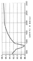
本発明を完成するに至った研究において、磨きアルミニウム反射体の熱放射特性を解析した。その結果を図1に示す。図1のデータによれば、磨きアルミニウムの反射率は約500〜約1000nmの波長でかなり低下するが、この波長範囲には慣用石英ハロゲンランプから放射される赤外線の比較的短い波長が含まれる。熱放射は一般に約780〜約1×10⁶nmの赤外線域内にあるのに対し、石英ハロゲンランプで放射される電磁波放射には可視放射(約380〜約780nm)と熱放射が含まれる。その結果、磨きアルミニウムの反射率は赤外線スペクトルの低波長端近くの熱放射に対して比較的低く、そのため超合金試料をハロゲンランプで加熱しようとするときの放射加熱の量が減る。
【0012】
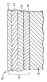
図2は、石英ハロゲンランプ(図示せず)のような熱放射用熱源の発する赤外線の反射を促進するため本発明で用いる反射体10の断面図である。反射体10はアルミニウム基材12を含むが、これは反射体10のベース構造体全体をなしていてもよいし、或いは反射体10のコーティング領域に限定されていてもよい。セラミックコーティング系14はアルミニウム基材12の表面に堆積したものとして示した。コーティング系14(特定の尺度で示したものではない)は4層のセラミック材料16,18,20,22からなるものとして示したが、これらの層については後で対をなす層16/18及び20/22として説明する。対をなす層を幾つ用いようと本発明の技術的範囲に属する。複数の対をなす層を用いることの重要性は、問題とする波長に対して透明であるが、反射体10で反射すべき波長の位相増強を達成するような屈折率の異なる2種類の材料の光学的構造干渉効果に基づく。当業者には自明であろうが、位相増強は対をなす層16/18,20/22の各々が異なる屈折率をもち、放射源に最も近い層(例えば、対をなす層16/18の層18、及び対をなす層20/22の層22)が比較的高い屈折率を有することが必要とされる。加えて、所定の対をなす層は、下記の1/4波長方程式に従って、反射すべき波長及びそれぞれの屈折率に基づく異なる厚さを有するのが好ましい。
【0013】
t=λ/4n
ただし、tはコーティング層の所要厚さ(nm)、λは問題とする波長(nm)、nはコーティング層材料の屈折率である。
【0014】
性能(反射率)と処理・費用要件とのバランスがよいので、図2に示す4層コーティング系14が好ましいが、対をなす層を追加することで望ましい光学的効果を高めることができる。層16,18,20,22に対する好適なセラミック材料には、耐火フッ化物、並びにシリカ(SiO2)、アルミナ(Al2O3)、チタニア(TiO2)、タンタラ(Ta2O5)、ジルコニア(ZiO2)、トリア(ThO2)及び酸化ニオブ(Nb2O5)等の金属酸化物があるが、他の酸化物も使用できる。これらの材料は、本発明の目的からすると、高屈折率又は低屈折率材料と分類することができる。例えば、スパッタリング成膜した耐火フッ化物、シリカ及びアルミナは概して約1.25〜約1.7の範囲の比較的低い屈折率を有し、他方、チタニア、タンタラ、ジルコニア及び酸化ニオブは概して約2〜約2.3の範囲内の比較的高い屈折率を有する。耐火性が高いので酸化物がコーティング系14の層16,18,20,22の好ましい材料であるが、1500゜F以上の温度での熱安定性及び問題とする波長での透明性の要件に適合し、コーティング系14に求められる反射率と両立し得る屈折率をもたらすものであれば、その他の材料も使用することができる。
【0015】
上述の1/4波長方程式によれば、コーティング系14の好適な厚さは、使用材料及びコーティング系14を形成する層の数に依存する。同じくこの方程式から、低屈折率のコーティング層(例えば16,20)は高屈折率のコーティング層(例えば18,22)よりも厚い。さらに具体的には、問題とする所定の波長に対し、低屈折率層(例えば16,20)は高屈折率層よりもそれらの屈折率に反比例した係数だけ厚い。一つの例では、層16,20はシリカであり、層18,22はチタニアである。約1.5及び約2.2というシリカ及びチタニアのそれぞれの屈折率に基づき、反射すべき放射線が約700〜1300nmの波長を有する場合は、シリカ層16,20の好適な厚さは約117〜217nmであり、チタニア層18,22の好適な厚さは約80〜148nmである。このとき、コーティング系14の全厚さは約394〜734nmの範囲内にある。さらに一般的には、本発明のコーティング系14の全厚さは約100〜約5000nmであり、好ましい厚さは約480nmである。
【0016】
実際に、慣用反射体の磨きスパッタリング成膜アルミニウムコーティング上に、図2に示したのと同様のコーティング系をスパッタリング成膜した。本発明を完成するに至った研究において、図1のデータを得るのに用いた試験と同じ試験を、磨きスパッタリング成膜アルミニウム表面に4層セラミック層をコーティングした反射体について行った。この4層セラミックの第1層と第3層(それぞれ図2の層16,18)はシリカであり、第2層と第4層(それぞれ図2の層20,222)はチタニアであった。第1及び第3(シリカ)層の厚さはそれぞれ約141nm及び156nmで、第2及び第4(チタニア)層の厚さはそれぞれ約97nm及び87nmであり、全皮膜厚さは約481nmであった。図3に示す通り、本発明のコート反射体は、石英ハロゲンランプの白色光を当てたとき、約700〜約1250nmの電磁波波長に対して90%を超える反射率を示し、約750〜約1200nmの波長では95%を超える反射率を示した。約700〜約1300nmの波長域で、反射体の平均反射率は約95.7%であった。図3と図1の比較から、同一条件の下で評価すると、従来技術の無コート反射体に比べ本発明のコート反射体の反射率が改善されていることが分かる。その結果、本発明のコーティング系は、約500nmから約1000nmの波長域での磨きアルミニウムの不十分な反射率を補うものであった。
【0017】
図4に本発明のコート反射体を従来技術の無コート反射体とさらに比較した結果をみることができる。この図は、従来の無被覆磨きアルミニウム反射体と、上述の4層セラミックコーティングでコーティングした磨きアルミニウム反射体とを、パワー吸収(単位:BTU/(ft2hrμm))について比較したものである。同一試験条件下では、本発明のコート反射体は、約0.6及び1.4マイクロメートル(600及び1400nm)のピーク波長間でパワー吸収の顕著な低下を示した。対照的に、従来技術の無コート反射体は約1.0マイクロメートル(約1000nm)でピーク吸収を示した。このピーク吸収の値は同一波長におけるコート反射体の吸収よりも約9倍大きい。試験波長域で、無コート反射体は本発明のコート反射体よりも約96600BTU/(ft2hr)ものパワーを余計に吸収した。
【0018】
本発明に従ってコーティングした反射体の反射率の向上によって、石英ハロゲンランプ(又は他の好適な熱放射発生ランプ)を、同じランプを従来技術の無コートアルミニウム反射体と共に用いたときと同じ加熱効果を、もっと低い入力電圧で用いて達成することができる。従って、本発明の格別の利点は、反射体性能の向上の結果、溶接前の超合金物品の加熱が改善され、超合金部品をさらに急速に及び/又はさらに高い温度に加熱できることである。本発明のコート反射体のもう一つの利点は、比較的低い入力電圧を用いて所望の加熱速度を達成でき、過剰電圧レベルの使用によってランプ寿命を短くしていた従来技術と比べてランプ寿命を長くすることができることである。最後に、本発明のコーティング系14は、ランプ入力の調節によって、物品の温度制御能力を高める。例えば、ランプをフル出力付近で用いる一方で物品を回転することでランプに露光される表面積が比較的少なくなる場合、ランプ出力をさらに高めて物品温度を維持するための出力を追加することができないので、冷却が生じてしまう。しかし、本発明では、同等の温度とするのにランプをフル出力よりも十分に低い値で操作することができるので、物品の回転を補償するため出力を追加することができる。
【0019】
熱放射用熱源の反射体用のコーティングについて説明したが、本発明のコーティング系14は、その中で超合金の溶接作業が行われるエンクロージャの内側にも適用できる。このコーティング系14のもう一つの利点は、付着防止コーティングとして作用し、溶接時に反射体及びエンクロージャの表面に生じる堆積物の除去が比較的容易になることである。
【0020】
以上、本発明を好ましい実施形態に関して説明したが、他の好適なコーティング及び基材材料に置換したり、或いはコーティング層の成膜に様々な方法を利用することによって、当業者が他の様々な形態を採用できることは自明である。従って、本発明の技術的範囲は特許請求の範囲によってのみ規定される。
【図面の簡単な説明】
【図1】 従来技術のアルミニウム反射体について、反射率を波長に対してプロットしたグラフである。
【図2】 本発明の反射コーティングを備えた石英ハロゲンランプ反射体の一部の断面図である。
【図3】 図2のコートアルミニウム反射体について、反射率を波長に対してプロットしたグラフである。
【図4】 従来技術のアルミニウム反射体及び図2のコートアルミニウム反射体について、波長に対してパワー吸収をプロットしたものを対比したグラフである。
【符号の説明】
10 反射体
12 アルミニウム基材
14 セラミックコーティング系[0001]
[Field of the Invention]
The present invention relates to an apparatus and method for welding superalloy components. More specifically, the present invention relates to a reflective coating for increasing the reflectivity of a reflector near a lamp that is used to preheat and keep the superalloy component at a high temperature during welding operations.
[0002]
TECHNICAL BACKGROUND OF THE INVENTION
Heat-resistant cobalt-base and nickel-base superalloys are widely used in the manufacture of parts such as gas turbine engine combustors, turbine vanes and blades. Although heat resistant superalloy parts are often made by casting, there are situations where it is preferable or necessary to produce superalloy parts by welding. For example, complex shaped parts such as turbine midframes and shroud support rings can be manufactured relatively easily by welding separate castings. Therefore, it is often more practical and cost effective to manufacture a complex part by welding than casting it as an integral part.
[0003]
In addition to these, welding is widely used in the repair of blade tips and methods for repairing cracks and other surface discontinuities in superalloy parts due to thermal cycling or foreign object impact. Because the cost of parts made of refractory cobalt-base and nickel-base superalloys is relatively high, it is usually desirable to repair / repair rather than replace parts when they are worn or damaged.
[0004]
In order to increase the welding yield, conventionally, superalloy parts are preheated before welding and continuously heated during welding. For this purpose, preheating temperatures in excess of about 1500 ° F. (815 ° C.), often preheating temperatures in excess of 1700 ° F. (925 ° C.) may be used. Such superalloy components are often heated and welded using a welding technique such as tungsten inert gas (TIG) welding or laser welding in an enclosure containing a controlled atmosphere (eg, inert gas). To be implemented. Preheating is usually carried out by induction heating or using a lamp (especially a quartz halogen lamp). Lamps often include a polished aluminum reflector that heats the target superalloy component with thermal radiation and thus reflects the thermal radiation toward the components to be welded in the enclosure. A lamp used as a heat source may be used at an input voltage higher than the rated voltage of the lamp. For example, a lamp having a rated voltage of 90 to 100V may be used at 105 to 110V. As a result, lamp life is dramatically reduced and component temperature control is not optimal.
[0005]
Therefore, it would be desirable if the heating efficiency of the welding apparatus used for the welding operation of the superalloy article can be improved. In particular, it would be desirable to be able to heat superalloy articles more rapidly and efficiently with such equipment while maintaining temperature control and extending the life of the equipment used to heat the article.
[0006]
SUMMARY OF THE INVENTION
The present invention generally provides a heating apparatus and method for welding superalloy articles. In a preferred embodiment, such an apparatus and method includes welding the superalloy article in an enclosure equipped with a thermal radiation generator that preheats the superalloy article to a temperature of 1500 ° F. or higher prior to welding. More specifically, the present invention provides a heat reflective coating on a reflective member disposed proximate to the thermal radiation generator to reflect thermal radiation emitted by the thermal radiation generator into the enclosure. The thermal radiation generator is then activated to heat the superalloy article to a suitable temperature (eg, 1500 ° F. or higher), after which a welding operation is performed on the superalloy article.
[0007]
In the present invention, the heat-reflective coating comprises at least one pair of reflective layers, each layer being formed of a material that is substantially transparent to electromagnetic wave wavelengths between 500 and 3000 nanometers (nm). In addition, the material of the outermost layer of the pair of reflective layers has a higher refractive index than the material of the other layer of the pair. The coating of the present invention has a reflectance of conventional aluminum reflectors for electromagnetic wave wavelengths of about 700 to about 1250 nm (this wavelength range is in the spectral range of thermal radiation (near infrared) emitted by a thermal radiation lamp such as a quartz halogen lamp). Has been shown to increase to over 90%. Accordingly, even when a quartz halogen lamp is used at a relatively low input power, the superalloy article can be sufficiently heated to perform a desired welding operation (for example, TIG welding or laser welding for assembling or repairing the article) on the article. it can. As a result, the apparatus of the present invention can heat the superalloy article to be welded relatively quickly and efficiently with a predetermined input power. The apparatus can also be operated to increase lamp life by reducing the power required to reach the desired temperature when preheating and welding the article. Finally, the present invention increases the temperature control capability of the article by adjusting the lamp input.
[0008]
Other objects and advantages of this invention will be better appreciated from the following detailed description.
[0009]
[Preferred Embodiment]
The present invention relates generally to superalloy articles that need to be welded during manufacture and / or repair. While the advantages of the present invention are described with respect to gas turbine engine components, the present invention is applicable to a variety of applications for heating articles with devices that emit thermal radiation.
[0010]
Enclosures for performing welding operations such as TIG welding and laser welding in a controlled atmosphere are known, and heat radiation heating devices including various lamp designs are also known. Traditionally, lamps such as quartz halogen lamps have been equipped with polished aluminum reflectors to facilitate the reflection of heat (thermal radiation) to the target superalloy. Aluminum reflectors known in the art are made of aluminum or have an aluminum coating. The latter example is an aluminum coating deposited by sputtering, which can be protected with a corrosion resistant coating to prevent the formation of aluminum oxide (alumina), which can reduce the reflectivity of the aluminum.
[0011]
In the study that led to the completion of the present invention, the thermal radiation properties of polished aluminum reflectors were analyzed. The result is shown in FIG. According to the data in FIG. 1, the reflectivity of polished aluminum decreases significantly at wavelengths of about 500 to about 1000 nm, but this wavelength range includes the relatively short wavelengths of infrared radiation emitted from conventional quartz halogen lamps. Thermal radiation is generally in the infrared region of about 780 to about 1 × 10 6 nm, whereas electromagnetic radiation emitted by quartz halogen lamps includes visible radiation (about 380 to about 780 nm) and thermal radiation. As a result, the reflectivity of polished aluminum is relatively low for thermal radiation near the lower wavelength end of the infrared spectrum, thus reducing the amount of radiant heating when attempting to heat a superalloy sample with a halogen lamp.
[0012]
FIG. 2 is a cross-sectional view of the
[0013]
t = λ / 4n
Where t is the required thickness (nm) of the coating layer, λ is the wavelength of interest (nm), and n is the refractive index of the coating layer material.
[0014]
The four-
[0015]
According to the ¼ wavelength equation described above, the preferred thickness of the
[0016]
In practice, a conventional reflector was sputter-deposited on the aluminum coating. A coating system similar to that shown in FIG. In the study that led to the completion of the present invention, the same test used to obtain the data of FIG. 1 was performed on a reflector having a four-layer ceramic layer coated on a polished and sputtered aluminum surface. The first and third layers (
[0017]
FIG. 4 shows the result of further comparing the coated reflector of the present invention with the uncoated reflector of the prior art. This figure compares a conventional uncoated polished aluminum reflector with a polished aluminum reflector coated with the above four-layer ceramic coating in terms of power absorption (unit: BTU / (ft 2 hr μm)). Under the same test conditions, the coated reflector of the present invention showed a significant decrease in power absorption between peak wavelengths of about 0.6 and 1.4 micrometers (600 and 1400 nm). In contrast, prior art uncoated reflectors showed peak absorption at about 1.0 micrometers (about 1000 nm). This peak absorption value is about nine times larger than the absorption of the coated reflector at the same wavelength. In the test wavelength range, the uncoated reflector absorbed an extra power of about 96600 BTU / (ft 2 hr) more than the coated reflector of the present invention.
[0018]
By improving the reflectivity of the reflector coated according to the present invention, quartz halogen lamps (or other suitable thermal radiation generating lamps) can have the same heating effect as when the same lamp is used with a prior art uncoated aluminum reflector. Can be achieved using lower input voltages. Thus, a particular advantage of the present invention is that the improved reflector performance results in improved heating of the superalloy article prior to welding, allowing the superalloy component to be heated more rapidly and / or to higher temperatures. Another advantage of the coated reflector of the present invention is that a relatively low input voltage can be used to achieve the desired heating rate and lamp life is reduced compared to the prior art where lamp life is shortened through the use of excessive voltage levels. It can be long. Finally, the
[0019]
Although a coating for a reflector of a heat radiation heat source has been described, the
[0020]
While the present invention has been described in terms of a preferred embodiment, those skilled in the art will recognize that other suitable coatings and substrate materials can be substituted or various other methods can be used to form a coating layer by those skilled in the art. It is obvious that the form can be adopted. Accordingly, the technical scope of the present invention is defined only by the claims.
[Brief description of the drawings]
FIG. 1 is a graph plotting reflectivity against wavelength for a prior art aluminum reflector.
FIG. 2 is a cross-sectional view of a part of a quartz halogen lamp reflector provided with the reflective coating of the present invention.
FIG. 3 is a graph plotting reflectance with respect to wavelength for the coated aluminum reflector of FIG. 2;
4 is a graph comparing power absorption versus wavelength plots for a prior art aluminum reflector and the coated aluminum reflector of FIG.
[Explanation of symbols]
10
Claims (10)
エンクロージャと、
上記エンクロージャ内部を加熱するための石英ハロゲンランプと、
上記石英ハロゲンランプの発する熱放射を上記エンクロージャ内に反射するため上記石英ハロゲンランプに近接して配置された反射部材(10)であって、磨きアルミニウムでできた表面領域(12)を有する反射部材(10)と、
反射部材(10)の表面領域(12)を被覆しかつ接している熱反射コーティング(14)と
を含んでおり、上記コーティング(14)が、500〜3000ナノメートルの電磁波波長に対して透明な金属酸化物でできた隣り合う少なくとも1対の層(16/18,20/22)を含んでなり、上記の対をなす層(16/18,20/22)の最外層(18,22)が該対をなす層(16/18,20/22)の最内層(16,20)よりも高い屈折率を有していて、最内層(16,20)が最外層(18,22)よりも最内層の屈折率と最外層の屈折率との比に反比例した係数だけ厚く構成され、もってエンクロージャ内に入れられた超合金物品を816℃(1500°F)以上の温度に加熱するように上記石英ハロゲンランプを操作できる、加熱装置。A heating device,
An enclosure,
A quartz halogen lamp for heating the inside of the enclosure;
A reflective member (10) disposed proximate to the quartz halogen lamp for reflecting thermal radiation emitted by the quartz halogen lamp into the enclosure, the reflective member having a surface region (12) made of polished aluminum (10) and
And a heat reflective coating (14) covering and in contact with the surface region (12) of the reflective member (10), wherein the coating (14) is transparent to electromagnetic wavelengths of 500 to 3000 nanometers. The outermost layer (18, 22) of the paired layers (16/18, 20/22) comprising at least one pair of adjacent layers (16/18, 20/22) made of metal oxide Has a higher refractive index than the innermost layer (16, 20) of the paired layers (16/18, 20/22), and the innermost layer (16, 20) is more than the outermost layer (18, 22). So that the superalloy article having a thickness inversely proportional to the ratio between the refractive index of the innermost layer and the refractive index of the outermost layer is heated to a temperature of 816 ° C. (1500 ° F.) or higher. Can operate the quartz halogen lamp , The heating device.
請求項1乃至請求項6のいずれか1項記載の加熱装置を準備し、
超合金物品を前記エンクロージャ内に配置し、
前記石英ハロゲンランプを作動して超合金物品を816℃(1500°F)以上に加熱し、次いで
超合金物品で溶接作業を実施する
ことを含む方法。A superalloy welding method,
A heating device according to any one of claims 1 to 6 is prepared,
Placing a superalloy article in the enclosure;
Activating the quartz halogen lamp to heat the superalloy article to 816 ° C. (1500 ° F.) or higher and then performing a welding operation on the superalloy article.
Applications Claiming Priority (2)
| Application Number | Priority Date | Filing Date | Title |
|---|---|---|---|
| US09/224,891 US6054687A (en) | 1998-12-31 | 1998-12-31 | Heating apparatus for a welding operation and method therefor |
| US09/224891 | 1998-12-31 |
Publications (3)
| Publication Number | Publication Date |
|---|---|
| JP2000225489A JP2000225489A (en) | 2000-08-15 |
| JP2000225489A5 JP2000225489A5 (en) | 2007-02-22 |
| JP4885343B2 true JP4885343B2 (en) | 2012-02-29 |
Family
ID=22842649
Family Applications (1)
| Application Number | Title | Priority Date | Filing Date |
|---|---|---|---|
| JP36887799A Expired - Fee Related JP4885343B2 (en) | 1998-12-31 | 1999-12-27 | Heating apparatus and method for welding work |
Country Status (7)
| Country | Link |
|---|---|
| US (1) | US6054687A (en) |
| EP (1) | EP1016488B1 (en) |
| JP (1) | JP4885343B2 (en) |
| BR (1) | BR9907444A (en) |
| DE (1) | DE69917876T2 (en) |
| SG (1) | SG82055A1 (en) |
| TR (1) | TR199903312A2 (en) |
Families Citing this family (15)
| Publication number | Priority date | Publication date | Assignee | Title |
|---|---|---|---|---|
| US6333484B1 (en) * | 2000-03-17 | 2001-12-25 | Chromalloy Gas Turbine Corporation | Welding superalloy articles |
| JP3859072B2 (en) * | 2001-03-08 | 2006-12-20 | 信越半導体株式会社 | Heat ray reflective material and heating device using the same |
| US6839507B2 (en) * | 2002-10-07 | 2005-01-04 | Applied Materials, Inc. | Black reflector plate |
| US7137544B2 (en) * | 2002-12-13 | 2006-11-21 | General Electric Company | Apparatus and method for performing welding at elevated temperature |
| US6927361B2 (en) * | 2003-09-04 | 2005-08-09 | Thomas Joseph Kelly | Surface oxide weld penetration enhancement method and article |
| NL1026156C2 (en) * | 2004-05-10 | 2005-11-11 | Euromedley B V | Ceramic reflector. |
| US20060219758A1 (en) * | 2005-03-29 | 2006-10-05 | Siemens Westinghouse Power Corporation | Welding of gamma'-strengthened superalloys |
| US7094988B1 (en) | 2005-04-18 | 2006-08-22 | Honeywell International, Inc. | Laser welding heat treat process |
| US20060231535A1 (en) * | 2005-04-19 | 2006-10-19 | Fuesting Timothy P | Method of welding a gamma-prime precipitate strengthened material |
| WO2006119791A1 (en) * | 2005-05-10 | 2006-11-16 | Van Den Bergh Paulus Marinus H | Ceramic reflector |
| DE102006029252A1 (en) * | 2006-06-26 | 2007-12-27 | Advanced Photonics Technologies Ag | Plant for machining a workpiece with UV, NIR or IR radiation |
| US20080116245A1 (en) * | 2006-11-17 | 2008-05-22 | General Electric Company | Lamp-based swet welding apparatus |
| US20080164301A1 (en) * | 2007-01-10 | 2008-07-10 | General Electric Company | High temperature laser welding |
| US20090026173A1 (en) * | 2007-07-26 | 2009-01-29 | General Electric Company | Method and apparatus for welding an article |
| CN102072454A (en) * | 2011-03-02 | 2011-05-25 | 查燕旻 | High reflectivity lampshade |
Family Cites Families (20)
| Publication number | Priority date | Publication date | Assignee | Title |
|---|---|---|---|---|
| NL84100C (en) * | 1950-06-23 | 1957-02-15 | ||
| GB1236103A (en) * | 1967-08-29 | 1971-06-23 | Messer Griesheim Gmbh | An electric apparatus for heating, melting, welding, soldering and cutting workpieces by focusing radiation from a source thereof at a working point or line on the workpiece |
| US3718497A (en) * | 1970-11-19 | 1973-02-27 | Gen Motors Corp | Heater coil support |
| JPS52700B2 (en) * | 1971-11-10 | 1977-01-10 | ||
| JPS5833101B2 (en) * | 1978-11-13 | 1983-07-18 | 横浜機工株式会社 | heat resistant reflector |
| JPS5833099B2 (en) * | 1978-11-13 | 1983-07-18 | 日本発条株式会社 | Multilayer coating reflector |
| JPS5628487A (en) * | 1979-08-14 | 1981-03-20 | Tokyo Shibaura Electric Co | Heat reflecting plate |
| JPS5958753A (en) * | 1982-09-28 | 1984-04-04 | 株式会社東芝 | Incandescent bulb |
| JPS60195502A (en) * | 1984-03-19 | 1985-10-04 | Canon Inc | Rotary polyhedral mirror made of metal |
| JPS6172389A (en) * | 1984-09-17 | 1986-04-14 | 株式会社東芝 | Security thread detector |
| JPS61219004A (en) * | 1985-03-25 | 1986-09-29 | Canon Inc | Multilayer film reflecting mirror |
| CA2017471C (en) * | 1989-07-19 | 2000-10-24 | Matthew Eric Krisl | Optical interference coatings and lamps using same |
| DE4141927C2 (en) * | 1991-12-19 | 1995-06-14 | Mtu Maintenance Gmbh | Method and device for welding workpieces |
| US5412274A (en) * | 1992-12-17 | 1995-05-02 | General Electric Company | Diffusely reflecting optical interference filters and articles including lamps reflectors and lenses |
| JPH07333542A (en) * | 1994-06-09 | 1995-12-22 | Matsushita Electric Ind Co Ltd | Reflection mirror and its production |
| DE4432315A1 (en) * | 1994-09-12 | 1996-03-14 | Patent Treuhand Ges Fuer Elektrische Gluehlampen Mbh | Mercury vapor short arc lamp |
| JPH08212819A (en) * | 1995-10-06 | 1996-08-20 | Toshiba Lighting & Technol Corp | Lighting fitting |
| EP0816875A1 (en) * | 1996-06-28 | 1998-01-07 | Alusuisse Technology & Management AG | Reflector with reflection enhancing coating |
| US5905269A (en) * | 1997-05-23 | 1999-05-18 | General Electric Company | Enhanced infrared energy reflecting composition and method of manufacture |
| US5898180A (en) * | 1997-05-23 | 1999-04-27 | General Electric Company | Infrared energy reflecting composition and method of manufacture |
-
1998
- 1998-12-31 US US09/224,891 patent/US6054687A/en not_active Expired - Lifetime
-
1999
- 1999-12-17 SG SG9906441A patent/SG82055A1/en unknown
- 1999-12-22 EP EP99310447A patent/EP1016488B1/en not_active Expired - Lifetime
- 1999-12-22 DE DE69917876T patent/DE69917876T2/en not_active Expired - Lifetime
- 1999-12-27 JP JP36887799A patent/JP4885343B2/en not_active Expired - Fee Related
- 1999-12-29 TR TR1999/03312A patent/TR199903312A2/en unknown
- 1999-12-30 BR BR9907444-3A patent/BR9907444A/en not_active IP Right Cessation
Also Published As
| Publication number | Publication date |
|---|---|
| EP1016488B1 (en) | 2004-06-09 |
| BR9907444A (en) | 2001-01-16 |
| DE69917876T2 (en) | 2005-06-09 |
| EP1016488A2 (en) | 2000-07-05 |
| EP1016488A3 (en) | 2001-12-05 |
| DE69917876D1 (en) | 2004-07-15 |
| JP2000225489A (en) | 2000-08-15 |
| SG82055A1 (en) | 2001-07-24 |
| US6054687A (en) | 2000-04-25 |
| TR199903312A2 (en) | 2000-07-21 |
Similar Documents
| Publication | Publication Date | Title |
|---|---|---|
| JP4885343B2 (en) | Heating apparatus and method for welding work | |
| JP2629693B2 (en) | Excimer laser mirror | |
| US5851679A (en) | Multilayer dielectric stack coated part for contact with combustion gases | |
| EP1880578A1 (en) | A reflector for an infrared radiating element | |
| JPH04295801A (en) | Dichroic coating having controlled heat reflection | |
| JPS5865403A (en) | Optical coating suitable for high temperature application | |
| JP4896287B2 (en) | Coating to reduce the operating temperature of chamber parts in coating equipment | |
| US9696467B2 (en) | UV and DUV expanded cold mirrors | |
| MXPA99012028A (en) | Heating apparatus for a welding operation and method therefor | |
| JP4185195B2 (en) | Optical article and light bulb with infrared reflective coating | |
| EP1180639A2 (en) | Increased life reflector lamps | |
| JPS59148654A (en) | Heat wave shielding member | |
| Rainer et al. | Review of UV laser damage measurements at Lawrence Livermore National Laboratory | |
| JP3102959B2 (en) | High durability thin film | |
| JP3153050B2 (en) | Incandescent light bulb | |
| JP2714397B2 (en) | Non-heat reflecting mirror | |
| JP3054663B2 (en) | Multilayer reflector | |
| JP3110131B2 (en) | High durability thin film | |
| JPH0529081B2 (en) | ||
| JPS62240903A (en) | Multi-layered reflection mirror | |
| JPS62165601A (en) | Reflecting mirror for laser beam | |
| CN116774490A (en) | Optical film with adjustable all-solid transmittance and preparation method thereof | |
| JP2629693C (en) | ||
| JPH0239107A (en) | Multilayered interference film | |
| Mellor | Optical Coatings For High Performance Lighting Applications |
Legal Events
| Date | Code | Title | Description |
|---|---|---|---|
| A521 | Written amendment |
Free format text: JAPANESE INTERMEDIATE CODE: A523 Effective date: 20061227 |
|
| A621 | Written request for application examination |
Free format text: JAPANESE INTERMEDIATE CODE: A621 Effective date: 20061227 |
|
| RD02 | Notification of acceptance of power of attorney |
Free format text: JAPANESE INTERMEDIATE CODE: A7422 Effective date: 20090727 |
|
| RD04 | Notification of resignation of power of attorney |
Free format text: JAPANESE INTERMEDIATE CODE: A7424 Effective date: 20090727 |
|
| A131 | Notification of reasons for refusal |
Free format text: JAPANESE INTERMEDIATE CODE: A131 Effective date: 20091117 |
|
| A601 | Written request for extension of time |
Free format text: JAPANESE INTERMEDIATE CODE: A601 Effective date: 20100216 |
|
| A602 | Written permission of extension of time |
Free format text: JAPANESE INTERMEDIATE CODE: A602 Effective date: 20100219 |
|
| A601 | Written request for extension of time |
Free format text: JAPANESE INTERMEDIATE CODE: A601 Effective date: 20100317 |
|
| A602 | Written permission of extension of time |
Free format text: JAPANESE INTERMEDIATE CODE: A602 Effective date: 20100323 |
|
| A601 | Written request for extension of time |
Free format text: JAPANESE INTERMEDIATE CODE: A601 Effective date: 20100416 |
|
| A602 | Written permission of extension of time |
Free format text: JAPANESE INTERMEDIATE CODE: A602 Effective date: 20100421 |
|
| A521 | Written amendment |
Free format text: JAPANESE INTERMEDIATE CODE: A523 Effective date: 20100517 |
|
| A131 | Notification of reasons for refusal |
Free format text: JAPANESE INTERMEDIATE CODE: A131 Effective date: 20100831 |
|
| A601 | Written request for extension of time |
Free format text: JAPANESE INTERMEDIATE CODE: A601 Effective date: 20101130 |
|
| A602 | Written permission of extension of time |
Free format text: JAPANESE INTERMEDIATE CODE: A602 Effective date: 20101203 |
|
| A521 | Written amendment |
Free format text: JAPANESE INTERMEDIATE CODE: A523 Effective date: 20110225 |
|
| RD03 | Notification of appointment of power of attorney |
Free format text: JAPANESE INTERMEDIATE CODE: A7423 Effective date: 20110526 |
|
| A131 | Notification of reasons for refusal |
Free format text: JAPANESE INTERMEDIATE CODE: A131 Effective date: 20110531 |
|
| A521 | Written amendment |
Free format text: JAPANESE INTERMEDIATE CODE: A523 Effective date: 20110606 |
|
| TRDD | Decision of grant or rejection written | ||
| A01 | Written decision to grant a patent or to grant a registration (utility model) |
Free format text: JAPANESE INTERMEDIATE CODE: A01 Effective date: 20111108 |
|
| A01 | Written decision to grant a patent or to grant a registration (utility model) |
Free format text: JAPANESE INTERMEDIATE CODE: A01 |
|
| A61 | First payment of annual fees (during grant procedure) |
Free format text: JAPANESE INTERMEDIATE CODE: A61 Effective date: 20111208 |
|
| FPAY | Renewal fee payment (event date is renewal date of database) |
Free format text: PAYMENT UNTIL: 20141216 Year of fee payment: 3 |
|
| R150 | Certificate of patent or registration of utility model |
Free format text: JAPANESE INTERMEDIATE CODE: R150 |
|
| LAPS | Cancellation because of no payment of annual fees |