JP4882026B2 - COMMUNICATION SYSTEM AND COMMUNICATION CONTROL DEVICE - Google Patents
COMMUNICATION SYSTEM AND COMMUNICATION CONTROL DEVICE Download PDFInfo
- Publication number
- JP4882026B2 JP4882026B2 JP2010544041A JP2010544041A JP4882026B2 JP 4882026 B2 JP4882026 B2 JP 4882026B2 JP 2010544041 A JP2010544041 A JP 2010544041A JP 2010544041 A JP2010544041 A JP 2010544041A JP 4882026 B2 JP4882026 B2 JP 4882026B2
- Authority
- JP
- Japan
- Prior art keywords
- control device
- plane
- information
- route
- packet
- Prior art date
- Legal status (The legal status is an assumption and is not a legal conclusion. Google has not performed a legal analysis and makes no representation as to the accuracy of the status listed.)
- Expired - Fee Related
Links
- 238000004891 communication Methods 0.000 title claims description 95
- 238000012545 processing Methods 0.000 claims description 67
- 238000012546 transfer Methods 0.000 claims description 38
- 238000000034 method Methods 0.000 claims description 27
- 238000000926 separation method Methods 0.000 claims description 19
- 230000008569 process Effects 0.000 claims description 17
- 238000012790 confirmation Methods 0.000 claims description 12
- 230000005540 biological transmission Effects 0.000 claims description 11
- 230000004083 survival effect Effects 0.000 claims description 8
- 229920006235 chlorinated polyethylene elastomer Polymers 0.000 description 14
- 238000010586 diagram Methods 0.000 description 12
- 230000008859 change Effects 0.000 description 9
- 230000006870 function Effects 0.000 description 7
- 238000012508 change request Methods 0.000 description 2
- 230000004931 aggregating effect Effects 0.000 description 1
- 238000000136 cloud-point extraction Methods 0.000 description 1
- 230000001404 mediated effect Effects 0.000 description 1
- 230000004044 response Effects 0.000 description 1
- 230000001960 triggered effect Effects 0.000 description 1
Images


Classifications
-
- H—ELECTRICITY
- H04—ELECTRIC COMMUNICATION TECHNIQUE
- H04L—TRANSMISSION OF DIGITAL INFORMATION, e.g. TELEGRAPHIC COMMUNICATION
- H04L45/00—Routing or path finding of packets in data switching networks
- H04L45/74—Address processing for routing
- H04L45/745—Address table lookup; Address filtering
-
- H—ELECTRICITY
- H04—ELECTRIC COMMUNICATION TECHNIQUE
- H04L—TRANSMISSION OF DIGITAL INFORMATION, e.g. TELEGRAPHIC COMMUNICATION
- H04L45/00—Routing or path finding of packets in data switching networks
-
- H—ELECTRICITY
- H04—ELECTRIC COMMUNICATION TECHNIQUE
- H04L—TRANSMISSION OF DIGITAL INFORMATION, e.g. TELEGRAPHIC COMMUNICATION
- H04L45/00—Routing or path finding of packets in data switching networks
- H04L45/56—Routing software
Landscapes
- Engineering & Computer Science (AREA)
- Computer Networks & Wireless Communication (AREA)
- Signal Processing (AREA)
- Data Exchanges In Wide-Area Networks (AREA)
Description
本発明は、通信システム及び通信制御装置に係り、特に、ルーティングプロトコルのような制御メッセージを処理するCプレーンと、ユーザデータパケットを転送処理するUプレーンが分離した装置で構成される通信システム及び通信制御装置に関する。 The present invention relates to a communication system and a communication control device, and in particular, a communication system and communication configured by a device in which a C plane for processing control messages such as a routing protocol and a U plane for transferring user data packets are separated. The present invention relates to a control device.
ルータをControl Element(CE、制御部)とForwarding Element(FE、データ転送部)に分離したモデルを前提として、CEとFE間の制御用プロトコルを規定するという取組みがIETF(Internet Engineering Task Force)のForCES(Forwarding and Control Element Separation)WG(Working Group)で行なわれている。
また、CEとFEの分離モデルと同様に、制御部とデータ転送部を装置分離したIPパケット通信システムについて開示されたものがある(例えば、特許文献1参照)。
制御部のことをCプレーン、データ転送部のことをUプレーンまたはDプレーンと呼ぶことも多いが、Cプレーン制御装置とUプレーン制御装置の接続関係を制御する方式に関して開示されたものがある(例えば、特許文献2参照)。
なお、Cプレーンとは、Control Planeを意味しており、装置間でやり取りする制御メッセージのデータが通るリンクのことをいう。また、Uプレーンとは、User data Planeを意味しており、実際にユーザの端末間で送受信される様々なコンテンツデータが通るリンクのことをいう。
インターネットを含む従来のネットワークシステムを構成しているルータやスイッチは、Cプレーン制御機能とUプレーン制御機能が一体となった装置構成を採っている。従来型のネットワークシステムでは、Cプレーンのメッセージトラフィックが増大した場合にも、Uプレーンのメッセージトラフィックが増大した場合にも、ルータやスイッチといった単位での増設が必要であった。Based on the premise of a model in which a router is separated into a control element (CE, control unit) and a forwarding element (FE, data transfer unit), an effort to define a control protocol between the CE and the FE is an IETF (Internet Engineering Task Force). ForCES (Forwarding and Control Element Separation) WG (Working Group).
In addition, as in the CE and FE separation model, there has been disclosed an IP packet communication system in which a control unit and a data transfer unit are separated (see, for example, Patent Document 1).
The control unit is often called a C plane, and the data transfer unit is often called a U plane or a D plane. However, there has been disclosed a method for controlling a connection relationship between a C plane control device and a U plane control device ( For example, see Patent Document 2).
The C plane means a control plane, which is a link through which control message data exchanged between apparatuses passes. The U plane means User data Plane, which is a link through which various content data actually transmitted and received between user terminals passes.
The routers and switches constituting the conventional network system including the Internet adopt a device configuration in which the C plane control function and the U plane control function are integrated. In the conventional network system, when the C-plane message traffic increases or when the U-plane message traffic increases, it is necessary to add a unit such as a router or a switch.
それに対して上記のようなCプレーン制御機能とUプレーン制御機能を分離するアーキテクチャは、Cプレーンのメッセージトラフィックが増大した場合にはCプレーン制御装置を増設し、Uプレーンのメッセージトラフィックが増大した場合にはUプレーン制御装置を増設するといった、スケーラビリティ面での費用対効果の向上を狙いの一つとしている。
インターネットの急速な拡大は、ルータのようなノード装置がルーティングプロトコルを用いて相互に経路情報を交換するという特性が、ネットワークの自律分散的な拡張に寄与していたという一面がある。しかし一方では、ネットワーク管理という観点からは、動的に自律変動する通信経路の把握・制御が難しいという課題を抱えている。
この課題に対し、Cプレーン制御装置とUプレーン制御装置を装置分離するというC/U分離型のネットワークアーキテクチャは、Cプレーンの情報を集約することで通信経路を把握し易くすると共に、主体的な経路制御を可能にするという狙いも含んでいる。
また、Uプレーン制御装置はCプレーン制御装置から設定される経路情報に基づいてデータ転送を行い、経路情報の明示的な変更が無い限りは、既に設定されている経路情報に従ってデータ転送を続ける。このように動作することで、Cプレーンの障害がUプレーンの動作に影響を与えないようにする狙いがある。
The rapid expansion of the Internet has one aspect that node devices such as routers exchange routing information with each other using a routing protocol, which contributes to autonomously distributed expansion of the network. However, on the other hand, from the viewpoint of network management, there is a problem that it is difficult to grasp and control a communication path that dynamically changes autonomously.
In response to this problem, the C / U separation type network architecture in which the C plane control device and the U plane control device are separated from each other makes it easy to grasp the communication path by aggregating the information of the C plane. It also includes the aim of enabling route control.
Further, the U plane control device performs data transfer based on the route information set from the C plane control device, and continues data transfer according to the already set route information unless the route information is explicitly changed. By operating in this way, there is an aim to prevent the failure of the C plane from affecting the operation of the U plane.
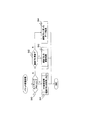
図1を参照して本発明が解決しようとする課題を説明する。図1では、CE相当のCプレーン制御装置をルーティングエンジン(RE:Routing Engine)1、FE相当のUプレーン制御装置をPE(PE:Provider Edge)2として表している。コアネットワーク6を構成するノード装置であるPE2は、ルーティングエンジン1からFIB(Forwarding Information Base)情報を受信し、ユーザデータパケットの転送は、ルーティングエンジン1から受信したFIB情報に基づいて転送処理を行う。つまり、コアネットワーク6は、CプレーンとUプレーンが分離したC/U分離型のネットワークを構成している。
このようなC/U分離型のネットワークに、ユーザネットワークであるLAN(Local Area Network)8を接続するには、コアネットワーク6側のノード装置(PE)2とユーザネットワーク側のノード装置であるCPE(Customer Premises Equipment、以下ユーザルータ、ノード装置と称することもある)3を、アクセス網7を介して接続することになる。
このときのCPEの形態としては例えば3通りの方法が考えられる。1つ目は、コアネットワーク6側のノード装置(PE)2と同様に、Uプレーン制御機能のみを有するノード装置4を用いて接続する形態である。このようなC/U分離型のCPE4では、ユーザデータパケットの転送もPE2と同様にルーティングエンジン1から受信したFIB情報に基づいて行う。A problem to be solved by the present invention will be described with reference to FIG. In FIG. 1, a C plane control device equivalent to CE is represented as a routing engine (RE) 1, and a U plane control device equivalent to FE is represented as PE (PE: Provider Edge) 2. The
In order to connect a LAN (Local Area Network) 8 that is a user network to such a C / U separation type network, a node device (PE) 2 on the
As a form of CPE at this time, for example, three methods are conceivable. The first is a form of connection using a
2つ目は、所謂L2スイッチ5を用いて接続する形態である。この場合は、従来のC/U一体型のノード装置で構成されるコアネットワークに接続するのと違いは無い。
3つ目は、従来のルータのようなC/U一体型のノード装置3を用いて接続する形態である。この場合は、接続する先のコアネットワーク6の形態が従来のC/U一体型とは異なるため、ノード装置3から見たときの隣接ピアの捉え方が異なってくる。具体的には、ノード装置3にとって、Cプレーンの隣接ピアはルーティングエンジン1となり、Uプレーンの通信における次ホップはPE2aとなる。すなわち、Uプレーンに関しては、従来型のC/U一体型のノード装置で構成されるコアネットワークに接続する場合と同様だが、Cプレーンに関して違いが出てくる。
従来のC/U一体型のコアネットワークにCPEが接続される場合は、CPE3から見たCプレーンの隣接ピアはPE2aに位置するノード装置であったため、コアネットワーク6内においてCプレーンの通信障害が発生しても、CPE3とPE2a間でのCプレーンの生存確認が取れている間は、CPE3から見れば通信障害とはならず、データ転送を止めていなかった。
しかしながら、コアネットワーク6がC/U分離型のノード装置で構成される場合には、C/U一体型のCPE3から見たCプレーンの隣接ピアはコアネットワーク6内のルーティングエンジン1となる。そのため、例えば、コアネットワーク6内におけるCプレーンの通信障害によりCPE3とルーティングエンジン1間のCプレーンの生存確認が途絶えてしまうと、CPE3は通信障害と見なしてデータ転送を止めてしまう。The second is a form of connection using a so-called
The third is a form of connection using a C / U integrated
When the CPE is connected to the conventional C / U integrated core network, since the adjacent peer of the C plane viewed from the
However, when the
Cプレーンの通信障害を引き起こした原因が、ルーティングエンジン1の障害であったり、ルーティングエンジン1とPE2aの間の区間の通信障害であった場合などは、CPE3とPE2の間、PE2同士の間の通信は有効で、ユーザネットワーク間の通信は本来は可能であるはずである。しかしながら、そのような事はCPE3では判らず、自身のCプレーン通信の結果に従って動作するため、通信の停止を避けることが出来ない。
C/U分離型のネットワークシステムを導入していく過程では、ユーザ設備として、CPE3のような従来型のルータを許容する必要が出てくる。そのときに、従来型のC/U一体型のネットワークシステムに接続する場合には問題とはならなかったコアネットワーク6側の障害が、C/U分離型のネットワークシステムに接続する場合に問題となっては、ユーザにとって受け入れ難いシステムとなってしまう。
本発明は、このような課題を解決することを目的とし、特に、C/U分離型のネットワークシステムに、C/U一体型のルータを接続する構成のネットワークにおいて、C/U分離型ネットワーク側の障害により、C/U分離型ネットワークのCプレーン制御装置から送信されるメッセージが通信障害となる場合でも、C/U一体型ルータのUプレーン通信が止まらないような通信システム及び通信制御装置を提供することを目的のひとつとする。If the cause of the communication failure in the C plane is a failure in the
In the process of introducing a C / U separation type network system, it is necessary to allow a conventional router such as CPE3 as user equipment. At that time, a failure on the
The present invention aims to solve such problems, and in particular, in a network configured to connect a C / U integrated router to a C / U separated network system, the C / U separated network side A communication system and a communication control device in which the U-plane communication of the C / U integrated router does not stop even when a message transmitted from the C plane control device of the C / U separation type network becomes a communication failure due to the failure of the C / U. One of the purposes is to provide.
本発明では、例えば、Uプレーン制御装置が受信するCプレーンメッセージ(ルーティングプロトコル)の経路情報は、Uプレーン制御装置の経路テーブルに反映せずに隣接ピアに転送し、Uプレーン制御装置の経路テーブルは、Cプレーン制御装置から直接受信する経路情報(FIB情報)に基づいて生成する。
また、Uプレーン制御装置は、受信したルーティングプロトコルのパケットが経路情報を含まない場合には、送信元との間で情報を交換を行う。In the present invention, for example, the C plane message (routing protocol) route information received by the U plane control device is transferred to the adjacent peer without being reflected in the route table of the U plane control device, and the route table of the U plane control device. Is generated based on path information (FIB information) received directly from the C-plane control apparatus.
In addition, when the received routing protocol packet does not include route information, the U-plane control device exchanges information with the transmission source.
本発明の第1の解決手段によると、
データパケットが通るUプレーンを用いて該データパケットを転送処理するUプレーン制御装置と、
ルーティングプロトコルのパケット及び経路テーブル更新要求を含む制御メッセージが通るCプレーンを用い、前記Uプレーン制御装置の経路情報を管理して、前記Uプレーン制御装置に経路テーブル更新要求を通知するCプレーン制御装置と
を備え、
前記Uプレーン制御装置と前記Cプレーン制御装置でC/U分離型のネットワークを構成し、
前記Uプレーン制御装置に、経路情報の管理及びデータパケットの転送処理の双方を行うC/U一体型のユーザルータを接続するための通信システムであって、
前記Uプレーン制御装置は、
データパケットを宛先に従い転送するための経路テーブルと、
受信パケットの内容を解析する通信制御処理部と、
解析された受信パケットの内容が、ルーティングプロトコルである場合に、自身の前記経路テーブルには反映せずに、前記ユーザルータと前記Cプレーン制御装置の間での経路情報の交換を仲介するルーティングプロトコル受信処理部と、
解析された受信パケットの内容が、前記Cプレーン制御装置から通知される経路テーブル更新要求であった場合に、該要求に従い自身の前記経路テーブルを更新する経路情報更新処理部と
を有する前記通信システムが提供される。According to the first solution of the present invention,
A U-plane control device that transfers the data packet using the U-plane through which the data packet passes;
A C-plane control device that uses a C-plane through which a control message including a routing protocol packet and a routing table update request passes, manages routing information of the U-plane control device, and notifies the U-plane control device of the routing table update request And
The U / P plane control device and the C plane control device constitute a C / U separation type network,
A communication system for connecting a C / U integrated user router that performs both path information management and data packet transfer processing to the U-plane control device,
The U-plane control device
A route table for forwarding data packets according to the destination,
A communication control processing unit for analyzing the contents of the received packet;
A routing protocol that mediates the exchange of route information between the user router and the C-plane control device without reflecting it in its route table when the content of the analyzed received packet is a routing protocol A reception processing unit;
The communication system comprising: a route information update processing unit that updates its own route table according to the request when the content of the analyzed received packet is a route table update request notified from the C plane control device Is provided.
本発明の第2の解決手段によると、
データパケットが通るUプレーンを用いて該データパケットを転送処理する通信制御装置であり、
ルーティングプロトコルのパケット及び経路テーブル更新要求を含む制御メッセージが通るCプレーンを用い、前記通信制御装置の経路情報を管理して、該通信制御装置に経路テーブル更新要求を通知するCプレーン制御装置と共にC/U分離型のネットワークを構成し、
経路情報の管理及びデータパケットの転送処理の双方を行うC/U一体型のユーザルータをC/U分離型のネットワークに接続するための前記通信制御装置であって、
前記通信制御装置は、
データパケットを宛先に従い転送するための経路テーブルと、
受信パケットの内容を解析する通信制御処理部と、
解析された受信パケットの内容が、ルーティングプロトコルである場合に、自身の前記経路テーブルには反映せずに、前記ユーザルータと前記Cプレーン制御装置の間での経路情報の交換を仲介するルーティングプロトコル受信処理部と、
解析された受信パケットの内容が、前記Cプレーン制御装置から通知される経路テーブル更新要求であった場合に、該要求に従い自身の前記経路テーブルを更新する経路情報更新処理部と
を有する前記通信制御装置が提供される。According to the second solution of the present invention,
A communication control device that transfers a data packet using a U-plane through which the data packet passes;
A C plane through which a control message including a routing protocol packet and a route table update request passes is used to manage the route information of the communication control device and to notify the communication control device of the route table update request. / U separate type network,
A communication control apparatus for connecting a C / U integrated user router that performs both path information management and data packet transfer processing to a C / U separation type network,
The communication control device includes:
A route table for forwarding data packets according to the destination,
A communication control processing unit for analyzing the contents of the received packet;
A routing protocol that mediates the exchange of route information between the user router and the C-plane control device without reflecting it in its route table when the content of the analyzed received packet is a routing protocol A reception processing unit;
When the content of the analyzed received packet is a route table update request notified from the C plane control device, the communication control has a route information update processing unit that updates the route table of itself according to the request. An apparatus is provided.
本発明の第3の解決手段によると、
データパケットが通るUプレーンを用いて該データパケットを転送処理する通信制御装置であり、
ルーティングプロトコルのパケット及び経路テーブル更新要求を含む制御メッセージが通るCプレーンを用い、前記通信制御装置の経路情報を管理して、該通信制御装置に経路テーブル更新要求を通知するCプレーン制御装置と共にC/U分離型のネットワークを構成し、
経路情報の管理及びデータパケットの転送処理の双方を行うC/U一体型のユーザルータをC/U分離型のネットワークに接続するための前記通信制御装置であって、
前記通信制御装置は、
受信パケットの内容を解析する通信制御処理部と、
解析された受信パケットの内容が、ルーティングプロトコルであり、かつ、経路情報を含む場合には、前記ユーザルータと前記Cプレーン制御装置の間での経路情報の交換を仲介し、解析された受信パケットの内容が、装置の生存確認パケットの場合には、送信元の前記ユーザルータと生存確認の処理を実行するルーティングプロトコル受信処理部と
を有する前記通信制御装置が提供される。According to the third solution of the present invention,
A communication control device that transfers a data packet using a U-plane through which the data packet passes;
A C plane through which a control message including a routing protocol packet and a route table update request passes is used to manage the route information of the communication control device and to notify the communication control device of the route table update request. / U separate type network,
A communication control apparatus for connecting a C / U integrated user router that performs both path information management and data packet transfer processing to a C / U separation type network,
The communication control device includes:
A communication control processing unit for analyzing the contents of the received packet;
If the content of the analyzed received packet is a routing protocol and includes route information, the received packet analyzed by mediating exchange of route information between the user router and the C plane control device If the content of the packet is the existence confirmation packet of the apparatus, the communication control apparatus including the user router as a transmission source and a routing protocol reception processing unit that executes the existence confirmation process is provided.
本発明によると、C/U分離型のネットワークシステムに、C/U一体型のルータを接続する構成のネットワークにおいて、C/U分離型ネットワーク側の障害により、C/U分離型ネットワークのCプレーン制御装置から送信されるメッセージが通信障害となる場合でも、C/U一体型ルータのUプレーン通信が止まらないような通信制御装置およびネットワークシステムを提供することができる。 According to the present invention, in a network configured to connect a C / U integrated router to a C / U separated network system, a C plane of the C / U separated network due to a failure on the C / U separated network side. It is possible to provide a communication control device and a network system in which U-plane communication of a C / U integrated router does not stop even when a message transmitted from the control device causes a communication failure.
以下、図面を用いて本実施の形態を説明する。
図1に、本実施の形態の一例を示すネットワークシステムの構成図を示す。
本実施の形態のネットワークシステムは、例えば、Cプレーン制御装置(ルーティングエンジン、RE)1と、複数のUプレーン制御装置(PE)2a、2b及び2cと、ノード装置(CPE)3とを備える。また、ネットワークシステムは、ノード装置(CPE)4及び5をさらに備えてもよい。
Cプレーン制御装置1と、Uプレーン制御装置2a、2b及び2cは、例えば、C/U分離型のコアネットワーク6を構成する。Uプレーン制御装置2aは、例えば、アクセス網7を介してノード装置3と接続され、通信する。Uプレーン制御装置2b及びノード装置4、Uプレーン制御装置2c及びノード装置5も同様に、アクセス網7を介してそれぞれ接続される。また、ノード装置3、4及び5は、それぞれのユーザネットワーク(例えば、LAN8)に接続される。
Uプレーン制御装置2は、ユーザの端末間で送受信されるデータパケットが通るUプレーンを用いてデータパケットを転送処理する。Cプレーン制御装置1は、ルーティングプロトコルのパケット及び経路テーブル更新要求等の制御メッセージが通るCプレーンを用い、各Uプレーン制御装置2の経路情報を管理して、各Uプレーン制御装置2に経路テーブル更新要求を通知する。
ノード装置3は、例えば、データパケットの転送処理及ルーティングプロトコルに基づく経路情報の管理の双方を行うC/U一体型のユーザルータ等である。ノード装置4は、例えば、C/U分離型のノード装置である。また、ノード装置5は、例えば、L2スイッチ等である。Hereinafter, this embodiment will be described with reference to the drawings.
FIG. 1 shows a configuration diagram of a network system showing an example of the present embodiment.
The network system according to the present embodiment includes, for example, a C plane control device (routing engine, RE) 1, a plurality of U plane control devices (PE) 2a, 2b, and 2c, and a node device (CPE) 3. The network system may further include node devices (CPE) 4 and 5.
The C
The
The
図2は、Cプレーン制御装置1の一構成例を示す機能ブロック図である。
Cプレーン制御装置1は、Uプレーン制御装置2に設定する経路情報を計算管理し、算出した経路情報(FIB情報、経路設定情報)をUプレーン制御装置2に通知したり、ルーティングプロトコルを使って経路情報を交換し、交換した経路情報から経路テーブルを作成するルータやスイッチに対しては、隣接ピアとしてルーティングプロトコルを用いた経路情報の交換を行う。ここで、Cプレーン制御装置1からUプレーン制御装置2に通知される経路情報は、例えば、後に詳述するFIB情報のような経路テーブルに相当する設定情報であり、一方、ルーティングプロトコルで交換される経路情報は、各ルータが自律的に経路テーブルを構成するためのネットワーク情報である。
Cプレーン制御装置1の形態は、サーバ装置でもアプライアンス装置でも構わない。物理構成としては、Cプレーン制御装置1は、例えば、プロセッサ10、メモリ11、記憶装置(ハードディスク)12及びネットワークインタフェース13を備える。Cプレーン制御プログラム20は、例えば、記憶装置12に格納され、プログラム実行時にメモリ11上にロードされ、プロセッサ10により実行されることができる。
Cプレーン制御プログラム20の構成要素は、例えば、通信制御処理部21、経路制御振分処理部22、経路計算処理部23及び転送制御処理部24を含む。ネットワークインタフェース13を介してユーザルータ3からのルーティングプロトコルのパケット(以下、単にルーティングプロトコルという)を受信すると、通信制御処理部21でメッセージを抽出し、経路制御振分処理部22でメッセージ送信元に対応する経路計算処理部23に受け渡す。経路計算処理部23では、Uプレーン制御装置2の経路情報や、ユーザルータ3の隣接ピアとして管理する経路情報などを、装置毎に管理する。図中の経路計算処理部1〜Nが、例えば、Uプレーン制御装置2及びユーザルータ3に対応している。ネットワークの構成変更などを契機に経路情報に変更が発生したら、経路計算処理部は他の経路計算処理部(特にピアとなる経路計算処理部)に対して経路情報の変更通知を行う。変更通知を受信した経路計算処理部は、受信した通知内容に基づいて経路情報を更新する。
一方、各ノード装置への経路情報の通知は、転送制御処理部24で通知先に応じたメッセージを作成し、通信制御処理部21からネットワークインタフェース13経由で送信する。例えば、ユーザルータ3に対してはBGP(Border Gateway Protocol)などのルーティングプロトコルを利用し、Uプレーン制御装置2に対してはForCESプロトコルなどを利用する。FIG. 2 is a functional block diagram illustrating a configuration example of the C
The C
The form of the C
The components of the C
On the other hand, for the notification of the path information to each node device, the transfer
図3は、Uプレーン制御装置(データ転送装置)2の一構成例を示す機能ブロック図である。
ここではUプレーン制御装置2の機能を、ソフトウェアプログラムとして実装する場合の例として説明するが、データ転送処理に関わる部分など、従来のルータやスイッチのようにハードウェアとして実装しても構わない。
Uプレーン制御装置2は、例えば、プロセッサ15、メモリ16、記憶装置(ハードディスク)17及びネットワークインタフェース18を備える。
Cプレーン/Uプレーンのパケットやコマンドは、ネットワークインタフェース18を介して受信し、Uプレーン制御プログラム30で処理する。Uプレーン制御プログラム30は記憶装置17に格納され、プログラム実行時にメモリ16上にロードされ、プロセッサ15により実行されることができる。
Uプレーン制御プログラム30の構成要素は、例えば、通信制御処理部31、ルーティングプロトコル受信処理部32、コマンド制御処理部33、経路情報更新処理部35及びデータ転送処理部36を含む。また、Uプレーン制御装置2は、ピア管理テーブル34及び経路テーブル37を有する。これらのテーブルは、例えば、メモリ16に記憶される。図3の例では、メモリ16上にロードされるプログラムと合わせて示している。各構成要素と処理手順との相関については、図4、図5、図6を用いて説明する。FIG. 3 is a functional block diagram illustrating a configuration example of the U-plane control device (data transfer device) 2.
Here, the function of the
The U
C plane / U plane packets and commands are received via the
The components of the U
図10は、Uプレーン制御装置2をハードウェアで実装する場合の一構成例を示す機能ブロック図である。
Uプレーン制御装置2は、プロセッサ15とスイッチ100とラインカード110を有する。図3のメモリ16、記憶装置17、ネットワークインタフェース18、Uプレーン制御プログラム30に該当する機能はラインカード110に実装し、ラインカード110とプロセッサ15はスイッチ100で結合する。
図7は、経路テーブル37の一構成例を示す図である(PE(2a)のFIB。C/U間で送るのは70と72の情報)。
経路テーブル37は一般的な構成と同様のものを用いることができる。例えば、宛先ネットワークのアドレス及びプレフィックス情報70と、該当するアドレス宛に送信する際の次ホップのアドレス72と、送出インタフェースの識別情報74が対応して記憶される。Cプレーン制御装置1からUプレーン制御装置2に通知するFIB情報として、最低限必要な情報は、アドレス及びプレフィックス情報70と次ホップのアドレス72の情報である。
図8は、ピア管理テーブル34の一構成例を示す図である。
ピア管理テーブル34は、一般的な構成と同様のものを用いることができる。例えば、ルーティングプロトコルで通信する相手となるネイバーのアドレス情報80を管理する。例えば、図1のネットワークシステムでは、Uプレーン制御装置2aのピア管理テーブル34では、図8に示すようにCプレーン制御装置1のアドレス情報とノード装置3のアドレス情報の対が記憶される。また、本実施の形態のように、経路情報を含んだルーティングプロトコルをピアに転送することを明示的に示すために、ピアのタイプ情報82を併せて登録管理しても構わない。これらの各情報は、例えば、管理者により予め設定されることができる。FIG. 10 is a functional block diagram showing a configuration example when the
The U
FIG. 7 is a diagram showing a configuration example of the route table 37 (FIB of PE (2a).
The route table 37 can be the same as the general configuration. For example, the address and
FIG. 8 is a diagram illustrating a configuration example of the peer management table 34.
As the peer management table 34, the same configuration as that of a general configuration can be used. For example, the
図4は、Uプレーン制御装置2のパケット受信処理の手順を示すフローチャートである。
ネットワークインタフェース18を介して受信したパケットは、通信制御処理部31で受信パケットの内容を解析する。図4のフローチャートにおける受信パケットの解析手順は、ステップS40やステップS42の処理に該当する。通信制御処理部31は、例えば、パケットのデータを参照して内容を解析してもよいし、ヘッダ部に含まれる、プロトコルの識別情報やどのような情報を含むかを示す適宜の識別情報を参照してもよい。例えば,ルーティングプロトコルの場合、ポート番号が規定されているため,通信制御処理部31は、識別情報としてポート番号で、ルーティングプロトコルかを識別する。具体的には,BGPには179番のポート番号が割り当てられている。ForCESプロトコルの場合は,Cプレーン制御装置1からUプレーン制御装置2への経路テーブル変更要求のインタフェース仕様を規定する場合と同様に,システム固有の規定としてポート番号やパケット/メッセージ構成内の識別情報を用いてもよい。また,装置の設定管理を行う制御用インタフェースをデータ通信用インタフェースと別々にする場合は、ルーティングプロトコルとデータパケットはデータ通信用インターフェースで送受信し,Cプレーン制御装置1からUプレーン制御装置2への経路テーブル変更コマンドのような装置の設定管理メッセージは制御用インタフェースで送受信してもよい。そして、データ通信用インタフェースが、パケットを受信した場合に、ルーティングプロトコルか否かを識別する処理を行い、制御用インターフェースの場合は、その処理を省略してもよい。
受信パケットが、ユーザルータ3から送られてくるBGPのようなルーティングプロトコルであった場合は(ステップS40:Yes)、ルーティングプロトコル受信処理部32でルーティングプロトコル受信処理を行う(ステップS41)。一方、ルーティングプロトコルではなく、Cプレーン制御装置1から送られてくるFIB情報や、経路テーブル変更コマンドを含む経路テーブル変更要求であった場合は(ステップS40:No、ステップS42:Yes)、経路情報更新処理部35やコマンド制御処理部33により、経路テーブル37の更新処理を行う(ステップS43)。上述のいずれの場合にも該当しない場合(ステップS42:No)、すなわちUプレーンのデータパケットを受信した場合は、データ転送処理部36が経路テーブル37を参照して、経路テーブル37に設定されている経路情報に従って、受信パケットの転送処理を行う(ステップS44)。FIG. 4 is a flowchart showing a procedure of packet reception processing of the U
A packet received via the
If the received packet is a routing protocol such as BGP sent from the user router 3 (step S40: Yes), the routing protocol
図5は、ルーティングプロトコル受信処理(ステップS41)の処理手順を示すフローチャートである。
受信パケットの種類が経路情報を伝達するものであった場合は(ステップS50:Yes)、ルーティングプロトコル受信処理部32は、ピア管理テーブル34を参照して、パケットを他ピアへ転送する(ステップS51)。例えば、受信パケットの送信元アドレスに基づきピア管理テーブル34のネイバーのアドレス情報80を参照し、一致するアドレスと対になるアドレスに従い受信パケットを転送する。図1及び図8の例では、Cプレーン制御装置1からのパケットはノード装置3に転送され、ノード装置3からのパケットは、Cプレーン制御装置1に転送される。一方、生存確認のメッセージなど、経路情報交換メッセージ以外の場合は、ルーティングプロトコル受信処理部32は送信元との間で情報交換を行う(ステップS52)。例えば、Uプレーン制御装置2とノード装置3で生存確認の処理を行う。従って、例えば、Cプレーン制御装置1とUプレーン制御装置2との間で障害が発生しても、ノード装置3はデータ転送を停止せず、CPE間の通信を継続できる。なお、本ルーティングプロトコル受信処理においては、経路テーブル37は参照しない。FIG. 5 is a flowchart showing the processing procedure of the routing protocol reception process (step S41).
If the type of the received packet conveys route information (step S50: Yes), the routing protocol
図6は、経路テーブル更新処理(ステップS43)の処理手順を示すフローチャートである。
通信制御処理部31で解析した結果が、Cプレーン制御装置1から送られてくるFIB情報であった場合は(ステップS60:Yes)、経路情報更新処理部35により経路テーブル37の更新処理を行う(ステップS61)。また、解析した結果が経路テーブル変更コマンドであった場合は(ステップS60:No、ステップS62:Yes)、コマンド制御部33により経路テーブル37の更新処理を行う(ステップS61)。それ以外の場合(ステップS60:No、ステップS62:No)、処理を終了する。経路テーブル37の更新処理自体は、FIB情報を受信した場合でもコマンド要求の場合でも同じであるため、共通化した方が望ましい。コマンドに関しては、パケット形式で送られてくる場合だけでは無く、例えばtelnetやsshを使ってリモート端末から本装置にログインして入力するコマンドも含む。また、ピア管理テーブル34の設定情報は、一般的なノード装置の設定と同様、コマンドや構成定義で設定することができる。
以上のように、本実施の形態のUプレーン制御装置2では、経路テーブル37はCプレーン制御装置1から受信するFIB情報に基づいて設定され、オペレータが直接制御する場合はコマンドにより更新する。ルーティングプロトコルは、ユーザ設備としてユーザルータ3を許容するために扱うが、従来のルータやL3スイッチと異なるのは、ルーティングプロトコルで伝達される経路情報は、本Uプレーン制御装置2の経路テーブル37には反映しない。また、経路情報を含むルーティングプロトコルに関しては、これをCプレーン制御装置1とユーザ設備であるユーザルータ3との間で仲介転送し、ユーザルータ3から見た実質的なCプレーンのピアがCプレーン制御装置1となるように振舞う。FIG. 6 is a flowchart showing the procedure of the route table update process (step S43).
When the result analyzed by the communication
As described above, in the
図9は、本実施の形態のネットワークシステムを構成する装置間で交換するメッセージ通信の一例を示すシーケンス図である。
Uプレーン制御装置2の経路テーブル37は、Cプレーン制御装置1から配信されるFIB情報に従って設定される(ステップS90)。
ユーザルータ3から送信される経路情報を含むルーティングプロトコル(ステップS91)は、Uプレーン制御装置2の経路テーブル37には反映せずに、Cプレーン制御装置1に転送される(ステップS92)。
ネットワークの変更など経路設定の変更が発生する際には、ステップS90と同様に、Cプレーン制御装置1から配信されるFIB情報(ステップS93、ステップS94)に基づいてUプレーン制御装置2の経路テーブル37が更新される。但し、ユーザルータ3に対しては、ルーティングプロトコルを用いて経路情報を交換する(ステップS95)。この場合もステップS92と同様に、Uプレーン制御装置2は自身の経路テーブル37には反映せずに、ユーザルータ3に転送する(ステップS96)。
一方、Uプレーンのデータパケットに関しては、Uプレーン制御装置2は、経路テーブル37の設定に従って転送を行う(ステップS98)。また、ユーザルータ3からの生存確認パケットに関しては、Uプレーン制御装置2は、送信元であるユーザルータ3と生存確認の処理を行う(ステップS99)。FIG. 9 is a sequence diagram showing an example of message communication exchanged between devices constituting the network system of the present embodiment.
The path table 37 of the U
The routing protocol (step S91) including the route information transmitted from the
When a route setting change such as a network change occurs, the route table of the U
On the other hand, for the U-plane data packet, the
本実施の形態によると、例えば、ユーザルータにはCプレーンの隣接ピアをUプレーン制御装置として見せることできるため、ユーザ設備を変更しなくても、ユーザルータとUプレーン制御装置の間の通信障害で無ければ、C/U分離型コアネットワーク内のCプレーン通信に障害が発生しても、ユーザルータのデータ転送処理を継続させることができる。
また、本実施の形態によると、Uプレーン制御装置では、Cプレーンメッセージ(ルーティングプロトコル)の経路情報は自身の経路テーブルには反映せずに隣接ピアに転送し、自身の経路テーブルはCプレーン制御装置から直接受信する経路情報(FIB情報)に基づいて生成するため、Uプレーン制御装置の経路制御はCプレーンメッセージ(ルーティングプロトコル)に左右されることなく、Cプレーン制御装置で管理・制御できる。
さらに、本実施の形態によると、Uプレーン制御装置では、Cプレーンメッセージの経路情報は他の隣接ピアに転送するため、C/U分離型コアネットワーク内のCプレーン制御装置が、直接ユーザルータと隣接ピアの関係を結ぶ場合と同等の制御を行うことができる。According to the present embodiment, for example, the C-plane adjacent peer can be shown as a U-plane control device to the user router, so that communication failure between the user router and the U-plane control device can be achieved without changing the user equipment. Otherwise, the data transfer process of the user router can be continued even if a failure occurs in the C plane communication in the C / U separation type core network.
Further, according to the present embodiment, in the U plane control device, the route information of the C plane message (routing protocol) is transferred to the adjacent peer without being reflected in the own route table, and the own plane table is controlled by the C plane control. Since it is generated based on route information (FIB information) received directly from the device, the route control of the U plane control device can be managed and controlled by the C plane control device without being influenced by the C plane message (routing protocol).
Furthermore, according to the present embodiment, in the U-plane control device, the C-plane message routing information is transferred to other neighboring peers, so that the C-plane control device in the C / U separated core network directly communicates with the user router. It is possible to perform the same control as in the case of linking adjacent peers.
本発明は、例えば、C/U分離型のネットワークシステムに適用できる。また、本発明に係る通信制御装置(Uプレーン制御装置)は、C/U分離型のネットワークシステムを構築する際に、例えば、従来型のルータなどで構成されるC/U一体型のネットワークと接続する境界のエッジノード装置として適用できる。 The present invention can be applied to, for example, a C / U separation type network system. The communication control device (U-plane control device) according to the present invention, when constructing a C / U separation type network system, is a C / U integrated network composed of, for example, a conventional router. It can be applied as an edge node device at the boundary to be connected.
Claims (11)
ルーティングプロトコルのパケット及び経路テーブル更新要求を含む制御メッセージが通るCプレーンを用い、前記Uプレーン制御装置の経路情報を管理して、前記Uプレーン制御装置に経路テーブル更新要求を通知するCプレーン制御装置と
を備え、
前記Uプレーン制御装置と前記Cプレーン制御装置でC/U分離型のネットワークを構成し、
前記Uプレーン制御装置に、経路情報の管理及びデータパケットの転送処理の双方を行うC/U一体型のユーザルータを接続するための通信システムであって、
前記Uプレーン制御装置は、
データパケットを宛先に従い転送するための経路テーブルと、
受信パケットの内容を解析する通信制御処理部と、
解析された受信パケットの内容が、ルーティングプロトコルである場合に、自身の前記経路テーブルには反映せずに、前記ユーザルータと前記Cプレーン制御装置の間での経路情報の交換を仲介するルーティングプロトコル受信処理部と、
解析された受信パケットの内容が、前記Cプレーン制御装置から通知される経路テーブル更新要求であった場合に、該要求に従い自身の前記経路テーブルを更新する経路情報更新処理部と
を有し、
前記ルーティングプロトコル受信処理部は、
解析された受信パケットの内容が、ルーティングプロトコルであり、かつ、経路情報を含む場合には、前記ユーザルータと前記Cプレーン制御装置の間での経路情報の交換を仲介し、
解析された受信パケットの内容が、ルーティングプロトコルであり、かつ、経路情報を含まない場合には、送信元のユーザルータ又は装置との間で情報の交換を行う前記通信システム。A U-plane control device that transfers the data packet using the U-plane through which the data packet passes;
A C-plane control device that uses a C-plane through which a control message including a routing protocol packet and a routing table update request passes, manages routing information of the U-plane control device, and notifies the U-plane control device of the routing table update request And
The U / P plane control device and the C plane control device constitute a C / U separation type network,
A communication system for connecting a C / U integrated user router that performs both path information management and data packet transfer processing to the U-plane control device,
The U-plane control device
A route table for forwarding data packets according to the destination,
A communication control processing unit for analyzing the contents of the received packet;
A routing protocol that mediates the exchange of route information between the user router and the C-plane control device without reflecting it in its route table when the content of the analyzed received packet is a routing protocol A reception processing unit;
The contents of the analyzed received packet, when the was routing table update request sent from the C-plane controller, have a path information updating unit configured to update the routing table of its own in accordance with the request,
The routing protocol reception processing unit
When the content of the analyzed received packet is a routing protocol and includes route information, mediating exchange of route information between the user router and the C plane control device,
The communication system for exchanging information with a source user router or device when the content of the analyzed received packet is a routing protocol and does not include route information .
ルーティングプロトコルであり、かつ、経路情報を含まない前記受信パケットは、装置の生存確認パケットであり、
前記情報の交換は、該生存確認パケットを、送信元のユーザルータ又は装置と送受信することを含む通信システム。The communication system according to claim 1 , wherein
The received packet that is a routing protocol and does not include route information is a survival confirmation packet of the device,
The information exchange includes a communication system including transmitting / receiving the existence confirmation packet to / from a user router or device as a transmission source.
前記Uプレーン制御装置は、
前記Cプレーン制御装置のアドレス情報と前記ユーザルータのアドレス情報との対が記憶されたピア管理テーブルをさらに有し、
解析された受信パケットの内容が、ルーティングプロトコルであり、かつ、経路情報を含む場合には、受信パケットの送信元アドレスに基づき前記ピア管理テーブルを参照して、対になるアドレス情報を取得し、取得されたアドレス情報に従い受信パケットを前記ユーザルータ又は前記Cプレーン制御装置に転送する通信システム。The communication system according to claim 1 , wherein
The U-plane control device
A peer management table in which a pair of address information of the C-plane control device and address information of the user router is stored;
If the content of the analyzed received packet is a routing protocol and includes route information, refer to the peer management table based on the source address of the received packet, and obtain address information to be paired, A communication system for transferring a received packet to the user router or the C-plane control device according to the acquired address information.
前記Uプレーン制御装置は、
解析された受信パケットが、Uプレーンのデータパケットである場合に、前記経路テーブルを参照して受信パケットの転送処理を行うデータ転送処理部
をさらに有する通信システム。The communication system according to claim 1, wherein
The U-plane control device
A communication system further comprising a data transfer processing unit that, when the analyzed received packet is a U-plane data packet, performs a transfer process of the received packet with reference to the route table.
前記経路情報更新処理部は、
受信した経路テーブル更新要求がFIB(Forwarding Information Base)情報を含む場合には、該FIB情報に基づいて前記経路テーブルを更新し、
受信した経路テーブル更新要求がコマンド要求に基づくものである場合には、該コマンド要求の内容に従って前記経路テーブルを更新する通信システム。The communication system according to claim 1, wherein
The route information update processing unit
When the received route table update request includes FIB (Forwarding Information Base) information, the route table is updated based on the FIB information,
A communication system that updates the route table according to the contents of a command request when the received route table update request is based on a command request.
ルーティングプロトコルのパケット及び経路テーブル更新要求を含む制御メッセージが通るCプレーンを用い、前記通信制御装置の経路情報を管理して、該通信制御装置に経路テーブル更新要求を通知するCプレーン制御装置と共にC/U分離型のネットワークを構成し、
経路情報の管理及びデータパケットの転送処理の双方を行うC/U一体型のユーザルータをC/U分離型のネットワークに接続するための前記通信制御装置であって、
前記通信制御装置は、
データパケットを宛先に従い転送するための経路テーブルと、
受信パケットの内容を解析する通信制御処理部と、
解析された受信パケットの内容が、ルーティングプロトコルである場合に、自身の前記経路テーブルには反映せずに、前記ユーザルータと前記Cプレーン制御装置の間での経路情報の交換を仲介するルーティングプロトコル受信処理部と、
解析された受信パケットの内容が、前記Cプレーン制御装置から通知される経路テーブル更新要求であった場合に、該要求に従い自身の前記経路テーブルを更新する経路情報更新処理部と
を有し、
前記ルーティングプロトコル受信処理部は、
解析された受信パケットの内容が、ルーティングプロトコルであり、かつ、経路情報を含む場合には、前記ユーザルータと前記Cプレーン制御装置の間での経路情報の交換を仲介し、
解析された受信パケットの内容が、ルーティングプロトコルであり、かつ、経路情報を含まない場合には、送信元のユーザルータ又は装置との間で情報の交換を行う前記通信制御装置。A communication control device that transfers a data packet using a U-plane through which the data packet passes;
A C plane through which a control message including a routing protocol packet and a route table update request passes is used to manage the route information of the communication control device and to notify the communication control device of the route table update request. / U separate type network,
A communication control apparatus for connecting a C / U integrated user router that performs both path information management and data packet transfer processing to a C / U separation type network,
The communication control device includes:
A route table for forwarding data packets according to the destination,
A communication control processing unit for analyzing the contents of the received packet;
A routing protocol that mediates the exchange of route information between the user router and the C-plane control device without reflecting it in its route table when the content of the analyzed received packet is a routing protocol A reception processing unit;
The contents of the analyzed received packet, when the was routing table update request sent from the C-plane controller, have a path information updating unit configured to update the routing table of its own in accordance with the request,
The routing protocol reception processing unit
When the content of the analyzed received packet is a routing protocol and includes route information, mediating exchange of route information between the user router and the C plane control device,
The communication control device that exchanges information with a user router or device as a transmission source when the content of the analyzed received packet is a routing protocol and does not include route information .
ルーティングプロトコルであり、かつ、経路情報を含まない前記受信パケットは、装置の生存確認パケットであり、
前記情報の交換は、該生存確認パケットを、送信元のユーザルータ又は装置と送受信することを含む通信制御装置。The communication control device according to claim 6 , wherein
The received packet that is a routing protocol and does not include route information is a survival confirmation packet of the device,
The communication control apparatus, wherein the information exchange includes transmitting / receiving the survival confirmation packet to / from a user router or apparatus as a transmission source.
前記Cプレーン制御装置のアドレス情報と前記ユーザルータのアドレス情報との対が記憶されたピア管理テーブルをさらに有し、
解析された受信パケットの内容が、ルーティングプロトコルであり、かつ、経路情報を含む場合には、受信パケットの送信元アドレスに基づき前記ピア管理テーブルを参照して、対になるアドレス情報を取得し、取得されたアドレス情報に従い受信パケットを前記ユーザルータ又は前記Cプレーン制御装置に転送する通信制御装置。The communication control device according to claim 6 , wherein
A peer management table in which a pair of address information of the C-plane control device and address information of the user router is stored;
If the content of the analyzed received packet is a routing protocol and includes route information, refer to the peer management table based on the source address of the received packet, and obtain address information to be paired, A communication control device that transfers a received packet to the user router or the C-plane control device according to the acquired address information.
解析された受信パケットが、Uプレーンのデータパケットである場合に、前記経路テーブルを参照して受信パケットの転送処理を行うデータ転送処理部
をさらに有する通信制御装置。The communication control device according to claim 6 , wherein
A communication control apparatus further comprising: a data transfer processing unit that performs a transfer process of a received packet with reference to the route table when the analyzed received packet is a U-plane data packet.
前記経路情報更新処理部は、
受信した経路テーブル更新要求がFIB(Forwarding Information Base)情報を含む場合には、該FIB情報に基づいて前記経路テーブルを更新し、
受信した経路テーブル更新要求がコマンド要求に基づくものである場合には、該コマンド要求の内容に従って前記経路テーブルを更新する通信制御装置。The communication control device according to claim 6 , wherein
The route information update processing unit
When the received route table update request includes FIB (Forwarding Information Base) information, the route table is updated based on the FIB information,
A communication control device that updates the route table according to the contents of the command request when the received route table update request is based on a command request.
ルーティングプロトコルのパケット及び経路テーブル更新要求を含む制御メッセージが通るCプレーンを用い、前記通信制御装置の経路情報を管理して、該通信制御装置に経路テーブル更新要求を通知するCプレーン制御装置と共にC/U分離型のネットワークを構成し、
経路情報の管理及びデータパケットの転送処理の双方を行うC/U一体型のユーザルータをC/U分離型のネットワークに接続するための前記通信制御装置であって、
前記通信制御装置は、
受信パケットの内容を解析する通信制御処理部と、
解析された受信パケットの内容が、ルーティングプロトコルであり、かつ、経路情報を含む場合には、前記ユーザルータと前記Cプレーン制御装置の間での経路情報の交換を仲介し、解析された受信パケットの内容が、装置の生存確認パケットの場合には、送信元の前記ユーザルータと生存確認の処理を実行するルーティングプロトコル受信処理部と
を有する前記通信制御装置。A communication control device that transfers a data packet using a U-plane through which the data packet passes;
A C plane through which a control message including a routing protocol packet and a route table update request passes is used to manage the route information of the communication control device and to notify the communication control device of the route table update request. / U separate type network,
A communication control apparatus for connecting a C / U integrated user router that performs both path information management and data packet transfer processing to a C / U separation type network,
The communication control device includes:
A communication control processing unit for analyzing the contents of the received packet;
If the content of the analyzed received packet is a routing protocol and includes route information, the received packet analyzed by mediating exchange of route information between the user router and the C plane control device If the content of the packet is the existence confirmation packet of the apparatus, the communication control apparatus includes the user router that is the transmission source and a routing protocol reception processing unit that executes an existence confirmation process.
Priority Applications (1)
| Application Number | Priority Date | Filing Date | Title |
|---|---|---|---|
| JP2010544041A JP4882026B2 (en) | 2008-12-25 | 2009-12-18 | COMMUNICATION SYSTEM AND COMMUNICATION CONTROL DEVICE |
Applications Claiming Priority (4)
| Application Number | Priority Date | Filing Date | Title |
|---|---|---|---|
| JP2008329273 | 2008-12-25 | ||
| JP2008329273 | 2008-12-25 | ||
| PCT/JP2009/071148 WO2010073996A1 (en) | 2008-12-25 | 2009-12-18 | Communication system and communication controller |
| JP2010544041A JP4882026B2 (en) | 2008-12-25 | 2009-12-18 | COMMUNICATION SYSTEM AND COMMUNICATION CONTROL DEVICE |
Publications (2)
| Publication Number | Publication Date |
|---|---|
| JP4882026B2 true JP4882026B2 (en) | 2012-02-22 |
| JPWO2010073996A1 JPWO2010073996A1 (en) | 2012-06-14 |
Family
ID=42287606
Family Applications (1)
| Application Number | Title | Priority Date | Filing Date |
|---|---|---|---|
| JP2010544041A Expired - Fee Related JP4882026B2 (en) | 2008-12-25 | 2009-12-18 | COMMUNICATION SYSTEM AND COMMUNICATION CONTROL DEVICE |
Country Status (5)
| Country | Link |
|---|---|
| US (2) | US8526437B2 (en) |
| EP (1) | EP2383942A1 (en) |
| JP (1) | JP4882026B2 (en) |
| CN (1) | CN102144375B (en) |
| WO (1) | WO2010073996A1 (en) |
Families Citing this family (9)
| Publication number | Priority date | Publication date | Assignee | Title |
|---|---|---|---|---|
| WO2013038987A1 (en) * | 2011-09-14 | 2013-03-21 | 日本電気株式会社 | Network system |
| JP5978384B2 (en) * | 2012-04-12 | 2016-08-24 | ▲ホア▼▲ウェイ▼技術有限公司Huawei Technologies Co.,Ltd. | Method for receiving information, method for transmitting information and apparatus thereof |
| JP6012080B2 (en) * | 2013-08-09 | 2016-10-25 | 日本電信電話株式会社 | Communication system and handover method thereof |
| US9344344B2 (en) * | 2014-01-25 | 2016-05-17 | Cisco Technology, Inc. | Portable system for monitoring network flow attributes and associated methods |
| US9935831B1 (en) * | 2014-06-03 | 2018-04-03 | Big Switch Networks, Inc. | Systems and methods for controlling network switches using a switch modeling interface at a controller |
| US10110481B2 (en) * | 2015-05-19 | 2018-10-23 | Cisco Technology, Inc. | Virtual network functions with high availability in public clouds |
| US9819577B2 (en) * | 2015-05-29 | 2017-11-14 | Cisco Technology, Inc. | Adjusting control-plane allocation of packet processing resources |
| US9729432B2 (en) * | 2015-11-25 | 2017-08-08 | Cisco Technology, Inc. | Different forwarding of packets based on whether received from a core or customer network |
| JP6930452B2 (en) * | 2017-08-25 | 2021-09-01 | 日本電信電話株式会社 | Transfer devices, transfer systems, transfer methods, and programs |
Citations (1)
| Publication number | Priority date | Publication date | Assignee | Title |
|---|---|---|---|---|
| JP2006135976A (en) * | 2004-11-01 | 2006-05-25 | Lucent Technol Inc | Softrouter feature server |
Family Cites Families (11)
| Publication number | Priority date | Publication date | Assignee | Title |
|---|---|---|---|---|
| US6341127B1 (en) * | 1997-07-11 | 2002-01-22 | Kabushiki Kaisha Toshiba | Node device and method for controlling label switching path set up in inter-connected networks |
| JP3256494B2 (en) | 1998-08-10 | 2002-02-12 | 日本電信電話株式会社 | IP packet communication system |
| US6349091B1 (en) * | 1999-11-12 | 2002-02-19 | Itt Manufacturing Enterprises, Inc. | Method and apparatus for controlling communication links between network nodes to reduce communication protocol overhead traffic |
| KR101143654B1 (en) * | 2003-12-23 | 2012-05-09 | 텔레폰악티에볼라겟엘엠에릭슨(펍) | Method and system for routing traffic in ad hoc networks |
| US20060029035A1 (en) | 2004-03-25 | 2006-02-09 | Chase Christopher J | Method and apparatus for selecting routes for distribution within IP networks |
| US7715382B2 (en) | 2004-11-01 | 2010-05-11 | Alcatel-Lucent Usa Inc. | Softrouter |
| US8953432B2 (en) | 2004-11-01 | 2015-02-10 | Alcatel Lucent | Softrouter dynamic binding protocol |
| US9014181B2 (en) | 2004-11-01 | 2015-04-21 | Alcatel Lucent | Softrouter separate control network |
| US8068408B2 (en) | 2004-11-01 | 2011-11-29 | Alcatel Lucent | Softrouter protocol disaggregation |
| US9100266B2 (en) | 2004-11-01 | 2015-08-04 | Alcatel Lucent | SoftRouter protocol failovers |
| FR2879870B1 (en) * | 2004-12-20 | 2007-04-20 | Cit Alcatel | OPERATION INTERRUPTION CONTROL DEVICE FOR A ROUTER OF A COMMUNICATION NETWORK |
-
2009
- 2009-12-18 EP EP20090834797 patent/EP2383942A1/en not_active Withdrawn
- 2009-12-18 JP JP2010544041A patent/JP4882026B2/en not_active Expired - Fee Related
- 2009-12-18 WO PCT/JP2009/071148 patent/WO2010073996A1/en active Application Filing
- 2009-12-18 CN CN200980134099.1A patent/CN102144375B/en not_active Expired - Fee Related
- 2009-12-18 US US13/061,629 patent/US8526437B2/en not_active Expired - Fee Related
-
2013
- 2013-08-29 US US14/013,491 patent/US9088526B2/en not_active Expired - Fee Related
Patent Citations (1)
| Publication number | Priority date | Publication date | Assignee | Title |
|---|---|---|---|---|
| JP2006135976A (en) * | 2004-11-01 | 2006-05-25 | Lucent Technol Inc | Softrouter feature server |
Also Published As
| Publication number | Publication date |
|---|---|
| US8526437B2 (en) | 2013-09-03 |
| CN102144375A (en) | 2011-08-03 |
| US20140016641A1 (en) | 2014-01-16 |
| WO2010073996A1 (en) | 2010-07-01 |
| US9088526B2 (en) | 2015-07-21 |
| US20110255539A1 (en) | 2011-10-20 |
| CN102144375B (en) | 2014-10-22 |
| JPWO2010073996A1 (en) | 2012-06-14 |
| EP2383942A1 (en) | 2011-11-02 |
Similar Documents
| Publication | Publication Date | Title |
|---|---|---|
| JP4882026B2 (en) | COMMUNICATION SYSTEM AND COMMUNICATION CONTROL DEVICE | |
| JP5641444B2 (en) | Network system and network redundancy method | |
| JP4881564B2 (en) | Data transfer device, multicast system, and program | |
| JP5131651B2 (en) | Load distribution system, load distribution method, and program | |
| JP4989745B2 (en) | Apparatus, method, and program for relaying communication | |
| EP2559207B1 (en) | Controlling directional asymmetricity in wide area networks | |
| WO2016177030A1 (en) | Method, device and system for establishing link of sdn network device | |
| US9515927B2 (en) | System and method for layer 3 proxy routing | |
| JP2006135970A (en) | SoftRouter DYNAMIC BINDING PROTOCOL | |
| JP2011160041A (en) | Front end system and front end processing method | |
| CN110971441A (en) | Simplified configuration of a multi-level network architecture | |
| JP5438624B2 (en) | Communication system, control server, flow control method and program thereof | |
| WO2014069502A1 (en) | Communication system, path information exchange device, communication node, transfer method for path information and program | |
| EP3754933A1 (en) | Fault diagnosis method and apparatus therefor | |
| CN112751701B (en) | System, method and computer readable medium for managing network devices | |
| JP5983733B2 (en) | COMMUNICATION SYSTEM, CONTROL DEVICE, COMMUNICATION DEVICE, INFORMATION RELAY METHOD, AND PROGRAM | |
| JP2002208946A (en) | Route information notification method and vpn service and edge router device | |
| JP4369882B2 (en) | Routing method and network system | |
| WO2014119602A1 (en) | Control apparatus, switch, communication system, switch control method and program | |
| WO2023105582A1 (en) | Tenant redundancy system and tenant redundancy method | |
| JP2002290441A (en) | Ip-vpn router and method for automatically setting packet transfer path for ip-vpn | |
| JP4992962B2 (en) | Data transfer device, multicast system, and program | |
| JP2013115733A (en) | Network system and network control method | |
| JP2005020604A (en) | Path information management method and path information management apparatus | |
| JP6575883B1 (en) | COMMUNICATION CONTROL DEVICE, COMMUNICATION SYSTEM, COMMUNICATION CONTROL METHOD, AND CONTROL PROGRAM |
Legal Events
| Date | Code | Title | Description |
|---|---|---|---|
| TRDD | Decision of grant or rejection written | ||
| A01 | Written decision to grant a patent or to grant a registration (utility model) |
Free format text: JAPANESE INTERMEDIATE CODE: A01 Effective date: 20111108 |
|
| A01 | Written decision to grant a patent or to grant a registration (utility model) |
Free format text: JAPANESE INTERMEDIATE CODE: A01 |
|
| A61 | First payment of annual fees (during grant procedure) |
Free format text: JAPANESE INTERMEDIATE CODE: A61 Effective date: 20111205 |
|
| R150 | Certificate of patent or registration of utility model |
Free format text: JAPANESE INTERMEDIATE CODE: R150 |
|
| FPAY | Renewal fee payment (event date is renewal date of database) |
Free format text: PAYMENT UNTIL: 20141209 Year of fee payment: 3 |
|
| LAPS | Cancellation because of no payment of annual fees |