JP4881148B2 - Belt type vacuum packaging equipment - Google Patents
Belt type vacuum packaging equipment Download PDFInfo
- Publication number
- JP4881148B2 JP4881148B2 JP2006345021A JP2006345021A JP4881148B2 JP 4881148 B2 JP4881148 B2 JP 4881148B2 JP 2006345021 A JP2006345021 A JP 2006345021A JP 2006345021 A JP2006345021 A JP 2006345021A JP 4881148 B2 JP4881148 B2 JP 4881148B2
- Authority
- JP
- Japan
- Prior art keywords
- chamber
- vacuum packaging
- belt
- conveyor belt
- guide rail
- Prior art date
- Legal status (The legal status is an assumption and is not a legal conclusion. Google has not performed a legal analysis and makes no representation as to the accuracy of the status listed.)
- Active
Links
- 238000009461 vacuum packaging Methods 0.000 title claims description 62
- 238000004806 packaging method and process Methods 0.000 claims description 26
- 238000011144 upstream manufacturing Methods 0.000 claims description 4
- 238000004140 cleaning Methods 0.000 description 27
- 235000011389 fruit/vegetable juice Nutrition 0.000 description 10
- 238000000034 method Methods 0.000 description 8
- 239000007788 liquid Substances 0.000 description 5
- 238000007789 sealing Methods 0.000 description 3
- 238000009835 boiling Methods 0.000 description 2
- 238000012423 maintenance Methods 0.000 description 2
- 230000002411 adverse Effects 0.000 description 1
- 230000037237 body shape Effects 0.000 description 1
- 230000009194 climbing Effects 0.000 description 1
- 238000011109 contamination Methods 0.000 description 1
- 238000007796 conventional method Methods 0.000 description 1
- 230000003670 easy-to-clean Effects 0.000 description 1
- 230000005484 gravity Effects 0.000 description 1
- 238000007689 inspection Methods 0.000 description 1
- 230000000737 periodic effect Effects 0.000 description 1
- 238000003908 quality control method Methods 0.000 description 1
- 230000000630 rising effect Effects 0.000 description 1
- 239000000126 substance Substances 0.000 description 1
- XLYOFNOQVPJJNP-UHFFFAOYSA-N water Substances O XLYOFNOQVPJJNP-UHFFFAOYSA-N 0.000 description 1
Images


Landscapes
- Vacuum Packaging (AREA)
Description
本発明は、包装対象物を包装袋で真空包装するベルト式真空包装装置に関する。 The present invention relates to a belt-type vacuum packaging device for vacuum packaging an object to be packaged with a packaging bag.
ベルト式真空包装装置は、無端回転的に走行する搬送ベルトを備えており、この搬送ベルト上に載せた包装袋が搬送ベルトの走行に伴って真空包装部に至り、そこで真空包装をした後に搬送ベルトの走行により包装袋を送り出すようになっている。 The belt-type vacuum packaging device is equipped with a conveyor belt that travels in an endless manner, and the packaging bag placed on the conveyor belt reaches the vacuum packaging section as the conveyor belt travels, and is transported after vacuum packaging there. The packaging bag is sent out by running the belt.
この真空包装部は、搬送ベルトを挟んで、上方にチャンバーを設け、下方にチャンバー台を設けた構造になっており、搬送ベルト上の包装袋が真空包装部に至ると、チャンバーが下降し、搬送ベルトを挟んだ状態でチャンバー台を閉塞し、チャンバーと搬送ベルトに挟まれた空間を真空状態にすることにより、包装袋の内部も真空状態となり、真空包装される。 This vacuum packaging part has a structure in which a chamber is provided on the upper side of the conveyance belt and a chamber stand is provided on the lower side.When the packaging bag on the conveyance belt reaches the vacuum packaging part, the chamber is lowered, The chamber is closed with the transport belt sandwiched, and the space sandwiched between the chamber and the transport belt is evacuated, whereby the inside of the packaging bag is also evacuated and vacuum packed.
このようなベルト式真空包装装置において取り扱う製品(包装対象物)の中には、包装袋の内部に液汁を充填する製品がある。 Among products (packaging objects) handled in such a belt-type vacuum packaging apparatus, there is a product in which liquid juice is filled in a packaging bag.
このような製品を真空包装をするに当たっては、減圧による液汁の沸点低下現象が発生して、液汁が沸騰現象により、包装袋から溢れ出して搬送ベルトやチャンバー内面を汚し、不衛生な状態を招く。 When vacuum packaging such products, the boiling point of the juice is reduced due to the reduced pressure, and the juice overflows from the packaging bag due to the boiling phenomenon, contaminating the conveyor belt and the chamber inner surface, leading to an unsanitary state. .
とくに、食品を扱う真空包装装置の場合、品質管理面および衛生管理面で厳しく製品を管理する必要があるため、このような汚れが発生した場合には、速やかに、あるいは定期的に汚れ部を清掃する必要がある。 In particular, in the case of vacuum packaging equipment that handles food, it is necessary to strictly manage the product in terms of quality control and hygiene control. If such contamination occurs, remove the contaminated part promptly or periodically. Need to be cleaned.
これに対して、例えば、特許文献1には、搬送ベルトを走行方向に分割し、その分割部分を簡単に脱着できるようにし、脱着可能側の搬送ベルトを取り外した状態のまま、間欠的に走行させながら、もしくは適宜一時停止させて、ベルト裏面、定盤(チャンバー台)上面、装置内部を露出させ、洗浄、清掃、保守を容易に行うことができるようにしたものが、また、特許文献2には、搬送ベルトの軸の端部に軸移動プレートを設け、搬送停止時に、搬送ベルトを上方移動させて搬送ベルトの下部および装置本体の底部の清掃や保守点検を容易に行うことができるようにしたものが開示されている。
しかし、これらの従来技術はおもに搬送ベルトの清掃を容易にしようとするものであり、チャンバー内面の清掃を容易にする手段を提供するものではない。すなわち、従来のベルト式真空包装装置にはチャンバー内面の清掃が困難であるという問題が未解決のまま残されていた。 However, these prior arts are mainly intended to facilitate the cleaning of the conveyor belt and do not provide means for facilitating the cleaning of the chamber inner surface. That is, the problem that it is difficult to clean the inner surface of the chamber remains unsolved in the conventional belt-type vacuum packaging apparatus.
以下、この問題を図面を参照して具体的に説明する。図7は従来のベルト式真空包装装置を示す側面図、図8はその平面図である。 Hereinafter, this problem will be specifically described with reference to the drawings. FIG. 7 is a side view showing a conventional belt-type vacuum packaging apparatus, and FIG. 8 is a plan view thereof.
まず、この従来のベルト式真空包装装置の動作について説明すると、作業者Pは、装置入口部Aに立ち、製品および液汁が充填された包装袋2を搬送ベルト3の上に並べていく。搬送ベルト3の上に並べられた包装袋2は、位置ズレを起こさないように、チャンバー1の端部Cと装置入側のベルト端部Dに挟まれた作業スペースE内に設置された袋押さえ4に挟み込まれて一定間隔で置かれる。搬送ベルト3は、装置稼働中は、進行方向Bに向かって回転走行しており、包装袋2はチャンバー1に向かって移動する。包装袋2がチャンバー1の直下に移動し、定位置に来た状態で、チャンバー1は下降し、チャンバー1部を真空ポンプの吸引作用によって真空にする。そうすると包装袋2内も真空状態になる。その後、チャンバー1内に取り付けた図示しないシール機構で包装袋2の袋先端部を加熱処理することにより、袋先端部が溶着し、包装袋2がシールされる。その後、チャンバー1が上昇し、大気開放され、製品は排出シュート7から排出される。なお、図7において、符号8はチャンバー1を支持するチャンバーサポート、符号9は真空包装装置の本体フレーム、符号19は真空包装装置の操作盤である。
First, the operation of the conventional belt-type vacuum packaging apparatus will be described. The worker P stands at the apparatus entrance A and arranges the packaging bags 2 filled with products and juice on the
ここで、包装袋2内の液汁は、上述のとおり、チャンバー1内が真空状態になると減圧沸騰し、場合によっては包装袋2から外部に溢れ出ることがある。通常、液汁は水ではなく、多くの化学物質が含まれているため、時間の経過とともに、溢れ出た液汁は劣化、腐敗し、製品の品質面や衛生管理面で、悪影響を及ぼす。そのため、この溢れ出た液汁を適宜清掃する必要がある。
Here, as described above, the liquid juice in the packaging bag 2 boils under reduced pressure when the inside of the
搬送ベルト3の清掃は、搬送ベルト3を移動させながら、あるいは、搬送ベルト3を装置本体から取り外すことによって行う。
Cleaning of the
一方、チャンバー1内面の清掃は、図9に示すように、作業者Pがチャンバー1を手で持ち上げることによって行う。そうすると、チャンバーブラケット6上に置かれたにチャンバーストッパー5が、図10に示すように重力作用で垂直に垂れ下がり、その下端5Aをチャンバーブラケット6の中央部に設けられたザグリ孔6Aにはめ込むことにより、チャンバー1の開放状態を保つ。
On the other hand, as shown in FIG. 9, the inner surface of the
図11はチャンバー1が開放された状態の装置全体側面図である。チャンバー1が閉じた状態では、作業スペースEの幅は約0.7mである。一方、図8に示すチャンバー1の幅Fは約0.4mである。したがって、図11に示すようにチャンバー1を開放した状態では装置入口部Aからチャンバー1内面までの距離Gは約1m近くになる。この約1mの距離Gでは、作業者Pが装置入口部Aの位置から、手を伸ばしてチャンバー1内面を十分に清掃することは困難である。そのため、作業者Pは、長い柄のついた掃除用具を用いたり、装置上に上ったりして、チャンバー1内面の清掃作業を行う必要がある。しかし、このような作業では、清掃時の姿勢が不安定であったり、十分に力が入らないため、作業性が悪く、十分な清掃を行うには非常に長時間の清掃が必要である。さらに、清掃作業において作業者の落下の危険が伴うなど、安全性の面でも問題がある。
FIG. 11 is a side view of the entire apparatus with the
また、チャンバー1内面には包装袋のシール機構が取り付けられているが、この構成部品は消耗品であり、定期的な交換や修理作業が必要である。この部品の交換、修理作業にもチャンバー内面の清掃作業と同じく、作業性や安全性の面で問題がある。
Further, a sealing mechanism for the packaging bag is attached to the inner surface of the
本願発明が解決しようとする課題は、チャンバー内面の汚れ部の清掃作業や部品交換作業を容易に、かつ、安全に行うことのできるベルト式真空包装装置を提供することにある。 The problem to be solved by the present invention is to provide a belt-type vacuum packaging device that can easily and safely perform a cleaning operation and a component replacement operation for a dirty portion on the inner surface of a chamber.
本発明は、無端回転する搬送ベルトを備え、この搬送ベルト上に載せた包装袋が搬送ベルトの走行にともなって、搬送ベルトの上方に位置するチャンバーと搬送ベルトの下方に位置するチャンバー台とから構成される真空包装部に至り、そこで真空包装をした後、搬送ベルトを走行させて真空包装済み袋を送り出すベルト式真空包装装置において、前記チャンバーを真空包装部から搬送ベルト走行方向の上流側に向けて移動可能とし、かつその移動後の位置で前記チャンバーを起立可能としたことを特徴とするものである。 The present invention includes an endlessly rotating transport belt, and a packaging bag placed on the transport belt is moved from the chamber positioned above the transport belt and the chamber base positioned below the transport belt as the transport belt travels. In the belt-type vacuum packaging device that reaches the configured vacuum packaging unit, vacuum-packes there, and then travels the conveyance belt to send out the vacuum-packed bags, the chamber is placed upstream from the vacuum packaging unit in the conveyance belt traveling direction. The chamber can be moved toward and the chamber can be raised at a position after the movement.
本発明によれば、チャンバー内面の清掃作業や部品交換作業時に、チャンバーを真空包装部から搬送ベルト走行方向の上流側、すなわち作業者が位置する装置入口部側に向けて移動させることにより、作業者とチャンバー内面作業面との距離を短縮することができ、清掃作業や部品交換作業を容易にかつ安全に行うことができる。 According to the present invention, when the chamber inner surface is cleaned or the parts are replaced, the chamber is moved from the vacuum packaging portion toward the upstream side in the transport belt traveling direction, that is, toward the apparatus inlet portion where the operator is located. The distance between the person and the chamber inner surface work surface can be shortened, and the cleaning work and the parts replacement work can be easily and safely performed.
以下図面に示す実施例に基づき本発明の実施の形態を説明する。 Embodiments of the present invention will be described below based on the embodiments shown in the drawings.
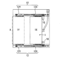
図1は本発明に係るベルト式真空包装装置の要部を示す側面図、図2はその平面図、図3はその正面図である。 FIG. 1 is a side view showing a main part of a belt type vacuum packaging apparatus according to the present invention, FIG. 2 is a plan view thereof, and FIG. 3 is a front view thereof.
本発明のベルト式真空包装装置も、先に説明した従来のベルト式真空包装装置と同様に無端回転する搬送ベルト3を備え、この搬送ベルト3上に包装袋を載せ、搬送ベルト3の走行にともなって、包装袋を真空包装部Iまで搬送し、そこで真空包装をした後、搬送ベルト3を走行させて真空包装済み袋を送り出す。真空包装部Iは、搬送ベルト3を挟んで、搬送ベルト3の上方に位置するチャンバー1と搬送ベルト3の下方に位置するチャンバー台1Aとから構成される。
The belt-type vacuum packaging apparatus of the present invention also includes a
本発明のベルト式真空包装装置では、チャンバー内面の清掃作業や部品交換作業を容易にするため、真空包装をしないときに、チャンバー1を真空包装部Iから搬送ベルト走行方向の上流側、すなわち作業者が位置する装置入口部A側に向けて移動させることができるようにしている。そのため、本実施例では、チャンバー1の両側に、真空包装部Iから装置入口部A側に向けてガイドレール12を設けている。
In the belt-type vacuum packaging apparatus of the present invention, in order to facilitate the cleaning operation of the inner surface of the chamber and the parts replacement operation, when the vacuum packaging is not performed, the
図4はガイドレール12部分の詳細を示す平面図、図5は同じくガイドレール12部分の詳細を示す正面図である。ガイドレール12は、図4に示すように、分割部Sにて、真空包装部I側のガイドレール12Xと装置入口部A側のガイドレール12Yに2分割されている。
4 is a plan view showing details of the
また、図4および図5に示すように、チャンバー1には駆動モーター取り付け用のアーム14を介して駆動モーター10と駆動モーターに取り付けられた駆動ギア11が取り付けられており、この駆動ギア11はガイドレール12上に取り付けられたラック13とかみ合わされている。すなわち、チャンバー1は、駆動モーター10を介して、ガイドレール12Xと一体構造となっている。
As shown in FIGS. 4 and 5, the
また、チャンバー1はアーム14に取り付けられた軸17を介して、ガイドレール12内をスムーズに回転移動する車輪15とレール16による移動機構を備えている。軸17の両端にはベアリングが取り付けられており、回転運動を伝えている。
Further, the
次に、本実施例のベルト式真空包装装置において、通常の真空包装処理を行うときの各部位の動きについて説明する。 Next, in the belt-type vacuum packaging apparatus of the present embodiment, the movement of each part when performing normal vacuum packaging processing will be described.
通常の真空包装処理を行う場合は、真空包装部I部で、真空状態を得るために、チャンバー1を搬送ベルト3に密着させる必要がある。そのため、図1に示すように、チャンバー1をカム18によって上下運動させる。カム18Xの状態がチャンバー1が上昇した位置であり、カム18Yの状態がチャンバー1が下降した位置である。真空状態はカム18Yの状態のチャンバー下降位置にて得られる。
When performing a normal vacuum packaging process, the
ガイドレール12Xは、チャンバー1と共に上下運動する構造になっている。一方、ガイドレール12Yはチャンバーの上下運動とは無関係に固定位置を保っている。ガイドレール12Xはチャンバー1が上昇した位置でガイドレール12Yと同一高さとなり、ガイドレール12Xと12Yとが実質的に接合され1本のガイドレール12となるが、通常の真空処理においては、ガイドレール12はとくにその役目は無い。
The
図6は、通常の真空包装処理を行っている状態でのチャンバー1とガイドレール12の位置関係を模式的に表したものである。このように、通常の真空包装処理においては、ガイドレール12は、12Xと12Yに上下方向に切り離されている。
FIG. 6 schematically shows the positional relationship between the
次に、チャンバー1内面の清掃作業を容易に行うために、チャンバー1を移動させる場合の動きについて説明する。この場合の一連の動作シーケンスは、通常の真空包装処理とは別のシーケンスで行われる。
Next, the movement when the
まず、チャンバー1を上昇させ、搬送ベルト3から切り離した上で、装置入口部A付近位置までチャンバー1を移動させる。このチャンバー1の移動は、ガイドレール12を介して行われる。したがって、移動時にはガイドレール12Xと12Yとが実質的に1本のガイドレール12として接合された状態である必要がある。つまり、図1に示すようにカム18Xの状態により、チャンバー1が上昇した状態である。
First, the
この状態で、駆動モーター10を回転駆動することにより、駆動モーターに取り付けられた駆動ギア11とラック13とが噛み合い、チャンバー1は、ガイドレール12Xとガイドレール12Yを乗り継ぎ、搬送ベルト3と一定間隔Fを保ったまま、装置入口部Aに側に向かって移動する。このとき、ガイドレール12内の車輪15はレール16上を回転移動し、チャンバー1のスムーズな移動を支えている。
In this state, when the
なお、チャンバー1を装置入口部A側に移動させる場合、チャンバー1がオーバーランし、ガイドレール12Yから外れるのを防止するため、チャンバー1をガイドレール12Y終端部付近で確実に停止させる必要がある。そこで、本実施例ではチャンバー1の停止位置を規定するため、図4に示すようにガイドレール12Y終端部近傍にリミットスイッチ20を取り付け、チャンバー1が移動端に達すれば、チャンバー1とリミットスイッチ20が接触し、駆動モーター10が停止し、チャンバー1がオーバーランしないようにしている。
When the
一方、駆動モーター10を逆回転操作すれば、チャンバー1はガイドレール12上を逆走し、元の真空包装部Iの位置に復元する。
On the other hand, if the
この移動前後のチャンバー1の位置関係を図1と図2に示す。1X位置が真空包装時のチャンバー位置であり、1Yが内面清掃作業のために装置入口部A側まで移動させた状態のチャンバー位置である。
The positional relationship of the
また、図1にはチャンバー1を起立させて開放した状態を1X−V、1Y−Vで示す。真空包装部Iでチャンバー1を起立させて開放した状態1X―Vでは、装置入口部Aからチャンバー内面までの距離はGであるが、装置入口部A側でチャンバー1を起立させて開放した状態1Y―Vでは、距離はHとなる。この距離GとHが作業者にとっての清掃作業距離となる。
FIG. 1 shows the state in which the
距離Gは先に説明したとおり約1mであり、従来はチャンバー1が移動しないため、この位置、すなわち装置中央部の真空包装部Iでチャンバー1の開放を行っていた。そのため、作業者が装置中央側面に移動し、片手でチャンバー1を持ち上げながら、チャンバー1の起立固定を行っており、両手が使えない構造になっていた。
The distance G is about 1 m as described above. Conventionally, the
チャンバー1は、真空に耐えられる構造としているため、通常は肉厚堅牢構造となっており、重量も最低50kg程度はある。そのため、従来のチャンバー位置では、チャンバー1を持ち上げ、開放するだけでも容易ではなかった。また、作業者からの距離も約1m離れて開放しているため、できるだけ、距離Gを短縮するため、従来、チャンバー1は図10に示すように前傾姿勢で開放されることが多かった。このような前傾姿勢では内面の清掃がしにくいことは自明である。
Since the
このように、チャンバー1が移動しない従来の真空包装装置では、チャンバーの開放作業そのものが容易でなく、仮に開放しても、清掃しやすい形ではなかった。そのため、実際の清掃作業はできるだけ、作業の煩雑性を避けるため、間隔を延ばす方向で行われてきており、製品の品質面や衛生管理面が犠牲になってきた事実もある。
Thus, in the conventional vacuum packaging apparatus in which the
また、チャンバー内面には、包装袋の密封条件を確保するため、熱シール機構を備えている。この熱シール機構を構成する部品の一部は消耗品であり、一定期間ごとに交換が必要である。しかし、この交換作業も、清掃と同様に、チャンバーを起立させて開放することが必要である。とくに、部品の交換・修理作業は、清掃とは異なり、部品の取り付け状態などが、機械の正常動作を左右することにもなり、そういう意味では清掃以上に困難な作業である。 Further, a heat sealing mechanism is provided on the inner surface of the chamber in order to ensure the sealing conditions of the packaging bag. Some of the parts constituting this heat seal mechanism are consumables and need to be replaced at regular intervals. However, this replacement work also requires that the chamber be raised and opened, as in cleaning. In particular, the replacement / repair work of parts is different from cleaning, and the mounting state of the parts also affects the normal operation of the machine. In that sense, it is more difficult than cleaning.
これに対して、本発明によれば、チャンバー1を作業者の手元まで移動させることができ、作業者との距離Hを従来の距離Gより大幅に短縮することができる。したがって、両手を使い、安定した姿勢でチャンバー1を開放することが可能となる。また、チャンバー1開放時の傾き角度も前傾姿勢ではなく、後傾姿勢とすることができ、チャンバー内面を完全に開放することが可能となる。そのため、チャンバー内面の清掃や、消耗部品の交換作業も極めて容易に行うことができる。
On the other hand, according to the present invention, the
ここで、チャンバー1の移動は、上述のとおり、駆動モーター10の作動によって行われるため、駆動モーター10の停止位置を任意に選択すれば、チャンバー停止位置は任意位置に設定可能である。したがって、作業者の体形や作業内容によってチャンバー停止位置を選択することができる。
Here, since the movement of the
また、チャンバー1を起立させて開放したままの状態でも、チャンバー1の移動および任意位置での停止が可能であり、作業の応用性も広がる。
In addition, even when the
なお、本発明においてチャンバー1開放時の傾き角度は上述のように、前傾姿勢ではなく後傾姿勢とすることができるので、本発明では、先に図9および図10で説明した従来技術のようにチャンバーが前傾姿勢から前方に倒れるのを防止するための機構(チャンバーストッパーやチャンバーブラケット)は不要である。すなわち、本発明によれば、チャンバー1開放時には、チャンバー1をただ後に傾かせるだけであり、その停止位置は例えば駆動モーター10に取り付けたアーム等によって規定することができる。
In the present invention, the tilt angle when the
作業終了後は、チャンバー1を倒し、駆動モーター10を逆転することにより、チャンバー1を正規の真空包装部Iに戻す。
After completion of the operation, the
以上、本実施例では駆動モーター方式によるチャンバー移動について説明したが、駆動モーター方式に限定する必要はなく、カウンターウェイト方式などによってもチャンバー移動は可能である。ベルト式真空包装装置では、液汁の入った製品を真空包装する場合、包装袋を搬送ベルト上に載せるときに液汁のコボレを防止するため、装置全体を前傾させることが多い。このような前傾姿勢でカウンターウェイト方式を採用すれば、人力でのチャンバー移動も可能となる。 As described above, the chamber movement by the drive motor method has been described in this embodiment, but it is not necessary to limit to the drive motor method, and the chamber movement is also possible by a counterweight method or the like. In a belt-type vacuum packaging apparatus, when a product containing liquid juice is vacuum-packed, the entire apparatus is often tilted forward in order to prevent the liquid juice from collapsing when the packaging bag is placed on the transport belt. If the counterweight system is employed in such a forward leaning posture, the chamber can be moved manually.
本発明を適用したベルト式真空包装装置と従来のベルト式真空包装装置を用いて、チャンバー内面の清掃時間と熱シール機構の消耗部品の取替え時間を5人の作業者による所要時間で比較した。 Using the belt-type vacuum packaging apparatus to which the present invention is applied and the conventional belt-type vacuum packaging apparatus, the cleaning time of the chamber inner surface and the replacement time of the consumable parts of the heat seal mechanism were compared with the time required by five workers.
表1は、チャンバー内面の清掃時間の比較結果である。全作業者とも、本発明での清掃時間が従来技術での清掃時間を下回っている。 Table 1 shows a comparison result of the cleaning time of the chamber inner surface. For all workers, the cleaning time in the present invention is less than the cleaning time in the prior art.
表2は熱シール機構の消耗部品の取替え時間の比較である。結果は清掃時間と同様の傾向であった。 Table 2 shows a comparison of replacement times for consumable parts of the heat seal mechanism. The result was the same tendency as the cleaning time.
このように、本発明の有効性は実際の作業時間のデータによっても明らかに認められる。

1 チャンバー
1X 真空包装部位置のチャンバー
1Y 装置入口部側位置のチャンバー
2 包装袋
3 搬送ベルト
4 袋押さえ
5 チャンバーストッパー
5A チャンバーストッパーの下端
6 チャンバーブラケット
6A;チャンバーブラケットのザグリ孔
7 排出シュート
8 チャンバーサポート
9 本体フレーム
10 駆動モーター
11 駆動ギア
12 ガイドレール
12X 真空包装部側のガイドレール
12Y 装置入口側のガイドレール
13 ラック
14 アーム
15 車輪
16 レール
17 軸
18 カム
18X チャンバー上昇位置のカム
18Y チャンバー下降位置のカム
19 操作盤
20 リミットスイッチ
A 装置入口部
B 搬送ベルト進行方向
C チャンバー端部
D 装置入口側のベルト端部
E 作業スペース
F チャンバーの幅
G 作業者とチャンバー内面間距離(従来技術)
H 作業者とチャンバー内面間距離(本発明)
P 作業者
DESCRIPTION OF
H Distance between worker and chamber inner surface (Invention)
P worker
Claims (1)
Priority Applications (1)
| Application Number | Priority Date | Filing Date | Title |
|---|---|---|---|
| JP2006345021A JP4881148B2 (en) | 2006-12-21 | 2006-12-21 | Belt type vacuum packaging equipment |
Applications Claiming Priority (1)
| Application Number | Priority Date | Filing Date | Title |
|---|---|---|---|
| JP2006345021A JP4881148B2 (en) | 2006-12-21 | 2006-12-21 | Belt type vacuum packaging equipment |
Publications (2)
| Publication Number | Publication Date |
|---|---|
| JP2008155930A JP2008155930A (en) | 2008-07-10 |
| JP4881148B2 true JP4881148B2 (en) | 2012-02-22 |
Family
ID=39657312
Family Applications (1)
| Application Number | Title | Priority Date | Filing Date |
|---|---|---|---|
| JP2006345021A Active JP4881148B2 (en) | 2006-12-21 | 2006-12-21 | Belt type vacuum packaging equipment |
Country Status (1)
| Country | Link |
|---|---|
| JP (1) | JP4881148B2 (en) |
Families Citing this family (1)
| Publication number | Priority date | Publication date | Assignee | Title |
|---|---|---|---|---|
| JP5946340B2 (en) * | 2012-07-06 | 2016-07-06 | 株式会社古川製作所 | Belt type vacuum packaging machine |
-
2006
- 2006-12-21 JP JP2006345021A patent/JP4881148B2/en active Active
Also Published As
| Publication number | Publication date |
|---|---|
| JP2008155930A (en) | 2008-07-10 |
Similar Documents
| Publication | Publication Date | Title |
|---|---|---|
| JP6482046B2 (en) | Roller conveyor device and plate material loading / unloading / sorting device equipped with the roller conveyor device | |
| TWI445501B (en) | Shellfish positioning and opening apparatus and method thereof | |
| KR101727723B1 (en) | Immersion device for rubber gloves manufacture | |
| KR102181281B1 (en) | Article transfer device | |
| JP5751189B2 (en) | Filter press cleaning device for filter press | |
| CN113081833B (en) | Traditional Chinese medicine decoction system and traditional Chinese medicine decoction method | |
| US5368652A (en) | Method for purging and decontaminating a product-containing storage drum | |
| JP2011042503A (en) | Crane device for wrapped quartz glass crucible and method for packing wrapped quartz glass crucible using the same | |
| CN208427506U (en) | Turnover mechanism, cleaning equipment and assembly line | |
| JP2016069190A (en) | Conveying device and method for separating foreign objects from conveying surface of conveying device | |
| JP4881148B2 (en) | Belt type vacuum packaging equipment | |
| JP6803669B2 (en) | Screen printing machine | |
| JP2003251293A (en) | Preliminary cleaning apparatus | |
| CN201484678U (en) | Sealing device of aluminum box packager | |
| JP5236635B2 (en) | Apparatus for processing flexible hose-like formations, in particular bags | |
| CN214269308U (en) | Clamping type stacker crane | |
| CN107900247A (en) | A kind of automatic production line for coordinating industrial robot work | |
| JP5946340B2 (en) | Belt type vacuum packaging machine | |
| CN101633413B (en) | Sealing device of aluminum box packaging machine | |
| JP4157533B2 (en) | Vacuum packaging machine | |
| JP5937189B2 (en) | Crane apparatus for packaged quartz glass crucible and packing method for packaged quartz glass crucible using this apparatus | |
| CN218142404U (en) | Conveying assembly for production of filling and sealing film products | |
| JP3852094B2 (en) | Container cleaning equipment | |
| CN217963974U (en) | Multifunctional bottle washing machine | |
| CN218142494U (en) | Film sealing device |
Legal Events
| Date | Code | Title | Description |
|---|---|---|---|
| A621 | Written request for application examination |
Free format text: JAPANESE INTERMEDIATE CODE: A621 Effective date: 20091105 |
|
| A977 | Report on retrieval |
Free format text: JAPANESE INTERMEDIATE CODE: A971007 Effective date: 20111025 |
|
| TRDD | Decision of grant or rejection written | ||
| A01 | Written decision to grant a patent or to grant a registration (utility model) |
Free format text: JAPANESE INTERMEDIATE CODE: A01 Effective date: 20111104 |
|
| A01 | Written decision to grant a patent or to grant a registration (utility model) |
Free format text: JAPANESE INTERMEDIATE CODE: A01 |
|
| A61 | First payment of annual fees (during grant procedure) |
Free format text: JAPANESE INTERMEDIATE CODE: A61 Effective date: 20111202 |
|
| R150 | Certificate of patent or registration of utility model |
Free format text: JAPANESE INTERMEDIATE CODE: R150 Ref document number: 4881148 Country of ref document: JP Free format text: JAPANESE INTERMEDIATE CODE: R150 |
|
| FPAY | Renewal fee payment (event date is renewal date of database) |
Free format text: PAYMENT UNTIL: 20141209 Year of fee payment: 3 |
|
| A521 | Request for written amendment filed |
Free format text: JAPANESE INTERMEDIATE CODE: A523 Effective date: 20120112 |
|
| A072 | Dismissal of procedure [no reply to invitation to correct request for examination] |
Free format text: JAPANESE INTERMEDIATE CODE: A072 Effective date: 20120706 |
|
| R250 | Receipt of annual fees |
Free format text: JAPANESE INTERMEDIATE CODE: R250 |
|
| R250 | Receipt of annual fees |
Free format text: JAPANESE INTERMEDIATE CODE: R250 |
|
| R250 | Receipt of annual fees |
Free format text: JAPANESE INTERMEDIATE CODE: R250 |
|
| R250 | Receipt of annual fees |
Free format text: JAPANESE INTERMEDIATE CODE: R250 |
|
| R250 | Receipt of annual fees |
Free format text: JAPANESE INTERMEDIATE CODE: R250 |
|
| R250 | Receipt of annual fees |
Free format text: JAPANESE INTERMEDIATE CODE: R250 |
|
| R250 | Receipt of annual fees |
Free format text: JAPANESE INTERMEDIATE CODE: R250 |
|
| R250 | Receipt of annual fees |
Free format text: JAPANESE INTERMEDIATE CODE: R250 |
|
| R250 | Receipt of annual fees |
Free format text: JAPANESE INTERMEDIATE CODE: R250 |
|
| R250 | Receipt of annual fees |
Free format text: JAPANESE INTERMEDIATE CODE: R250 |