JP4881027B2 - Fuel cell system and method for starting fuel cell at low temperature - Google Patents
Fuel cell system and method for starting fuel cell at low temperature Download PDFInfo
- Publication number
- JP4881027B2 JP4881027B2 JP2006030052A JP2006030052A JP4881027B2 JP 4881027 B2 JP4881027 B2 JP 4881027B2 JP 2006030052 A JP2006030052 A JP 2006030052A JP 2006030052 A JP2006030052 A JP 2006030052A JP 4881027 B2 JP4881027 B2 JP 4881027B2
- Authority
- JP
- Japan
- Prior art keywords
- fuel cell
- freezing
- starting
- temperature
- sub
- Prior art date
- Legal status (The legal status is an assumption and is not a legal conclusion. Google has not performed a legal analysis and makes no representation as to the accuracy of the status listed.)
- Active
Links
Images


Classifications
-
- Y—GENERAL TAGGING OF NEW TECHNOLOGICAL DEVELOPMENTS; GENERAL TAGGING OF CROSS-SECTIONAL TECHNOLOGIES SPANNING OVER SEVERAL SECTIONS OF THE IPC; TECHNICAL SUBJECTS COVERED BY FORMER USPC CROSS-REFERENCE ART COLLECTIONS [XRACs] AND DIGESTS
- Y02—TECHNOLOGIES OR APPLICATIONS FOR MITIGATION OR ADAPTATION AGAINST CLIMATE CHANGE
- Y02E—REDUCTION OF GREENHOUSE GAS [GHG] EMISSIONS, RELATED TO ENERGY GENERATION, TRANSMISSION OR DISTRIBUTION
- Y02E60/00—Enabling technologies; Technologies with a potential or indirect contribution to GHG emissions mitigation
- Y02E60/30—Hydrogen technology
- Y02E60/50—Fuel cells
Description
この発明は、燃料電池を、水の氷点以下の温度で正常に起動させる燃料電池システム及び燃料電池の低温下起動方法に関する。 The present invention relates to a fuel cell system for normally starting a fuel cell at a temperature below the freezing point of water and a method for starting the fuel cell at a low temperature.
例えば、固体高分子型燃料電池は、高分子イオン交換膜からなる電解質膜の両側に、それぞれアノード電極(燃料極)及びカソード電極(酸化剤極)を設けた電解質膜・電極構造体を、セパレータによって挟んで保持している。この燃料電池は、通常、電解質膜・電極構造体及びセパレータを所定数だけ交互に積層することにより、燃料電池スタックとして使用されている。 For example, in a polymer electrolyte fuel cell, an electrolyte membrane / electrode structure in which an anode electrode (fuel electrode) and a cathode electrode (oxidant electrode) are provided on both sides of an electrolyte membrane made of a polymer ion exchange membrane is used as a separator. Is held between. This fuel cell is normally used as a fuel cell stack by alternately laminating a predetermined number of electrolyte membrane / electrode structures and separators.
この燃料電池において、アノード電極に供給された燃料ガス、例えば、水素含有ガスは、電極触媒上で水素がイオン化され、電解質膜を介してカソード側電極側へと移動する。その間に生じた電子は外部回路に取り出され、直流の電気エネルギとして利用される。なお、カソード電極には、酸化剤ガス、例えば、空気等の酸素含有ガスが供給されているために、このカソード電極において、水素イオン、電子及び酸素が反応して水が生成される。 In this fuel cell, a fuel gas, for example, a hydrogen-containing gas, supplied to the anode electrode is ionized on the electrode catalyst and moves to the cathode side electrode side through the electrolyte membrane. Electrons generated during that time are taken out to an external circuit and used as direct current electric energy. Since the cathode electrode is supplied with an oxidant gas, for example, an oxygen-containing gas such as air, water reacts with the hydrogen ions, electrons, and oxygen at the cathode electrode.
ところで、この種の燃料電池では、イオン導電性を維持するために、電解質膜を適度に加湿しておく必要がある。さらに、カソード電極では、上記のように反応による生成水が存在している。このため、燃料電池を氷点下(水の凍結温度以下)で起動させようとすると、前記燃料電池内の水分が凍結し易く、該燃料電池内で電気化学反応が行われ難いという不具合が指摘されている。 By the way, in this type of fuel cell, it is necessary to appropriately humidify the electrolyte membrane in order to maintain ionic conductivity. Furthermore, water produced by the reaction is present at the cathode electrode as described above. For this reason, when starting the fuel cell below freezing point (below the freezing temperature of water), the water in the fuel cell is likely to freeze, and it is pointed out that the electrochemical reaction is difficult to occur in the fuel cell. Yes.
そこで、例えば、特許文献1には、Dupont社製のNAFION(登録商標)及びDow社製の実験用膜(商品番号XUX 13204.10)のような電解質膜は、−20℃の温度であっても十分にイオン的に伝導性を有して燃料電池内で電気化学反応が可能であることが開示されている。
Therefore, for example,
しかしながら、上記の特許文献1では、作動開始後の約4分間、水素の流れる通路が水又は氷により塞がれてしまい、水素の流れが適切に行われていないという問題がある。さらに、4分後に50アンペアの負荷に接続されると、約45アンペアの出力が得られたものの、出力電流は約8秒で約15アンペアまで低下してしまう。これは、生成水が凍結したからである。
However, in the above-mentioned
このように、特許文献1では、氷点下以下であっても、燃料電池の起動が可能になるものの、氷や生成水の凍結によって所望の発電状態に迅速に移行することが困難であるという問題がある。
As described above, in
この問題を解決する技術が特許文献2に提案されている。 A technique for solving this problem is proposed in Patent Document 2.
この特許文献2に提案された技術は、水点下の環境において、図7に示すように、特定電圧下で出力電流が両反応ガスのガス圧力によって変動し、電圧降下を誘発することがなく、安定して最大電流を取り出すことができる因果関係を利用している。 In the technique proposed in Patent Document 2, the output current fluctuates depending on the gas pressures of both reaction gases under a specific voltage in an environment below the water point, as shown in FIG. 7, without inducing a voltage drop. Utilizing a causal relationship that can stably extract the maximum current.
すなわち、両反応ガスのガス圧力が高くなるのに比例して、取り出される出力電流が増加する。 That is, the output current to be taken out increases in proportion to the increase in the gas pressure of both reaction gases.
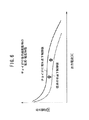
さらに、特許文献2に提案された技術は、水の凍結温度以下の環境において、特定電圧下で、両反応ガスのガス圧力の高低と限界負荷とが、図8に示す関係を有し、前記ガス圧力が通常運転条件のガス圧力より高く設定されると、安定して取り出すことができる限界負荷(最大出力電流)が大きくなるという特質が得られるという因果関係を利用している。 Furthermore, the technique proposed in Patent Document 2 has the relationship shown in FIG. 8 between the high and low gas pressures of both reaction gases and the limit load under a specific voltage in an environment below the freezing temperature of water. When the gas pressure is set higher than the gas pressure of the normal operation condition, a causal relationship is obtained that a characteristic that the limit load (maximum output current) that can be stably taken out is increased is obtained.
すなわち、氷点下起動に際し、残留水が電極触媒やガス拡散層に凍結した状態で存在していると、電極反応面積が低下して反応ガスの拡散性が著しく低下する。そこで、氷点下起動の際に、上記特許文献2に係る従来の低温下起動技術では、供給する反応ガスのガス圧力を高めることにより、電極反応が起こる反応部位に反応ガスを確実に供給することができ、取り出し可能な出力電流が向上するものと考えられる。しかも、氷点下起動の環境において、反応ガスのガス圧力を高めることは、通常運転状態で反応ガスのガス圧力を高めるよりも、発電特性を向上させる効果が大きい。 That is, when the residual water is present in a frozen state in the electrode catalyst or the gas diffusion layer at the time of starting below freezing point, the electrode reaction area is reduced and the diffusibility of the reaction gas is significantly reduced. Therefore, at the time of starting below the freezing point, the conventional low temperature starting technology according to Patent Document 2 can reliably supply the reaction gas to the reaction site where the electrode reaction occurs by increasing the gas pressure of the reaction gas to be supplied. This is considered to improve the output current that can be taken out. Moreover, in the environment where the temperature is below freezing, increasing the gas pressure of the reaction gas has a greater effect of improving the power generation characteristics than increasing the gas pressure of the reaction gas in a normal operation state.
ところで、氷点下での燃料電池システムの停止時に、イグニッションスイッチをオン状態として燃料電池システムを氷点下で起動したとき、燃料電池の暖機が不十分なまま、運転者等の操作者の都合等によりイグニッションスイッチがオフ状態にされる可能性がある。 By the way, when the fuel cell system is stopped below the freezing point, when the fuel cell system is started below the freezing point with the ignition switch turned on, the ignition of the fuel cell system is insufficient due to the convenience of the operator such as the driver. The switch may be turned off.
このような、氷点下短時間発電後停止要求の操作(氷点下起動後に発電短時間にて燃料電池システムを停止させる操作、換言すれば、氷点下で燃料電池システムをちょっと起動した後すぐに停止させる操作、いわゆるチョイがけ操作)がなされてシステムが停止させられた後、再度、氷点下での起動(氷点下短時間発電後停止後再起動、換言すればチョイがけ後の再起動)が行われた場合には、上述した特許文献2に記載された従来技術に係る氷点下制御技術により起動した場合であっても、図9に示すように、最初の氷点下起動時の電流・電圧特性に比較して、再起動時の氷点下起動時(氷点下短時間発電後停止後再起動時=チョイがけ後再起動時)の電流・電圧特性が悪化してしまうことが分かった。 Such an operation of a stop request after power generation for a short time below freezing (operation to stop the fuel cell system in a short time after power generation after starting below freezing, in other words, an operation to stop the fuel cell system immediately after starting slightly below freezing, When the system is stopped after a so-called “choking operation” is performed, the system is again restarted below freezing point (after power generation is stopped for a short time after freezing and then restarted, in other words, restarting after choking) Even when activated by the below-freezing point control technology according to the prior art described in the above-mentioned Patent Document 2, as shown in FIG. It has been found that the current / voltage characteristics at the time of starting below freezing at the time (when restarting after stopping after power generation for a short time below freezing = when restarting after peeling off) deteriorate.
この発明はこの種の問題を解決するものであり、氷点下短時間発電後停止後再起動時(チョイがけ後の再起動時)における電流・電圧特性を良化させることを可能とする燃料電池システム及び燃料電池の低温下起動方法を提供することを目的とする。 The present invention solves this type of problem, and makes it possible to improve the current / voltage characteristics at the time of restart after power generation after a short period of freezing and at the time of restart (after restart). And it aims at providing the starting method under low temperature of a fuel cell.
この発明に係る燃料電池システムは、供給される反応ガスにより発電を行う燃料電池を備える燃料電池システムにおいて、以下の特徴(1)〜(3)を有する。 The fuel cell system according to the present invention is a fuel cell system including a fuel cell that generates electric power using supplied reaction gas, and has the following features (1) to (3).
(1)前記燃料電池の内部温度を検知する内部温度検知手段と、前記燃料電池の停止期間に、前記内部温度が氷点以下の温度になったことを記憶する氷点下経験記憶手段と、前記燃料電池の起動時に、この起動時前の停止期間に氷点下の温度になったことが前記氷点下経験記憶手段に記憶されていたとき、通常起動時に比較して前記反応ガスの圧力を増圧して前記燃料電池を起動させる氷点下第1起動手段と、前記氷点下第1起動手段による起動後の停止時に、前記燃料電池の暖機が十分な状態で停止されたかどうかを判断する暖機状態判断手段と、暖機が十分な状態ではないと判断されて停止された後の前記燃料電池の再起動時に、この再起動時前の停止期間に氷点下の温度になったことが前記氷点下経験記憶手段に記憶されていたとき、前記氷点下第1起動手段による前記反応ガスの圧力をさらに増圧して前記燃料電池を起動させる氷点下第2起動手段とを備えることを特徴とする。 (1) Internal temperature detection means for detecting the internal temperature of the fuel cell, sub-freezing experience storage means for storing that the internal temperature has become below the freezing point during the stop period of the fuel cell, and the fuel cell When the temperature below sub-freezing temperature is stored in the sub-freezing experience storage means at the start-up time of the start-up, the pressure of the reaction gas is increased compared with the normal start-up, and the fuel cell First freezing point starting means for starting the fuel cell, warming state determining means for determining whether or not the warming of the fuel cell has been stopped in a sufficient state at the time of stopping after the starting by the first below freezing point means, When the fuel cell was restarted after it was determined that the temperature was not sufficient, it was stored in the sub-freezing experience storage means that the temperature was below the freezing point during the stop period before the restarting. When Serial below freezing by applying further increasing the pressure of the reaction gas by the first start means, characterized in that it comprises a sub-zero second activation means for activating the fuel cell.
この特徴(1)を有する発明によれば、燃料電池の起動時に、燃料電池が氷点下状態にあった場合、又は氷点下状態にある場合、氷点下第1起動手段により、通常起動時に比較して反応ガスの圧力を増圧して前記燃料電池を起動し、前記氷点下第1起動手段による起動後、前記燃料電池の暖機が不十分な状態で発電が停止された後の燃料電池の再起動時(チョイがけ後の再起動時)に、燃料電池が氷点下状態にあった場合、又は氷点下状態にある場合、氷点下第2起動手段により、前記氷点下第1起動手段による前記反応ガスの圧力をさらに増圧して前記燃料電池を起動させるようにしているので、氷点下短時間発電後停止後再起動時(チョイがけ後の再起動時)における電流・電圧特性を良化させることができる。 According to the invention having the feature (1), when the fuel cell is in a sub-freezing state or in a sub-freezing state at the time of starting the fuel cell, the reaction gas is compared with the normal starting by the sub-freezing first starting means. The fuel cell is started up by increasing the pressure of the fuel cell, and after the startup by the first below-freezing means, the fuel cell is restarted after the power generation is stopped in a state where the fuel cell is not sufficiently warmed up (choi When the fuel cell is in a sub-freezing state or when it is in a sub-freezing state at the time of restarting after ashing, the reaction gas pressure by the sub-freezing first starting unit is further increased by the sub-freezing second starting unit. Since the fuel cell is started up, the current / voltage characteristics at the time of restarting after stopping after power generation for a short time below freezing point (at the time of restarting after choking) can be improved.
(2)前記特徴(1)を有する発明において、請求項1記載の燃料電池システムにおいて、前記氷点下第1起動手段による起動時における前記反応ガスの流量は、通常起動時の前記反応ガスの流量に比較して増量され、前記氷点下第2起動手段による再起動時における前記反応ガスの流量は、前記氷点下第1起動手段により増量した流量よりさらに増量されることを特徴とする。
(2) In the invention having the feature (1), in the fuel cell system according to
この特徴(2)を有する発明によれば、増加された反応ガスの流量によりカソード電極側の生成水を燃料電池の外部に、より確実に排出することができるので、生成水の凍結によるガス拡散性能の低下を抑制することができる。 According to the invention having the feature (2), the generated water on the cathode electrode side can be more reliably discharged to the outside of the fuel cell by the increased flow rate of the reaction gas. A decrease in performance can be suppressed.
(3)前記特徴(1)又は(2)を有する発明において、前記暖機状態判断手段は、前記氷点下第1起動手段による発電開始時の前記燃料電池の内部温度と、前記氷点下第1起動手段による起動後における発電終了時の内部温度とに基づき前記燃料電池の暖機が十分な状態であるかどうかを判断することを特徴とする。 (3) In the invention having the feature (1) or (2), the warm-up state determination means includes the internal temperature of the fuel cell at the start of power generation by the first below-freezing start means and the first below-freezing start means. And determining whether or not the fuel cell is sufficiently warmed up based on the internal temperature at the end of power generation after startup by the above.
この特徴(3)を有する発明によれば、氷点下第2起動手段による起動が必要かどうかを、自動的に判断することができる。 According to the invention having the feature (3), it is possible to automatically determine whether or not the activation by the below-freezing second activation means is necessary.
この場合、基本的に、発電開始時の内部温度が氷点温度に近い場合には、発電終了時の内部温度が比較的に低くても暖機が十分であると判定し、発電開始時の内部温度が氷点温度に比較して低温である場合には低温になるほど、発電終了時の内部温度がより高い温度でないと暖機が不十分であると判定することができる。 In this case, basically, if the internal temperature at the start of power generation is close to the freezing point temperature, it is determined that the warm-up is sufficient even if the internal temperature at the end of power generation is relatively low. When the temperature is lower than the freezing point temperature, it can be determined that the warm-up is insufficient unless the internal temperature at the end of power generation is higher as the temperature is lower.
(4)この発明に係る燃料電池の低温下起動方法は、供給される反応ガスにより発電を行う燃料電池の低温下起動方法において、前記燃料電池の内部温度を検知する内部温度検知ステップと、前記燃料電池の停止期間に、前記内部温度が氷点以下の温度になったことを記憶する氷点下経験記憶ステップと、前記燃料電池の起動時に、この起動時前の停止期間に氷点下の温度になったことが前記氷点下経験記憶ステップで記憶されていたとき、通常起動時に比較して前記反応ガスの圧力を増圧して前記燃料電池を起動させる氷点下第1起動ステップと、前記氷点下第1起動ステップによる起動後の停止時に、前記燃料電池の暖機が十分な状態で停止されたかどうかを判断する暖機状態判断ステップと、暖機が十分な状態ではないと判断されて停止された後の前記燃料電池の再起動時に、この再起動時前の停止期間に氷点下の温度になったことが前記氷点下経験記憶ステップで記憶されていたとき、前記氷点下第1起動ステップによる前記反応ガスの圧力をさらに増圧して前記燃料電池を起動させる氷点下第2起動ステップとを備えることを特徴とする。 (4) A low temperature start-up method for a fuel cell according to the present invention is a low-temperature start-up method for a fuel cell that generates power using a supplied reaction gas, and an internal temperature detection step for detecting an internal temperature of the fuel cell; The below-freezing experience storage step for storing that the internal temperature has become below the freezing point during the stop period of the fuel cell, and at the start-up period of the fuel cell, the temperature has been below the freezing point during the stop period before the start-up. Is stored in the below-freezing experience storing step, the first starting step below the freezing point for starting the fuel cell by increasing the pressure of the reaction gas compared to the normal starting time, and after the starting by the first starting step below the freezing point A warm-up state determination step for determining whether or not the fuel cell has been warmed up in a sufficient state at the time of stopping, and a stop when it is determined that the warm-up is not in a sufficient state. When the fuel cell is restarted after being operated, when the temperature below the freezing point is stored in the subzero freezing experience storing step during the stop period before the restarting, the reaction by the first starting step below the freezing point is performed. And a second sub-freezing start step for starting the fuel cell by further increasing the pressure of the gas.
この特徴(4)を有する発明によれば、燃料電池が氷点下状態にあった場合、又は氷点下状態にある場合の起動時に、氷点下第1起動ステップにより、通常起動時に比較して反応ガスの圧力を増圧して前記燃料電池を起動させ、前記氷点下第1起動ステップによる起動後、前記燃料電池の暖機が不十分な状態で発電が停止された後の燃料電池の再起動時(チョイがけ後の再起動時)に、燃料電池が氷点下状態にあった場合、又は氷点下状態にある場合、氷点下第2起動ステップにより、前記氷点下第1起動ステップにおける前記反応ガスの圧力をさらに増圧して前記燃料電池を起動させるようにしているので、氷点下短時間発電後停止後再起動時(チョイがけ後の再起動時)における電流・電圧特性を良化させることができる。 According to the invention having the feature (4), when the fuel cell is in a sub-freezing state or when the fuel cell is in a sub-freezing state, the pressure of the reaction gas is reduced by the first sub-freezing start step as compared with the normal starting time. The fuel cell is started up by increasing the pressure, and after the start-up by the first freezing step below the freezing point, when the fuel cell is restarted after power generation is stopped due to insufficient warm-up of the fuel cell (after choking) When the fuel cell is in a sub-freezing state or at a sub-freezing state at the time of restart), the fuel cell is further increased in the first sub-freezing step by increasing the pressure of the reaction gas in the sub-freezing second starting step. Therefore, it is possible to improve the current / voltage characteristics at the time of power generation after a short period of freezing and restarting after stopping (when restarting after choking).
この発明によれば、氷点下短時間発電後に停止された後の再起動時に、反応ガスの圧力を、前回の氷点下起動時おける反応ガスの圧力に比較して増加させるようにしているので、氷点下短時間発電後停止後再起動時(チョイがけ後の再起動時)における電流・電圧特性を良化させることができる。 According to the present invention, at the time of restart after being stopped after power generation for a short time below freezing point, the pressure of the reaction gas is increased compared to the pressure of the reaction gas at the time of the previous freezing point start. It is possible to improve the current / voltage characteristics at the time of restart after stop after time power generation (at the time of restart after choking).
また、燃料電池システムの氷点下短時間発電後停止後再起動時(チョイがけ後の再起動時)において、従来の氷点下起動制御よりアノード電極側作動圧の増圧、カソード電極側作動圧の増圧、カソード電極側反応ガスの流量の増加を行うため、発電に必要な反応ガスをより燃料電池に配給することができる。 In addition, when the fuel cell system is restarted after power generation for a short time after freezing (after restarting after choking), the anode electrode side operating pressure is increased and the cathode electrode side operating pressure is increased compared to the conventional below-freezing start control. Since the flow rate of the cathode electrode side reaction gas is increased, the reaction gas necessary for power generation can be more distributed to the fuel cell.
この発明によれば、氷点下起動時における起動性能が向上する。 According to this invention, the starting performance at the time of starting below freezing improves.
なお、この実施形態において、上述した「氷点下短時間発電後停止」は、分かりやすさを考慮し、原則として「チョイがけ」という。 In this embodiment, the “stop after a short period of freezing power generation” described above is called “choking” as a general rule in consideration of easy understanding.
図1は、この発明の実施形態に係る燃料電池の低温下起動方法を実施するための燃料電池システム10の概略構成説明図である。
FIG. 1 is a schematic configuration explanatory view of a
燃料電池システム10は、例えば、自動車等の車両に搭載されており、燃料電池(FC)12を備える。
The
燃料電池12は、固体高分子電解質膜の両側にアノード電極とカソード電極とを配置した電解質膜・電極構造体を反応ガス流路が形成された一対のセパレータで挟んで保持して構成される燃料電池セルを、複数積層させて一体化させたスタック構造になっている。
The
燃料電池12には、一方の反応ガスである燃料ガス、ここでは水素ガスを供給するための水素供給口20と、燃料電池12から排出される未使用の水素ガスを含む排ガスを排出するための水素排出口22と、燃料電池12に、他方の反応ガスである酸化剤ガス、ここでは空気を供給するための空気供給口24と、未使用の酸素を含む空気を燃料電池12から排出するための空気排出口26とが設けられている。
The
燃料電池システム10は、燃料ガス供給系28と、酸化剤ガス供給系30と、図示しない冷却媒体供給系とを備える。燃料ガス供給系28は、燃料電池12に水素ガスを供給する水素供給流路32と、燃料電池12から未使用の水素ガスを含む排ガスを排出する水素排出流路33と、排ガスを水素供給流路32の途上に戻して燃料電池12に供給するための水素循環流路34とを備える。
The
水素供給流路32には、高圧水素を貯留する水素タンク36と、高圧水素を遮断又は開放する遮断弁37と、水素タンク36から遮断弁37を通じて供給される水素ガスの圧力を減圧し圧力を調整する圧力調整弁38と、減圧された水素ガスを燃料電池12に供給するとともに、水素循環流路34から排ガスを吸引して燃料電池12に戻すためのエゼクタ40と、燃料電池12に供給される水素ガスの圧力を検出する圧力計42とが設けられる。
The hydrogen
水素排出流路33には、燃料電池12から排出される排ガスを廃棄するための水素排出弁44が設けられる一方、水素循環流路34には、燃料電池12に供給される水素ガスの流量を制御するための水素ポンプ46が設けられる。
The hydrogen
酸化剤ガス供給系30は、燃料電池12に空気を供給する空気供給流路48と、燃料電池12から排出される未使用の空気を含む排ガスを外部に廃棄するための空気排出流路50とを備える。
The oxidant
空気供給流路48には、空気を圧縮して供給するためのエアコンプレッサ52と、燃料電池12に供給される空気の圧力を検出する圧力計54とが設けられる。空気排出流路50には、燃料電池12の空気出口温度を燃料電池12の内部温度(パワープラント内温度ともいう。)Ti[℃]として検知する温度計(内部温度検知手段)56と、燃料電池12に供給される空気の圧力を制御するための背圧調整弁58とが設けられる。
The
なお、燃料電池12の内部温度Tiは、空気出口温度に限らず、水素ガス入口温度、水素ガス出口温度、燃料電池12の筐体温度、冷却媒体の温度のいずれかを使用でき、状況に応じて2つ以上を使用してもよい。また、燃料電池12の内部温度Tiは、燃料電池システム10の発電中及び停止中のいずれの期間においても、所定時間毎に測定され、メモリ61に時刻をアドレスとして連続的に記憶される。
The internal temperature Ti of the
さらに、燃料電池システム10には、CPU(制御装置)60が設けられる。CPU60は、遮断弁37及び水素排出弁44の開弁・閉弁制御(指令)、エアコンプレッサ52の回転数制御(指令)に基づく吐出空気量(流量)の調整、水素ポンプ46の回転数制御(指令)に基づく水素ガスの流量の調整、圧力調整弁38の弁開度の制御(指令)による水素ガス圧力の調整、背圧調整弁58の弁開度の制御(指令)による酸化剤ガス圧力の調整等を含め、燃料電池システム10の全ての動作を制御する。
Further, the
この実施形態において、CPU60は、圧力計42、54からの圧力、温度計56からの内部温度、図示しないイグニッションスイッチのオンオフ操作等の各種入力に基づきメモリ61に記憶されているプログラムを実行することで、上記の各種弁37、38、44、58、エアコンプレッサ52、水素ポンプ46を制御して各種の機能を実現する機能手段としても動作する。
In this embodiment, the
なお、メモリ61には、ROM、RAM、EEPROMが含まれ、メモリ61のEEPROMは、氷点下経験記憶手段として機能する。
The
この実施形態において、CPU60は、氷点下第1起動手段、暖機状態判断手段(低温下起動後短時間発電判断手段)、及び氷点下第2起動手段の一部又は全部として機能する他、計時手段(カウンタ・タイマ)等として機能する。
In this embodiment, the
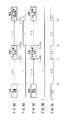
このように構成される燃料電池システム10の動作について、図2、図3に示すフローチャート及び図4A〜図4Eに示すチョイがけ経験有無判定タイムチャートに沿って以下に説明する。なお、図4A、図4B、図4Fは、チョイがけ経験有りの場合のタイムチャート、図4C、図4D、図4Eは、チョイがけ経験無しの場合のタイムチャートを示している。
The operation of the
図4A〜図4Eのタイムチャート中、時点t0まで燃料電池システム10が常温(周囲温度が0[℃]以上)で発電を行い、その時点t0でイグニッションスイッチがオン状態からオフ状態にされた後の燃料電池システム10の停止中、いわゆるソーク中(燃料電池12の停止期間中)に、時点t1に示すように、ステップS1において、イグニッションスイッチがオフ状態からオン状態になったことが検知されると、ステップS2において、燃料電池12の氷点下起動制御が必要かどうかが判断される。
In the time charts of FIGS. 4A to 4E, the
このステップS2の判断は、時点t0〜時点t1のソーク中に、温度計56により測定されている燃料電池12の内部温度Tiが氷点下以下の温度となった経験があるかどうか(Ti<0℃)、又は時点t1での内部温度Ti{発電開始時の内部温度Tsという(Ti=Ts)。}が氷点下以下の温度であるかどうか(Ti=Ts<0℃)により判断される。
The determination in step S2 is performed whether or not the internal temperature Ti of the
ステップS2の判断が成立しないときには、氷点下起動制御が不要とされ、ステップS3において、通常の起動制御が行われる。通常の起動制御とは、圧力調整弁38の水素ガスの圧力制御による燃料電池12内のアノード電極の作動圧が通常、水素ポンプ46の回転数制御による燃料電池12内の水素ガスの流量が通常、背圧調整弁58の背圧制御による燃料電池12内のカソード電極の空気の圧力が通常、エアコンプレッサ52の回転数制御による燃料電池12内のカソード電極の空気の流量が通常と、それぞれが通常の状態で制御されることをいう。
When the determination in step S2 is not established, the below-freezing start control is not required, and normal start control is performed in step S3. The normal start-up control means that the operating pressure of the anode electrode in the
ステップS2の判断において、氷点下起動制御が必要と判断された場合、ステップS4において、チョイがけフラグFがセット(F=1)されているかどうかが判断される。チョイがけフラグFの設定処理については後述する。 If it is determined in step S2 that the below-freezing start control is necessary, it is determined in step S4 whether or not the choice flag F is set (F = 1). The setting process of the choice flag F will be described later.
チョイがけフラグFがセットされていない場合には(F=0)、ステップS5において氷点下第1起動手段による初回起動時氷点下制御が行われ、その一方、チョイがけフラグFがセットされている場合には(F=1)、ステップS6において氷点下第2起動手段による再起動時氷点下制御が行われる。 When the chopping flag F is not set (F = 0), the first freezing point first-starting means performs the below-freezing point control at step S5, and on the other hand, when the chopping flag F is set. (F = 1) In step S6, the below freezing point freezing point control by the below freezing point second starting means is performed.
初回起動時氷点下制御又は再起動時氷点下制御が行われて発電が行われているときに、ステップS7において、イグニッションスイッチがオン状態からオフ状態にされたかどうかが検知される。 When the initial start-up freezing point control or the restarting freezing-point control is performed and power generation is performed, in step S7, it is detected whether the ignition switch has been changed from the on state to the off state.
イグニッションスイッチがオフ状態にされたことが検知されると、ステップS8においてチョイがけフラグFの設定処理が行われる。 When it is detected that the ignition switch has been turned off, a setting process for setting the flag F is performed in step S8.
ステップS8のチョイがけフラグFの設定処理について、図3のフローチャートを参照して説明する。 The setting process of the choice flag F in step S8 will be described with reference to the flowchart of FIG.
チョイがけフラグFの設定は、燃料電池システム10(燃料電池12)の氷点下起動(第1氷点下起動手段又は第2氷点下起動手段による起動)後、燃料電池12の暖機が十分な状態となった後にイグニッションスイッチがオフ状態とされて燃料電池システム10(燃料電池12)が停止されたかどうかにより判断される。
The setting of the squeeze flag F indicates that the
この暖機状態判断は、図5に示す、氷点下起動制御における発電開始時と発電終了時の内部温度Ti(発電開始時内部温度Ts、発電終了時内部温度Te)に基づき予め設定されているチョイがけ経験有無判定マップ100が参照されて自動的に行われる。
This warm-up state determination is based on the preset choi based on the internal temperature Ti (the internal temperature Ts at the start of power generation and the internal temperature Te at the end of power generation) at the start of power generation and at the end of power generation in the below-freezing start control shown in FIG. This is done automatically with reference to the cliff
チョイがけ経験有無判定マップ100は、暖機不十分範囲(チョイがけ経験が有りと判断される範囲)102と暖機十分範囲(チョイがけ経験が無いと判断される範囲)104とに範囲が分かれており、燃料電池12の起動が可能な最低温度(起動可能最低温度)Tcold(おおよそ、−20℃〜−10℃)と、氷点下起動制御を行う最高内部温度、すなわち0℃と、起動可能最低温度Tcoldにおける発電終了時の暖機十分の有無を判断する発電終了時最低内部温度Temin(この実施形態ではTemin=30℃)との3点で囲まれる三角形の範囲が、暖機不十分範囲102とされる。
The joying experience presence /
したがって、温度計56により測定される発電開始時(例えば、時点t1)における発電開始時内部温度Tsと、発電終了時(例えば、時点t2)における発電終了時内部温度Teとによる座標点(Ts,Te)から暖機が十分であったかどうかを簡単に判断することができる。 Therefore, the coordinate point (Ts,) between the internal temperature Ts at the start of power generation measured by the thermometer 56 (for example, time t1) and the internal temperature Te at the end of power generation (for example, time t2) at the end of power generation. It can be easily determined from Te) whether the warm-up has been sufficient.
暖機不十分範囲102と暖機十分範囲104を分ける閾値温度Tthは、一次式である次の(1)式で決定される。 The threshold temperature Tth that separates the warm-up insufficient range 102 and the warm-up sufficient range 104 is determined by the following equation (1), which is a linear equation.
Tth={(Temin−Tcold)/Tcold}×Ts+Tcold …(1)
Tth:閾値温度であり関数、
Temin:起動可能最低温度Tcoldにおける暖機十分とされる発電終了時最低内部温度であり定数、
Ts:発電開始時の内部温度であり変数(測定値)。
Tth = {(Temin−Tcold) / Tcold} × Ts + Tcold (1)
Tth: threshold temperature and function,
Temin: the minimum internal temperature at the end of power generation at which the warm-up is sufficient at the lowest startable temperature Tcold, a constant,
Ts: Internal temperature at the start of power generation and a variable (measured value).
このチョイがけ経験有無判定マップ100の閾値温度Tthの負の傾斜から、発電開始時の内部温度Tsが氷点より低い程、発電終了時の内部温度Teが高い温度になっていないと暖機が十分であると判断されないことが分かる。
As the internal temperature Ts at the start of power generation is lower than the freezing point from the negative slope of the threshold temperature Tth of the determination experience presence /
図4A〜図4Eの時点t1の氷点下起動時(初回)における発電開始時の内部温度Ti=Tsが0℃を下回る温度であって(Ti=Ts<0℃)、図4C、図4Eに示すように、時点t2のイグニッションスイッチオフ時の発電終了時の内部温度Ti=Teが閾値温度Tthを上回る温度であった場合には(Ti=Te>Tth)、暖機十分範囲104内と判断してステップS8bにおいてチョイがけ経験無しと判断し、ステップS8dにおいてチョイがけフラグFをリセットする(F←0)。 4A to 4E, the internal temperature Ti = Ts at the start of power generation at the time of starting below the freezing point (first time) at time t1 in FIGS. 4A to 4E is lower than 0 ° C. (Ti = Ts <0 ° C.), and is shown in FIGS. 4C and 4E. Thus, if the internal temperature Ti = Te at the end of power generation at the time of turning off the ignition switch at time t2 is a temperature that exceeds the threshold temperature Tth (Ti = Te> Tth), it is determined that the temperature is within the warm-up sufficient range 104. In step S8b, it is determined that the player has no experience of sticking, and in step S8d, the sticking flag F is reset (F ← 0).
一方、図4A〜図4Eの時点t1の氷点下起動時(初回)における発電開始時の内部温度Ti=Tsが0℃を下回る温度であって(Ti=Ts<0℃)、図4A、図4Bに示すように、時点t2のイグニッションスイッチオフ時の発電終了時の内部温度Ti=Teが閾値温度Tthを下回る温度であった場合には(Ti=Te<Tth)、暖機不十分範囲102と判断して、ステップS8bにおけるチョイがけ経験有りとし、ステップS8cにおいてチョイがけフラグFをセットする(F←1)。 On the other hand, the internal temperature Ti = Ts at the start of power generation at the time of starting below the freezing point (initial time) at time t1 in FIGS. 4A to 4E is a temperature lower than 0 ° C. (Ti = Ts <0 ° C.), and FIG. 4A and FIG. As shown, when the internal temperature Ti = Te at the end of power generation when the ignition switch is turned off at the time t2 is a temperature lower than the threshold temperature Tth (Ti = Te <Tth), the warm-up insufficient range 102 Judgment is made and it is determined that there is experience in the selection in step S8b, and the selection flag F is set in step S8c (F ← 1).
このようにしてチョイがけフラグFが設定される。 In this way, the choice flag F is set.
そこで、ステップS2の氷点下起動判断が成立していて、ステップS4において、チョイがけフラグFが設定されていなかった場合には(F=0)、ステップS5における氷点下第1起動手段による初回起動時における氷点下制御が行われる。 Therefore, if the below-freezing start determination at step S2 is established and the squeeze flag F is not set at step S4 (F = 0), at the time of the first starting by the below-freezing first starting means at step S5. Below freezing point control is performed.
この氷点下第1起動手段による氷点下起動制御(初回氷点下制御)では、上述した通常の起動制御に比較して、出力電流が大きくとれるように、圧力調整弁38による水素ガスの圧力制御によりアノード電極圧力を増圧し、水素ポンプ46の回転数制御による燃料電池12内の水素ガスの流量は通常と同じか増量し、背圧調整弁58の背圧制御によるカソード電極の空気圧力を増圧し、エアコンプレッサ52の回転数制御によるカソード電極の空気の流量は通常と同じとする他、水素排出弁44の使用マップの変更する、発電セル電圧保護閾値を通常より小さい値に持ち替える等の制御が行われる。
In the sub-freezing start control (first freezing control) by the first sub-freezing starting means, the anode electrode pressure is controlled by the pressure control of the hydrogen gas by the
このように、図4A、図4Cの時点t1における2つの氷点下起動制御、及び図4Cの時点t3における1つの氷点下制御は、第1氷点下起動手段による起動制御が行われる。 As described above, the two sub-freezing start control at time t1 in FIGS. 4A and 4C and the one sub-freezing control at time t3 in FIG. 4C are performed by the first sub-freezing start means.
その一方、ステップS2の氷点下起動判断が成立していて、ステップS4において、チョイがけフラグFが設定されていた場合には(F=1)、ステップS6における氷点下第2起動手段による再起動時における氷点下制御が行われる。 On the other hand, if the below-freezing start determination at step S2 is established and the squeeze flag F is set at step S4 (F = 1), at the time of restart by the below-freezing second starting means at step S6. Below freezing point control is performed.
この氷点下第2起動手段による氷点下起動制御(チョイがけ用氷点下制御という。)では、上述した氷点下第1起動手段による起動制御に比較して、出力電流がより大きくとれるように、圧力調整弁38の圧力制御による水素ガスの圧力をさらに増圧し、水素ポンプ46の回転数制御による水素ガスの流量を通常と同じかさらに増量し、背圧調整弁58の背圧制御による空気の圧力をさらに増圧し、エアコンプレッサ52の回転数制御による空気の流量をさらに増量し、水素排出弁44の使用マップは氷点下第1起動手段による氷点下起動制御と同様にする、発電セル電圧保護閾値は氷点下第1起動手段による氷点下起動制御と同様にする等の制御を行う。
In this sub-freezing start control by the sub-freezing second starting means (hereinafter referred to as “freezing freezing point control”), the
このように、図4C中、時点t3における氷点下起動制御は、第2氷点下起動手段による再起動時の氷点下制御が行われる。 As described above, in FIG. 4C, the below-freezing start control at the time point t3 is performed at the time of restart by the second below-freezing start means.
この結果、図6に示すように、燃料電池システム10で、チョイがけ後の再起動時に氷点下の場合、チョイがけ用氷点下制御(第2氷点下起動手段による再起動時の氷点下制御)を用いることで、従来の氷点下制御よりも起動性能が向上し、電流・電圧特性が良化し、発電安定性がよくなることが分かる。
As a result, as shown in FIG. 6, in the
以上説明したように上述した実施形態によれば、供給される反応ガス(水素ガスと空気)により発電を行う燃料電池12を備える燃料電池システム10において、内部温度検知手段としての温度計56により燃料電池12の内部温度Tiを検知する。氷点下経験記憶手段としてのメモリ61は、燃料電池12の停止期間であるソーク中に、内部温度Tiが氷点以下の温度になったことを記憶する。氷点下第1起動手段としてのCPU60は、燃料電池12の起動時に、この起動時前の停止期間に氷点下の温度になったことがメモリ61に記憶されていたとき、通常起動時に比較して前記反応ガスの圧力を増圧して燃料電池12を起動させる。暖機状態判断手段(低温下起動後短時間発電判断手段)としてのCPU60は、氷点下第1起動手段による起動後の停止時に、燃料電池12の暖機が十分な状態で停止されたかどうかを判断し、氷点下第2起動手段としてのCPU60は、暖機が十分な状態ではないと判断して停止された後の燃料電池12の再起動時に、この再起動時前の停止期間に氷点下の温度になったことがメモリ61に記憶されていたとき、前記氷点下第1起動手段による前記反応ガスの圧力をさらに増圧して燃料電池12を起動させる。
As described above, according to the above-described embodiment, in the
このように、燃料電池12の起動時に、燃料電池12が氷点下状態にあった場合、又は氷点下状態にある場合、氷点下第1起動手段により、通常起動時に比較して反応ガスの圧力を増圧して燃料電池12を起動し、前記氷点下第1起動手段による起動後、燃料電池12の暖機が不十分な状態で発電が停止された後の燃料電池12の再起動時(チョイがけ後の再起動時)に、燃料電池12が氷点下状態にあった場合、又は氷点下状態にある場合、前記氷点下第2起動手段により、前記氷点下第1起動手段による前記反応ガスの圧力をさらに増圧して燃料電池12を起動させるようにしているので、氷点下短時間発電後停止後再起動時(チョイがけ後の再起動時)における電流・電圧特性を良化させることができる。
As described above, when the
なお、上記の「暖機状態判断手段としてのCPU60は、氷点下第1起動手段による起動後の停止時に、燃料電池12の暖機が十分な状態で停止されたかどうかを判断し、氷点下第2起動手段としてのCPU60は、暖機が十分な状態ではないと判断して停止された後の燃料電池12の再起動時に、」は、「低温下起動後短時間発電判断手段としてのCPU60は、氷点下第1起動手段による起動後、短時間発電後に燃料電池12を停止したと判断し、この判断がなされたとき、氷点下第2起動手段としてのCPU60は、停止された後の燃料電池12の再起動時に、」としてもよい。
Note that the above-mentioned “
この場合、前記氷点下第1起動手段による起動時における前記反応ガスの流量も、通常起動時の前記反応ガスの流量に比較して増量し、前記氷点下第2起動手段による再起動時における前記反応ガスの流量を、前記氷点下第1起動手段により増量した流量よりさらに増量することで、増加された反応ガスの流量によりカソード電極側の生成水が燃料電池12の外部に、より確実に排出することができるので、生成水の凍結によるガス拡散性能の低下を抑制され、機動性が向上する。
In this case, the flow rate of the reaction gas at the time of startup by the first below-freezing means is also increased compared to the flow rate of the reaction gas at the time of normal startup, and the reaction gas at the time of restarting by the second below-freezing point startup means. Is further increased from the flow rate increased by the first freezing means below the freezing point, the generated water on the cathode electrode side can be more reliably discharged to the outside of the
なお、チョイがけ後の暖機状態が十分であるかどうかの判断は、前記氷点下第1起動手段による発電開始時の燃料電池12の内部温度Tsと、前記氷点下第1起動手段による起動後における発電終了時の内部温度Teとに基づき自動的に判断することができる。
It should be noted that whether the warm-up state after the chopping is sufficient is determined based on the internal temperature Ts of the
この場合、図5のチョイがけ経験有無判定マップ100から分かるように、基本的に、発電開始時の内部温度Tsが氷点温度0℃に近い場合には、発電終了時の内部温度Teが比較的に低くても暖機が十分である暖機十分範囲104と判定し、発電開始時の内部温度Tsが氷点温度0℃に比較して低温である場合には低温になるほど、発電終了時の内部温度Teがより高い温度でないと暖機不十分範囲102にあると判定するようにしていることができる。
In this case, as can be seen from the selection
また、この実施形態に係る燃料電池12の低温下起動方法は、供給される反応ガスにより発電を行う燃料電池12の低温下起動方法において、燃料電池12の内部温度Tiを検知する内部温度検知ステップと、燃料電池12の停止期間に、内部温度Tiが氷点以下の温度になったことを記憶する氷点下経験記憶ステップと、燃料電池12の起動時に、この起動時前の停止期間に氷点下の温度になったことが氷点下経験記憶ステップで記憶されていたとき(S2:YES)、通常起動時に比較して前記反応ガスの圧力を増圧して燃料電池12を起動させる氷点下第1起動ステップ(S5)と、氷点下第1起動ステップによる起動後の停止時に、燃料電池12の暖機が十分な状態で停止されたかどうかを判断する暖機状態判断ステップ(S8b)と、暖機が十分な状態ではないと判断されて停止された後の燃料電池12の再起動時に、この再起動時前の停止期間に氷点下の温度になったことが前記氷点下経験記憶ステップで記憶されていたとき、前記氷点下第1起動ステップによる前記反応ガスの圧力をさらに増圧して燃料電池12を起動させる氷点下第2起動ステップ(S6)とを備える。
In addition, the low temperature start method for the
この実施形態に係る燃料電池12の低温下起動方法によれば、燃料電池12が氷点下状態にあった場合、又は氷点下状態にある場合の起動時に、前記氷点下第1起動ステップ(S5)により、通常起動時に比較して前記反応ガスの圧力を増圧して燃料電池12を起動し、前記氷点下第1起動ステップによる起動後、燃料電池12の暖機が不十分な状態で発電が停止された後の燃料電池12の再起動時(チョイがけ後の再起動時)に、燃料電池12が氷点下状態にあった場合、又は氷点下状態にある場合、氷点下第2起動ステップ(S6)により、前記氷点下第1起動ステップにおける前記反応ガスの圧力をさらに増圧して燃料電池を起動させるようにしているので、氷点下短時間発電後停止後再起動時(チョイがけ後の再起動時)における電流・電圧特性を良化させることができる。結果、チョイがけ後の氷点下起動時(氷点下起動後に、燃料電池12内が暖機されていないうちに、イグニッションスイッチがオフ状態とされ、その後、再度氷点下の状態あるいは氷点下の経験があった状態での起動時)における始動性、発電安定性が向上する。
According to the method for starting the
10…燃料電池システム 12…燃料電池スタック
56…温度計 60…CPU
61…メモリ 100…チョイがけ経験有無判定マップ
102…暖機不十分範囲 104…暖機十分範囲
DESCRIPTION OF
61 ...
Claims (4)
前記燃料電池の内部温度を検知する内部温度検知手段と、
前記燃料電池の停止期間に、前記内部温度が氷点以下の温度になったことを記憶する氷点下経験記憶手段と、
前記燃料電池の起動時に、この起動時前の停止期間に氷点下の温度になったことが前記氷点下経験記憶手段に記憶されていたとき、通常起動時に比較して前記反応ガスの圧力を増圧して前記燃料電池を起動させる氷点下第1起動手段と、
前記氷点下第1起動手段による起動後の停止時に、前記燃料電池の暖機が十分な状態で停止されたかどうかを判断する暖機状態判断手段と、
暖機が十分な状態ではないと判断されて停止された後の前記燃料電池の再起動時に、この再起動時前の停止期間に氷点下の温度になったことが前記氷点下経験記憶手段に記憶されていたとき、前記氷点下第1起動手段による前記反応ガスの圧力をさらに増圧して前記燃料電池を起動させる氷点下第2起動手段と
を備えることを特徴とする燃料電池システム。 In a fuel cell system including a fuel cell that generates power using a supplied reactive gas,
Internal temperature detection means for detecting the internal temperature of the fuel cell;
Sub-freezing experience storage means for storing that the internal temperature has become below the freezing point during the stop period of the fuel cell;
When the fuel cell is started, when the temperature below the freezing point is stored in the below freezing point experience storage means during the stop period before the starting time, the pressure of the reaction gas is increased compared to the normal starting point. First below-freezing starting means for starting the fuel cell;
A warm-up state determination unit that determines whether the warm-up of the fuel cell has been stopped in a sufficient state at the time of stop after startup by the first below-freezing means;
When the fuel cell is restarted after it is determined that the warm-up is not sufficient, it is stored in the sub-freezing experience storage means that the temperature has fallen below freezing during the stop period before the restart. And a second below-freezing point starting means for starting the fuel cell by further increasing the pressure of the reaction gas by the below-freezing first starting part.
前記氷点下第1起動手段による起動時における前記反応ガスの流量は、通常起動時の前記反応ガスの流量に比較して増量され、前記氷点下第2起動手段による再起動時における前記反応ガスの流量は、前記氷点下第1起動手段により増量した流量よりさらに増量される
ことを特徴とする燃料電池システム。 The fuel cell system according to claim 1, wherein
The flow rate of the reaction gas at the time of start-up by the first below-freezing means is increased compared to the flow rate of the reaction gas at the time of normal start-up, and the flow rate of the reaction gas at the time of restart by the second below-freezing-point start means is The fuel cell system is further increased from the flow rate increased by the first starting means below freezing point.
前記暖機状態判断手段は、前記氷点下第1起動手段による発電開始時の前記燃料電池の内部温度と、前記氷点下第1起動手段による起動後における発電終了時の内部温度とに基づき前記燃料電池の暖機が十分な状態であるかどうかを判断する
ことを特徴とする燃料電池システム。 The fuel cell system according to claim 1 or 2,
The warm-up state determination means is configured to determine whether the fuel cell has an internal temperature at the start of power generation by the first below-freezing start means and an internal temperature at the end of power generation after the start-up by the first below-freezing start means. A fuel cell system characterized by determining whether or not the warm-up is sufficient.
前記燃料電池の内部温度を検知する内部温度検知ステップと、
前記燃料電池の停止期間に、前記内部温度が氷点以下の温度になったことを記憶する氷点下経験記憶ステップと、
前記燃料電池の起動時に、この起動時前の停止期間に氷点下の温度になったことが前記氷点下経験記憶ステップで記憶されていたとき、通常起動時に比較して前記反応ガスの圧力を増圧して前記燃料電池を起動させる氷点下第1起動ステップと、
前記氷点下第1起動ステップによる起動後の停止時に、前記燃料電池の暖機が十分な状態で停止されたかどうかを判断する暖機状態判断ステップと、
暖機が十分な状態ではないと判断されて停止された後の前記燃料電池の再起動時に、この再起動時前の停止期間に氷点下の温度になったことが前記氷点下経験記憶ステップで記憶されていたとき、前記氷点下第1起動ステップによる前記反応ガスの圧力をさらに増圧して前記燃料電池を起動させる氷点下第2起動ステップと
を備えることを特徴とする燃料電池の低温下起動方法。 In a low temperature start-up method of a fuel cell that generates power with the supplied reaction gas,
An internal temperature detecting step for detecting the internal temperature of the fuel cell;
A sub-freezing experience storage step for storing that the internal temperature has become a temperature below the freezing point during the stop period of the fuel cell;
When the fuel cell is started, when the temperature below the freezing point is stored in the sub-freezing experience storing step during the stop period before the starting time, the pressure of the reaction gas is increased as compared with the normal starting time. A first sub-freezing start step for starting the fuel cell;
A warm-up state determination step for determining whether the warm-up of the fuel cell is stopped in a sufficient state at the time of stop after the start-up by the first below-freezing step;
When the fuel cell is restarted after it is determined that the warm-up is not sufficient, it is stored in the sub-freezing experience storage step that the temperature has reached a sub-freezing temperature during the stop period before the restart. And a second sub-freezing start step for starting the fuel cell by further increasing the pressure of the reaction gas in the first sub-freezing start step.
Priority Applications (1)
| Application Number | Priority Date | Filing Date | Title |
|---|---|---|---|
| JP2006030052A JP4881027B2 (en) | 2006-02-07 | 2006-02-07 | Fuel cell system and method for starting fuel cell at low temperature |
Applications Claiming Priority (1)
| Application Number | Priority Date | Filing Date | Title |
|---|---|---|---|
| JP2006030052A JP4881027B2 (en) | 2006-02-07 | 2006-02-07 | Fuel cell system and method for starting fuel cell at low temperature |
Publications (2)
| Publication Number | Publication Date |
|---|---|
| JP2007213863A JP2007213863A (en) | 2007-08-23 |
| JP4881027B2 true JP4881027B2 (en) | 2012-02-22 |
Family
ID=38492116
Family Applications (1)
| Application Number | Title | Priority Date | Filing Date |
|---|---|---|---|
| JP2006030052A Active JP4881027B2 (en) | 2006-02-07 | 2006-02-07 | Fuel cell system and method for starting fuel cell at low temperature |
Country Status (1)
| Country | Link |
|---|---|
| JP (1) | JP4881027B2 (en) |
Families Citing this family (3)
| Publication number | Priority date | Publication date | Assignee | Title |
|---|---|---|---|---|
| JP5358085B2 (en) * | 2007-11-14 | 2013-12-04 | 本田技研工業株式会社 | Fuel cell system and method for starting fuel cell at low temperature |
| WO2012172678A1 (en) * | 2011-06-17 | 2012-12-20 | トヨタ自動車株式会社 | Fuel cell system and method for controlling fuel cell system |
| JP6307536B2 (en) * | 2016-02-24 | 2018-04-04 | 本田技研工業株式会社 | Low temperature startup method for fuel cell system |
Family Cites Families (8)
| Publication number | Priority date | Publication date | Assignee | Title |
|---|---|---|---|---|
| JP3882530B2 (en) * | 2001-05-16 | 2007-02-21 | 日産自動車株式会社 | Control device for fuel cell system |
| JP3934032B2 (en) * | 2002-10-30 | 2007-06-20 | 本田技研工業株式会社 | Fuel cell control device |
| JP4996814B2 (en) * | 2003-07-09 | 2012-08-08 | 本田技研工業株式会社 | Low temperature startup method for fuel cells |
| JP2005150020A (en) * | 2003-11-19 | 2005-06-09 | Nissan Motor Co Ltd | Fuel cell system |
| JP2005209610A (en) * | 2003-12-25 | 2005-08-04 | Honda Motor Co Ltd | Control method of fuel cell and its device |
| JP4220925B2 (en) * | 2004-03-26 | 2009-02-04 | アイシン精機株式会社 | Fuel cell power generation system |
| JP5114825B2 (en) * | 2005-01-18 | 2013-01-09 | 日産自動車株式会社 | Operation method of fuel cell system |
| JP2006351506A (en) * | 2005-05-17 | 2006-12-28 | Nissan Motor Co Ltd | Fuel cell system |
-
2006
- 2006-02-07 JP JP2006030052A patent/JP4881027B2/en active Active
Also Published As
| Publication number | Publication date |
|---|---|
| JP2007213863A (en) | 2007-08-23 |
Similar Documents
| Publication | Publication Date | Title |
|---|---|---|
| JP3999498B2 (en) | Fuel cell system and method for stopping the same | |
| JP4644064B2 (en) | Fuel cell system | |
| JP4867094B2 (en) | Fuel cell system | |
| JP4328324B2 (en) | Fuel cell system | |
| JP5215583B2 (en) | Fuel cell system | |
| JP5522590B2 (en) | Fuel cell system | |
| JP4996814B2 (en) | Low temperature startup method for fuel cells | |
| JP2005228637A (en) | Fuel cell system | |
| JP4964476B2 (en) | Fuel cell system and fuel cell startup method | |
| JP2003151597A (en) | Fuel cell system | |
| JP6313347B2 (en) | Control method of fuel cell system | |
| JP5358085B2 (en) | Fuel cell system and method for starting fuel cell at low temperature | |
| JP4881027B2 (en) | Fuel cell system and method for starting fuel cell at low temperature | |
| JP2009037865A (en) | Fuel cell system | |
| JP2007220355A (en) | Low-temperature starting method of fuel cell system and fuel cell | |
| JP4803996B2 (en) | Low temperature startup method for fuel cell and fuel cell system | |
| JP2006140044A (en) | Fuel cell system | |
| JP6155870B2 (en) | Fuel cell system | |
| JP2006190616A (en) | Scavenging processor for fuel cell system, and method for scavenging | |
| JP2009076261A (en) | Fuel cell system and its starting method | |
| JP4823502B2 (en) | Method for stopping fuel cell and fuel cell system | |
| JP5469047B2 (en) | Fuel cell device | |
| JP2010027217A (en) | Fuel cell system | |
| JP2009104955A (en) | Fuel cell system and its control method | |
| JP2007250280A (en) | Fuel cell system and control method for fuel cell |
Legal Events
| Date | Code | Title | Description |
|---|---|---|---|
| A621 | Written request for application examination |
Free format text: JAPANESE INTERMEDIATE CODE: A621 Effective date: 20081127 |
|
| A977 | Report on retrieval |
Free format text: JAPANESE INTERMEDIATE CODE: A971007 Effective date: 20111121 |
|
| TRDD | Decision of grant or rejection written | ||
| A01 | Written decision to grant a patent or to grant a registration (utility model) |
Free format text: JAPANESE INTERMEDIATE CODE: A01 Effective date: 20111129 |
|
| A01 | Written decision to grant a patent or to grant a registration (utility model) |
Free format text: JAPANESE INTERMEDIATE CODE: A01 |
|
| A61 | First payment of annual fees (during grant procedure) |
Free format text: JAPANESE INTERMEDIATE CODE: A61 Effective date: 20111202 |
|
| R150 | Certificate of patent or registration of utility model |
Ref document number: 4881027 Country of ref document: JP Free format text: JAPANESE INTERMEDIATE CODE: R150 Free format text: JAPANESE INTERMEDIATE CODE: R150 |
|
| FPAY | Renewal fee payment (event date is renewal date of database) |
Free format text: PAYMENT UNTIL: 20141209 Year of fee payment: 3 |
|
| R250 | Receipt of annual fees |
Free format text: JAPANESE INTERMEDIATE CODE: R250 |