JP4879979B2 - Method and system for controlling the effects of short circuit failure on coplanar electrochemical sensors - Google Patents
Method and system for controlling the effects of short circuit failure on coplanar electrochemical sensors Download PDFInfo
- Publication number
- JP4879979B2 JP4879979B2 JP2008516205A JP2008516205A JP4879979B2 JP 4879979 B2 JP4879979 B2 JP 4879979B2 JP 2008516205 A JP2008516205 A JP 2008516205A JP 2008516205 A JP2008516205 A JP 2008516205A JP 4879979 B2 JP4879979 B2 JP 4879979B2
- Authority
- JP
- Japan
- Prior art keywords
- electrode
- sensor
- electrical
- working
- working electrode
- Prior art date
- Legal status (The legal status is an assumption and is not a legal conclusion. Google has not performed a legal analysis and makes no representation as to the accuracy of the status listed.)
- Expired - Fee Related
Links
Images


Classifications
-
- G—PHYSICS
- G01—MEASURING; TESTING
- G01N—INVESTIGATING OR ANALYSING MATERIALS BY DETERMINING THEIR CHEMICAL OR PHYSICAL PROPERTIES
- G01N27/00—Investigating or analysing materials by the use of electric, electrochemical, or magnetic means
- G01N27/26—Investigating or analysing materials by the use of electric, electrochemical, or magnetic means by investigating electrochemical variables; by using electrolysis or electrophoresis
- G01N27/28—Electrolytic cell components
- G01N27/30—Electrodes, e.g. test electrodes; Half-cells
- G01N27/327—Biochemical electrodes, e.g. electrical or mechanical details for in vitro measurements
- G01N27/3271—Amperometric enzyme electrodes for analytes in body fluids, e.g. glucose in blood
- G01N27/3272—Test elements therefor, i.e. disposable laminated substrates with electrodes, reagent and channels
Description
本発明は、検体センサーに関するものであり、特にサンプル流体中の検体の濃度測定用電気化学バイオセンサーに関するものであり、またさらに、特に同一平面多重電極システムを持つ電気化学バイオセンサーに関する。 The present invention relates to an analyte sensor, in particular to an electrochemical biosensor for measuring the concentration of an analyte in a sample fluid, and more particularly to an electrochemical biosensor having a coplanar multi-electrode system.
同一平面電極構造を持つ電気化学センサーにおいて、意図しない電極間の電気的短絡は、サンプル流体中の検体量の不正確な見積もりまたは計算を導くことになり得る。典型的には、このことは、該センサーが対応する検体装置(計器)によるなどの、センサーに対するある2重安全システムチェックを行うことにより、回避される。普通のチェックは、意図しない短絡が不正確な測定結果を生じ得る、電極対間の導通状態を測定することを包含する。導通状態が存在するべきでないときに、電極間の導通状態が、計器の回路によって検出されるまたは測定される場合には、該計器はエラー信号を表示し、該ストリップは使用されない。 In electrochemical sensors with a coplanar electrode structure, unintentional electrical shorts between electrodes can lead to inaccurate estimates or calculations of the amount of analyte in the sample fluid. Typically, this is avoided by performing some dual safety system check on the sensor, such as by the analyte device (instrument) to which the sensor corresponds. A common check involves measuring the continuity between electrode pairs , where an unintended short circuit can cause inaccurate measurement results. When the conducting state should not be present, the conductive state between the electrodes, if it is being is or measured detected by the circuit of the meter, the regimen instrument displays an error signal, the strip is not used.
しかし、電気化学センサーにおける進歩により、しばしば3、4、5〜10および15個の異なる電極からなる、さらに複雑な電極システムが生じてきた。2、3または4個の電極のシステムにおける種々の電極対間の導通状態を測定することは、単純でかつ実行しやすいが、より複雑な多重電極システムは、アルゴリズムおよび/または論理ステートメントおよび規則を含めたさらにより複雑な計器プログラミングを必要とするであろう。結果として、この単純な2重安全装置は、実行しがたくなる。 However, advances in electrochemical sensors have resulted in more complex electrode systems, often consisting of 3, 4, 5-10 and 15 different electrodes. Measuring the continuity between various electrode pairs in a two, three or four electrode system is simple and easy to implement, but more complex multi-electrode systems can use algorithms and / or logic statements and rules. It would require even more complicated instrument programming to include. As a result, this simple dual safety device is difficult to implement.
同一平面電気化学センサーにおける1つの特に望ましくない短絡回路は、該センサーに適用される流体サンプルと接触する作用電極および他の電極間である。典型的には、流体サンプル中の検体の電気化学的応答は、該サンプルと接触する作用電極の表面積に比例する。毛細管経路充填センサーなどのあるセンサーにおいては、サンプル経路中のサンプルの充分な充填レベルを検出するために、1つ以上のサンプル充足電極が、下流の位置に設けられている。そのような1つ以上のサンプル充足電極が、作用電極に対して短絡すると、作用電極の表面積は、流体サンプルと接触する充足電極の量により、事実上増加される。標的検体の濃度の相対的に正確な見積もりまたは計算は、所定の反応から発生する電流が流れる作用電極の表面積の一般的な常数値に、部分的には依存している。このようにして、望ましくない短絡回路により生じた増加した作用電極表面積は、高い濃度測定結果を与える。 One particularly undesirable short circuit in a coplanar electrochemical sensor is between the working electrode and other electrodes that are in contact with the fluid sample applied to the sensor. Typically, the electrochemical response of an analyte in a fluid sample is proportional to the surface area of the working electrode in contact with the sample. In some sensors, such as capillary path filling sensors, one or more sample sufficiency electrodes are provided at downstream locations to detect a sufficient level of filling of the sample in the sample path. When one or more sample sufficiency electrodes are shorted to the working electrode, the surface area of the working electrode is effectively increased by the amount of sufficiency electrode in contact with the fluid sample. A relatively accurate estimate or calculation of the target analyte concentration depends in part on the general constant value of the surface area of the working electrode through which the current generated from a given reaction flows. In this way, the increased working electrode surface area caused by the undesired short circuit provides a high concentration measurement result.
例えば、テラセンス・フリースタイル電気化学センサーにおいては、流体サンプルと接触する他の電極を、作用電極より一般的に小さな表面積とすることが一般的に知られている。しかし、過去においては、このことは、対面(または対向)電極構造からなるセンサー中においてのみ行われている。一般的には、そのようなデザインの目的は、作用電極における電気化学反応により誘導される電流を制限しない大きな対向電極を提供することであり、また電気化学センサーのサンプル室が、測定シーケンスが開始される前に完全に充満されることを確保することである。ついでながら、望ましくない短絡の可能性が低くなり、また有害な短絡が対面構造においてより少なくなるということが、対面構造の結果として生じる。 For example, in Terasensu Freestyle electrochemical sensor, the other electrode in contact with the fluid sample, be generally small tables area than the working electrode is generally known. However, in the past, this has only been done in sensors consisting of facing (or counter) electrode structures. In general, the purpose of such a design is to provide a large counter electrode that does not limit the current induced by the electrochemical reaction at the working electrode, and the sample chamber of the electrochemical sensor initiates the measurement sequence. Is to ensure it is fully charged before it is done. Incidentally, the face-to-face structure results in the possibility of unwanted shorts being reduced and harmful shorts being less in the face-to-face structure.
本発明が、先行技術に対するある非自明な利点および進歩性を提供することは、以上の背景に対してである。特に、本発明者は、同一平面電気化学センサー上の短絡回路不良の影響を制御する方法およびその装置における改良の必要性を認識してきた。 It is against this background that the present invention provides certain non-obvious advantages and inventive steps over the prior art. In particular, the inventor has recognized the need for improvements in methods and apparatus for controlling the effects of short circuit failures on coplanar electrochemical sensors.
本発明は、特定の利点または機能性に限定されていないけれども、本発明は、設計によりサンプル流体と接触するように意図されている作用電極と他の電極間の短絡回路不良の検体測定に対する作用を制限するために、種々の実施態様を提供することに注目すべきである。このことを行う2つの例示方法、すなわちシステムが検出するように構成する、1つ以上の電極対の間で、別の検出されていない短絡回路を誘導する電極構造を提供すること、かつ作用電極の表面積に対して、流体サンプルに接触する他の電極の表面積を最小にすることが、ここに開示されている。 Although the present invention is not limited to a particular advantage or functionality, the present invention has an effect on analyte measurement of a short circuit failure between the working electrode and the other electrode that is intended to contact the sample fluid by design. It should be noted that various embodiments are provided to limit the above. Two exemplary methods for performing this, that constitute the system to detect, among the one or more electrode pairs, it provides an electrode structure which induces a different detected Tei no short circuit, and the working electrode and against the surface area of minimizing the surface area of the other electrode in contact with a fluid sample is disclosed herein.
本発明の1つの実施態様に従って、電気化学センサーが、サンプル流体中の検体の濃度測定用に設けられている。該センサーは、計器に受け取られまた電気的に接続されるために適用され、それは、作用電極、複数の他の電極、およびサンプル受け取り領域を有する同一平面電極システムを備える。該他の電極の第1および第2電極は、そのそれぞれがもう一方の電極から、また該作用電極から電気的に分離されるように形成される。該第1電極は、少なくともその一部が、該サンプル受け取り領域内に暴露される遠心端からなっている。該第2電極は、作用電極と一方端に近い第1電極の間で実質的に伸びるように形成された少なくとも1つの片端を持っている。結果として、どのような作用電極と第1電極の間の望ましくない電気的接続性も、第1電極および一方端近くの第2電極の間にも、電気的接続性を生じさせるであろう。 In accordance with one embodiment of the present invention, an electrochemical sensor is provided for measuring the concentration of the analyte in the sample fluid. The sensor is applied in order to be received in the meter also electrically connected, it is provided with a coplanar electrode system having a working electrode, a plurality of other electrodes, and the sample receiving region. The first and second electrodes of the other electrode are formed such that each is electrically isolated from the other electrode and from the working electrode. The first electrode comprises a distal end, at least a portion of which is exposed in the sample receiving area. The second electrode has at least one end formed to extend substantially between the working electrode and the first electrode near one end. As a result, even undesirable electrical connectivity between any working electrode and the first electrode, also between the first electrode and one end close to the second electrode would be caused electrical connectivity.
他の実施態様に従って、該計器は、該センサーが該計器に電気的に接続されるときには、該作用電極と該第2電極の間および該第1電極と該第2電極の間の電気的分離性を点検するために形成されるが、該作用電極と該第1電極の間の電気的分離性を点検するために形成されない。 According to another embodiment, the instrument includes an electrical isolation between the working electrode and the second electrode and between the first electrode and the second electrode when the sensor is electrically connected to the instrument. It is formed to check the electrical properties, but not to check the electrical separation between the working electrode and the first electrode.
さらに他の実施態様に従って、同一平面電極システムを持つ電気化学センサーの非隣接電極間の電気的分離性を間接的に点検するための方法が提供される。該方法は、該センサー上に作用電極と少なくとも第1電極および第2電極を設け、該作用電極と該第1電極の少なくとも1部が、該センサーのサンプル受け取り領域中に暴露され、該作用電極と該一方端の近くの該第1電極の間に実質的に伸びるように形成された少なくとも1端を持った該第2電極が設けられ、該第1電極と該第2電極と作用電極の各々が、互いに電気的に分離されるように意図されている工程と、該センサーを受け取りかつ該センサーと電気的に接続するように形成された計器中に、該センサーを挿入する工程と、該作用電極と該第2電極の間の電気的接続性を検出または測定するために該計器を使用する工程と、該第1電極と第2電極の間の電気的接続性を検出または測定するために該計器を使用する工程と、該作用電極と該第2電極の間、または該第1電極と第2電極の間で電気的接続性が検出または測定される場合に、該計器上にエラーメッセージを表示する工程とからなる。この方法を用いると、該第1電極と該作用電極の間のいかなる望ましくない電気的接続性も、該第1電極と該一方端に近い第2電極の間の電気的接続性を生じる。 In accordance with yet another embodiment, a method is provided for indirectly checking electrical isolation between non-adjacent electrodes of an electrochemical sensor having a coplanar electrode system. The method includes providing a working electrode and at least a first electrode and a second electrode on the sensor, wherein the working electrode and at least a portion of the first electrode are exposed in a sample receiving area of the sensor, the working electrode And a second electrode having at least one end formed to extend substantially between the first electrode near the one end and the first electrode, the second electrode, and the working electrode. Each of which is intended to be electrically isolated from each other; inserting the sensor into an instrument configured to receive and electrically connect to the sensor; Using the instrument to detect or measure electrical connectivity between the working electrode and the second electrode, and to detect or measure electrical connectivity between the first electrode and the second electrode A step of using the instrument in And between the second electrodes, or if the electrical connectivity between the first electrode and the second electrode is detected or measured, and a step of displaying an error message on the the regimen device. Using this method, any undesirable electrical connectivity between the first electrode and the working electrode results in electrical connectivity between the first electrode and the second electrode near the one end.
さらに他の実施態様に従って、電気化学センサーが、サンプル流体中の検体の濃度測定用に設けられている。該センサーは、計器に受け取られかつ計器に電気的に接続されるために適用され、該センサーは、サンプル受け取り領域を持つ同一平面電極システムと、少なくとも1部が該受け取り領域内に暴露される作用電極と、少なくとも1つの他の電極とからなり、該少なくとも1つの他の電極が、該作用電極から電気的に分離されるように形成されかつ少なくともその1部が該サンプル受け取り領域内で暴露される遠心端からなり、該少なくとも1つの他の電極の該暴露された1部の表面積が、該作用電極の該暴露された1部の表面積のほぼ50%以下である。 According to yet another embodiment, an electrochemical sensor is provided for measuring the concentration of the analyte in the sample fluid. The sensor is applied to be received by and electrically connected to an instrument, the sensor being a coplanar electrode system having a sample receiving area and an action in which at least a portion is exposed in the receiving area An electrode and at least one other electrode, wherein the at least one other electrode is formed to be electrically isolated from the working electrode and at least a portion thereof is exposed in the sample receiving area. A surface area of the exposed part of the at least one other electrode is approximately 50% or less of a surface area of the exposed part of the working electrode.
さらに他の実施態様に従って、同一平面電極システムを持つ電気化学センサー中での非常にマッチした電極間の電気的短絡の作用を制御する方法を提供する。 In accordance with yet another embodiment, a method is provided for controlling the effect of electrical shorts between very matched electrodes in an electrochemical sensor having a coplanar electrode system.
該方法は、サンプル受け取り領域と、該サンプル受け取り領域内に暴露される少なくとも1部を持っている作用電極と、該作用電極から電気的に分離されるように意図された少なくとも1つの他の電極を持ち、かつ該サンプル受け取り領域内に暴露される少なくとも1部を持っている遠心端を含む電気化学センサーを設ける工程と、該少なくとも1つの他の電極に、該作用電極の該暴露された1部の表面積のほぼ50%以下である遠心端の暴露された1部の表面積を設ける工程とからなる。 The method includes a sample receiving area, a working electrode having at least a portion exposed in the sample receiving area, and at least one other electrode intended to be electrically isolated from the working electrode And providing an electrochemical sensor including a distal end having at least a portion exposed in the sample receiving area, and the exposed electrode of the working electrode to the at least one other electrode. Providing an exposed part of the surface area of the distal end that is approximately 50% or less of the surface area of the part.
本発明のこれらの特徴および他の特徴ならびに利点は、特許請求の範囲とともに発明の詳細な説明を参酌して、より充分に理解される。発明の範囲は、特許請求の範囲の記載によって定められ、発明の詳細な説明において提示される特性および利点の具体的な議論によって定められるものではないことに留意すべきである。 These and other features and advantages of the present invention will be more fully understood with reference to the detailed description of the invention as well as the claims. It should be noted that the scope of the invention is defined by the claims, and not by the specific discussion of the characteristics and advantages presented in the detailed description of the invention.
本発明の実施形態の以下の詳細な説明は、添付の図面との関連において読まれたときに、最もよく理解されるであろう。図面において、同様の構成は同様の参照番号によって示される。 The following detailed description of embodiments of the present invention will be best understood when read in conjunction with the appended drawings. In the drawings, similar configurations are indicated by similar reference numerals.
図中の要素は、簡単化および明白化のために図示しており、また必ずしも目盛りに合っていないことを、当業者なら理解している。例えば、図中のいくつかの要素の寸法は、本発明の実施態様の理解を向上させる助けとするために、他の要素に対して相対的に誇張されている。 Those skilled in the art will appreciate that the elements in the figures are illustrated for simplicity and clarity and are not necessarily to scale. For example, the dimensions of some elements in the figures are exaggerated relative to other elements to help improve the understanding of embodiments of the invention.
発明をより容易に理解されるように、発明を説明するために意図されるが、発明の範囲を限定するものではない次の例を参照する。 In order that the invention may be more readily understood, reference is made to the following examples which are intended to illustrate the invention but do not limit the scope of the invention.
「好ましくは」、「普通は」および「典型的には」等の用語は、特許請求の範囲を限定するために用いられるものではなくて、または、ある特性は、特許請求の範囲の構成または機能にとって臨界的であり、本質的であり、または重要であることを意味するために利用されない。むしろ、これらの用語は、本発明の特定の実施態様に利用されるか、または利用されない代わりの、または追加の特性にハイライトを当てることをただ単に意図したものである。 Terms such as “preferably”, “ordinarily” and “typically” are not intended to limit the scope of a claim, or certain characteristics are It is not used to imply that it is critical to function, essential, or important. Rather, these terms are merely intended to highlight alternative or additional features that may or may not be utilized in a particular embodiment of the present invention.
本発明を記述しかつ定義する目的に対して、「実質的に」という用語は、なにか定量的比較、値、測定または他の表現に表わされてもよい固有の程度の不確かさを表現するためにここで用いられることに注意すべきである。「実質的に」という用語は、定量的表現が問題になっている主課題の基本的機能に変化を生じることなく記述された参考文献から変化してもよい程度を表現するために、ここでも用いられる。 For purposes of describing and defining the present invention, the term “substantially” represents an inherent degree of uncertainty that may be expressed in any quantitative comparison, value, measurement, or other representation. Note that it is used here for: The term “substantially” is used here to express the degree to which a quantitative expression may change from a written reference without causing a change in the basic function of the main task in question. Used.
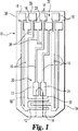
図1〜3を参照して、電気化学センサー10には、複合電極システムを設けることができる。例えば、図1から、そのようなセンサーの1つの実施態様における対向電極および作用電極12,14(以後、それぞれ「CE」および「WE」とする)の各々が、電極12,14を計器(示していない)に電気的接続をさせるために、それぞれ独立したコンタクトパッド18を持った2つのトレースリード16を含む。サンプル充足電極20、例えばサンプル充足対向電極22およびサンプル充足作用電極24(以下、それぞれ、「SSCE」および「SSWE」とする)を設けてもよい。さらに、補助トレースリード26およびそれらの各々のコンタクト28を、センサー10上に設けられた1つ以上の電極12,14に対して、トレースリード16と電気的接続をして設けてもよい。これらの部品の各々に対する目的および構成は、出願人には知られているが、現在の開示に対して関係がない。結果として、本発明に関係するもの以外、種々の電極部品の特定の構成および目的に関する議論を、これ以上ここでは記述しないものとする。
Referring to FIGS. 1-3, the
相対的に小さなセンサー10上に設けられた複合電極システムは、ある空間的制約を生じる。例えば、図1に示されたように、1つの実施態様におけるコンタクトパッド18,28は、少なくとも2つの横方向の列に交互にずらして配置されている。この交互構造における横方向に隣接するコンタクトパッドの各々は、電極システム中に設けられた他のトレースリード毎に関係している。かくして、隣接トレースリードは、横方向に隣接するコンタクトパッド中には伸びない。例えば、WE14用のトレースリード16は、SSWE24用のトレースリード16に隣接しているが、WE14用のコンタクトパッド18は、SSCE22用コンタクトパッド18に対して横方向に隣接しているが、SSWE24用のコンタクトパッド18は、片側でSSCE22用のまた他の側ではWE12用のトレースリード16に対して横方向に隣接している。
A composite electrode system provided on a relatively
特別の電極システムデザイン(例えば、図1に示されているように)による補助トレースリード26の接続を除き、またWEおよびCE14,12それぞれの2つのトレースリードを除き、電極システムの構成要素は、互いに電気的に一般的に分離されるように意図されている。そのような分離された電極対のコンタクトパッドにおいて、電位または他の電気的作用を印加するためにセンサーが挿入される計器を用い、また危機的に対になった電極にわたって、電流、電位または抵抗などの電気的接続性を示す電気的作用を検出するかまたは測定することにより、そのようなシステム中の電気的分離を確保することが、身近な2重安全装置になる。電気的分離は、絶対的なものとするか(例えば、無限抵抗または電流ゼロ)または、主観的にあらかじめ決定されるべきである(例えば、閾値最小抵抗、または閾値最大電流)。(本開示および特許請求の範囲の目的のために、「測定」という用語は、接続性を指示する電気的作用の検出のみならず、その定量(所定の閾値に対する比較のために)に言及するために意図され、また使用される。電気的分離が、絶対的であることを望むか、または許諾し得る閾値を受けるかどうかは、発明を実行する人の判断力内であり、また発明の範囲の制限ではない。)電位または他の電気的作用を印加した後、もし電気的分離が確認できなければ、または点検できなければ、エラーメッセージを提供しかつ該センサーの使用は、許諾されない。 Special electrode system design (e.g., as shown in FIG. 1) except for the connection of auxiliary trace leads 26 by, also except WE and CE14,12 each of the two traces lead, the components of the electrode system Are intended to be generally electrically separated from one another. In the contact pads of such separate electrode pairs, over have use the instrument sensor is inserted in order to apply a potential or other electrical effect, also became critical paired electrodes, current, potential or Ensuring electrical isolation in such systems by detecting or measuring electrical effects that indicate electrical connectivity, such as resistance, becomes a familiar dual safety device. Electrical isolation, the absolute ones and to Luke (e.g., infinite resistance or current zero) or should be subjectively predetermined (e.g., or a threshold maximum current threshold minimum resistance). (For the purposes of this disclosure and the claims, the term “measurement” refers not only to the detection of electrical effects that indicate connectivity, but also to its quantification (for comparison to a predetermined threshold). is intended for, and Ru are used. electrical isolation, whether receiving the threshold value may desire or permission to be absolute, it is in the judgment of the person performing the invention, also of the invention It is not a range limitation ) After applying a potential or other electrical action, if electrical separation cannot be confirmed or checked , an error message is provided and use of the sensor is not permitted.
図1などのある電極システムの複合性により、またはそのような電極システムが使用されるように意図される計器の所定のデザインおよび方法論により、電気的分離をするように意図される電極コンタクトパッドの各々および各対毎に対して2重安全装置を行うための計器を提供すること、または計器を変更することは困難であり、またはコスト面から効果のないものになろう。さらに、SSCE22およびSSWE24、またはSSWE24およびWE14などの隣接するトレースリード16を持った電極が互いにチェックされるならば、SSCE22およびWE14のトレースリード間に一般的に置かれているSSWE24のコンタクトパッドおよびトレースリードなど、該システムの構成要素が介在することにより、望ましからぬ短絡を検知し損なうことはないだろう。このようにして、計器−センサーシステムは、全ての可能性のある2重安全モードを明らかにするためのある戦略的2重安全チェックに依存している。 Due to the composite nature of certain electrode systems, such as FIG. 1, or due to the predetermined design and methodology of the instrument for which such an electrode system is intended to be used, an electrode contact pad intended for electrical isolation. providing an instrument for performing a double safety device for each and every pair, or it is difficult to change the instrument, or would ineffective in terms of cost. In addition, if electrodes with adjacent trace leads 16 such as SSCE22 and SSWE24, or SSWE24 and WE14 are checked against each other, the contact pads and traces of SSWE24 typically placed between the trace leads of SSCE22 and WE14 lead, etc., by components of the system is interposed, it will never fail to detect a short circuit bran Nozomu Mashikara. In this way, the instrument-sensor system relies on some strategic double safety check to reveal all possible dual safety modes.
電極の相対的位置がそのような短絡を困難にさせているから、このようなチェックがされない電極間に短絡が起きる可能性は、おそらく高くはないが残っている。例えば、図1のセンサーに対して、SSCE22およびWE14は、SSWE24のコンタクトパッドおよびトレースリードが介在するためにチェックされないままであり、またSSWE24は、SSCE22およびWE14からの分離用の計器により別途チェックされる。しかし、SSWE24用コンタクトパッドの上、かつSSCE22およびWE14用のコンタクトパッド間の空間30は、開いたままである。製造欠陥などの種々の理由により、SSCE22およびWE14は、この空き空間30を横切って互いに短絡し得るという可能性が残っている。同様に、空きトレイル32は、SSCE22と、WE14のトレースリードとの間でセンサー10のサンプル経路端34で同定できる。
Since the relative positions of the electrodes which makes it difficult to such short, a short circuit can occur between such check does not have the electrodes remain probably is not high. For example, with respect to the
これらの位置30,32のいずれかを横切って起こる望ましくない短絡回路が、ありそうでないのにもかかわらず、それが不可能でないという事実は、計器により与えられる検体測定結果の精度に関して、重大な問題点を提示する。以上考察したように、サンプル経路36中に暴露される電極に対して、WE14が短絡し、その結果、他の電極がサンプル流体(示されていない)に接触すると、実際の作用は、WE14の表面積が、他の電極の暴露された表面積の量により増加するということである。従って、測定される電流は増加し、それがWE14に対する一定の表面積に依存している計算に対して、高いバイアスを提供することになる。
The fact that an undesired short circuit that occurs across either of these
図1のセンサーの構成から、SSWE24およびSSCE22が、サンプル充足検出機能の目的のために、サンプル経路36中に含まれるから、SSWE24またはSSCE22のいずれかが、WE14の一部に短絡すると、このことが起こり得る。相対的に簡単な計器セットアップを維持するために、計器2重安全チェックは、SSCE22に対してSSWE24をチェックし(サンプル充足検出機能が正しく働くために)またWE14に対してSSWE24をチェックする(それらが最も隣接しかつ望ましくない短絡に直面しそうであるため)。しかし、以上指摘したように、コンタクトパッド端38における空き空間30およびサンプル経路端34における空きトレイル32を横切って、SSCE22〜WE14への短絡のわずかな可能性は残っている。
From the sensor configuration Figure 1, SSWE24 and SSCE22 is, for the purposes of sample sufficiency detection function, because contained in the
ここで図2および図3を参照して、電極のある態様のサイズおよび/または形状は、この可能性を避けるために形成してもよい。図2から、SSWE24のコンタクトパッドには、空き空間30を阻止するために、センサー10のコンタクトパッド端38に向けた延長部40を設けることができる。結果として、空き領域30を横切る短絡の何らかの要因があると、空間制約のために2重安全装置が設けられるSSWE24とWE14の間の短絡が誘導されるであろう。さもなければ、たとえ短絡が全空き空間30を横切って広がらないとしても、SSWE24のコンタクトパッドからの延長40が、空間30における可能な短絡が両方に起こらないとしても、SSCE22とSSWE24の間、またはSSWE24とWE14の間のいずれかに少なくとも短絡を生じさせることを確実にする。
Referring now to FIGS. 2 and 3, the size and / or shape of certain aspects of the electrodes may be formed to avoid this possibility. From Figure 2, the contact pads SSWE24, can be to prevent the
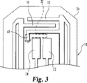
同様に、図3から、空きトレイル32は、トレイル中に伸びているCEの部分42によって、阻止されよう。結果として、他の場合には空きトレイル32を横切る短絡の何らかの原因が、すでに2重安全装置が設けられているCE12およびWE14間の短絡を誘導することになる。
Similarly, from FIG. 3, the
指摘したように、サンプル経路36中でデザインにより暴露される他の電極とWE14の間の望ましくない短絡の結果は、WE14に対する増加した有効表面積により生じる測定結果に対して、高いバイアスとなる。図4〜7を参照して、本発明の他の実施態様は、該生じる高いバイアスを、受け入れ可能なレベルに少なくとも最小化する。図4は、センサー10のサンプル経路端34の従来技術の構造を示しており、そこでは、SSCE22およびSSWE24が、その点まで経路を満たす流体サンプル(示されていない)を検出する目的で、経路36中に暴露されたCE12およびWE14の部分から下流に向けて、サンプル経路36中に暴露される。図4において、SSCE22およびSSWE24の各々の暴露された表面積は、WE14の暴露された表面積未満であるが、暴露されたWE14の約50%より遥かに上である。このようにして、SSCE22およびSSWE24のいずれかとWE14との間の短絡は、有効表面積を、少なくとも約60〜70%またはそれ以上増加させる。
As pointed out, the result of an undesired short between another electrode exposed by the design in the
この増加の望ましくない影響を最小にするために、本発明の実施態様は、サンプル経路36中のSSCE22およびSSWE24の暴露された表面積を、サンプル経路36中のWE14の暴露された表面積の約50%以下に制限する。他の実施態様においては、サンプル経路36中のSSCE22およびSSWE24の暴露された表面積を、サンプル経路36中のWE14の暴露された表面積の約10%以下に制限する。
In order to minimize the undesirable effects of this increase, embodiments of the present invention reduce the exposed surface area of
SSCE22およびSSWE24の削減された表面積に対する種々の構成は、それらの暴露された部分に対する種々のサイズおよび/または形状を含めて、実行することができる。例えば、図5中において(スケールまで示されていない)、SSCE22およびSSWE24のトレースリードは、サンプル経路36をまたぐように、センサー10上を下方に伸びており、またそれらが、横方向に一直線に配列されるように向かい合った両端部から垂直にそこに伸びている。そのような実施態様において、電極22,24は、サンプル経路内の暴露された表面積を最小にするために、部分的にのみ経路36中に伸びる。
Various configurations for the reduced surface area of
図6(スケールまで示されていない)の実施態様において、SSCE22およびSSWE24のトレースリードは、同様に経路36をまたいでセンサー10上を下方に伸び、またその中に垂直に伸びるが、各電極22,24が、実質的に経路36を横切って伸びるように、直線的にオフセットする。そのような実施態様において、電極22,24は、サンプル経路36内の暴露された表面積を最小にするために、典型的にはより細く(より薄く)なる。
In the embodiment of FIG. 6 (not shown to scale), SSCE22 and SSWE24 trace leads are likewise extends down
図7(スケールまで示されていない)の実施態様において、SSCE22およびSSWE24のトレースリードは、センサー10の下において、一般的に直接、サンプル経路36の端部44内に、CE12の短絡ポイントに向かって伸びる。そのような実施態様において、電極22,24は、サンプル経路36内の暴露された表面積を最小にするために、再びより細く(より薄く)なる。
In the embodiment of FIG. 7 (not shown to scale), the trace leads of
センサー上の電極構造にふさわしい先の実施態様に加えて、さらに本発明は、そのようなセンサーを受け取りかつ電気的に接続するために形成された計器を用いたセンサーの使用に関する方法の実施態様を説明する。該方法に関する工程は、本明細書中に開示されており、また特許請求の範囲に引用されている。 In addition to the previous embodiment suitable for the electrode structure on the sensor, the present invention further provides an embodiment of a method relating to the use of the sensor with a meter formed to receive and electrically connect such a sensor. explain. The steps relating to the method are disclosed herein and are cited in the claims.
本発明を詳細に、またその特定の実施態様を参照し記述したので、特許請求の範囲に定められた本発明の範囲を逸脱することなく、改変および変更が可能であることは明白である。さらに具体的には、本発明のいくつかの態様は、好ましい、または特別の利点としてここにおいて確認されるけれども、本発明は、発明のこれらの態様に必ずしも限定されるものではないことが意図されている。 Having described the invention in detail and with reference to specific embodiments thereof, it will be apparent that modifications and variations are possible without departing from the scope of the invention as defined in the claims. More specifically, although some aspects of the invention are identified herein as preferred or special advantages, it is intended that the invention is not necessarily limited to these aspects of the invention. ing.
Claims (4)
該システムは、電気化学センサーおよび計器を備え、
該センサーは、前記計器に受け取られ、また電気的に接続されるために適用され、
該センサーは、作用電極、複数の他の電極、およびサンプル受け取り領域を有する同一平面電極システムを備え、
該他の電極の第1電極および第2電極は、そのそれぞれの一方の電極および該作用電極から電気的に分離されるように形成され、
該第1電極は、少なくともその一部が該サンプル受け取り領域内に暴露される遠心端を含み、
該第2電極は、その一方端に延長部を含み、該延長部は、前記サンプル受け取り領域内で露出した部分を有しておらず、かつ該第1電極と該一方端に近い該作用電極との間で該センサー上の空間またはトレイルを遮断し、前記延長部が、前記第1電極と前記作用電極との間の直接の短絡を防止し、
該延長部は、該空間またはトレイル中に起きる、該第1電極と該作用電極との間の電気的短絡に対する電気的接続性のために形成され、該電気的短絡は、該センサーの望ましい分離された電極構造にもかかわらず生じる、該第1電極と作用電極との間のいかなる電気的接続性も含み、
該計器は、該センサーが該計器に電気的に接続され、点検されるときに、作用電極と第2電極との間、および第1電極と第2電極との間に電流または電圧を印加し、
前記計器は、作用電極と第1電極との間には、電流または電圧を印加せずに、
電気的接続性を示す電気的作用を検出または測定することにより、該作用電極と該第2電極との間および該第1電極と該第2電極との間の電気的分離性とを点検する
ことを特徴とするシステム。A system for controlling the effects of defects due to a short circuit of a coplanar electrochemical sensor for measuring the concentration of an analyte in a sample fluid comprising:
The system comprises an electrochemical sensor and instrument,
The sensor is applied to be received and electrically connected to the instrument,
The sensor comprises a coplanar electrode system having a working electrode, a plurality of other electrodes, and a sample receiving area;
The first electrode and the second electrode of the other electrode are formed so as to be electrically separated from the respective one electrode and the working electrode,
The first electrode includes a distal end at least a portion of which is exposed in the sample receiving area;
The second electrode includes an extension at one end thereof, the extension does not have an exposed portion in the sample receiving region, and the working electrode is close to the first electrode and the one end. Block the space or trail on the sensor between, and the extension prevents a direct short circuit between the first electrode and the working electrode;
The extension is formed for electrical connectivity to an electrical short between the first electrode and the working electrode that occurs in the space or trail, the electrical short being a desired separation of the sensor. resulting despite the electrode structure, any electrical connection also seen free between the first electrode and the working electrode,
The instrument applies a current or voltage between the working electrode and the second electrode and between the first electrode and the second electrode when the sensor is electrically connected to the instrument and inspected. ,
The instrument does not apply a current or voltage between the working electrode and the first electrode,
Checking electrical isolation between the working electrode and the second electrode and between the first electrode and the second electrode by detecting or measuring an electrical effect indicative of electrical connectivity <br/> A system characterized by this.
該システムは、電気化学センサーおよび計器を備え、The system comprises an electrochemical sensor and instrument,
該センサーは、前記計器に受け取られ、また電気的に接続されるために適用され、The sensor is applied to be received and electrically connected to the instrument,
該センサーは、作用電極、複数の他の電極、およびサンプル受け取り領域を有する同一平面電極システムを備え、The sensor comprises a coplanar electrode system having a working electrode, a plurality of other electrodes, and a sample receiving area;
該他の電極の第1電極および第2電極は、そのそれぞれの一方の電極および該作用電極から電気的に分離されるように形成され、The first electrode and the second electrode of the other electrode are formed so as to be electrically separated from the respective one electrode and the working electrode,
該第1電極は、少なくともその一部が該サンプル受け取り領域内に暴露される遠心端を含み、The first electrode includes a distal end at least a portion of which is exposed in the sample receiving area;
該第2電極は、その一方端に延長部を含み、該延長部は、前記サンプル受け取り領域内で露出した部分を有しておらず、かつ該第1電極と該一方端に近い該作用電極との間で該センサー上の空間またはトレイルを遮断し、前記延長部が、前記第1電極と前記作用電極との間の直接の短絡を防止し、The second electrode includes an extension at one end thereof, the extension does not have an exposed portion in the sample receiving region, and the working electrode is close to the first electrode and the one end. Block the space or trail on the sensor between, and the extension prevents a direct short circuit between the first electrode and the working electrode;
該延長部は、該空間またはトレイル中に起きる、該第1電極と該作用電極との間の電気的短絡に対する電気的接続性のために形成され、該電気的短絡は、該センサーの望ましい分離された電極構造にもかかわらず生じる、該第1電極と作用電極との間のいかなる電気的接続性も含み、The extension is formed for electrical connectivity to an electrical short between the first electrode and the working electrode that occurs in the space or trail, the electrical short being a desired separation of the sensor. Including any electrical connectivity between the first electrode and the working electrode that occurs despite the structured electrode structure;
該計器は、該センサーが該計器に電気的に接続され、点検されるときに、該作用電極と第2電極との間、または第1電極と第2電極との間に電流または電圧を印加し、作用電極と第1電極との間には、電流または電圧を印加せずに、The instrument applies a current or voltage between the working electrode and the second electrode or between the first electrode and the second electrode when the sensor is electrically connected to the instrument and inspected. And without applying a current or voltage between the working electrode and the first electrode,
電気的接続性を示す電気的作用を検出または測定することにより、By detecting or measuring electrical effects that indicate electrical connectivity,
該作用電極と該第2電極との間または該第1電極と該第2電極との間の電気的分離性を点検することを特徴とするシステム。A system for checking electrical separation between the working electrode and the second electrode or between the first electrode and the second electrode.
該方法は、センサー基板上に作用電極と少なくとも第1電極および第2電極を設ける工程と、
該センサーを受け取りかつ該センサーと電気的に接続するように形成された計器中に、該センサーを挿入する工程と、
該作用電極と該第2電極との間の電気的接続性を前記計器によって測定するために、作用電極と第1電極との間には、電流または電圧を印加せずに、作用電極と第2電極との間、および/または第1電極と第2電極との間に、電流または電圧を印加する工程と、
該第1電極と第2電極との間の電気的接続性を前記計器によって測定するために、前記電流または電圧を印加する工程により、該計器が、電気的接続性を示す電気的作用を検出または測定することにより、該作用電極と該第2電極との間および/または該第1電極と該第2電極との間の電気的分離性とを点検する工程と、
該作用電極と該第2電極との間、または該第1電極と第2電極との間で電気的接続性が測定される場合に、該計器上にエラーメッセージを表示する工程とを含み、
該作用電極と該第1電極の少なくとも一部が、該センサーのサンプル受け取り領域中に暴露され、前記第2電極が、該作用電極と該一方端の近くの該第1電極との間に実質的に伸びるように形成された延長部を持つように設けられ、該第1電極と、該第2電極と作用電極の各々が、互いに電気的に分離され、
該第1電極と該作用電極の間のいかなる電気的接続性も、該第1電極と該一方端に近い第2電極との間の電気的接続性を生じ、
該延長部は、前記サンプル受け取り領域内で露出した部分を有しておらず、かつ該第1電極と該一方端に近い該作用電極との間で該センサー上の空間またはトレイルを遮断し、前記延長部が、前記第1電極と前記作用電極との間の直接の短絡を防止することを特徴とする方法。A method for indirectly checking electrical isolation between non-adjacent electrodes of an electrochemical sensor having a coplanar electrode system, comprising:
The method includes Ru provided with at least first electrode and the second electrode and the working electrode sensors on a substrate,
Inserting the sensor into an instrument configured to receive and electrically connect to the sensor;
In order to measure the electrical connectivity between the working electrode and the second electrode by the instrument , no current or voltage is applied between the working electrode and the first electrode, Applying a current or voltage between the two electrodes and / or between the first electrode and the second electrode ;
In order to measure the electrical connectivity between the first electrode and the second electrode by the instrument, the instrument detects an electrical effect indicating electrical connectivity by applying the current or voltage. Or checking the electrical isolation between the working electrode and the second electrode and / or between the first electrode and the second electrode by measuring ;
Displaying an error message on the instrument when electrical connectivity is measured between the working electrode and the second electrode or between the first electrode and the second electrode;
The working electrode and at least a portion of the first electrode are exposed in a sample receiving area of the sensor, and the second electrode is substantially between the working electrode and the first electrode near the one end. Each of the first electrode, the second electrode, and the working electrode is electrically separated from each other.
Any electrical connectivity between the first electrode and the working electrode results in electrical connectivity between the first electrode and the second electrode near the one end ,
The extension does not have an exposed portion in the sample receiving area and blocks a space or trail on the sensor between the first electrode and the working electrode near the one end; the extension portion is wherein that you avoid direct short circuit between the working electrode and the first electrode.
Applications Claiming Priority (3)
| Application Number | Priority Date | Filing Date | Title |
|---|---|---|---|
| US69028405P | 2005-06-14 | 2005-06-14 | |
| US60/690,284 | 2005-06-14 | ||
| PCT/EP2006/005611 WO2006133878A2 (en) | 2005-06-14 | 2006-06-12 | Methods and devices for controlling the impact of short circuit faults on co-planar electrochemical sensors |
Publications (3)
| Publication Number | Publication Date |
|---|---|
| JP2008544234A JP2008544234A (en) | 2008-12-04 |
| JP2008544234A5 JP2008544234A5 (en) | 2011-06-30 |
| JP4879979B2 true JP4879979B2 (en) | 2012-02-22 |
Family
ID=37027563
Family Applications (1)
| Application Number | Title | Priority Date | Filing Date |
|---|---|---|---|
| JP2008516205A Expired - Fee Related JP4879979B2 (en) | 2005-06-14 | 2006-06-12 | Method and system for controlling the effects of short circuit failure on coplanar electrochemical sensors |
Country Status (7)
| Country | Link |
|---|---|
| US (1) | US7905997B2 (en) |
| EP (1) | EP1893999B1 (en) |
| JP (1) | JP4879979B2 (en) |
| CN (1) | CN101198867B (en) |
| CA (1) | CA2611148C (en) |
| HK (1) | HK1122099A1 (en) |
| WO (1) | WO2006133878A2 (en) |
Families Citing this family (16)
| Publication number | Priority date | Publication date | Assignee | Title |
|---|---|---|---|---|
| US8206565B2 (en) * | 2003-06-20 | 2012-06-26 | Roche Diagnostics Operation, Inc. | System and method for coding information on a biosensor test strip |
| US7645421B2 (en) | 2003-06-20 | 2010-01-12 | Roche Diagnostics Operations, Inc. | System and method for coding information on a biosensor test strip |
| US8058077B2 (en) | 2003-06-20 | 2011-11-15 | Roche Diagnostics Operations, Inc. | Method for coding information on a biosensor test strip |
| US7718439B2 (en) * | 2003-06-20 | 2010-05-18 | Roche Diagnostics Operations, Inc. | System and method for coding information on a biosensor test strip |
| US20080237040A1 (en) * | 2007-03-27 | 2008-10-02 | Paul Wessel | Test strip and monitoring device |
| JP4856009B2 (en) * | 2007-05-31 | 2012-01-18 | グンゼ株式会社 | Biosensor |
| JP4856011B2 (en) * | 2007-06-05 | 2012-01-18 | グンゼ株式会社 | Biosensor |
| JP2010525353A (en) * | 2007-09-05 | 2010-07-22 | ライフスキャン・スコットランド・リミテッド | Strip for electrochemical measurements |
| WO2009057793A1 (en) * | 2007-10-31 | 2009-05-07 | Arkray, Inc. | Analysis tool, analyzer, sample shortage detection method, and sample analysis method |
| JP2010206027A (en) * | 2009-03-04 | 2010-09-16 | Renesas Electronics Corp | Tcp semiconductor device |
| WO2011159315A1 (en) * | 2010-06-18 | 2011-12-22 | Hewlett-Packard Development Company L.P. | Systems and methods for determining electrical connectivity |
| US8888973B2 (en) | 2011-07-29 | 2014-11-18 | Roche Diagnostics Operations, Inc. | Encoded biosensors and methods of manufacture and use thereof |
| WO2017114746A1 (en) * | 2015-12-28 | 2017-07-06 | Lifescan Scotland Limited | Electrochemical-based analytical test strip with electrode voltage sensing connections and hand-held test meter for use therewith |
| CN109580742B (en) * | 2019-01-14 | 2021-07-27 | 三诺生物传感股份有限公司 | Carbon electrode test strip test system |
| WO2021138405A1 (en) | 2019-12-30 | 2021-07-08 | Roche Diabetes Care, Inc. | Temperature compensated biosensors and methods of manufacture and use thereof |
| CN117092183A (en) * | 2022-05-18 | 2023-11-21 | 利多(香港)有限公司 | Biosensor and preparation method thereof |
Citations (5)
| Publication number | Priority date | Publication date | Assignee | Title |
|---|---|---|---|---|
| JPS6488354A (en) * | 1987-07-15 | 1989-04-03 | Stanford Res Inst Int | Surface type microelectronic gas and steam sensor |
| JPH07167812A (en) * | 1993-09-21 | 1995-07-04 | Asulab Sa | Measuring instrument used together with freely attachable/detachable sensor |
| JPH08193969A (en) * | 1994-06-27 | 1996-07-30 | Ciba Corning Diagnostics Corp | Electrochemical sensor |
| JP2004245734A (en) * | 2003-02-14 | 2004-09-02 | Techno Medica Co Ltd | Disposable sensor card for measuring blood component |
| WO2004113910A1 (en) * | 2003-06-20 | 2004-12-29 | Roche Diagnostics Gmbh | Devices and methods relating to electrochemical biosensors |
Family Cites Families (7)
| Publication number | Priority date | Publication date | Assignee | Title |
|---|---|---|---|---|
| JP2752486B2 (en) * | 1989-12-29 | 1998-05-18 | キヤノン株式会社 | INK JET PRINT HEAD, INSPECTION METHOD THEREOF, AND INK JET PRINTING APPARATUS |
| JPH0820412B2 (en) * | 1990-07-20 | 1996-03-04 | 松下電器産業株式会社 | Quantitative analysis method and device using disposable sensor |
| DE4123348A1 (en) * | 1991-07-15 | 1993-01-21 | Boehringer Mannheim Gmbh | ELECTROCHEMICAL ANALYSIS SYSTEM |
| CA2153883C (en) * | 1993-06-08 | 1999-02-09 | Bradley E. White | Biosensing meter which detects proper electrode engagement and distinguishes sample and check strips |
| DE4427363A1 (en) * | 1993-08-03 | 1995-03-09 | A & D Co Ltd | A disposable chemical sensor |
| US7073246B2 (en) * | 1999-10-04 | 2006-07-11 | Roche Diagnostics Operations, Inc. | Method of making a biosensor |
| US6743635B2 (en) * | 2002-04-25 | 2004-06-01 | Home Diagnostics, Inc. | System and methods for blood glucose sensing |
-
2006
- 2006-06-12 CA CA2611148A patent/CA2611148C/en not_active Expired - Fee Related
- 2006-06-12 WO PCT/EP2006/005611 patent/WO2006133878A2/en not_active Application Discontinuation
- 2006-06-12 JP JP2008516205A patent/JP4879979B2/en not_active Expired - Fee Related
- 2006-06-12 EP EP06754300.9A patent/EP1893999B1/en active Active
- 2006-06-12 CN CN2006800210342A patent/CN101198867B/en not_active Expired - Fee Related
- 2006-06-13 US US11/423,797 patent/US7905997B2/en not_active Expired - Fee Related
-
2008
- 2008-12-04 HK HK08113228.9A patent/HK1122099A1/en not_active IP Right Cessation
Patent Citations (5)
| Publication number | Priority date | Publication date | Assignee | Title |
|---|---|---|---|---|
| JPS6488354A (en) * | 1987-07-15 | 1989-04-03 | Stanford Res Inst Int | Surface type microelectronic gas and steam sensor |
| JPH07167812A (en) * | 1993-09-21 | 1995-07-04 | Asulab Sa | Measuring instrument used together with freely attachable/detachable sensor |
| JPH08193969A (en) * | 1994-06-27 | 1996-07-30 | Ciba Corning Diagnostics Corp | Electrochemical sensor |
| JP2004245734A (en) * | 2003-02-14 | 2004-09-02 | Techno Medica Co Ltd | Disposable sensor card for measuring blood component |
| WO2004113910A1 (en) * | 2003-06-20 | 2004-12-29 | Roche Diagnostics Gmbh | Devices and methods relating to electrochemical biosensors |
Also Published As
| Publication number | Publication date |
|---|---|
| HK1122099A1 (en) | 2009-05-08 |
| CA2611148C (en) | 2012-02-14 |
| EP1893999B1 (en) | 2019-09-11 |
| US7905997B2 (en) | 2011-03-15 |
| CN101198867A (en) | 2008-06-11 |
| WO2006133878A2 (en) | 2006-12-21 |
| JP2008544234A (en) | 2008-12-04 |
| EP1893999A2 (en) | 2008-03-05 |
| CN101198867B (en) | 2013-01-02 |
| US20060278538A1 (en) | 2006-12-14 |
| WO2006133878A3 (en) | 2007-05-31 |
| CA2611148A1 (en) | 2006-12-21 |
Similar Documents
| Publication | Publication Date | Title |
|---|---|---|
| JP4879979B2 (en) | Method and system for controlling the effects of short circuit failure on coplanar electrochemical sensors | |
| JP2008544234A5 (en) | ||
| US11137366B2 (en) | Electrode arrangements for test element integrity | |
| KR102143685B1 (en) | Apparatus for measuring electrical conductivity of soil | |
| US11709147B2 (en) | Electrolyte measuring device | |
| CA3061348C (en) | Electrode break detection | |
| CN209043837U (en) | Universal testing piece | |
| JP2017538942A5 (en) | ||
| TWI586333B (en) | A blood volume detecting method and a detecting device using the same | |
| JP6336405B2 (en) | Cross-sectional area change detection device |
Legal Events
| Date | Code | Title | Description |
|---|---|---|---|
| A521 | Written amendment |
Free format text: JAPANESE INTERMEDIATE CODE: A523 Effective date: 20090513 |
|
| A621 | Written request for application examination |
Free format text: JAPANESE INTERMEDIATE CODE: A621 Effective date: 20090513 |
|
| RD03 | Notification of appointment of power of attorney |
Free format text: JAPANESE INTERMEDIATE CODE: A7423 Effective date: 20100525 |
|
| A131 | Notification of reasons for refusal |
Free format text: JAPANESE INTERMEDIATE CODE: A131 Effective date: 20110215 |
|
| A977 | Report on retrieval |
Free format text: JAPANESE INTERMEDIATE CODE: A971007 Effective date: 20110217 |
|
| A524 | Written submission of copy of amendment under section 19 (pct) |
Free format text: JAPANESE INTERMEDIATE CODE: A524 Effective date: 20110513 |
|
| A131 | Notification of reasons for refusal |
Free format text: JAPANESE INTERMEDIATE CODE: A131 Effective date: 20110816 |
|
| A521 | Written amendment |
Free format text: JAPANESE INTERMEDIATE CODE: A523 Effective date: 20111024 |
|
| TRDD | Decision of grant or rejection written | ||
| A01 | Written decision to grant a patent or to grant a registration (utility model) |
Free format text: JAPANESE INTERMEDIATE CODE: A01 Effective date: 20111122 |
|
| A01 | Written decision to grant a patent or to grant a registration (utility model) |
Free format text: JAPANESE INTERMEDIATE CODE: A01 |
|
| A61 | First payment of annual fees (during grant procedure) |
Free format text: JAPANESE INTERMEDIATE CODE: A61 Effective date: 20111130 |
|
| R150 | Certificate of patent or registration of utility model |
Ref document number: 4879979 Country of ref document: JP Free format text: JAPANESE INTERMEDIATE CODE: R150 Free format text: JAPANESE INTERMEDIATE CODE: R150 |
|
| FPAY | Renewal fee payment (event date is renewal date of database) |
Free format text: PAYMENT UNTIL: 20141209 Year of fee payment: 3 |
|
| R250 | Receipt of annual fees |
Free format text: JAPANESE INTERMEDIATE CODE: R250 |
|
| R250 | Receipt of annual fees |
Free format text: JAPANESE INTERMEDIATE CODE: R250 |
|
| R250 | Receipt of annual fees |
Free format text: JAPANESE INTERMEDIATE CODE: R250 |
|
| R250 | Receipt of annual fees |
Free format text: JAPANESE INTERMEDIATE CODE: R250 |
|
| R250 | Receipt of annual fees |
Free format text: JAPANESE INTERMEDIATE CODE: R250 |
|
| LAPS | Cancellation because of no payment of annual fees |