JP4878570B2 - Image reading apparatus and setting method thereof - Google Patents
Image reading apparatus and setting method thereof Download PDFInfo
- Publication number
- JP4878570B2 JP4878570B2 JP2007089517A JP2007089517A JP4878570B2 JP 4878570 B2 JP4878570 B2 JP 4878570B2 JP 2007089517 A JP2007089517 A JP 2007089517A JP 2007089517 A JP2007089517 A JP 2007089517A JP 4878570 B2 JP4878570 B2 JP 4878570B2
- Authority
- JP
- Japan
- Prior art keywords
- line
- sensor
- line sensor
- color
- mtf
- Prior art date
- Legal status (The legal status is an assumption and is not a legal conclusion. Google has not performed a legal analysis and makes no representation as to the accuracy of the status listed.)
- Expired - Fee Related
Links
Images


Classifications
-
- H—ELECTRICITY
- H04—ELECTRIC COMMUNICATION TECHNIQUE
- H04N—PICTORIAL COMMUNICATION, e.g. TELEVISION
- H04N1/00—Scanning, transmission or reproduction of documents or the like, e.g. facsimile transmission; Details thereof
- H04N1/04—Scanning arrangements, i.e. arrangements for the displacement of active reading or reproducing elements relative to the original or reproducing medium, or vice versa
- H04N1/10—Scanning arrangements, i.e. arrangements for the displacement of active reading or reproducing elements relative to the original or reproducing medium, or vice versa using flat picture-bearing surfaces
- H04N1/1013—Scanning arrangements, i.e. arrangements for the displacement of active reading or reproducing elements relative to the original or reproducing medium, or vice versa using flat picture-bearing surfaces with sub-scanning by translatory movement of at least a part of the main-scanning components
- H04N1/1017—Scanning arrangements, i.e. arrangements for the displacement of active reading or reproducing elements relative to the original or reproducing medium, or vice versa using flat picture-bearing surfaces with sub-scanning by translatory movement of at least a part of the main-scanning components the main-scanning components remaining positionally invariant with respect to one another in the sub-scanning direction
-
- H—ELECTRICITY
- H04—ELECTRIC COMMUNICATION TECHNIQUE
- H04N—PICTORIAL COMMUNICATION, e.g. TELEVISION
- H04N1/00—Scanning, transmission or reproduction of documents or the like, e.g. facsimile transmission; Details thereof
- H04N1/024—Details of scanning heads ; Means for illuminating the original
- H04N1/028—Details of scanning heads ; Means for illuminating the original for picture information pick-up
- H04N1/03—Details of scanning heads ; Means for illuminating the original for picture information pick-up with photodetectors arranged in a substantially linear array
-
- H—ELECTRICITY
- H04—ELECTRIC COMMUNICATION TECHNIQUE
- H04N—PICTORIAL COMMUNICATION, e.g. TELEVISION
- H04N1/00—Scanning, transmission or reproduction of documents or the like, e.g. facsimile transmission; Details thereof
- H04N1/04—Scanning arrangements, i.e. arrangements for the displacement of active reading or reproducing elements relative to the original or reproducing medium, or vice versa
- H04N1/0402—Scanning different formats; Scanning with different densities of dots per unit length, e.g. different numbers of dots per inch (dpi); Conversion of scanning standards
- H04N1/0408—Different densities of dots per unit length
-
- H—ELECTRICITY
- H04—ELECTRIC COMMUNICATION TECHNIQUE
- H04N—PICTORIAL COMMUNICATION, e.g. TELEVISION
- H04N1/00—Scanning, transmission or reproduction of documents or the like, e.g. facsimile transmission; Details thereof
- H04N1/04—Scanning arrangements, i.e. arrangements for the displacement of active reading or reproducing elements relative to the original or reproducing medium, or vice versa
- H04N1/10—Scanning arrangements, i.e. arrangements for the displacement of active reading or reproducing elements relative to the original or reproducing medium, or vice versa using flat picture-bearing surfaces
- H04N1/1013—Scanning arrangements, i.e. arrangements for the displacement of active reading or reproducing elements relative to the original or reproducing medium, or vice versa using flat picture-bearing surfaces with sub-scanning by translatory movement of at least a part of the main-scanning components
- H04N1/1039—Movement of the main scanning components
- H04N1/1048—Movement of the main scanning components of a lens or lens arrangement
-
- H—ELECTRICITY
- H04—ELECTRIC COMMUNICATION TECHNIQUE
- H04N—PICTORIAL COMMUNICATION, e.g. TELEVISION
- H04N1/00—Scanning, transmission or reproduction of documents or the like, e.g. facsimile transmission; Details thereof
- H04N1/04—Scanning arrangements, i.e. arrangements for the displacement of active reading or reproducing elements relative to the original or reproducing medium, or vice versa
- H04N1/19—Scanning arrangements, i.e. arrangements for the displacement of active reading or reproducing elements relative to the original or reproducing medium, or vice versa using multi-element arrays
- H04N1/191—Scanning arrangements, i.e. arrangements for the displacement of active reading or reproducing elements relative to the original or reproducing medium, or vice versa using multi-element arrays the array comprising a one-dimensional array, or a combination of one-dimensional arrays, or a substantially one-dimensional array, e.g. an array of staggered elements
- H04N1/192—Simultaneously or substantially simultaneously scanning picture elements on one main scanning line
Landscapes
- Engineering & Computer Science (AREA)
- Multimedia (AREA)
- Signal Processing (AREA)
- Facsimile Scanning Arrangements (AREA)
- Facsimile Heads (AREA)
Description
この発明に係る一実施例は、画像読み取り装置及びその設定方法に関する。この装置及び方法は、スキャナで原稿を光学的に読み取る画像読み取り装置に適用して好適し、また、読み取った画像データに基づいて画像を形成するデジタル複写機などに適用して好適する。 One embodiment according to the present invention relates to an image reading apparatus and a setting method thereof. This apparatus and method are suitable for application to an image reading apparatus that optically reads a document with a scanner, and also suitable for application to a digital copying machine that forms an image based on read image data.
従来はカラー画像読み取り用には、光学センサとしてレッド(RED)、グリーン(GREEN)、ブルー(BLUE)の3ラインで構成された3ラインCCDセンサが採用されてきた。3ラインCCDセンサは、3つのラインセンサの各受光面上にレッド、グリーン、ブルーの色フィルタを配置している。そして、3つのラインセンサが並列に並べた構成である。 Conventionally, a three-line CCD sensor composed of three lines of red (RED), green (GREEN), and blue (BLUE) has been adopted as an optical sensor for reading a color image. In the 3-line CCD sensor, red, green, and blue color filters are arranged on the light receiving surfaces of the three line sensors. And it is the structure which arranged three line sensors in parallel.
また、昨今、4ラインCCDセンサも製品化されてきた。4ラインCCDセンサは、3ラインCCDセンサに加え、モノクロ画像読み取りのためのモノクロ読取り用のラインセンサを有する。3ラインCCDセンサは、それぞれのラインセンサが受光面上に特定波長のみを透過する色フィルタを配置している。これに比べてモノクロ読取り用のラインセンサは、受光面上に色フィルタを配置していない。CCDセンサに関する技術を示す文献として、特開2004-272840, 特開2004-180196, 特開2003-274115がある。 Recently, a 4-line CCD sensor has also been commercialized. The 4-line CCD sensor has a monochrome reading line sensor for reading monochrome images in addition to the 3-line CCD sensor. In the 3-line CCD sensor, each line sensor has a color filter that transmits only a specific wavelength on the light receiving surface. In contrast, a line sensor for monochrome reading has no color filter on the light receiving surface. There are JP-A-2004-272840, JP-A-2004-180196, and JP-A-2003-274115 as literatures showing technologies related to the CCD sensor.
上記の4ラインCCDセンサは、4つのラインセンサが原稿走査方向に間隔を置いて配置されている。このためにすべてのラインセンサが原稿の同一箇所を同時に読取ることができない。また、集光レンズの焦点をすべてのラインセンサに対して、同時に合致させることができない。 In the above four-line CCD sensor, four line sensors are arranged at intervals in the document scanning direction. For this reason, all the line sensors cannot simultaneously read the same portion of the document. In addition, the focus of the condenser lens cannot be made to coincide with all the line sensors at the same time.
このために、4ラインCCDセンサを有する画像読み取り装置では、カラー用RGBのラインセンサで読み込まれる画像のためのピント調整を行った後、モノクロ用のラインセンサで読み込まれる画像のためのピント調整を行っている。そして、モノクロ用のラインセンサで読み込まれる画像のためのピント調整により、カラー用RGBのラインセンサで読み込んだときのピントが外れていた場合は、カラー用RGBのラインセンサで読み込むときのピント調整を再度行っている。このように、カラー/モノクロ双方のピントが、平均的に最適な状態となるような合わせこみ調整を繰り返すことで調整を行っている。 For this reason, an image reading apparatus having a 4-line CCD sensor performs focus adjustment for an image read by a color RGB line sensor, and then performs focus adjustment for an image read by a monochrome line sensor. Is going. If the focus of the image read by the monochrome line sensor is out of focus when read by the color RGB line sensor, adjust the focus when reading by the color RGB line sensor. I have done it again. As described above, the adjustment is performed by repeating the adjustment for adjusting the color / monochrome focus to an optimum state on average.
しかし上記した方法では、再調整の繰り返しによる調整時間の増大と、カラー/モノクロ双方のピントが平均的に最適な位置になるように調整しなければならないことから、最終的には本来レンズが持っている画像性能を犠牲にした調整となっていることにも繋がる。
この発明に係る一実施の形態では、調整作業性がよくて調整時間が短く、かつ、光学センサとしての4ラインCCDセンサのピントが平均的に最良の状態になる画像読み取り装置及びその設定方法を提供することを目的とする。 According to an embodiment of the present invention, an image reading apparatus having a good adjustment workability, a short adjustment time, and the average focus of a four-line CCD sensor as an optical sensor and a setting method thereof are provided. The purpose is to provide.
上記の目的を達成するために、この発明の一面では、基本構成として画素数の異なる複数のラインセンサを有した光学センサと、前記光学センサに光学像を投影する集光レンズと、前記複数のラインセンサのうち、画素数が最も多いラインセンサのMTFが最大値となる状態にして前記集光レンズと前記光学センサとの距離を設定した調整機構とを有する。
ここで、MTF={(Max−Min)/(Max+Min)}×100とし、
Maxはラインペアチャートを読み取った際の白黒コントラストの最大値、Minは白黒コントラストの最小値である。
In order to achieve the above object, according to one aspect of the present invention, an optical sensor having a plurality of line sensors having different numbers of pixels as a basic configuration, a condensing lens that projects an optical image on the optical sensor, Among the line sensors, an adjustment mechanism that sets the distance between the condensing lens and the optical sensor in a state where the MTF of the line sensor having the largest number of pixels has a maximum value .
Here, MTF = {(Max−Min) / (Max + Min)} × 100,
Max is the maximum value of black and white contrast when the line pair chart is read, and Min is the minimum value of black and white contrast.
本実施形態によると、調整作業性がよくて調整時間が短く、かつ、光学センサとしての4ラインCCDセンサのピントが平均的に最良の状態となる。 According to this embodiment, the adjustment workability is good, the adjustment time is short, and the focus of the 4-line CCD sensor as an optical sensor is on average in the best state.
以下、この発明に係る実施の形態を図面を参照しながら説明する。図1にCCDラインセンサを用いた画像入力装置の概略構成を示す。 Embodiments of the present invention will be described below with reference to the drawings. FIG. 1 shows a schematic configuration of an image input apparatus using a CCD line sensor.
画像入力装置であるスキャナは、第1キャリッジ4、第2キャリッジ7、集光レンズ8、CCDセンサ基板10、制御基板11、白基準板13、原稿ガラス14、原稿押さえカバー15と、そしてスキャナ筐体16を有する。
The scanner that is an image input device includes a
第1キャリッジ4は、光源1と、光源1の配光特性の補正を行うリフレクタ2と、第1ミラー3を有する。第2キャリッジ7は、第2ミラー5と第3ミラー6を有する。CCDセンサ基板10は、4ラインCCDセンサ9を実装されている。4ラインCCDセンサ9は、カラー用のR,G,B用のラインセンサ9R、9G、9B(以下カラーラインセンサと称する)と、モノクロ用のラインセンサ9K(以下モノクロラインセンサと称する)を並列に有する。
The
制御基板11は、4ラインCCDセンサ9の制御および各種処理を行うための回路を実装されている。白基準板13は、白色の基準として利用される。原稿ガラス14上に原稿orgが置かれ、原稿押さえカバー15は原稿orgをそれが浮かないように抑える。
A circuit for controlling the 4-
この装置は、4ラインCCDセンサ9に対する集光レンズ8の関係に着目している。まず、図1を用いてスキャナの概略動作を説明する。
This apparatus focuses on the relationship of the
光源1から照射された光は、原稿ガラス14を透過し、原稿orgに照射される。また、光源1から照射される光の配光は一様でなく、原稿org上の照度に配光ムラが生じてしまうため、リフレクタ2からの反射光も原稿orgに照射されることで、原稿org上の配光が一様になっている。
The light emitted from the light source 1 passes through the
原稿orgからの反射光は、第1ミラー3、第2ミラー5、第3ミラー6で反射し、集光レンズ8を透過してCCDセンサ9の受光面に結像する。4ラインCCDセンサ9は、CCDセンサ基板10上に実装され、制御基板11から入力する制御信号により制御される。制御基板11とCCDセンサ基板10は、ハーネス12により接続されている。
Reflected light from the original org is reflected by the
原稿押さえカバー15は、原稿ガラス14上に置かれた原稿orgの読取り面が原稿ガラス14に密着するように押さえつけるものである。
The
4ラインCCDセンサ9から出力されるアナログ信号は、各光電変換部の変換効率のばらつきによる高周波歪と、集光レンズ8を用いた縮小光学系であることに起因する収差からなる低周波歪を含んでいる。このために、上記アナログ信号の正規化補正を行うため基準となるデータが必要となる。図1では、その基準データは、白基準板13を読取った際の画像データとする。
The analog signal output from the 4-
従来、4ラインCCDセンサを有する画像読み取り装置(又はスキャナ)では、RGB及びモノクロ用ラインセンサが全て同じ画素数(解像度)を持ち、そのラインセンサで読み込まれた画像の合成にて画像が形成されることから、それぞれのラインセンサに結像する全て条件を最良位置にする必要があった。 Conventionally, in an image reading apparatus (or scanner) having a 4-line CCD sensor, the RGB and monochrome line sensors all have the same number of pixels (resolution), and an image is formed by combining the images read by the line sensor. Therefore, it is necessary to set all the conditions for image formation on each line sensor to the best position.
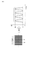
図2−図5A,図5Bを参照して従来のピント調整方法に関する説明を行なう。ピント調整時は、図2に示すようなラインペア(解像)チャートが用いられる。ラインペアチャートは、黒と白のストライプ模様である。チャートラインペア(解像)チャートをCCDセンサ9が読み取る。そして、読み取り信号から得られる正弦波の振幅が観察される。CCDセンサ9と集光レンズ8との距離が微調整され、正弦波の振幅が最大になるようにCCDセンサ9の位置が調整される。
A conventional focus adjustment method will be described with reference to FIGS. 2 to 5A and 5B. At the time of focus adjustment, a line pair (resolution) chart as shown in FIG. 2 is used. The line pair chart is a black and white stripe pattern. The
正弦波の振幅が最大となるということは、白黒のコントラストが大きいということになり、そのレベルを数値化して表現したものをMTF(Modulation Transfer Function)と呼んでいる。 The maximum amplitude of the sine wave means that the contrast between black and white is large, and the level expressed numerically is called MTF (Modulation Transfer Function).
MTFは次式にて表される。 MTF is expressed by the following equation.
MTF[%]={(Max−Min)/(Max+Min)}×100
(コントラストのMax、Minは図2参照)
MTF [%] = {(Max−Min) / (Max + Min)} × 100
(See Fig. 2 for Max and Min of contrast)
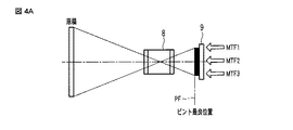
レンズの持つ結像性能は、図3Aに示すようなレンズ8とCCDセンサ9との位置関係で決まり、そして、図3Bに示すように、ピント最良位置でMTFが最大となるようなカーブ(MTFカーブ)を示す。P0がピント最良位置であり、P1はピントがぼけた位置である。
The imaging performance of the lens is determined by the positional relationship between the
4ラインセンサ全てのMTFを最大となるようCCDセンサの位置を調整するのであるが、レンズの持つ結像性能及びCCDセンサ自体のチップの反りの影響もあり、全てが同一の位置に調整することはできない。 The position of the CCD sensor is adjusted so that the MTFs of all four line sensors are maximized. However, there is an influence of the imaging performance of the lens and the warpage of the chip of the CCD sensor itself. I can't.
そのため、まず図4Aと、図4Bに示すよう、ラインセンサ(例えばRのラインセンサ)のライン方向のそれぞれの結像場所(像高)毎に示すMTF1、MTF2、MTF3、を同時に見ながら、MTF最大の位置が多少犠牲にはなるが、全てのバランスが最も良い位置(調整完了位置PF1)に調整している。 Therefore, first, as shown in FIG. 4A and FIG. 4B, while simultaneously viewing MTF1, MTF2, and MTF3 shown for each imaging position (image height) in the line direction of the line sensor (for example, R line sensor), Although the maximum position is somewhat sacrificed, all the balances are adjusted to the best position (adjustment completion position PF1).
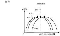
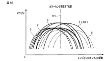
次に、今度は、特にカラー用の3つのラインセンサでは、センサが3つ並んでいるため、RGB全てのMTFが最もバランス良くなるように調整を行っている。即ち、図5Aに示すように、RのラインセンサのMTF(太い実線R)、GのラインセンサのMTF(太い点線G)、BのラインセンサのMTF(細かい点線B)、を測定し、今度は、RGBのバランスが取れた距離を調整完了位置PF2としている。 Next, in particular, in the three line sensors for color, since three sensors are arranged, adjustment is performed so that the MTFs of all RGB are most balanced. That is, as shown in FIG. 5A, the MTF of the R line sensor ( thick solid line R), the MTF of the G line sensor ( thick dotted line G), and the MTF of the B line sensor (fine dotted line B) are measured. Is the adjustment completed position PF2 is a distance in which RGB is balanced.
更に4ラインCCDセンサ9では、カラー用の3つのラインセンサでの調整を行った後に、図5Bに示すようモノクロ用ラインセンサで読み込まれる画像のMTF(実線K)が最大となるよう、手順を踏んで調整を行っている。
Further, in the 4-
しかし、モノクロラインセンサ位置にピントを合わせたが故にカラーラインセンサのピント条件が崩れる時もある。その場合は、再度カラーのラインセンサで画像を読み取り、カラー/モノクロ画像を交互に切り換えながら、カラー/モノクロ双方の画像の振幅が最も高くなるように何度も繰り返して合わせ込み、最終的な調整完了位置PF3を得ている。 However, the focus condition of the color line sensor may be broken because the focus is adjusted to the monochrome line sensor position. In that case, read the image again with the color line sensor, and repeatedly adjust the color / monochrome image repeatedly until the amplitude of both the color / monochrome image becomes the highest. A completion position PF3 is obtained.
しかし、このような方法で調整を行っていることから、再調整の繰り返しによる調整時間の増大と、カラー/モノクロ双方のピントバランスを最良な位置に調整しなければならなくなり、最終的には、本来レンズが持っている結像性能を犠牲にした調整となっていることもあり得る。 However, since the adjustment is performed in this way, the adjustment time increases due to repeated readjustment and the color / monochrome focus balance must be adjusted to the best position. The adjustment may be performed at the expense of the imaging performance inherent in the lens.
上述した技術に対し、本発明では画素数の異なる2つ以上のラインセンサを有するスキャナにおけるピント調整手段を提供する。 In contrast to the above-described technique, the present invention provides a focus adjustment unit in a scanner having two or more line sensors having different numbers of pixels.
図1に戻って、再度、4ラインCCDセンサ9について説明する。この4ラインCCDセンサ9は、画素数の異なる2つ以上のラインセンサの一例であり、表1に示す色フィルタ、解像度を有する。

この表に示す4ラインCCDセンサは、モノクロ画像を600ドット/25.4mm(600dpiと表記されることもある)の高解像度センサで読み取り、カラー画像を300ドット/25.4mm(300dpiと表記されることもある)の低解像度センサで読み込むというものである。
このような構成で成り立っている4ラインCCDセンサの特性を生かしたカラー高解像度化画像処理技術として、次のような技術が可能である。この画像処理は、カラーの低解像度3ラインセンサで読み込まれたカラー画像からは、色情報だけを抽出し、モノクロの高解像度の1つのラインセンサで同時に読み込まれた画像情報を元に合成し、カラーの鮮明で且つ高解像度な画像を作り出すという技術である。
The 4-line CCD sensor shown in this table reads a monochrome image with a high resolution sensor of 600 dots / 25.4 mm (may be described as 600 dpi ) , and reads a color image as 300 dots / 25.4 mm ( 300 dpi ). (It may be read by a low resolution sensor ) .
The following technique is possible as a color high-resolution image processing technique that takes advantage of the characteristics of the 4-line CCD sensor configured as described above. In this image processing, only color information is extracted from a color image read by a color low-resolution three-line sensor, and is synthesized based on the image information read simultaneously by a single monochrome high-resolution line sensor. This is a technique for creating clear and high-resolution images of color.
このような構成で成り立っている4ラインCCDセンサの特性を生かしたカラー高解像度化画像処理技術として、次のような技術が可能である。この画像処理は、カラーの低解像度3ラインセンサで読み込まれたカラー画像からは、色情報だけを抽出し、モノクロの高解像度の1つのラインセンサで同時に読み込まれた画像情報を元に合成し、カラーの鮮明で且つ高解像度な画像を作り出すという技術である。 The following technique is possible as a color high-resolution image processing technique that takes advantage of the characteristics of the 4-line CCD sensor configured as described above. In this image processing, only color information is extracted from a color image read by a color low-resolution three-line sensor, and is synthesized based on the image information read simultaneously by a single monochrome high-resolution line sensor. This is a technique for creating clear and high-resolution images of color.
図6に例を示して説明する。カラー画像は、RGB及びモノクロラインセンサ全ての信号を重ね合わせて作られる。 An example will be described with reference to FIG. A color image is created by superimposing signals of all RGB and monochrome line sensors.
図6のような原稿6aを読み取った際、画像信号6b,6c,6d及び6eのように分解される。カラー画像6b,6c,6dは、画素数の少ない低解像度センサで読み込まれているため画像信号6b,6c,6dのように輪郭情報は粗く読み込まれる。それに対し、画素数の多い高解像度センサで読み込まれたモノクロ画像は、6eのように、より詳細な輪郭情報を持っている。モノクロ画像6eの一部をモノクロ画像6gとして取り出して示し、カラー画像の一部をカラー画像6hを取り出して示している。主走査方向に関しては、モノクロ画像6eの解像度がカラー画像6hよりも高解像度である、副走査方向に関しては、モノクロ画像6eとカラー画像6hの解像度は同じである。
When a
モノクロラインセンサで読み込まれた画像の輪郭情報に、カラーラインセンサで読み込まれた画像の色情報を重ね合わせることで、図6fのような、高解像度なカラー画像を作り出すことが出来る。 By superimposing the color information of the image read by the color line sensor on the contour information of the image read by the monochrome line sensor, a high-resolution color image as shown in FIG. 6f can be created.
この画像処理技術を使用するので、モノクロラインセンサで読み込まれる画像の輪郭情報の取得には、高い精度が要求される。即ち、モノクロラインセンサに対する焦点調整が確実に行わなければならないということになる。一方、カラーラインセンサで読み込まれた画像は、元々画素数の少ない低解像度センサで読み込まれていることから、色情報だけを得られればよく、モノクロラインセンサで読み込まれた画像程のMTF性能は必要ないことになる。この考えかたを本発明は、有効に活用している。 The image processing Runode use the technique, the acquisition of contour information is Ru image read by the monochromatic line sensor, high accuracy is required. That is, the focus adjustment for the monochrome line sensor must be performed reliably. On the other hand, since the image read by the color line sensor is originally read by a low resolution sensor having a small number of pixels, it is sufficient to obtain only color information. It will not be necessary. The present invention makes effective use of this idea.
そこで、本実施例では、カラーの低解像度ラインセンサで読み込まれる画像にはMTF性能を求めない、即ちピント位置調整精度を求めない。そして、モノクロの高解像度ラインセンサで読み込まれる画像に対してはピント調整を行うようにしている。これにより、調整の困難さは軽減し、調整時間が短縮される。また、カラーラインセンサ調整で最良のピント位置を最良な位置を探すが故に、モノクロラインセンサ調整でのピント精度が損なわれることも無くなる。 Therefore, in this embodiment, the MTF performance is not obtained for the image read by the color low-resolution line sensor, that is, the focus position adjustment accuracy is not obtained. Then, focus adjustment is performed on an image read by a monochrome high-resolution line sensor. Thereby, the difficulty of adjustment is reduced and the adjustment time is shortened. Also, since the best focus position is searched for by the color line sensor adjustment, the focus accuracy in the monochrome line sensor adjustment is not lost.
図7A,図7B,図7Cを参照して、本実施例における、ピント調整時の最適な原稿パターンについて、一例を説明する。ピント調整は、前述したように、レンズに対してのラインセンサの位置関係を変えることで調整を行う。 With reference to FIG. 7A, FIG. 7B, and FIG. 7C, an example of the optimal document pattern at the time of focus adjustment in the present embodiment will be described. As described above, the focus adjustment is performed by changing the positional relationship of the line sensor with respect to the lens.
その際、ラインセンサに読み込ませる原稿は、ラインセンサによる解像が発揮されているのかどうかを判別が出来るもので無ければならない。 At that time, the original to be read by the line sensor must be able to determine whether or not the resolution by the line sensor is exhibited.
解像レベルを把握するのに、ラインペアパターンを用いた一例を説明する。 An example using a line pair pattern to grasp the resolution level will be described.
ラインペアパターンは、白色と黒色のラインがある一定の幅でペアをなし、配列されている原稿パターンのことであり、例として上げると、図7Aに示すように、
5ラインペアパターン=白黒の1ペアが1mmの中に5ペアある。
The line pair pattern is a document pattern arranged in a certain width with white and black lines in a pair, and as an example, as shown in FIG.
5 line pair pattern = 5 black / white pairs in 1 mm.
=1/(5*2)
=0.1mm
となり、5ラインペアパターンの線幅は0.1mmということになる。
= 1 / (5 * 2)
= 0.1mm
Thus, the line width of the 5-line pair pattern is 0.1 mm.
本実施例では、600ドット/25.4mmの高解像度ラインセンサで読み込むデータを基にピント調整を行うため、解像できる限界は、
25.4mm/600
=0.0423mm
となり、600ドット/25.4mmの1画素分に相当する最小ラインペアパターンは、
1/(0.0423*2)=11.8ラインペア
となる。よって、0.0846mmの長さ当たり、白黒のペアラインが配列された、11.8ラインペアのチャートを読み込むことが最も精度良くピントの合い具合を判別できる。
In this embodiment, since the focus adjustment is performed based on the data read by the 600 dot / 25.4 mm high resolution line sensor, the resolution limit is
25.4mm / 600
= 0.0423mm
The minimum line pair pattern corresponding to one pixel of 600 dots / 25.4 mm is
1 / (0.0423 * 2) = 11.8 line pair
It becomes. Therefore, it is possible to determine the focus condition with the highest accuracy by reading a chart of 11.8 line pairs in which black and white pair lines are arranged per 0.0846 mm length .
しかし、図7Bに示すように、1画素毎に白黒のラインペアパターンを配列すると、例えば、原稿とラインセンサの位相ズレが0.5画素分だけ生じると、1画素に結像されるデータは、白黒が半分半分で読み込まれることになる。このような場合は、画素としてはグレーとして認識してしまうため、全く解像できていないことになる。 However, as shown in FIG. 7B, if a black and white line pair pattern is arranged for each pixel, for example, if a phase shift between the original and the line sensor occurs by 0.5 pixels, the data imaged on one pixel is Black and white will be read in half. In such a case, since the pixel is recognized as gray, it cannot be resolved at all.
そこで、本実施例では、600ドット/25.4mmの2画素分に相当する最小ラインペアパターンを使用する。 Therefore, in this embodiment, a minimum line pair pattern corresponding to two pixels of 600 dots / 25.4 mm is used.
600ドット/25.4mmの2画素分の最小ラインペアパターンは、図7Cに示すようになる。即ち、
1/((25.4/600)*2*2)=5.9ラインペア
となる。即ち、0.1692mmの長さ当たり、白黒のペアラインが配列された、5.9ラインペアのパターン(或いはチャート)であれば、上述した0.5画素分の位相ズレがあっても、常に1画素に対して白か黒かのどちらかが結像される。つまり、画素ピッチとラインペアチャートの間で、位相ずれにより、図7Bで説明したような真っ黒或いは真っ白の状態が生じない。
The minimum line pair pattern for two pixels of 600 dots / 25.4 mm is as shown in FIG. 7C. That is,
1 / ((25.4 / 600) * 2 * 2) = 5.9 line pairs. That is, if the pattern (or chart) is a 5.9 line pair in which black and white pair lines are arranged per length of 0.1692 mm , even if there is a phase shift of 0.5 pixels as described above, Either white or black is imaged for one pixel . In other words, between the pixel pitch and the line pair chart, the phase shift does not occur completely black or white state as described in FIG. 7B.
但し、一例ではあるが、画素間隔とラインペアパターンを一致させると、データ同士で干渉を起こし、定量的な解像力が測定できないことも考えられる。 However, as an example, if the pixel interval and the line pair pattern are matched, it is conceivable that interference occurs between the data and the quantitative resolution cannot be measured.
その場合の対応としては、ラインセンサが持つ解像度より意図的にラインペアパターンを合わないようにすることも、本実施例の応用として上げられる。 In this case, as an application of the present embodiment, it is possible to intentionally make the line pair pattern not match the resolution of the line sensor.
図8A−図8Cに示すグラフはいずれも、ある一定のラインペアパターンを読み取り、その読み取り信号から得られる正弦波の振幅、即ちMTFレベルに対応する画像である。この画像は、図5Bで説明した調整方法で調整された画像の例である。 Each of the graphs shown in FIGS. 8A to 8C is an image corresponding to an amplitude of a sine wave obtained from a read signal obtained by reading a certain line pair pattern, that is, an MTF level. This image is an example of an image adjusted by the adjustment method described in FIG. 5B.
図8Aはモノクロの高解像度センサで読み込まれた画像、図8Bはカラーの低解像度RGBセンサで読み込まれた画像である。図5Bで調整した調整方法であると、カラーの低解像度RGBセンサからの出力、モノクロの高解像度センサからの出力の両方を調整している。したがってカラー画像データとモノクロ画像データの両方が同程度の犠牲を被る程度に調整している。 FIG. 8A shows an image read by a monochrome high resolution sensor, and FIG. 8B shows an image read by a color low resolution RGB sensor. In the adjustment method adjusted in FIG. 5B, both the output from the color low-resolution RGB sensor and the output from the monochrome high-resolution sensor are adjusted. Therefore, the adjustment is made so that both the color image data and the monochrome image data are subjected to the same sacrifice.
カラー画像データとモノクロ画像データのいずれも同じ振幅を示しているが、図8Bに示すように、低解像度センサの出力の影響が現れており、波形形状が段階的に変化している(粗い)のがわかる。 Although both color image data and monochrome image data show the same amplitude, as shown in FIG. 8B, the influence of the output of the low resolution sensor appears, and the waveform shape changes stepwise (coarse). I understand.
このカラーRGBセンサで読み込まれた画像データをカラー高解像度化処理で補正したものが図8Cである。 FIG. 8C shows the image data read by the color RGB sensor corrected by the color high resolution processing.
図8Aと図8Cの全体振幅は不変であるが、高解像度化処理がかかったことで、振幅波形の形状がなめらかになっているのがわかる。 Although the overall amplitude in FIGS. 8A and 8C is unchanged, it can be seen that the shape of the amplitude waveform is smooth due to the high resolution processing.
図9には、図7Cで説明したラインペアチャートを用いていて、モノクロの高解像度ラインセンサで読み込まれる画像に対してはピント調整を行ったときのMTFを示している。カラーの低解像度ラインセンサで読み込まれる画像にはMTF性能を求めていない。これにより、調整の困難さは軽減し、調整時間が短縮される。この結果、図9に示すように、高解像度のモノクロラインセンサのMTFの最大レベルと、低解像度のカラーラインセンサのMTFの最大レベルとの差は大きい。 FIG. 9 shows the MTF when the line pair chart described in FIG. 7C is used and focus adjustment is performed on an image read by a monochrome high-resolution line sensor. MTF performance is not required for images read by a color low-resolution line sensor. Thereby, the difficulty of adjustment is reduced and the adjustment time is shortened. As a result, as shown in FIG. 9, the difference between the maximum MTF level of the high-resolution monochrome line sensor and the maximum level of the MTF of the low-resolution color line sensor is large.
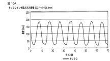
図10A−図10Cに示すグラフはいずれも、ラインペアパターンを読み取り、その読み取り信号から得られる正弦波の振幅、即ちMTFレベルに対応する画像である。 Each of the graphs shown in FIGS. 10A to 10C is an image corresponding to the amplitude of the sine wave, that is, the MTF level obtained from the read signal obtained by reading the line pair pattern.
この例では、モノクロラインセンサで読み込まれた画像を重視してMTFを最良位置に調整し、カラーラインセンサで読み込まれた画像でのピント調整を行わなかった一例である。このために図10Aに示すモノクロラインセンサでの画像に比べ、図10Bに示すカラーラインセンサでのMTFが極端に低いことが分かる。 In this example, the MTF is adjusted to the best position with emphasis on the image read by the monochrome line sensor, and focus adjustment is not performed on the image read by the color line sensor. For this reason, it can be seen that the MTF of the color line sensor shown in FIG. 10B is extremely low compared to the image of the monochrome line sensor shown in FIG. 10A.
この図10Aに示すモノクロデータを基準に、図10Bに示すカラーデータを補正したものが図10Cである。図10Cと図8Cを比べるわかるように、両者とも同等レベルまで補正できている。 FIG. 10C is obtained by correcting the color data shown in FIG. 10B based on the monochrome data shown in FIG. 10A. As can be seen by comparing FIG. 10C and FIG. 8C, both can be corrected to the same level.
同様にして、モノクロラインセンサで読み込まれた画像を主としてピント調整を行い、カラーラインセンサで読み込まれた画像のMTFレベルが高解像度処理により可変された実験結果を、図11に示す。RGBのラインセンサのそれぞれのMTFレベル(11A)は、図6で説明した、高解像度処理が行われることによりMTFレベル(11B)の如く補正されることになる。縦軸は、高解像度化されたときのMTFレベルを示し、横軸はライン数を示す。 Similarly, FIG. 11 shows an experimental result in which focus adjustment is mainly performed on an image read by the monochrome line sensor and the MTF level of the image read by the color line sensor is changed by high resolution processing. Each MTF level (11A) of the RGB line sensors is corrected to the MTF level (11B) by performing the high resolution processing described in FIG. The vertical axis indicates the MTF level when the resolution is increased, and the horizontal axis indicates the number of lines.
このように画素数の異なるモノクロラインセンサとカラーラインセンサを有する4ラインCCDセンサを備えたスキャナにおいて、カラー高解像度化処理を利用することで、モノクロラインセンサで読み込まれた画像にてピント調整を行うようにすれば、調整工数も短縮でき、安価なレンズも使用できることから低コスト化にも繋がる。 In such a scanner equipped with a monochrome line sensor having a different number of pixels and a 4-line CCD sensor having a color line sensor, color adjustment processing is used to adjust the focus on the image read by the monochrome line sensor. If this is done, the adjustment man-hours can be shortened, and an inexpensive lens can be used, leading to a reduction in cost.
上記した方法によれば、カラー用RGBラインセンサと解像度(画素数)の異なるモノクロ用ラインセンサを加えた4ラインCCDセンサを有する画像読み取り装置において、解像度の高いセンサから得られる出力信号を重要視したピント調整を行うことで、調整工数も短縮でき、更にレンズにカラー性能も要求されないことから、安価なレンズも使用でき、低コスト化にも繋がる。 According to the above-described method, in an image reading apparatus having a 4-line CCD sensor in which a monochrome line sensor having a different resolution (number of pixels) from a color RGB line sensor is added, an output signal obtained from a high-resolution sensor is regarded as important. By performing the focus adjustment, adjustment man-hours can be shortened, and color performance is not required for the lens. Therefore, an inexpensive lens can be used, leading to cost reduction.
図12は、ピント調整機構の例を示す。図1と同じ部分には図1と同一符号が付されている。8aは、調整ねじであり、8bは、集光レンズ8のボディーを支持する支持台である。集光レンズ8は、支持台8bにより、Y軸方向へスライドして移動できるように支持されている。8cは集光レンズ8に設けられたねじ挿入部である。Y軸方向の調整ねじ8aが回転されると、集光レンズ8は、Y軸方向へ移動調整される。これにより、上記したピント調整が可能である。
FIG. 12 shows an example of a focus adjustment mechanism. The same parts as those in FIG. 1 are denoted by the same reference numerals as those in FIG.
さらに、CCDセンサ9側にも調整機構を設けてもよい。調整ねじ10a,10bが、CCDセンサ基板10をY軸方向へ貫通して、取り付け基板10cに螺合されている。これにより、CCDセンサ基板10が保持されている。調整ねじ10a、10bが回転されると、CCDセンサ基板10がY軸方向へ移動調整される。また必要に応じてCCDセンサ基板10の傾きなども調整可能である。さらにまた、Y軸方向と直行するX軸方向への調整も可能である。例えば、取り付け基板10bに設けられているX軸方向の調整ねじ10d、10eを回転することにより、取り付け基板10bがX軸方向へ微調整される。取り付け基板10bは、図示しないレールにより支持されている。また、同様に、支持台8bに設けられたX軸方向の調整ねじ8d、8eを回転することにより、支持台8bがX軸方向へ微調整される。支持台8bも図示しないレールにより支持されている。
Further, an adjustment mechanism may be provided on the
図7で説明したラインペアチャートが読み取られたときのモノクロラインセンサ9Kの出力は、カラー画像処理回路を含む制御部120で処理されて、モニタ121に画像として表示される。この画像としては、図9で示したMTFのグラフ、或いは、図10Aで示したようなラインペアチャートの読み取り画像として表示することができる。この装置では、モノクロラインセンサ9Kと、集光レンズ8との間の調整のみで調整作業が完了する。
The output of the
図13には、調整工程を示している。モノクロラインセンサ9Kの水平方向の第1の位置のMTF計測が行なわれる(ステップSA1)。このときは、X軸方向の位置を調整して、第1の位置に固定し、Y軸方向にレンズとモノクロラインセンサとの距離が可変される。次に、同様に、モノクロラインセンサ9Kの水平方向の第2の位置のMTF計測が行なわれる(ステップSA2)。さらに、同様に、モノクロラインセンサ9Kの水平方向の第3の位置のMTF計測が行なわれる(ステップSA3)。この時点で、図9に示したように、3つのモノクロ出力に関するMTFカーブを得ることができる。そして、最もバランスのとれた調整位置が、最終的な調整完了位置PF4として選択される(ステップSA4)。つまり、画素数の異なる2つ以上のラインセンサを有する画像読取装置において、画素数が最も多いラインセンサの解像度が最も高くなるよう光学調整を行うのである。このとき、モノクロラインセンサのライン方向の複数位置で前記距離を可変して複数のMTF1,2,3を測定している。そして、測定された複数のMTFの最大値に対応する各距離(集光レンズとラインセンサ間の距離)の平均的な距離を調整完了位置PF4として選定することで、バランスの取れた調整が可能である。
FIG. 13 shows the adjustment process. MTF measurement is performed at the first horizontal position of the
なお、この発明は、上記実施形態そのままに限定されるものではなく、実施段階ではその要旨を逸脱しない範囲で構成要素を変形して具体化できる。また、上記実施形態に開示されている複数の構成要素の適宜な組み合せにより種々の発明を形成できる。例えば、実施形態に示される全構成要素から幾つかの構成要素を削除してもよい。更に、異なる実施形態に亘る構成要素を適宜組み合せてもよい。 Note that the present invention is not limited to the above-described embodiment as it is, and can be embodied by modifying the constituent elements without departing from the scope of the invention in the implementation stage. Further, various inventions can be formed by appropriately combining a plurality of constituent elements disclosed in the embodiment. For example, some components may be deleted from all the components shown in the embodiment. Furthermore, you may combine suitably the component covering different embodiment.
4…第1キャリッジ、7…第2キャリッジ、8…集光レンズ、8a…調整ねじ、8b…支持台、9…CCDセンサ、10…CCDセンサ基板、10a、10b…調整ねじ。
DESCRIPTION OF
Claims (10)
前記複数のラインセンサを有した光学センサと、
前記光学センサに光学像を投影する集光レンズと、
前記複数のラインセンサのうち、前記モノクロラインセンサのMTFが最大値となる状態にして前記集光レンズと前記光学センサとの距離を設定した調整機構と
を有した画像読み取り装置。
ここで、MTF={(Max−Min)/(Max+Min)}×100とし、
Maxはラインペアチャートを読み取った際の白黒コントラストの最大値、Minは前記白黒コントラストの最小値である。 The highest line sensor number of pixels is set to the monochrome line sensor, a line sensor having a small number of pixels than the number of pixels largest line sensor has a color line sensor, a monochrome image information read by the monochromatic line sensor, wherein An apparatus using a technology for synthesizing color image information read simultaneously with the monochrome image information from a color line sensor ,
An optical sensor having the plurality of line sensors;
A condensing lens that projects an optical image onto the optical sensor;
An image reading apparatus comprising: an adjustment mechanism that sets a distance between the condensing lens and the optical sensor in a state in which an MTF of the monochrome line sensor becomes a maximum value among the plurality of line sensors.
Here, MTF = {(Max−Min) / (Max + Min)} × 100,
Max is the maximum value of the black and white contrast when reading the line pair chart, Min is the minimum value of the black and white contrast.
前記カラーラインセンサは、特定波長のみを透過する色フィルタを有するラインセンサである
請求項1記載の画像読み取り装置。 The monochrome line sensor is a have the line sensors has a color filter that transmits only a specific wavelength,
The color line sensor, an image reading apparatus according to claim 1, wherein the Lula-sensor which have a color filter that transmits only a specific wavelength.
請求項1記載の画像読み取り装置。 2. The adjustment mechanism sets a distance between the condensing lens and the optical sensor in a state where the maximum value of MTF of the monochrome line sensor is higher than the maximum value of MTF of the color line sensor. The image reading apparatus described.
請求項1記載の画像読み取り装置。 The image reading apparatus according to claim 1 , wherein the color line sensor includes three color line sensors each having a color filter that transmits red, green, and blue wavelengths.
前記3つのカラーラインセンサは、それぞれが300ドット/25.4mmの解像度を有する
請求項4記載の画像読み取り装置。 The monochrome line sensor is a need-sensor such has a color filter that transmits only a specific wavelength, and has a resolution of 600 dots 25.4 mm,
The image reading apparatus according to claim 4 , wherein each of the three color line sensors has a resolution of 300 dots / 25.4 mm.
前記複数のラインセンサのうち、前記モノクロラインセンサのMTFを前記モノクロラインセンサのライン方向の複数位置でそれぞれ、前記距離を可変することで複数回測定し、
前記各測定結果得られたMTFの最大値に対応する前記距離の平均的な距離を調整完了位置として設定し、この場合前記調整完了位置の前記MTFの最大値は、残りのラインセンサのMTFの最大値よりも大きい値を設定する画像読み取り装置の設定方法。
ここで、MTF={(Max−Min)/(Max+Min)}×100とし、
Maxはラインペアチャートを読み取った際の白黒コントラストの最大値、Minは前記白黒コントラストの最小値である。 The highest line sensor number of pixels is set to the monochrome line sensor, a line sensor having a small number of pixels than the number of pixels largest line sensor is a color line sensor, a monochrome image information read by the monochromatic line sensor, wherein An apparatus using a technique for combining color image information read simultaneously with the monochrome image information from a color line sensor, the optical sensor having the plurality of line sensors, and a light condensing for projecting an optical image onto the optical sensor A setting method for setting the distance in an apparatus having a lens and an adjustment mechanism for setting a distance between the condenser lens and the optical sensor,
Among the plurality of line sensors, respectively MTF of the monochrome line sensor at a plurality of positions in the line direction of the monochromatic line sensor, and measured a plurality of times by varying the distance,
An average distance of the distances corresponding to the maximum value of the MTF obtained as a result of each measurement is set as an adjustment completion position. In this case, the maximum value of the MTF at the adjustment completion position is the MTF of the remaining line sensors. A method for setting an image reading apparatus that sets a value larger than the maximum value.
Here, MTF = {(Max−Min) / (Max + Min)} × 100,
Max is the maximum value of the black and white contrast when reading the line pair chart, Min is the minimum value of the black and white contrast.
前記モノクロラインセンサと、それぞれレッド、グリーン、ブルーの色フィルタを有する3つの前記カラーラインセンサとを含む4ラインCCDセンサと、前記4ラインCCDセンサに光学像を投影する集光レンズと、前記集光レンズと前記4ラインCCDセンサとの距離を設定する調整機構とを有する装置において、前記距離を設定する設定方法であって、
前記モノクロラインセンサのライン方向の複数位置で前記距離を可変して、前記可変した各距離にてMTFを測定して複数のMTFを得て、
前記複数のMTFの最大値に対応する前記各距離の平均的な距離を調整完了位置として設定し、この場合前記調整完了位置の前記MTFの最大値は、残りのカラーラインセンサのMTFの最大値よりも大きい値を設定する画像読み取り装置の設定方法。
ここで、MTF={(Max−Min)/(Max+Min)}×100とし、
Maxはラインペアチャートを読み取った際の白黒コントラストの最大値、Minは前記白黒コントラストの最小値である。 The highest line sensor number of pixels is set to the monochrome line sensor, a line sensor having a small number of pixels than the number of pixels largest line sensor has a color line sensor, a monochrome image information read by the monochromatic line sensor, wherein An apparatus using a technology for synthesizing color image information read simultaneously with the monochrome image information from a color line sensor ,
Said monochrome line sensor, their respective red, and four line CCD sensor including green, and three of the color line sensor having a blue color filter, a condenser lens for projecting the optical image on the 4-line CCD sensor In an apparatus having an adjustment mechanism for setting a distance between the condenser lens and the 4-line CCD sensor , a setting method for setting the distance,
Said the distance at a plurality of positions in the line direction of the monochromatic line sensor variable, and obtaining a plurality of MTF by measuring the M TF Te in the distances said variable,
Setting the average distance of each distance corresponding to the maximum value before Symbol plurality of MTF as an adjustment completion position, the maximum value of the MTF of this case the adjustment completion position, the maximum MTF of the remaining color line sensor A setting method for an image reading apparatus that sets a value larger than the value.
Here, MTF = {(Max−Min) / (Max + Min)} × 100,
Max is the maximum value of the black and white contrast when reading the line pair chart, Min is the minimum value of the black and white contrast.
Applications Claiming Priority (2)
| Application Number | Priority Date | Filing Date | Title |
|---|---|---|---|
| US11/400,584 | 2006-04-07 | ||
| US11/400,584 US7648071B2 (en) | 2006-04-07 | 2006-04-07 | Apparatus for image reading and method for setting the image reading |
Publications (2)
| Publication Number | Publication Date |
|---|---|
| JP2007282214A JP2007282214A (en) | 2007-10-25 |
| JP4878570B2 true JP4878570B2 (en) | 2012-02-15 |
Family
ID=38574150
Family Applications (1)
| Application Number | Title | Priority Date | Filing Date |
|---|---|---|---|
| JP2007089517A Expired - Fee Related JP4878570B2 (en) | 2006-04-07 | 2007-03-29 | Image reading apparatus and setting method thereof |
Country Status (2)
| Country | Link |
|---|---|
| US (1) | US7648071B2 (en) |
| JP (1) | JP4878570B2 (en) |
Families Citing this family (4)
| Publication number | Priority date | Publication date | Assignee | Title |
|---|---|---|---|---|
| US8089669B2 (en) * | 2007-10-18 | 2012-01-03 | Kabushiki Kaisha Toshiba | Apparatus and control method for image reading, image forming apparatus |
| JP5334902B2 (en) | 2010-03-30 | 2013-11-06 | 大日本スクリーン製造株式会社 | Printing apparatus and camera position adjusting method |
| WO2015159941A1 (en) | 2014-04-16 | 2015-10-22 | グローリー株式会社 | Method and device for removing background of character in color image, method for adjusting installation of line camera, and chart for adjusting installation |
| JP7505644B2 (en) * | 2021-04-27 | 2024-06-25 | 京セラドキュメントソリューションズ株式会社 | Image reading device, image forming device |
Family Cites Families (8)
| Publication number | Priority date | Publication date | Assignee | Title |
|---|---|---|---|---|
| JP2900614B2 (en) * | 1991-01-29 | 1999-06-02 | 富士ゼロックス株式会社 | Position adjustment method of reading sensor in image reading device |
| US5900927A (en) * | 1993-10-13 | 1999-05-04 | Fuji Photo Film Co., Ltd. | Variable target autofocusing and range finder for measuring distance to a subject |
| JP2002171391A (en) * | 2000-12-01 | 2002-06-14 | Canon Inc | IMAGE READING DEVICE, CONTROL METHOD THEREOF, AND MEDIUM PROVIDING CONTROL PROGRAM |
| US6502324B2 (en) * | 2000-12-12 | 2003-01-07 | International Business Machines Corporation | Method of alignment between sheet materials, method of alignment, substrate assembling method and aligning apparatus |
| JP2003075922A (en) * | 2001-09-04 | 2003-03-12 | Konica Corp | Image forming method and apparatus for silver halide color photographic sensitive material |
| JP4557474B2 (en) * | 2001-09-12 | 2010-10-06 | 東芝テック株式会社 | Color signal correction circuit and image reading apparatus |
| JP4796287B2 (en) * | 2004-08-06 | 2011-10-19 | パナソニック株式会社 | Solid-state imaging device |
| JP2006253800A (en) * | 2005-03-08 | 2006-09-21 | Fuji Xerox Co Ltd | Image processing apparatus, image processing method and program |
-
2006
- 2006-04-07 US US11/400,584 patent/US7648071B2/en not_active Expired - Fee Related
-
2007
- 2007-03-29 JP JP2007089517A patent/JP4878570B2/en not_active Expired - Fee Related
Also Published As
| Publication number | Publication date |
|---|---|
| US20070235542A1 (en) | 2007-10-11 |
| JP2007282214A (en) | 2007-10-25 |
| US7648071B2 (en) | 2010-01-19 |
Similar Documents
| Publication | Publication Date | Title |
|---|---|---|
| CN110312125B (en) | Image quality adjustment device, image quality adjustment system, and image quality adjustment method | |
| US8705153B2 (en) | Original reading apparatus reading image from original | |
| JP3710452B2 (en) | Image reading apparatus, data interpolation method, and control program | |
| JP4878570B2 (en) | Image reading apparatus and setting method thereof | |
| US20110075004A1 (en) | Method and apparatus for processing images using black character substitution | |
| US7929806B2 (en) | Image reading apparatus and image reading method | |
| JP2013110582A (en) | Image reading apparatus, image reading method and mtf compensation parameter determining method | |
| US9019405B2 (en) | Method and apparatus for wavelength specific correction of distortion in digital images | |
| JP2006260526A (en) | Image processing apparatus and image processing method | |
| JP5002670B2 (en) | Image processing apparatus and image reading apparatus | |
| JP2005323103A (en) | Image reading device | |
| JP2001197255A (en) | Image reader and image reading method using the device | |
| JP2006340232A (en) | Color image reader | |
| JPH11355513A (en) | Image reading device and copier | |
| JP2005175584A (en) | Image processing system | |
| JP2018117264A (en) | Scanner, scan data production method and scan sensor | |
| JP3178718B2 (en) | Color image reader | |
| JP2010085862A (en) | Image forming device and image reading apparatus | |
| JP2018037925A (en) | Scanner and generation method of image data | |
| CN110521197B (en) | image reading device | |
| JP4217385B2 (en) | Image reading apparatus and method | |
| JPH11177836A (en) | Image processing device | |
| JP2005051387A (en) | Image input apparatus and image processing method | |
| JP2010021727A (en) | Image reading device and control method thereof | |
| JP2022129052A (en) | Imaging apparatus |
Legal Events
| Date | Code | Title | Description |
|---|---|---|---|
| A621 | Written request for application examination |
Free format text: JAPANESE INTERMEDIATE CODE: A621 Effective date: 20091216 |
|
| A977 | Report on retrieval |
Free format text: JAPANESE INTERMEDIATE CODE: A971007 Effective date: 20110502 |
|
| A131 | Notification of reasons for refusal |
Free format text: JAPANESE INTERMEDIATE CODE: A131 Effective date: 20110531 |
|
| A521 | Request for written amendment filed |
Free format text: JAPANESE INTERMEDIATE CODE: A523 Effective date: 20110727 |
|
| A131 | Notification of reasons for refusal |
Free format text: JAPANESE INTERMEDIATE CODE: A131 Effective date: 20110830 |
|
| A521 | Request for written amendment filed |
Free format text: JAPANESE INTERMEDIATE CODE: A523 Effective date: 20111031 |
|
| TRDD | Decision of grant or rejection written | ||
| A01 | Written decision to grant a patent or to grant a registration (utility model) |
Free format text: JAPANESE INTERMEDIATE CODE: A01 Effective date: 20111122 |
|
| A01 | Written decision to grant a patent or to grant a registration (utility model) |
Free format text: JAPANESE INTERMEDIATE CODE: A01 |
|
| A61 | First payment of annual fees (during grant procedure) |
Free format text: JAPANESE INTERMEDIATE CODE: A61 Effective date: 20111128 |
|
| R150 | Certificate of patent or registration of utility model |
Ref document number: 4878570 Country of ref document: JP Free format text: JAPANESE INTERMEDIATE CODE: R150 Free format text: JAPANESE INTERMEDIATE CODE: R150 |
|
| FPAY | Renewal fee payment (event date is renewal date of database) |
Free format text: PAYMENT UNTIL: 20141209 Year of fee payment: 3 |
|
| LAPS | Cancellation because of no payment of annual fees |