JP4876742B2 - Image processing apparatus and image processing program - Google Patents
Image processing apparatus and image processing program Download PDFInfo
- Publication number
- JP4876742B2 JP4876742B2 JP2006188074A JP2006188074A JP4876742B2 JP 4876742 B2 JP4876742 B2 JP 4876742B2 JP 2006188074 A JP2006188074 A JP 2006188074A JP 2006188074 A JP2006188074 A JP 2006188074A JP 4876742 B2 JP4876742 B2 JP 4876742B2
- Authority
- JP
- Japan
- Prior art keywords
- posture
- dimensional
- image
- image processing
- dimensional shape
- Prior art date
- Legal status (The legal status is an assumption and is not a legal conclusion. Google has not performed a legal analysis and makes no representation as to the accuracy of the status listed.)
- Expired - Fee Related
Links
Images


Landscapes
- Image Analysis (AREA)
- Image Processing (AREA)
Description
本発明は、物体の撮像画像から物体の姿勢を推定する画像処理装置及び画像処理プログラムに関するものである。 The present invention relates to an image processing apparatus and an image processing program for estimating the posture of an object from a captured image of the object.
この種の画像処理装置としては、例えば下記非特許文献1に記載されているように、物体の輪郭を用いて姿勢を推定するものが知られている。
しかしながら、上記非特許文献1のように、単に二次元的な情報である物体の輪郭を用いて物体の姿勢を推定すると、物体の誤認識や姿勢の誤推定が起こる場合がある。
However, as in Non-Patent
そこで本発明の目的は、物体の姿勢推定結果の妥当性を的確に判断することができる画像処理装置及び画像処理プログラムを提供することである。 SUMMARY OF THE INVENTION An object of the present invention is to provide an image processing apparatus and an image processing program that can accurately determine the validity of an object posture estimation result.
本発明の画像処理装置は、物体の撮像画像から抽出した物体の輪郭と、複数の視点に応じた物体の輪郭を示すデータが登録されたデータベースとをマッチングすることにより、物体の姿勢を推定する姿勢推定手段と、姿勢推定手段による姿勢推定結果に基づいて物体の三次元形状を三次元座標上に設定する3D推定手段と、三次元計測を行うことにより、物体の三次元形状を検出する検出手段と、3D推定手段によって設定された三次元形状と検出手段によって検出された三次元形状とが重なる領域の大きさに応じ、姿勢推定手段による姿勢推定結果の妥当性を判断する判断手段と、を備えることを特徴とする。 The image processing apparatus of the present invention estimates the posture of an object by matching the contour of the object extracted from the captured image of the object with a database in which data indicating the contour of the object corresponding to a plurality of viewpoints is registered. Attitude estimation means, 3D estimation means for setting the three-dimensional shape of the object on the three- dimensional coordinates based on the attitude estimation result by the attitude estimation means, and detection for detecting the three-dimensional shape of the object by performing three-dimensional measurement means and, depending on the size of the three-dimensional shape and overlap regions detected I by the three-dimensional shape detecting means set by the 3D estimator, decision for determining the validity of the pose estimation result by the posture estimating means And means.
単に、物体の輪郭に基づいて物体の姿勢を推定すると、2次元上における推定誤差は少なくても、三次元上の物体の占める領域としては推定誤差が大きい場合がある。本発明では、物体の輪郭に基づいて推定された姿勢推定結果を利用して物体の三次元形状を三次元座標上に設定し、設定した三次元形状を、三次元計測で検出された三次元形状と照合することによって、物体の姿勢推定結果の妥当性を三次元的に判断する。従って、物体の姿勢推定結果の妥当性を的確に判断することができる。 If the posture of the object is simply estimated based on the contour of the object, the estimation error may be large as a region occupied by the object in three dimensions even if the estimation error in two dimensions is small. In the present invention, to set the three-dimensional shape of the object in the three-dimensional coordinates by using the estimated posture estimation result based on the contour of the object, three-dimensional three-dimensional shape which is set, is detected by the three-dimensional measurement by matching the shape to determine the validity of the object pose estimation results of the three-dimensionally. Therefore, it is possible to accurately determine the validity of the object posture estimation result.
好ましくは、判断手段は、いずれの視点から得られる二次元画像においても同一形状となる領域以外の領域を照合対象領域とし、照合対象領域について、3D推定手段によって設定された三次元形状と検出手段によって検出された三次元形状とが重なる領域の大きさに応じ、姿勢推定結果の妥当性を判断する。この場合、照合対象に適した特徴のある領域を予め設定して、その領域についての照合を行うことで、物体の姿勢推定結果の妥当性をより的確に判断することができる。 Preferably, the determination unit sets a region other than a region having the same shape in a two-dimensional image obtained from any viewpoint as a verification target region, and the three-dimensional shape set by the 3D estimation unit and the detection unit for the verification target region The validity of the posture estimation result is determined in accordance with the size of the region where the three-dimensional shape detected by (1) overlaps . In this case, the validity of the posture estimation result of the object can be determined more accurately by presetting a region having characteristics suitable for the collation target and collating the region.
好ましくは、複数の視点から物体を撮像して得られる複数の画像を重ね合わせた画像において、重なり度合いが所定値より低い領域を照合対象領域に選定する選定手段を更に備える。複数の視点から物体を撮像して得られる複数の画像を重ね合わせた画像において重なり度合いが所定値より低い領域は、その物体において特徴的な領域である。よって、特徴的な領域を照合対象領域に選定することにより、物体の姿勢推定結果の妥当性を十分的確に判断することができる。 Preferably, the image processing apparatus further includes selection means for selecting an area having a degree of overlap lower than a predetermined value as an area to be collated in an image obtained by superimposing a plurality of images obtained by imaging an object from a plurality of viewpoints. A region where the overlapping degree is lower than a predetermined value in an image obtained by superimposing a plurality of images obtained by imaging an object from a plurality of viewpoints is a characteristic region in the object. Therefore, by selecting a characteristic area as a comparison target area, it is possible to sufficiently adequately determine the validity of the object posture estimation result.
本発明の画像処理プログラムは、物体の撮像画像から抽出した物体の輪郭と、複数の視点に応じた物体の輪郭を示すデータが登録されたデータベースとをマッチングすることにより、物体の姿勢を推定する姿勢推定ステップと、姿勢推定ステップにおける姿勢推定結果に基づいて物体の三次元形状を三次元座標上に設定する3D推定ステップと、三次元計測を行うことにより、物体の三次元形状を検出する検出ステップと、3D推定ステップにおいて設定された三次元形状と検出ステップにおいて検出された三次元形状とが重なる領域の大きさに応じ、姿勢推定ステップにおける姿勢推定結果の妥当性を判断する判断ステップと、をコンピュータに実行させることを特徴とする。 The image processing program of the present invention estimates the posture of an object by matching the contour of the object extracted from the captured image of the object with a database in which data indicating the contour of the object corresponding to a plurality of viewpoints is registered. A posture estimation step, a 3D estimation step for setting the three-dimensional shape of the object on a three- dimensional coordinate based on the posture estimation result in the posture estimation step, and a detection for detecting the three-dimensional shape of the object by performing three-dimensional measurement steps and, depending on the size of the three-dimensional shape and overlap region detected have you to set three-dimensional shape as the detection step in 3D estimation step, determination step of determining the validity of the pose estimation result in pose estimation step And making the computer execute.
単に、物体の輪郭に基づいて物体の姿勢を推定すると、2次元上における推定誤差は少なくても、三次元上の物体の占める領域としては推定誤差が大きい場合がある。本発明では、物体の輪郭に基づいて推定された姿勢推定結果を利用して物体の三次元形状を三次元座標上に設定し、設定した三次元形状を、三次元計測で検出された三次元形状と照合することによって、物体の姿勢推定結果の妥当性を三次元的に判断する。従って、物体の姿勢推定結果の妥当性を的確に判断することができる。 If the posture of the object is simply estimated based on the contour of the object, the estimation error may be large as a region occupied by the object in three dimensions even if the estimation error in two dimensions is small. In the present invention, to set the three-dimensional shape of the object in the three-dimensional coordinates by using the estimated posture estimation result based on the contour of the object, three-dimensional three-dimensional shape which is set, is detected by the three-dimensional measurement by matching the shape to determine the validity of the object pose estimation results of the three-dimensionally. Therefore, it is possible to accurately determine the validity of the object posture estimation result.
好ましくは、判断ステップでは、いずれの視点から得られる二次元画像においても同一形状となる領域以外の領域を照合対象領域とし、照合対象領域について、3D推定ステップにおいて設定された三次元形状と検出ステップにおいて検出された三次元形状とが重なる領域の大きさに応じ、姿勢推定結果の妥当性を判断する。この場合、照合対象に適した特徴ある領域を予め設定して、その領域についての照合を行うことで、物体の姿勢推定結果の妥当性をより的確に判断することができる。
Preferably, in the determination step, a region other than a region having the same shape in a two-dimensional image obtained from any viewpoint is set as a collation target region, and the three-dimensional shape set in the 3D estimation step and the detection step for the collation target region The validity of the posture estimation result is determined according to the size of the region where the three-dimensional shape detected in
好ましくは、複数の視点から物体を撮像して得られる複数の画像を重ね合わせた画像において重なり度合いが所定値より低い領域を照合対象領域に選定する選定ステップを更にコンピュータに実行させる。複数の視点から物体を撮像して得られる複数の画像を重ね合わせた画像において重なり度合いが所定値より低い領域は、その物体において特徴的な領域である。よって、特徴的な領域を照合対象領域に選定することにより、物体の姿勢推定結果の妥当性を十分的確に判断することができる。 Preferably, the computer further executes a selection step of selecting an area whose overlapping degree is lower than a predetermined value in an image obtained by superimposing a plurality of images obtained by imaging an object from a plurality of viewpoints. A region where the overlapping degree is lower than a predetermined value in an image obtained by superimposing a plurality of images obtained by imaging an object from a plurality of viewpoints is a characteristic region in the object. Therefore, by selecting a characteristic area as a comparison target area, it is possible to sufficiently adequately determine the validity of the object posture estimation result.
本発明によれば、物体の姿勢推定結果の妥当性を的確に判断することができる。これにより、姿勢推定の推定精度を向上させることができる。 According to the present invention, it is possible to accurately determine the validity of an object posture estimation result. Thereby, the estimation accuracy of posture estimation can be improved.
以下、本発明に係わる画像処理装置及び画像処理プログラムの好適な実施形態について、図面を参照して詳細に説明する。 DESCRIPTION OF EXEMPLARY EMBODIMENTS Hereinafter, preferred embodiments of an image processing apparatus and an image processing program according to the present invention will be described in detail with reference to the drawings.
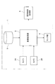
図1は、本発明に係わる画像処理装置の一実施形態の構成を示すブロック図である。本実施形態の画像処理装置1は、例えば認識対象物体として急須やマグカップ等の取っ手付き容器を把持するロボット(図示せず)に搭載されるものである。
FIG. 1 is a block diagram showing a configuration of an embodiment of an image processing apparatus according to the present invention. The
同図において、画像処理装置1は、認識対象物体を撮像するカメラ2A,2Bと、これらのカメラ2A,2Bによる撮像画像を入力し、所定の画像処理を行い、認識対象物体の姿勢を推定する画像処理部3と、この画像処理部3の処理結果を表示するモニタ部4と、画像処理部3による画像処理に使用されるデータベースを蓄積記憶するデータ格納部5とを備えている。
In FIG. 1, an
カメラ2A,2Bは、例えばCCDカメラであり、ロボットの両眼部(図示せず)に設けられている。つまり、カメラ2A,2Bは異なる2つの視点から物体を撮像するように配置されている。
The
画像処理部3は、物体認識処理に特化した専用のハードウェアとして構成されていても良いし、あるいは、パーソナルコンピュータ等の汎用のコンピュータを用い、このコンピュータにソフトウェアとしての画像処理プログラムを実行させても良い。このとき、画像処理プログラムは、例えば、CD−ROM、DVDもしくはROM等の記憶媒体または半導体メモリによって提供される。また、画像処理プログラムは、搬送波に重畳されたコンピュータデータ信号としてネットワークを介して提供されるものであってもよい。
The
また、画像処理部3の処理結果は、把持制御処理部6に送られる。把持制御処理部6は、画像処理部3で推定された認識対象物体の姿勢に基づいて、認識対象物体を把持するようにロボットハンド(図示せず)を制御する。
Further, the processing result of the
図2は、画像処理部3による処理手順の概略を示すフローチャートである。まず、カメラ2A,2Bによる認識対象物体の撮像画像を取得する(ステップ11)。カメラ2A,2Bによる撮像画像の一例を図3に示す。図3(a)は、ロボットの左眼部に配置されたカメラ2Aによる撮像画像(左画像)の概略を示し、図3(b)は、ロボットの右眼部に配置されたカメラ2Bによる撮像画像(右画像)の概略を示している。本実施形態では、例として、認識対象物体を急須としている。
FIG. 2 is a flowchart showing an outline of a processing procedure by the
左画像(図3(a))には、ロボットの左眼部から見た姿勢の急須を示す画像として急須画像31Lが示され、同じく牛乳パックを示す画像として牛乳パック画像32Lが示されている。右画像(図3(b))には、ロボットの右眼部から見た姿勢の急須を示す画像として急須画像31Rが示され、同じく牛乳パックを示す画像として牛乳パック画像32Rが示されている。
In the left image (FIG. 3A), a
続いて、ステップ11で取得した左画像及び右画像について、濃度値が一様とみなせる物体毎の領域に分割する(ステップ12)。また、ステップ12の領域分割処理と並行して、2次元の左画像及び右画像から三次元画像を復元する(ステップ13)。この三次元画像の復元は、例えば両眼視差の考え方を利用して、ある点の左画像及び右画像での位置座標とカメラ2A,2B間の距離とから当該点の奥行きを計算することにより行う。
Subsequently, the left image and the right image acquired in
続いて、ステップ12で領域分割された2次元画像とステップ13で復元された三次元画像とに基づいて、エッジ検出等により物体の輪郭を抽出する(ステップ14)。本実施形態では、認識対象物体である急須の色と同色の領域を示す輪郭を左右画像それぞれから抽出する。
Subsequently, based on the two-dimensional image divided in
続いて、ステップ14で得られた各画像の輪郭の特徴量をそれぞれ抽出する(ステップ15)。輪郭の特徴量としては、輪郭の位置、回転及び大きさに対して不変な不変量を用いる。例えば、撮像画像においては、輪郭に対して互いに平行な複数の接線を描ける場合がある。この場合、接線間の距離は、輪郭の位置、回転及び大きさに対して不変である。そこで、ここでは、不変量として、勾配角度毎の接線間の距離を用いる。
Subsequently, the feature amount of the contour of each image obtained in
続いて、ステップ15で抽出された各画像の輪郭の特徴量を、データ格納部5にデータベースとして記憶されている特徴照合データとマッチングすることにより、各認識対象物体の特徴照合データに対する類似度を算出する(ステップ16)。特徴照合データとしては、複数の視点に応じた認識対象物体の姿勢に関するデータが登録されている。より具体的には、複数の視点に応じた認識対象物体の輪郭を示すデータと、当該輪郭より抽出された特徴量データとが登録されている。
Subsequently, by matching the feature amount of the contour of each image extracted in
ステップ16では、算出した類似度が最も高いデータに対応する物体が、各画像の輪郭によって示される物体に対応すると認識される。本実施形態では、各画像の輪郭は、急須を示すと認識される。なお、マッチング手法としては、例えばDP(Dynamic Programming)マッチング等が採用される。
In
続いて、左画像の輪郭と右画像の輪郭との信頼度を評価し、左右画像のうち信頼度の高いほうの輪郭を含む画像を選択する(ステップ17)。信頼度とは、輪郭を用いて物体の姿勢を推定するにあたって、推定の信頼性を予測するためのものである。具体的には、信頼度として輪郭の複雑度及び特徴量の類似度を用いる。 Subsequently, the reliability of the contour of the left image and the contour of the right image is evaluated, and an image including the contour having the higher reliability of the left and right images is selected (step 17). The reliability is for predicting the reliability of the estimation when estimating the posture of the object using the contour. Specifically, contour complexity and feature similarity are used as the reliability.
複雑度とは、輪郭の複雑性を定量化して表現したものであり、具体的には、輪郭における勾配角度毎の不変量の次元数総和である。一般に、複雑度が高い輪郭は、認識対象物体の姿勢に関してより多くの情報を有しているので、姿勢を推定するにあたってより信頼性が高い。すなわち、複雑度を用いて信頼性を評価することにより、姿勢を推定するにあたって信頼性の高い輪郭を含む画像を選択することができる。ただし、左右画像において輪郭の複雑度が同等である場合には、特徴量の類似度が高いほうの画像を選択する。 The complexity is expressed by quantifying the complexity of the contour, and specifically, the total number of invariant dimensions for each gradient angle in the contour. In general, a contour having a high degree of complexity has more information on the posture of the recognition target object, and is therefore more reliable in estimating the posture. That is, by evaluating the reliability using the complexity, it is possible to select an image including a highly reliable contour when estimating the posture. However, when the complexity of the contours is the same in the left and right images, an image having a higher feature amount similarity is selected.
続いて、選択された画像の輪郭の特徴量と、ステップ16で識別された認識対象物体の種別(本実施形態では、急須。)の特徴照合データにおける各輪郭の特徴量との最大類似度を算出する(ステップ18)。そして、特徴照合データにおいて最大類似度に対応する輪郭の形状を認識対象物体の初期姿勢に設定する(ステップ19)。 Subsequently, the maximum similarity between the feature amount of the contour of the selected image and the feature amount of each contour in the feature matching data of the type of the recognition target object identified in step 16 (teapot in this embodiment) is obtained. Calculate (step 18). Then, the contour shape corresponding to the maximum similarity in the feature matching data is set as the initial posture of the recognition target object (step 19).
続いて、まず基準画像の輪郭を用いて、認識対象物体の姿勢を粗推定する(ステップ20)。すなわち、一方のカメラによって得られた画像を用いて姿勢を推定する(単眼姿勢推定)。粗推定とは、後段で行う詳細推定より粗く行う姿勢の推定である。ステップ20では、基準画像における輪郭についてDT(Distance Transforms)画像を作成し、データ格納部5に記憶されている輪郭形状データとマッチングすることにより、回転・並進計算を行って認識対象物体の姿勢を粗推定する。
Subsequently, the posture of the recognition target object is roughly estimated using the outline of the reference image (step 20). That is, the posture is estimated using an image obtained by one camera (monocular posture estimation). The rough estimation is an estimation of a posture that is performed more coarsely than the detailed estimation performed in the subsequent stage. In
続いて、その粗姿勢推定の妥当性を判断する(ステップ21)。この妥当性は、例えば姿勢推定によって得られた輪郭と左右画像から抽出した輪郭とを重ね合わせた時の重なり程度から判断する。 Subsequently, the validity of the rough posture estimation is determined (step 21). This validity is determined, for example, from the degree of overlap when the contour obtained by posture estimation and the contour extracted from the left and right images are superimposed.
ステップ21において姿勢推定が正しくないと判断されたときは、新たな初期姿勢を設定して、再び認識対象物体の粗姿勢推定を行う。例えば、ステップ18で算出された最大類似度の次ぎに高い類似度に対応する輪郭の形状を認識対象物体の新たな初期姿勢として設定する(ステップ22)。そして、上記のステップ20を再度実行する。
If it is determined in
引き続き左画像及び右画像の両方を用いて、認識対象物体の姿勢を詳細に推定する(ステップ22)。ステップ22における詳細姿勢推定処理では、左画像及び右画像における輪郭についてDT画像を作成し、データ格納部5に記憶されている輪郭形状データとマッチングすることにより回転・並進計算を行って認識対象物体の姿勢を上記の粗姿勢推定より詳細に推定する(複眼姿勢推定)。
Subsequently, the posture of the recognition target object is estimated in detail using both the left image and the right image (step 22). In the detailed posture estimation process in
例えば、左画像では、図4(a)に示されるように、認識対象物体の姿勢が輪郭33Lとして推定され、右画像では図4(b)に示されるように、認識対象物体の姿勢が輪郭33Rとして推定される。以上ステップ11〜22の処理により、認識対象物体の撮像画像から認識対象物体の輪郭を抽出し、抽出した輪郭に基づいて認識物体の姿勢を推定する。
For example, in the left image, the posture of the recognition target object is estimated as a
続いて、その姿勢推定結果の妥当性を判断する(ステップ23)。ステップ23において姿勢推定結果が正しくないと判断されたときは、上述したステップ25の処理を実行する。ステップ23において、姿勢推定結果が正しいと判定されたときは、その姿勢推定結果を把持制御処理部6に送出すると共にモニタ部4に表示させる(ステップ24)。このようにして、画像処理部3によって認識対象物体の姿勢が推定される。
Subsequently, the validity of the posture estimation result is determined (step 23). If it is determined in
引き続いて、上記ステップ23における姿勢推定結果の妥当性の判断について、より詳細に説明する。この詳細姿勢推定の妥当性は、データ格納部5に登録されている重複領域データを利用して判断される。まず、重複領域データについて説明すると共に、重複領域データをデータベースとしてデータ格納部5に登録する方法について説明する。図5は、データ格納部5にデータを登録する手順を示すフローチャートである。
Subsequently, the determination of the validity of the posture estimation result in
複数の視点から認識対象物体の投影画像を取得し、各視点の投影画像における輝度値の総和を算出する(ステップ41)。例えば、図6に示すように、急須34を中心とするように想定した仮想球の球面U上の複数の視点Wから急須34の投影画像を得る。投影画像とは、急須34の占める領域とそれ以外の領域とを輝度値の差によって示す画像である。例えば、図7に示す投影画像では、閉曲線で示す輪郭35の外側の領域の輝度値が低く、輪郭35の内側の領域(急須34を示す領域)の輝度値は高くなっている。
Projected images of the recognition target object are acquired from a plurality of viewpoints, and the sum of luminance values in the projected images of the respective viewpoints is calculated (step 41). For example, as shown in FIG. 6, projection images of the
球面U上の複数の視点Wから急須34の投影画像を得ることにより、急須34の複数の姿勢を示す二次元画像を取得することができる。その後、取得した全ての投影画像を重ね合わせて輝度値を加算する。図8に、重ね合わせた投影画像の一例と示す。輪郭36〜38は、3つの投影画像における急須の輪郭を示す。
By obtaining projected images of the
次に、図8に示すように、投影画像を重ねた二次元画像上において、輝度値の総和が閾値以上の領域Sを抽出する(ステップ42)。この領域Sは、全ての視点Wから得られる投影画像において、急須34が占める領域である。この領域Sを円Cで近似する(ステップ43)。円Cは、領域Sを含むように設定される。なお、近似する形状は、円Cのような真円に限らず、楕円、矩形、又は領域Sを膨張させた形状でもよい。
Next, as shown in FIG. 8, a region S in which the sum of luminance values is equal to or greater than a threshold is extracted from the two-dimensional image obtained by superimposing the projection images (step 42). This area S is an area occupied by the
次に、図9に示すように、全ての視点Wに対して円Cが投影されるような球Vを算出する(ステップ44)。すなわち、球Vは、何れの視点Wから得られる二次元画像においても同一形状となる。球面Uの中心に位置する認識対象物体において球Vからはみ出た領域は、複数の視点から撮像して得られる複数の画像を重ね合わせた画像において重なり度合いが所定値より低い領域である。この領域は、認識対象物体の形状が特徴的な領域である。例えば、球Vからはみ出た領域35aは、急須34の取っ手である。球Vからはみ出た領域35bは、急須の注ぎ口である。
Next, as shown in FIG. 9, a sphere V on which a circle C is projected for all viewpoints W is calculated (step 44). That is, the sphere V has the same shape in any two-dimensional image obtained from any viewpoint W. The region that protrudes from the sphere V in the recognition target object located at the center of the spherical surface U is a region in which the degree of overlap is lower than a predetermined value in an image obtained by superimposing a plurality of images obtained by imaging from a plurality of viewpoints. This area is an area where the shape of the recognition target object is characteristic. For example, the
続いて、算出した球Vの情報を重複領域データとしてデータ格納部5に登録する(ステップ45)。以上のようにして認識対象物体の重複領域データを算出して、認識対象物体の姿勢推定の前に予めデータ格納部5に登録する。
Subsequently, the calculated information of the sphere V is registered in the
引き続いて、上記ステップ23における姿勢推定結果の妥当性の判断手順について説明する。図10は、姿勢推定結果の妥当性を判断する手順を示すフローチャートである。
Subsequently, the procedure for determining the validity of the posture estimation result in
まず、図2に示すステップ22によって得られた姿勢推定結果を示す投影画像に対して、データ格納部5に登録された上述の球Vを投影する(ステップ51)。具体的には、図11に示すように、姿勢推定結果を示す輪郭61に球Vを投影する。
First, the above-mentioned sphere V registered in the
次に、姿勢推定結果を示す投影画像において球Vの領域以外の領域を示す輪郭Tを求める(ステップ52)。具体的には、図11の輪郭Tで囲まれた斜線部分が、姿勢推定結果を示す投影画像において球Vの領域以外の領域を示す。つまり、輪郭Tによって示される領域が、照合対象領域として選定される。このような照合対象領域(輪郭T)を、左右画像における姿勢推定結果に対してそれぞれ求める。 Next, a contour T indicating a region other than the region of the sphere V in the projection image indicating the posture estimation result is obtained (step 52). Specifically, the hatched portion surrounded by the contour T in FIG. 11 indicates a region other than the region of the sphere V in the projection image indicating the posture estimation result. That is, the area indicated by the contour T is selected as the verification target area. Such collation target regions (contours T) are obtained for the posture estimation results in the left and right images, respectively.
続いて、左右画像を用いて、輪郭Tによって示される領域の三次元形状を推定する(ステップ53)。例えば、両眼視差の考え方を利用して、ある点の左画像及び右画像での位置座標とカメラ2A,2B間の距離とから当該点の奥行きを計算することにより、三次元形状を推定する。この三次元形状(三次元推定形状とする)は、例えば、姿勢推定の誤差と三次元形状に変換する際の誤差とを加味して、輪郭Tを用いて算出される結果より大きい形状に設定される。
Subsequently, the three-dimensional shape of the region indicated by the contour T is estimated using the left and right images (step 53). For example, using the concept of binocular parallax, a three-dimensional shape is estimated by calculating the depth of a point from the position coordinates in the left and right images of a point and the distance between the
一方で、認識対象物体の三次元形状を別に検出し、認識対象物体を三次元復元する(ステップ54)。例えば、ステレオ・レンジファインダによって三次元計測を行うことにより、認識対象物体の三次元形状の検出を行う。なお、三次元形状の検出は、ステレオ・レンジファインダを用いて行うことに限られず、例えば、図2のステップ13で取得した三次元復元画像を利用してもよい。
On the other hand, the three-dimensional shape of the recognition target object is separately detected, and the recognition target object is three-dimensionally restored (step 54). For example, the three-dimensional shape of the recognition target object is detected by performing three-dimensional measurement using a stereo range finder. Note that the detection of the three-dimensional shape is not limited to being performed using a stereo range finder, and for example, the three-dimensional restored image acquired in
続いて、ステップ53において得られた三次元推定形状とステップ54において得られた三次元復元結果とを重ねる(ステップ55)。例えば、図12に示すように、急須の三次元復元結果62を三次元座標上に設定し、その三次元座標上に重ねて、輪郭Tによって示される領域の三次元推定形状63を設定する。
Subsequently, the three-dimensional estimated shape obtained in
続いて、三次元座標上における三次元推定形状と三次元復元結果との重なる領域を算出する(ステップ56)。例えば、両者の重なり合うVoxel数を算出する。また、三次元座標上に設定された三次元推定形状と三次元復元結果とを示す二次元画面から、三次元推定形状と三次元復元結果とが重なる領域を算出してもよい。 Subsequently, a region where the three-dimensional estimated shape on the three-dimensional coordinates overlaps with the three-dimensional restoration result is calculated (step 56). For example, the number of overlapping Voxels is calculated. Further, an area where the 3D estimated shape and the 3D restoration result overlap may be calculated from a 2D screen showing the 3D estimated shape set on the 3D coordinates and the 3D restoration result.
そして、算出した重なり領域の大きさを示す値が閾値以上である場合は、姿勢推定結果が妥当であると判断する(ステップ57)。算出した重なり領域の大きさを示す値が閾値より小さい場合は、姿勢推定結果が妥当でないと判断し(ステップ57)、図2に示すステップ25へ進む。以上説明したように、ステップ53において得られた三次元推定形状とステップ54において得られた検出結果とを照合することにより、姿勢推定結果の妥当性を判断する。
If the calculated value indicating the size of the overlapping area is equal to or greater than the threshold, it is determined that the posture estimation result is valid (step 57). If the calculated value indicating the size of the overlapping area is smaller than the threshold value, it is determined that the posture estimation result is not valid (step 57), and the process proceeds to step 25 shown in FIG. As described above, the validity of the posture estimation result is determined by collating the three-dimensional estimated shape obtained in
以上において、図2に示すステップ15〜22は、認識対象物体の撮像画像から抽出した認識対象物体の輪郭に基づいて認識対象物体の姿勢を推定する姿勢推定手段(姿勢推定ステップ)を構成する。図10に示すステップ51,52は、複数の視点から認識対象物体を撮像して得られる複数の画像を重ね合わせた画像において重なり度合いが所定値より低い領域を照合対象領域に選定する選定手段(選定ステップ)を構成する。図10に示すステップ53は、姿勢推定手段による姿勢推定結果に基づいて認識対象物体の三次元形状を推定する3D推定手段(3D推定ステップ)を構成する。図10のステップ54は、認識対象物体の三次元形状を検出する検出手段(検出ステップ)を構成する。図10のステップ55〜57は、3D推定手段によって推定された三次元形状と検出手段による検出結果とを照合することにより、姿勢推定手段による姿勢推定結果の妥当性を判断する判断手段(判断ステップ)を構成する。
In the above, steps 15 to 22 shown in FIG. 2 constitute posture estimation means (posture estimation step) for estimating the posture of the recognition target object based on the outline of the recognition target object extracted from the captured image of the recognition target object.
ところで、姿勢推定結果の妥当性を判断するには、カメラによる撮像画像より抽出した認識対象物体の輪郭又は絵柄と、姿勢推定結果の輪郭又は絵柄とのずれに基づいて判断することが考えられる。しかしながら、姿勢が異なっていても輪郭や絵柄の配置が類似してしまう場合がある。この場合、輪郭同士の差又は絵柄の配置の差は小さくても、姿勢推定結果と実際の認識対象物体の姿勢とが大きくずれることとなる。よって、このように単に二次元的な情報を用いるだけでは、姿勢推定結果の妥当性を的確に判断するのは困難である。 By the way, in order to determine the validity of the posture estimation result, it is conceivable to make a determination based on the deviation between the contour or the pattern of the recognition target object extracted from the image captured by the camera and the contour or the pattern of the posture estimation result. However, there are cases where the outline and the arrangement of the patterns are similar even if the postures are different. In this case, even if the difference between the contours or the difference in the arrangement of the patterns is small, the posture estimation result and the actual posture of the recognition target object are greatly deviated. Therefore, it is difficult to accurately determine the validity of the posture estimation result simply by using two-dimensional information.
これに対し本実施形態では、認識対象物体の輪郭に基づいて推定された姿勢推定結果を利用して、認識対象物体の三次元推定形状63を三次元座標上に設定すると共に、認識対象物体の三次元検出結果を利用して、三次元座標上に認識対象物体の三次元復元結果62を設定する。つまり、三次元復元結果62と三次元推定形状63とを三次元座標上に重ね合わせる。続いて、三次元復元結果62と三次元推定形状63との重なる領域を算出し、その結果から、認識対象物体の姿勢推定結果の妥当性を判断する。よって、認識対象物体の姿勢推定結果の妥当性を三次元的な情報に基づいて判断することとなり、姿勢推定結果の妥当性を的確に判断することができる。このとき、認識対象物体の特徴的な領域(ここでは取っ手)について、三次元復元結果と三次元推定形状とを三次元座標上に重ね合わせるのが好適である。このように姿勢推定結果の妥当性を的確に判断することにより、姿勢推定結果の妥当性が低い場合に再び姿勢推定を行い、姿勢推定の誤認識を確実に抑制することができる。
On the other hand, in this embodiment, using the posture estimation result estimated based on the contour of the recognition target object, the three-dimensional estimated
上記実施形態は、物体を把持するロボットに適用されるものであるが、本発明の画像処理装置及び画像処理プログラムは、物体を認識して物体の姿勢を推定する他の装置やシステム等にも適用可能である。 Although the above embodiment is applied to a robot that grips an object, the image processing apparatus and the image processing program of the present invention can be applied to other apparatuses and systems that recognize an object and estimate the posture of the object. Applicable.
1…画像処理装置、2A,2B…カメラ、3…画像処理部(姿勢推定手段、選定手段、3D推定手段、検出手段、判断手段)。
DESCRIPTION OF
Claims (6)
前記姿勢推定手段による姿勢推定結果に基づいて前記物体の三次元形状を三次元座標上に設定する3D推定手段と、
三次元計測を行うことにより、前記物体の三次元形状を検出する検出手段と、
前記3D推定手段によって設定された三次元形状と前記検出手段によって検出された三次元形状とが重なる領域の大きさに応じ、前記姿勢推定手段による前記姿勢推定結果の妥当性を判断する判断手段と、
を備えることを特徴とする画像処理装置。 Posture estimation means for estimating the posture of the object by matching the contour of the object extracted from the captured image of the object and a database in which data indicating the contour of the object corresponding to a plurality of viewpoints is registered ;
3D estimation means for setting a three- dimensional shape of the object on three- dimensional coordinates based on a posture estimation result by the posture estimation means;
Detecting means for detecting a three-dimensional shape of the object by performing three-dimensional measurement ;
Depending on the size of the area the and three-dimensional shape that is detected me by the said detecting means and three-dimensional shape that has been set by the 3D estimator overlap, to determine the validity of the orientation estimation result by the posture estimating means Judgment means,
An image processing apparatus comprising:
前記姿勢推定ステップにおける姿勢推定結果に基づいて前記物体の三次元形状を三次元座標上に設定する3D推定ステップと、
三次元計測を行うことにより、前記物体の三次元形状を検出する検出ステップと、
前記3D推定ステップにおいて設定された三次元形状と前記検出ステップにおいて検出された三次元形状とが重なる領域の大きさに応じ、前記姿勢推定ステップにおける前記姿勢推定結果の妥当性を判断する判断ステップと、
をコンピュータに実行させることを特徴とする画像処理プログラム。 A posture estimation step for estimating the posture of the object by matching the contour of the object extracted from the captured image of the object with a database in which data indicating the contour of the object corresponding to a plurality of viewpoints is registered ;
A 3D estimation step for setting a three- dimensional shape of the object on a three- dimensional coordinate based on a posture estimation result in the posture estimation step;
A detection step of detecting a three-dimensional shape of the object by performing a three-dimensional measurement ;
Determining said depending on the size of the three-dimensional shape and overlap region detected have you to set three-dimensional shape as the detection step in 3D estimation step, to determine the validity of the pose estimation result in the pose estimation step Steps,
An image processing program for causing a computer to execute.
Priority Applications (1)
| Application Number | Priority Date | Filing Date | Title |
|---|---|---|---|
| JP2006188074A JP4876742B2 (en) | 2006-07-07 | 2006-07-07 | Image processing apparatus and image processing program |
Applications Claiming Priority (1)
| Application Number | Priority Date | Filing Date | Title |
|---|---|---|---|
| JP2006188074A JP4876742B2 (en) | 2006-07-07 | 2006-07-07 | Image processing apparatus and image processing program |
Publications (2)
| Publication Number | Publication Date |
|---|---|
| JP2008015895A JP2008015895A (en) | 2008-01-24 |
| JP4876742B2 true JP4876742B2 (en) | 2012-02-15 |
Family
ID=39072825
Family Applications (1)
| Application Number | Title | Priority Date | Filing Date |
|---|---|---|---|
| JP2006188074A Expired - Fee Related JP4876742B2 (en) | 2006-07-07 | 2006-07-07 | Image processing apparatus and image processing program |
Country Status (1)
| Country | Link |
|---|---|
| JP (1) | JP4876742B2 (en) |
Families Citing this family (4)
| Publication number | Priority date | Publication date | Assignee | Title |
|---|---|---|---|---|
| JP2010176380A (en) | 2009-01-29 | 2010-08-12 | Sony Corp | Information processing device and method, program, and recording medium |
| JP5388921B2 (en) * | 2010-03-25 | 2014-01-15 | 株式会社東芝 | Three-dimensional distance measuring apparatus and method |
| JP6528723B2 (en) | 2016-05-25 | 2019-06-12 | トヨタ自動車株式会社 | Object recognition apparatus, object recognition method and program |
| EP3560564A4 (en) * | 2017-01-24 | 2021-01-27 | Angel Playing Cards Co., Ltd. | Chip recognition system |
Family Cites Families (2)
| Publication number | Priority date | Publication date | Assignee | Title |
|---|---|---|---|---|
| JP2002024807A (en) * | 2000-07-07 | 2002-01-25 | National Institute Of Advanced Industrial & Technology | Object movement tracking technique and recording medium |
| JP4389663B2 (en) * | 2004-05-18 | 2009-12-24 | トヨタ自動車株式会社 | Image processing method and image processing apparatus |
-
2006
- 2006-07-07 JP JP2006188074A patent/JP4876742B2/en not_active Expired - Fee Related
Also Published As
| Publication number | Publication date |
|---|---|
| JP2008015895A (en) | 2008-01-24 |
Similar Documents
| Publication | Publication Date | Title |
|---|---|---|
| JP7300438B2 (en) | Method and system for large-scale determination of RGBD camera pose | |
| US8781161B2 (en) | Image processing method and apparatus for generating a 3D model of a target object | |
| US9420265B2 (en) | Tracking poses of 3D camera using points and planes | |
| EP2430588B1 (en) | Object recognition method, object recognition apparatus, and autonomous mobile robot | |
| US9525862B2 (en) | Method for estimating a camera motion and for determining a three-dimensional model of a real environment | |
| JP4004899B2 (en) | Article position / orientation detection apparatus and article removal apparatus | |
| US9020251B2 (en) | Image processing apparatus and method | |
| JP6836561B2 (en) | Image processing device and image processing method | |
| JP6483832B2 (en) | Method and system for scanning an object using an RGB-D sensor | |
| WO2017051480A1 (en) | Image processing device and image processing method | |
| JP6172432B2 (en) | Subject identification device, subject identification method, and subject identification program | |
| JP5297727B2 (en) | Robot apparatus and object position / orientation estimation method | |
| CN108447094B (en) | Method and system for estimating attitude of monocular color camera | |
| JP4876742B2 (en) | Image processing apparatus and image processing program | |
| JP2002063567A (en) | Device and method for estimating body position and attitude, method for feature point extraction method using the same, and image collating method | |
| US10242453B2 (en) | Simultaneous localization and mapping initialization | |
| JP2017097578A (en) | Information processing apparatus and method | |
| US20150178927A1 (en) | Method and system for determining a transformation associated with a capturing device | |
| JP2001184497A (en) | Stereo image processor and recording medium | |
| JP5462662B2 (en) | Position / orientation measurement apparatus, object identification apparatus, position / orientation measurement method, and program | |
| CN105931231A (en) | Stereo matching method based on full-connection random field combination energy minimization | |
| Kotake et al. | A fast initialization method for edge-based registration using an inclination constraint | |
| Santamaría et al. | Tackling the coplanarity problem in 3D camera calibration by means of fuzzy landmarks: a performance study in forensic craniofacial superimposition | |
| KR100961616B1 (en) | Method and system for calibrating of omnidirectional camera based on contour matching | |
| JP4687579B2 (en) | Image processing apparatus and image processing program |
Legal Events
| Date | Code | Title | Description |
|---|---|---|---|
| A621 | Written request for application examination |
Free format text: JAPANESE INTERMEDIATE CODE: A621 Effective date: 20090609 |
|
| A977 | Report on retrieval |
Free format text: JAPANESE INTERMEDIATE CODE: A971007 Effective date: 20110414 |
|
| A131 | Notification of reasons for refusal |
Free format text: JAPANESE INTERMEDIATE CODE: A131 Effective date: 20110426 |
|
| A521 | Written amendment |
Free format text: JAPANESE INTERMEDIATE CODE: A523 Effective date: 20110608 |
|
| TRDD | Decision of grant or rejection written | ||
| A01 | Written decision to grant a patent or to grant a registration (utility model) |
Free format text: JAPANESE INTERMEDIATE CODE: A01 Effective date: 20111101 |
|
| A01 | Written decision to grant a patent or to grant a registration (utility model) |
Free format text: JAPANESE INTERMEDIATE CODE: A01 |
|
| A61 | First payment of annual fees (during grant procedure) |
Free format text: JAPANESE INTERMEDIATE CODE: A61 Effective date: 20111114 |
|
| FPAY | Renewal fee payment (event date is renewal date of database) |
Free format text: PAYMENT UNTIL: 20141209 Year of fee payment: 3 |
|
| LAPS | Cancellation because of no payment of annual fees |