JP4876550B2 - Imaging apparatus, control method, and control program - Google Patents
Imaging apparatus, control method, and control program Download PDFInfo
- Publication number
- JP4876550B2 JP4876550B2 JP2005339715A JP2005339715A JP4876550B2 JP 4876550 B2 JP4876550 B2 JP 4876550B2 JP 2005339715 A JP2005339715 A JP 2005339715A JP 2005339715 A JP2005339715 A JP 2005339715A JP 4876550 B2 JP4876550 B2 JP 4876550B2
- Authority
- JP
- Japan
- Prior art keywords
- angular velocity
- lens
- focus position
- camera shake
- amount
- Prior art date
- Legal status (The legal status is an assumption and is not a legal conclusion. Google has not performed a legal analysis and makes no representation as to the accuracy of the status listed.)
- Expired - Fee Related
Links
Images


Landscapes
- Focusing (AREA)
- Automatic Focus Adjustment (AREA)
- Adjustment Of Camera Lenses (AREA)
- Studio Devices (AREA)
Description
本発明は、撮像装置、制御方法及び制御プログラムに係り、特にオートフォーカス機構を有する撮像装置におけるオートフォーカス制御技術に関する。 The present invention relates to an imaging apparatus, a control method, and a control program, and more particularly to an autofocus control technique in an imaging apparatus having an autofocus mechanism.
従来より静止画を撮像するディジタルスチルカメラなどの撮像装置においては、自動的に被写体との距離を測りレンズの位置を調節して焦点を合わせることができるオートフォーカス機構が知られている。
オートフォーカス機構は、ユーザがマニュアルで焦点を合わせることなく自動的に焦点が合わせられるため、撮像装置の操作を飛躍的に簡略化することができる。
ところで、従来の撮像装置においては、シャッタスイッチを半押しにすることで、オートフォーカス機構を動作させ、その状態で合焦点位置を固定するオートフォーカスロック機構が一般的に採用されていた。
このような従来の撮像装置においては、オートフォーカスロック後に手ぶれなどにより撮像装置本体の位置が合焦位置からずれてしまうと、合焦点位置は固定とされているため、結局、焦点の合っていない、いわゆる、ピントのぼけた画像が得られることとなる。
Since the autofocus mechanism is automatically focused without the user manually focusing, the operation of the imaging apparatus can be greatly simplified.
By the way, in a conventional imaging apparatus, an autofocus lock mechanism is generally employed in which an autofocus mechanism is operated by half-pressing a shutter switch and the in-focus position is fixed in that state.
In such a conventional imaging apparatus, if the position of the imaging apparatus main body deviates from the in-focus position due to camera shake or the like after autofocus lock, the in-focus position is fixed, and eventually the focus is not achieved. That is, a so-called blurred image can be obtained.
これを防止するため、特許文献1記載のカメラにおいては、手ぶれがある場合にはオートフォーカス機能を解除し、マニュアル撮影しか行えないようにしている。
しかしながら、このような構成では、オートフォーカス機能を利用した撮像は行えなくなってしまうという問題点が生じる。
そこで、本発明の目的は、手ぶれが生じた場合でも、オートフォーカス機能を用いて撮像が行えるとともに、オートフォーカスに要する時間が必要以上に長くならないようにすることが可能な撮像装置、制御方法および制御プログラムを提供することにある。
In order to prevent this, in the camera described in
However, in such a configuration, there is a problem that imaging using the autofocus function cannot be performed.
Accordingly, an object of the present invention is to provide an imaging apparatus, a control method, and an imaging apparatus that can perform imaging using the autofocus function and prevent the time required for autofocus from becoming unnecessarily long even when camera shake occurs. It is to provide a control program.
上記課題を解決するため、撮影装置は、被写体に自動的に焦点を合わせ、レンズを合焦点位置に駆動するオートフォーカス機構部と、シャッタを操作するためのシャッタスイッチと、ジャイロセンサが出力した角速度検出信号に基づいて、前記レンズの光軸方向を含む手ぶれ量を検出する手ぶれ量検出部と、前記レンズの光軸方向の手ぶれ量に基づいて前記合焦点位置を補正し、当該補正後の合焦点位置に前記レンズを駆動させるべく補正制御を行うオートフォーカス補正部と、前記シャッタスイッチの全押し操作がなされた場合に、前記ジャイロセンサが出力した角速度検出信号に基づいて算出される角速度を所定のサンプリング期間に亘り所定のサンプリング間隔で積分して積分角速度を算出し、当該積分角速度に基づいてパニング動作がなされたか否かを判定し、パニング動作がなれていないと判定した場合には前記積分角速度に基づいて手ぶれ量を算出する制御部と、を備え、前記オートフォーカス機構部は、前記シャッタスイッチの半押し操作がなされたタイミングで前記レンズを合焦点位置に駆動して当該合焦点位置で保持し、前記オートフォーカス補正部は、前記シャッタスイッチの全押し操作がなされたタイミングで前記制御部によって前記パニング動作がなされていないと判定された場合、当該制御部が算出した手ぶれ量が許容値を超えているときに、当該手ぶれ量に基づいて前記補正制御を行うことを特徴とする。
上記構成によれば、撮像装置のオートフォーカス機構部は、被写体に自動的に焦点を合わせ、レンズを合焦点位置に駆動する。
一方、手ぶれ量検出部は、少なくともレンズの光軸方向の手ぶれ量を検出する。
そして、オートフォーカス補正部は、レンズの光軸方向の手ぶれ量に基づいて合焦点位置を補正し、当該補正後の合焦点位置にレンズを駆動させるべく補正制御を行う。
ここで、オートフォーカス機構部は、前記シャッタスイッチの半押し操作がなされたタイミングで前記レンズを合焦点位置に駆動して当該合焦点位置で保持し、オートフォーカス補正部は、シャッタスイッチの全押し操作がなされたタイミングでパニング動作がなされていない場合に補正制御を行うこととなる。
In order to solve the above problems, the photographing apparatus automatically focuses on the subject and drives the lens to the in-focus position, the shutter switch for operating the shutter, and the angular velocity output by the gyro sensor. Based on the detection signal, a camera shake amount detection unit that detects a camera shake amount including the optical axis direction of the lens, and corrects the in-focus position based on the camera shake amount of the lens in the optical axis direction, and performs the correction after the correction. An autofocus correction unit that performs correction control to drive the lens to a focal position, and a predetermined angular velocity calculated based on an angular velocity detection signal output by the gyro sensor when the shutter switch is fully pressed. It is integrated at predetermined sampling intervals over a sampling period to calculate the integral angular velocity of the panning operation based on the integration angular velocity Determining whether or not made, and a control unit for calculating a shake amount on the basis of the integral angular velocity when it is determined that the panning operation is not familiar, the autofocus mechanism, the semi of the shutter switch The lens is driven to the in-focus position at the timing when the push operation is performed and held at the in-focus position, and the autofocus correction unit is operated by the control unit at the timing when the shutter switch is fully pressed. When it is determined that no movement is performed, the correction control is performed based on the amount of camera shake when the amount of camera shake calculated by the control unit exceeds an allowable value .
According to the above configuration, the autofocus mechanism of the imaging apparatus automatically focuses on the subject and drives the lens to the in-focus position.
On the other hand, the camera shake amount detection unit detects at least the camera shake amount in the optical axis direction of the lens.
The autofocus correction unit corrects the in-focus position based on the amount of camera shake in the optical axis direction of the lens, and performs correction control to drive the lens to the corrected in-focus position.
Here, the autofocus mechanism unit drives the lens to the in-focus position at the timing when the shutter switch is half-pressed and holds the lens at the in-focus position, and the autofocus correction unit fully presses the shutter switch. When the panning operation is not performed at the timing when the operation is performed, the correction control is performed.
この場合において、前記オートフォーカス機構部は、前記補正制御により、前記手ぶれ量に相当するだけ前記レンズの撮像素子に対する相対的な位置をずらすようにしてもよい。 In this case, the autofocus mechanism may shift the relative position of the lens with respect to the image sensor by an amount corresponding to the amount of camera shake by the correction control.
また、シャッタを操作するためのシャッタスイッチと、被写体に自動的に焦点を合わせ、レンズを合焦点位置に駆動するオートフォーカス機構と、を備えた撮像装置の制御方法において、前記レンズを合焦点位置に駆動し、保持するオートフォーカス過程と、ジャイロセンサが出力した角速度検出信号に基づいて、少なくとも前記レンズの光軸方向を含む手ぶれ量を検出する手ぶれ量検出過程と、前記レンズの光軸方向の手ぶれ量に基づいて前記合焦点位置を補正し、当該補正後の合焦点位置を新たな合焦点位置として前記オートフォーカス機構に前記レンズを駆動させるべく補正制御を行うオートフォーカス補正過程と、前記シャッタスイッチの全押し操作がなされた場合に、前記ジャイロセンサが出力した角速度検出信号に基づいて算出される角速度を所定のサンプリング期間に亘り所定のサンプリング間隔で積分して積分角速度を算出し、当該積分角速度に基づいてパニング動作がなされたか否かを判定し、パニング動作がなれていないと判定した場合には前記積分角速度に基づいて手ぶれ量を算出する過程と、を備え、前記オートフォーカス過程は、前記シャッタスイッチの半押し操作がなされたタイミングで前記レンズを合焦点位置に駆動して当該合焦点位置で保持し、前記オートフォーカス補正過程は、前記シャッタスイッチの全押し操作がなされたときに前記積分角速度に基づき前記パニング動作がなされていないと判定されることで前記積分角速度に基づき算出された手ぶれ量が許容値を超えている場合には、当該手ぶれ量に基づいて前記補正制御を行う、ことを特徴とする。 In addition, in the control method of the imaging apparatus including a shutter switch for operating the shutter and an autofocus mechanism that automatically focuses the subject and drives the lens to the in-focus position, the lens is in the in-focus position. An autofocus process for driving and holding the camera, a camera shake amount detection process for detecting a camera shake amount including at least the optical axis direction of the lens based on an angular velocity detection signal output from the gyro sensor, and an optical axis direction of the lens An autofocus correction process in which the in-focus position is corrected based on an amount of camera shake, correction control is performed so that the autofocus mechanism drives the lens using the corrected in-focus position as a new in-focus position; and the shutter when the full-press operation of the switch is made, calculated on the basis of the angular velocity detection signals the gyro sensor has output The integrated angular velocity to calculate the angular velocity by integrating at predetermined sampling intervals over a predetermined sampling period, it is determined whether panning operation has been performed based on the integral angular velocity, if it is determined that the panning operation is not accustomed Includes a process of calculating an amount of camera shake based on the integral angular velocity, and the autofocus process drives the lens to the in-focus position at a timing when the shutter switch is half-pressed. The autofocus correction process is calculated based on the integral angular velocity by determining that the panning operation is not performed based on the integral angular velocity when the shutter switch is fully pressed . If the camera shake amount is greater than the allowable value, performs the correction control based on the shake amount, that And butterflies.
また、シャッタを操作するためのシャッタスイッチと、被写体に自動的に焦点を合わせ、レンズを合焦点位置に駆動するオートフォーカス機構と、を備えた撮像装置をコンピュータにより制御するための制御プログラムにおいて、前記レンズを合焦点位置に駆動し、保持させ、ジャイロセンサが出力した角速度検出信号に基づいて、少なくとも前記レンズの光軸方向を含む手ぶれ量を検出させ、前記レンズの光軸方向の手ぶれ量に基づいて前記合焦点位置を補正させ、当該補正後の合焦点位置を新たな合焦点位置として前記オートフォーカス機構に前記レンズを駆動させ、前記シャッタスイッチの全押し操作がなされた場合に、前記ジャイロセンサが出力した角速度検出信号に基づいて算出される角速度を所定のサンプリング期間に亘り所定のサンプリング間隔で積分して積分角速度を算出し、当該積分角速度に基づいてパニング動作がなされたか否かを判定し、パニング動作がなれていないと判定した場合には前記積分角速度に基づいて手ぶれ量を算出させ、前記シャッタスイッチの半押し操作がなされたタイミングで前記レンズを合焦点位置に駆動して当該合焦点位置で保持させ、前記シャッタスイッチの全押し操作がなされたときに前記積分角速度に基づき前記パニング動作がなされていないと判定されることで前記積分角速度に基づき算出された手ぶれ量が許容値を超えている場合には、前記レンズを前記手ぶれ量に基づく新たな合焦点位置に駆動させ、保持させる、ことを特徴とする。
Further, in a control program for controlling an image pickup apparatus including a shutter switch for operating a shutter and an autofocus mechanism that automatically focuses on a subject and drives a lens to a focal position, by a computer, The lens is driven and held at the in-focus position, and the amount of camera shake including at least the optical axis direction of the lens is detected based on the angular velocity detection signal output from the gyro sensor, and the amount of camera shake in the optical axis direction of the lens is detected. The focus position is corrected based on the corrected focus position, and the lens is driven by the autofocus mechanism with the corrected focus position as a new focus position. When the shutter switch is fully pressed, the gyro given over an angular velocity is calculated based on the angular velocity detection signal by the sensor output to the predetermined sampling period By integrating the sampling interval to calculate an integral angular determines whether panning operation based on the integration velocity is made, a shake amount on the basis of the integral angular velocity when it is determined that the panning operation is not accustomed is calculated, the said lens at a timing when the half-press operation is performed in the shutter switch is driven to the focus position is held in the focus position, based on the integral angular velocity when the full depression of the shutter switch has been made When it is determined that the panning operation has not been performed and the amount of camera shake calculated based on the integral angular velocity exceeds an allowable value, the lens is driven to a new in-focus position based on the amount of camera shake. It is characterized by holding.
次に本発明の最適な実施の形態について図面を参照して説明する。
本実施の形態では、電子機器の一態様としての携帯型ディジタルスチルカメラ(以下、単に「ディジタルスチルカメラ」と言う)に本発明を適用した場合について説明する。
図1は、実施形態のディジタルスチルカメラの概要構成ブロック図である。
ディジタルスチルカメラ1は、図1に示すように、制御部10、撮影部20、手ぶれ量検出部30、操作部40、リムーバルメディア50、I/F部51および映像出力端子52を備えている。
Next, an optimum embodiment of the present invention will be described with reference to the drawings.
In this embodiment, a case where the present invention is applied to a portable digital still camera (hereinafter simply referred to as “digital still camera”) as one embodiment of an electronic device will be described.
FIG. 1 is a schematic block diagram of a digital still camera according to an embodiment.
As shown in FIG. 1, the
制御部10は、ディジタルスチルカメラ1の各部を制御する制御手段として機能するものであり、各種プログラムの実行や演算処理を行うCPU11と、このCPU11が実行する制御プログラム100や各種データを格納する書換可能なフラッシュROM(以下、単に「ROM」と言う)12と、CPU11の演算結果や各種データを一時的に格納するためのワークエリアとして機能するRAM13と、セルフタイマ撮影などにおいて計時を行うタイマ回路14とを備えている。また、上記ROM12に格納された制御プログラム100にはオートフォーカス補正を実現するための動画表示処理プログラムが含まれている。
The
この制御プログラム100は例えばCD−ROMやDVD−ROM、フレキシブルディスク等のコンピュータ読み取り可能な記録媒体60に記録して配布することが可能である。さらに、パーソナルコンピュータと本携帯型ビデオカメラ1とを通信可能にケーブル等で接続し、パーソナルコンピュータで読み取られた記録媒体60の制御プログラム100を本スチルカメラ1に出力することで、フラッシュROM12に制御プログラム100を格納することも可能である。
The
次いで、撮像部20は被写体を静止画として撮影するものであり、カメラコントロール回路21、撮影カメラ22、撮影部RAM23および表示パネル24を備えている。カメラコントロール回路21は、制御部10の制御の下、撮影部20の各部を制御するものである。また、撮影カメラ22は、CCDセンサあるいはCMOSイメージセンサで撮像を行い、対応する画像データをカメラコントロール回路21に出力する。この場合において、CCDやCMOSイメージセンサにおいては、光電変換素子が2次元にマトリクス状或いはハニカム状に配置されている。また、撮像カメラ22は、複数の光学レンズを有してなる光学レンズ系、この光学レンズ系を駆動してズーム、フォーカスなどを実現するためのレンズ駆動装置、自動露光を行うために絞り等を実現するための絞り駆動装置、CCDやCMOSイメージセンサにて取得されたアナログ信号をデジタル信号に変換して画像データとして出力するA/D変換回路等を備えて構成されている。
撮影部RAM23は、画像データを一時的に格納するものである。
Next, the
The photographing unit RAM 23 temporarily stores image data.
また、表示パネル24は撮影された静止画や設定画面等の各種情報を表示するものであり、例えば液晶ディスプレイパネルや有機ELパネル等のフラットディスプレイパネルにより構成されている。
リムーバルメディア50は撮影時の動画データを格納するものであり、例えばビデオテープ、記録可能な光学ディスク、リムーバルハードディスクにより構成されている。
このような構成の下、撮影カメラ22から出力されたフレームの画像データはカメラコントロール回路21にて所定の画像処理がなされた後、撮影部RAM23に一時的に格納され、また、制御部10を介してリムーバルメディア50に動画データとして順次可能される。そして、撮像部RAM23に格納された画像データは表示パネル24に撮影動画をライブビュー表示する際に用いられ、また、リムーバルメディア50に格納された動画データは撮影後に撮影動画を表示(再生)する際に用いられる。
The
The
Under such a configuration, the image data of the frame output from the photographing
図2は、角速度の軸の説明図である。
角速度検出部30は、上記手ぶれ量を検出する手ぶれ量検出手段として機能するものである。具体的には、角速度検出部30は、図2に示すように、フレーム70の高さ方向(以下、X軸と定義する)の移動と横方向(以下、Y軸と定義する)の移動とのそれぞれの角速度を個別に検出すべく、図1に示したように、X軸ジャイロセンサ31およびY軸ジャイロセンサ32の2つのジャイロセンサ31、32を有し、それぞれのジャイロセンサ31、32が角速度に応じた電圧値の角速度検出信号を制御部10に出力する。
制御部10は、フレーム70のサンプリング周期と同期して各ジャイロセンサ31、32の角速度検出信号を取り込み、X軸およびY軸のそれぞれについて手ぶれ量を算出しフレーム70の画像データと対応付けて、或いは、画像データに付加してリムーバブルメディア50に格納する。
FIG. 2 is an explanatory diagram of an axis of angular velocity.
The angular
The
本実施形態においては、ジャイロセンサ31、32を用い、所定のサンプリング期間における積分角速度、ひいては、所定のサンプリング期間における手ぶれ量θ(X軸方向手ぶれ量θxおよびY軸方向手ぶれ量θy)を算出しているが、ジャイロセンサ31、32の個体差等によって角速度(rad/秒)がゼロの場合の角速度検出信号の電圧値が異なるため、本実施形態では、本体の電源が投入された後、撮影を開始する前までに、各ジャイロセンサ31、32の角速度検出信号をサンプリングして、その平均値をゼロ点電圧値として設定している。このとき、一定時間に亘り複数のゼロ点電圧値を求め、これらのゼロ点電圧値の平均値との差が所定値以下のゼロ点電圧値が一定割合(例えば99%)以上得られた場合に、そのゼロ点電圧値の平均値を実際のゼロ点電圧値として設定する構成としており、これにより本体が停止状態であるときのゼロ点電圧値を設定可能となる。
In the present embodiment, the
操作部40は、ユーザによって操作される複数の操作子を有し、例えば電源ボタンや撮影開始/終了等の各種指示を入力するための操作キー等を有している。I/F部51は本スチルカメラ1をパーソナルコンピュータとケーブル等で通信可能に接続するためのインターフェースであり、リムーバルメディア50に格納された画像データをパーソナルコンピュータに出力する際には当該画像データがI/F部51を介してパーソナルコンピュータに出力される。映像出力端子52は、テレビやプロジェクタなどの外部ディスプレイ装置に画像データに対応する映像信号を出力するための端子である。なお、本スチルカメラ1は、上述の構成要素の他にも、音声信号を取り込み記録・再生するためのオーディオ回路や、音声信号を外部スピーカや外部アンプ等に出力するための音声出力端子などを備えている。
The
次に動作を説明する。
図3は実施形態の処理フローチャートである。
制御部10のCPU11は、操作部40の図示しないシャッタスイッチが半押しされたか否かを判別する(ステップS11)。
ステップS11の判別において、未だシャッタスイッチが半押しされていない場合には(ステップS11;No)、待機状態となる。
ステップS11の判別において、シャッタスイッチが半押しされた場合には(ステップS11;Yes)、CPU11は、カメラコントロール回路21を制御し、自動露出制御を行わせる(ステップS12)。
さらにCPU11は、カメラコントロール回路21を制御し、自動焦点(オートフォーカス)制御を行わせる(ステップS13)。
Next, the operation will be described.
FIG. 3 is a processing flowchart of the embodiment.
The
If it is determined in step S11 that the shutter switch has not yet been half-pressed (step S11; No), a standby state is entered.
If it is determined in step S11 that the shutter switch is half-pressed (step S11; Yes), the
Further, the
ここで、オートフォーカス制御について詳細に説明する。
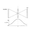
図4は、コントラスト検出法でオートフォーカス制御を行う場合の説明図である。
コントラスト検出法によれば、実際にレンズを駆動し、コントラストが最も高い位置を合焦点としている。すなわち、図4のレンズ位置Pが合焦点位置となるので、この位置Pで、レンズを固定しオートフォーカスロック状態とする。
続いてCPU11は、シャッタスイッチが全押しされたか否かを判別する(ステップS14)。
ステップS14の判別において、未だシャッタスイッチが全押しされていない場合には(ステップS14;No)、待機状態となる。
ステップS14の判別において、シャッタスイッチが全押しされた場合には(ステップS14;Yes)、CPU11は、角速度検出部30からの出力信号に基づいて所定のサンプリング期間における積分角速度を検出する(ステップS15)。
Here, the autofocus control will be described in detail.
FIG. 4 is an explanatory diagram when autofocus control is performed by the contrast detection method.
According to the contrast detection method, the lens is actually driven and the position with the highest contrast is set as the focal point. That is, since the lens position P in FIG. 4 is the in-focus position, the lens is fixed at this position P and the autofocus lock state is set.
Subsequently, the
If it is determined in step S14 that the shutter switch has not yet been fully pressed (step S14; No), a standby state is entered.
If it is determined in step S14 that the shutter switch is fully pressed (step S14; Yes), the
制御部10における積分角速度の算出について簡単に説明すると、制御部10は上記角速度検出信号に基づいて角速度(rad/秒)を算出し、この角速度(rad/秒)を所定のサンプリング間隔(秒)で積分することで積分角速度Σ(rad/秒)を算出する。実際には、制御部10は、積分角速度として、X軸方向積分角速度ΣxおよびY軸方向積分角速度Σyを算出する。
続いてCPU11は、X軸方向積分角速度ΣxおよびY軸方向積分角速度Σyに基づいてディジタルスチルカメラのパニング動作がなされたか否かを判別する(ステップS16)。ここで、パニング動作とは、例えば、画面中央に人物を配置した状態でシャッタスイッチを半押しして、人物に対するオートフォーカスロック状態とし、つづいてディジタルスチルカメラの向きを変えて、画面の側部に人物が配置されるように構図を直す動作をいう。
The calculation of the integral angular velocity in the
Subsequently, the
ステップS16の判別において、ディジタルスチルカメラにおいてパニング動作がなされた場合には(ステップS16;Yes)、手ぶれを考慮することなくオートフォーカスロック状態を維持する必要があるので、直ちに撮影処理に移行する(ステップS19)。すなわち、ステップS13のオートフォーカス処理によりオートフォーカスロック状態とされた合焦点位置にレンズを固定して、撮影カメラ22により撮像を行い、得られた画像データを撮影部RAM23に一時的に取り込むとともに、制御部10の制御下でリムーバブルメディア50に記録することとなる。
画像データのリムーバブルメディア50への記録動作と並行して表示パネル24には、撮像した画像が表示されることとなる。
If it is determined in step S16 that the panning operation is performed in the digital still camera (step S16; Yes), it is necessary to maintain the autofocus lock state without taking camera shake into consideration, and the process immediately proceeds to the photographing process ( Step S19). That is, the lens is fixed at the in-focus position that has been brought into the autofocus locked state by the autofocus process in step S13, the image is taken by the photographing
In parallel with the recording operation of the image data to the
ステップS16の判別において、ディジタルスチルカメラがパニング動作をしていない場合には(ステップS16;No)、制御部10のCPU11は、算出したX軸方向積分角速度ΣxおよびY軸方向積分角速度Σyに基づいてX軸方向手ぶれ量θx(mm)およびY軸方向手ぶれ量θy(mm)を算出し、X軸方向手ぶれ量θxおよびY軸方向手ぶれ量θyの少なくともいずれか一方が許容値を越えているか否かを判別する(ステップS17)。この場合において、この許容値は、ズーム倍率、シャッタ速度などの撮影条件によって適宜設定されている。
ステップS17の判別において、X軸方向手ぶれ量θxおよびY軸方向手ぶれ量θyの少なくともいずれか一方が許容値を越えている場合には(ステップS17;Yes)、オートフォーカス補正処理に移行する(ステップS18)。
If it is determined in step S16 that the digital still camera is not panning (step S16; No), the
If it is determined in step S17 that at least one of the X-axis direction camera shake amount θx and the Y-axis direction camera shake amount θy exceeds an allowable value (step S17; Yes), the process proceeds to an autofocus correction process (step S17). S18).
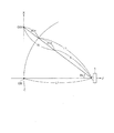
図5は、オートフォーカス補正処理の原理説明図である。
図5に示すように、手ぶれがない場合の合焦点位置Pおよび手ぶれが生じた場合の合焦点位置P1との差DFと、ディジタルスチルカメラ11のCCDの手ぶれに起因する移動量DXと、の間には、相関関係がある。従って、ディジタルスチルカメラ11の手ぶれに起因する移動量DXが検出できれば、合焦点位置を位置Pから位置P1に補正することができるはずである。
FIG. 5 is a diagram for explaining the principle of autofocus correction processing.
As shown in FIG. 5, the difference DF between the in-focus position P when there is no camera shake and the in-focus position P1 when camera shake occurs, and the movement amount DX caused by the camera shake of the CCD of the digital
図6は、X軸方向におけるオートフォーカス補正処理の説明図である。
図7は、Y軸方向におけるオートフォーカス補正処理の説明図である。
オートフォーカス補正処理において、CPU11は、算出したX軸方向手ぶれ量θxおよびY軸方向手ぶれ量θyに基づいてオートフォーカス補正量ΔLを算出する。
具体的には、まず、図6に示すように、Y軸方向手ぶれ量θyに基づいてY軸方向のオートフォーカス補正量ΔLyを次式により算出する。
ΔLy=L−L/cosθy
この結果、Y軸方向についてのみ手ぶれ量を補正した見かけ上の被写体OB1までの距離L1は次式の通りとなる。
L1=L+ΔLy
FIG. 6 is an explanatory diagram of the autofocus correction process in the X-axis direction.
FIG. 7 is an explanatory diagram of autofocus correction processing in the Y-axis direction.
In the autofocus correction process, the
Specifically, first, as shown in FIG. 6, the autofocus correction amount ΔLy in the Y-axis direction is calculated by the following equation based on the Y-axis direction camera shake amount θy.
ΔLy = L−L / cos θy
As a result, the apparent distance L1 to the subject OB1 in which the camera shake amount is corrected only in the Y-axis direction is expressed by the following equation.
L1 = L + ΔLy
続いてCPU11は、図7に示すように、X軸方向手ぶれ量θxおよび見かけ上の被写体OB1までの距離L1に基づいてX軸方向のオートフォーカス補正量ΔLxを次式により算出する。
ΔLx=L1−L1/cosθx
これらの結果に基づいて、CPU11は、オートフォーカス補正量ΔLを算出する。
ΔL=ΔLx+ΔLy
そして、CPU11は、カメラコントロール回路21を制御し、オートフォーカス補正量ΔLに基づいて、オートフォーカス補正処理を行わせ、ステップS13で求めた合焦点位置からオートフォーカス補正量ΔLだけずらした位置を新たな合焦点位置とする。そして、補正後の新たな合焦点位置に基づいて画像データを撮影部RAM23に一時的に取り込むとともに、制御部10の制御下でリムーバブルメディア50に記録することとなる。
Subsequently, as shown in FIG. 7, the
ΔLx = L1-L1 / cos θx
Based on these results, the
ΔL = ΔLx + ΔLy
Then, the
以上の説明のように、本実施形態によれば、シャッタスイッチの半押し状態においてオートフォーカス制御により得られた合焦点位置を手ぶれ量に相当する差分だけ補正する構成を採っているので、オートフォーカス補正処理に要する時間を短縮することができ、よりピントの合った画像を得ることが可能となる。 As described above, according to the present embodiment, since the in-focus position obtained by the autofocus control is corrected by a difference corresponding to the amount of camera shake when the shutter switch is half-pressed, the autofocus is performed. The time required for the correction process can be shortened, and a more focused image can be obtained.
以上の説明では、合焦点位置の検出にコントラスト検出法を用いた場合について説明したが、 オートフォーカス位置の検出方法としては、様々な方法用いることが可能である。すなわち、レーダーと同様の原理で、対象物(被写体)に赤外線・超音波などを照射し、その反射波が戻るまでの時間や照射角度により距離を検出するアクティブ検出法や、位相差検出法などのパッシブ検出法も適用が可能である。 In the above description, the case where the contrast detection method is used for detecting the in-focus position has been described. However, various methods can be used as the autofocus position detection method. In other words, an active detection method that detects the distance based on the time until the reflected wave returns and the irradiation angle based on the same principle as a radar, and a phase difference detection method. This passive detection method can also be applied.
以上の説明ではディジタルスチルカメラについて説明したが、携帯電話に設けられたカメ
ラや、PDA一体型カメラや、一眼レフカメラなど他の静止画を撮像可能な電子光学機器に適用が可能である。
以上の説明では、角速度に基づいてぶれ量を検出する構成を例示したが、これに限らず、加速度センサを用いてぶれ量を検出する構成としても良い。
In the above description, the digital still camera has been described. However, the present invention can be applied to other optical images such as a camera provided in a mobile phone, a PDA integrated camera, and a single-lens reflex camera.
In the above description, the configuration in which the shake amount is detected based on the angular velocity is illustrated, but the configuration is not limited thereto, and a configuration in which the shake amount is detected using an acceleration sensor may be used.
1…ディジタルスチルカメラ、10…制御部(手ぶれ量検出部、オートフォーカス補正部)、11…CPU(手ぶれ量検出部、オートフォーカス補正部)、20…撮影部、21…カメラコントロール回路(オートフォーカス機構部)、22…撮影カメラ(オートフォーカス機構部)、24…表示パネル、30…角速度検出部(手ぶれ量検出部)、50…リムーバルメディア、60…記録媒体、70…フレーム。
DESCRIPTION OF
Claims (4)
シャッタを操作するためのシャッタスイッチと、
ジャイロセンサが出力した角速度検出信号に基づいて、前記レンズの光軸方向を含む手ぶれ量を検出する手ぶれ量検出部と、
前記レンズの光軸方向の手ぶれ量に基づいて前記合焦点位置を補正し、当該補正後の合焦点位置に前記レンズを駆動させるべく補正制御を行うオートフォーカス補正部と、
前記シャッタスイッチの全押し操作がなされた場合に、前記ジャイロセンサが出力した角速度検出信号に基づいて算出される角速度を所定のサンプリング期間に亘り所定のサンプリング間隔で積分して積分角速度を算出し、当該積分角速度に基づいてパニング動作がなされたか否かを判定し、パニング動作がなれていないと判定した場合には前記積分角速度に基づいて手ぶれ量を算出する制御部と、を備え、
前記オートフォーカス機構部は、前記シャッタスイッチの半押し操作がなされたタイミングで前記レンズを合焦点位置に駆動して当該合焦点位置で保持し、
前記オートフォーカス補正部は、前記シャッタスイッチの全押し操作がなされたタイミングで前記制御部によって前記パニング動作がなされていないと判定された場合、当該制御部が算出した手ぶれ量が許容値を超えているときに、当該手ぶれ量に基づいて前記補正制御を行うことを特徴とする撮像装置。 An auto-focus mechanism that automatically focuses on the subject and drives the lens to the in-focus position;
A shutter switch for operating the shutter;
Based on the angular velocity detection signal output by the gyro sensor, a camera shake amount detection unit that detects a camera shake amount including the optical axis direction of the lens;
An autofocus correction unit that corrects the in-focus position based on the amount of camera shake in the optical axis direction of the lens, and performs correction control to drive the lens to the in-focus position after the correction;
When the shutter switch is fully pressed, the angular velocity calculated based on the angular velocity detection signal output from the gyro sensor is integrated at a predetermined sampling interval over a predetermined sampling period to calculate an integrated angular velocity, It is determined whether or not a panning operation has been performed based on the integral angular velocity, and when it is determined that the panning operation has not been performed, a control unit that calculates a camera shake amount based on the integral angular velocity, and
The autofocus mechanism unit drives the lens to the in-focus position at the timing when the shutter switch is half-pressed and holds the lens at the in-focus position;
When it is determined that the panning operation is not performed by the control unit at the timing when the shutter switch is fully pressed, the autofocus correction unit exceeds a permissible value. An image pickup apparatus that performs the correction control based on the amount of camera shake when the camera is in motion .
前記オートフォーカス機構部は、前記補正制御により、前記手ぶれ量に相当するだけ前記レンズの撮像素子に対する相対的な位置をずらすことを特徴とする撮像装置。 The imaging device according to claim 1 ,
The image pickup apparatus, wherein the autofocus mechanism unit shifts a relative position of the lens with respect to an image pickup element by an amount corresponding to the amount of camera shake by the correction control.
前記レンズを合焦点位置に駆動し、保持するオートフォーカス過程と、
ジャイロセンサが出力した角速度検出信号に基づいて、少なくとも前記レンズの光軸方向を含む手ぶれ量を検出する手ぶれ量検出過程と、
前記レンズの光軸方向の手ぶれ量に基づいて前記合焦点位置を補正し、当該補正後の合焦点位置を新たな合焦点位置として前記オートフォーカス機構に前記レンズを駆動させるべく補正制御を行うオートフォーカス補正過程と、
前記シャッタスイッチの全押し操作がなされた場合に、前記ジャイロセンサが出力した角速度検出信号に基づいて算出される角速度を所定のサンプリング期間に亘り所定のサンプリング間隔で積分して積分角速度を算出し、当該積分角速度に基づいてパニング動作がなされたか否かを判定し、パニング動作がなれていないと判定した場合には前記積分角速度に基づいて手ぶれ量を算出する過程と、を備え、
前記オートフォーカス過程は、前記シャッタスイッチの半押し操作がなされたタイミングで前記レンズを合焦点位置に駆動して当該合焦点位置で保持し、
前記オートフォーカス補正過程は、前記シャッタスイッチの全押し操作がなされたときに前記積分角速度に基づき前記パニング動作がなされていないと判定されることで前記積分角速度に基づき算出された手ぶれ量が許容値を超えている場合には、当該手ぶれ量に基づいて前記補正制御を行う、
ことを特徴とする撮像装置の制御方法。 In a control method of an imaging apparatus comprising: a shutter switch for operating a shutter; and an autofocus mechanism that automatically focuses on a subject and drives a lens to a focal position;
An autofocus process for driving and holding the lens at the in-focus position;
Based on the angular velocity detection signal output from the gyro sensor, a camera shake amount detection process for detecting a camera shake amount including at least the optical axis direction of the lens;
The auto focus position is corrected based on the amount of camera shake in the optical axis direction of the lens, and correction control is performed so that the auto focus mechanism drives the lens with the corrected focus position as a new focus position. Focus correction process,
When the shutter switch is fully pressed, the angular velocity calculated based on the angular velocity detection signal output from the gyro sensor is integrated at a predetermined sampling interval over a predetermined sampling period to calculate an integrated angular velocity, based on the integration velocity it is determined whether panning operation has been performed, when it is determined that the panning operation is not accustomed comprises the steps of calculating a shake amount on the basis of the integral angular velocity,
In the autofocus process, the lens is driven to the in-focus position at the timing when the shutter switch is half-pressed and held at the in-focus position,
In the autofocus correction process, it is determined that the panning operation is not performed based on the integral angular velocity when the shutter switch is fully pressed, and thus the amount of camera shake calculated based on the integral angular velocity is an allowable value. If it exceeds, the correction control is performed based on the amount of camera shake ,
And a method of controlling the imaging apparatus.
前記レンズを合焦点位置に駆動し、保持させ、
ジャイロセンサが出力した角速度検出信号に基づいて、少なくとも前記レンズの光軸方向を含む手ぶれ量を検出させ、
前記レンズの光軸方向の手ぶれ量に基づいて前記合焦点位置を補正させ、当該補正後の合焦点位置を新たな合焦点位置として前記オートフォーカス機構に前記レンズを駆動させ、
前記シャッタスイッチの全押し操作がなされた場合に、前記ジャイロセンサが出力した角速度検出信号に基づいて算出される角速度を所定のサンプリング期間に亘り所定のサンプリング間隔で積分して積分角速度を算出し、当該積分角速度に基づいてパニング動作がなされたか否かを判定し、パニング動作がなれていないと判定した場合には前記積分角速度に基づいて手ぶれ量を算出させ、
前記シャッタスイッチの半押し操作がなされたタイミングで前記レンズを合焦点位置に駆動して当該合焦点位置で保持させ、
前記シャッタスイッチの全押し操作がなされたときに前記積分角速度に基づき前記パニング動作がなされていないと判定されることで前記積分角速度に基づき算出された手ぶれ量が許容値を超えている場合には、前記レンズを前記手ぶれ量に基づく新たな合焦点位置に駆動させ、保持させる、
ことを特徴とする制御プログラム。 In a control program for controlling an image pickup apparatus having a shutter switch for operating a shutter and an autofocus mechanism for automatically focusing on a subject and driving a lens to a focal point position by a computer,
Drive and hold the lens at the in-focus position,
Based on the angular velocity detection signal output by the gyro sensor, the amount of camera shake including at least the optical axis direction of the lens is detected,
The in-focus position is corrected based on the amount of camera shake in the optical axis direction of the lens, the lens is driven by the autofocus mechanism with the corrected in-focus position as a new in-focus position,
When the shutter switch is fully pressed, the angular velocity calculated based on the angular velocity detection signal output from the gyro sensor is integrated at a predetermined sampling interval over a predetermined sampling period to calculate an integrated angular velocity, It is determined whether a panning operation has been performed based on the integral angular velocity, and when it is determined that the panning operation has not been performed, the amount of camera shake is calculated based on the integral angular velocity ,
The lens is driven to the in-focus position at the timing when the shutter switch is half-pressed and held at the in-focus position,
When it is determined that the panning operation is not performed based on the integral angular velocity when the shutter switch is fully pressed, and the amount of camera shake calculated based on the integral angular velocity exceeds an allowable value , Driving the lens to a new in-focus position based on the amount of camera shake and holding the lens;
A control program characterized by that.
Priority Applications (2)
| Application Number | Priority Date | Filing Date | Title |
|---|---|---|---|
| JP2005339715A JP4876550B2 (en) | 2005-11-25 | 2005-11-25 | Imaging apparatus, control method, and control program |
| US11/563,242 US7693405B2 (en) | 2005-11-25 | 2006-11-27 | Image pickup device, method of controlling image pickup device, and recording medium |
Applications Claiming Priority (1)
| Application Number | Priority Date | Filing Date | Title |
|---|---|---|---|
| JP2005339715A JP4876550B2 (en) | 2005-11-25 | 2005-11-25 | Imaging apparatus, control method, and control program |
Publications (3)
| Publication Number | Publication Date |
|---|---|
| JP2007147803A JP2007147803A (en) | 2007-06-14 |
| JP2007147803A5 JP2007147803A5 (en) | 2008-12-18 |
| JP4876550B2 true JP4876550B2 (en) | 2012-02-15 |
Family
ID=38209305
Family Applications (1)
| Application Number | Title | Priority Date | Filing Date |
|---|---|---|---|
| JP2005339715A Expired - Fee Related JP4876550B2 (en) | 2005-11-25 | 2005-11-25 | Imaging apparatus, control method, and control program |
Country Status (1)
| Country | Link |
|---|---|
| JP (1) | JP4876550B2 (en) |
Families Citing this family (5)
| Publication number | Priority date | Publication date | Assignee | Title |
|---|---|---|---|---|
| JP4552974B2 (en) | 2007-06-22 | 2010-09-29 | カシオ計算機株式会社 | Camera device, focus control method and program |
| JP5262928B2 (en) * | 2009-02-13 | 2013-08-14 | 富士通株式会社 | Imaging device, portable terminal device, and focusing mechanism control method |
| KR101909130B1 (en) * | 2012-02-13 | 2018-12-18 | 삼성전자주식회사 | Digital photographing apparatus and method for controlling thereof |
| JP6554658B2 (en) * | 2014-08-04 | 2019-08-07 | パナソニックIpマネジメント株式会社 | Imaging device and camera body |
| JP7208822B2 (en) * | 2019-02-22 | 2023-01-19 | キヤノン株式会社 | IMAGING DEVICE AND CONTROL METHOD THEREOF, PROGRAM, STORAGE MEDIUM |
Family Cites Families (7)
| Publication number | Priority date | Publication date | Assignee | Title |
|---|---|---|---|---|
| JP3302104B2 (en) * | 1993-06-30 | 2002-07-15 | キヤノン株式会社 | Imaging device |
| JPH0875987A (en) * | 1994-09-06 | 1996-03-22 | Asahi Optical Co Ltd | Range-finding device and automatic focusing device of camera |
| JP3728608B2 (en) * | 1995-04-28 | 2005-12-21 | 株式会社ニコン | Blur correction optical device |
| JP3735972B2 (en) * | 1996-11-06 | 2006-01-18 | 株式会社ニコン | Predictive distance measuring device and photographing device |
| JP4013283B2 (en) * | 1997-05-12 | 2007-11-28 | 株式会社ニコン | Camera with autofocus function |
| JP2001228499A (en) * | 2000-02-14 | 2001-08-24 | Sony Corp | Image pickup device and image pickup method |
| US7409149B2 (en) * | 2005-11-03 | 2008-08-05 | International Business Machines Corporation | Methods for improved autofocus in digital imaging systems |
-
2005
- 2005-11-25 JP JP2005339715A patent/JP4876550B2/en not_active Expired - Fee Related
Also Published As
| Publication number | Publication date |
|---|---|
| JP2007147803A (en) | 2007-06-14 |
Similar Documents
| Publication | Publication Date | Title |
|---|---|---|
| JP4522207B2 (en) | Camera system, camera body and interchangeable lens | |
| US7693406B2 (en) | Image capturing apparatus, method of controlling the same, and storage medium | |
| JP3697129B2 (en) | Imaging device | |
| JP4667052B2 (en) | Imaging device, camera body and interchangeable lens thereof | |
| US7693405B2 (en) | Image pickup device, method of controlling image pickup device, and recording medium | |
| JP4671705B2 (en) | Imaging device | |
| US7907205B2 (en) | Optical apparatus with unit for correcting blur of captured image caused by displacement of optical apparatus in optical-axis direction | |
| KR101663225B1 (en) | Method and Apparatus for processing digital image | |
| CN109417593B (en) | Imaging device, operation method, image processing device, and image processing method | |
| JP2005215388A (en) | Interchangeable lens and camera system using the same | |
| JP2016170285A (en) | Image blur correction device, optical equipment, imaging apparatus, and control method | |
| JP2011013645A (en) | Imaging device | |
| JP2011013645A5 (en) | ||
| JP4876550B2 (en) | Imaging apparatus, control method, and control program | |
| JP5011235B2 (en) | Imaging apparatus and imaging method | |
| JP2010271379A (en) | Imaging device | |
| JP4670647B2 (en) | Imaging apparatus, control method, and control program | |
| JP2013104921A (en) | Image pickup apparatus, image pickup system, and control method of image pickup apparatus | |
| JP2007147804A (en) | Moving picture taking device, control method and control program | |
| JP6168827B2 (en) | Image stabilization apparatus and optical apparatus | |
| JP4905048B2 (en) | IMAGING DEVICE, IMAGING DEVICE CONTROL METHOD, AND CONTROL PROGRAM | |
| JP2005173507A (en) | Amplification factor initial setting method of blurring detection signal, imaging device | |
| JP2007248672A (en) | Photographic device, control method and control program | |
| JP7451152B2 (en) | Imaging device, control method and computer program | |
| JP2007180990A (en) | Imaging apparatus, control method, and control program |
Legal Events
| Date | Code | Title | Description |
|---|---|---|---|
| A521 | Request for written amendment filed |
Free format text: JAPANESE INTERMEDIATE CODE: A523 Effective date: 20081029 |
|
| A621 | Written request for application examination |
Free format text: JAPANESE INTERMEDIATE CODE: A621 Effective date: 20081029 |
|
| A977 | Report on retrieval |
Free format text: JAPANESE INTERMEDIATE CODE: A971007 Effective date: 20101216 |
|
| A131 | Notification of reasons for refusal |
Free format text: JAPANESE INTERMEDIATE CODE: A131 Effective date: 20101221 |
|
| A521 | Request for written amendment filed |
Free format text: JAPANESE INTERMEDIATE CODE: A523 Effective date: 20110217 |
|
| RD02 | Notification of acceptance of power of attorney |
Free format text: JAPANESE INTERMEDIATE CODE: A7422 Effective date: 20110217 |
|
| A131 | Notification of reasons for refusal |
Free format text: JAPANESE INTERMEDIATE CODE: A131 Effective date: 20110510 |
|
| A521 | Request for written amendment filed |
Free format text: JAPANESE INTERMEDIATE CODE: A523 Effective date: 20110708 |
|
| TRDD | Decision of grant or rejection written | ||
| A01 | Written decision to grant a patent or to grant a registration (utility model) |
Free format text: JAPANESE INTERMEDIATE CODE: A01 Effective date: 20111101 |
|
| A01 | Written decision to grant a patent or to grant a registration (utility model) |
Free format text: JAPANESE INTERMEDIATE CODE: A01 |
|
| A61 | First payment of annual fees (during grant procedure) |
Free format text: JAPANESE INTERMEDIATE CODE: A61 Effective date: 20111114 |
|
| R150 | Certificate of patent or registration of utility model |
Ref document number: 4876550 Country of ref document: JP Free format text: JAPANESE INTERMEDIATE CODE: R150 |
|
| FPAY | Renewal fee payment (event date is renewal date of database) |
Free format text: PAYMENT UNTIL: 20141209 Year of fee payment: 3 |
|
| S531 | Written request for registration of change of domicile |
Free format text: JAPANESE INTERMEDIATE CODE: R313531 |
|
| R350 | Written notification of registration of transfer |
Free format text: JAPANESE INTERMEDIATE CODE: R350 |
|
| R250 | Receipt of annual fees |
Free format text: JAPANESE INTERMEDIATE CODE: R250 |
|
| R250 | Receipt of annual fees |
Free format text: JAPANESE INTERMEDIATE CODE: R250 |
|
| R250 | Receipt of annual fees |
Free format text: JAPANESE INTERMEDIATE CODE: R250 |
|
| LAPS | Cancellation because of no payment of annual fees |