JP4875467B2 - Sterilization structure of heat exchanger - Google Patents
Sterilization structure of heat exchanger Download PDFInfo
- Publication number
- JP4875467B2 JP4875467B2 JP2006313302A JP2006313302A JP4875467B2 JP 4875467 B2 JP4875467 B2 JP 4875467B2 JP 2006313302 A JP2006313302 A JP 2006313302A JP 2006313302 A JP2006313302 A JP 2006313302A JP 4875467 B2 JP4875467 B2 JP 4875467B2
- Authority
- JP
- Japan
- Prior art keywords
- heat exchange
- water
- silver
- water receiving
- silver electrode
- Prior art date
- Legal status (The legal status is an assumption and is not a legal conclusion. Google has not performed a legal analysis and makes no representation as to the accuracy of the status listed.)
- Expired - Fee Related
Links
- 230000001954 sterilising effect Effects 0.000 title claims description 30
- 238000004659 sterilization and disinfection Methods 0.000 title claims description 29
- 229910052709 silver Inorganic materials 0.000 claims description 100
- 239000004332 silver Substances 0.000 claims description 100
- XLYOFNOQVPJJNP-UHFFFAOYSA-N water Substances O XLYOFNOQVPJJNP-UHFFFAOYSA-N 0.000 claims description 84
- BQCADISMDOOEFD-UHFFFAOYSA-N Silver Chemical compound [Ag] BQCADISMDOOEFD-UHFFFAOYSA-N 0.000 claims description 63
- -1 silver ions Chemical class 0.000 claims description 38
- RYGMFSIKBFXOCR-UHFFFAOYSA-N Copper Chemical compound [Cu] RYGMFSIKBFXOCR-UHFFFAOYSA-N 0.000 claims description 29
- 229910052802 copper Inorganic materials 0.000 claims description 29
- 239000010949 copper Substances 0.000 claims description 29
- 239000012530 fluid Substances 0.000 claims description 7
- 239000003507 refrigerant Substances 0.000 claims description 6
- 229910052751 metal Inorganic materials 0.000 claims description 5
- 239000002184 metal Substances 0.000 claims description 5
- 238000001816 cooling Methods 0.000 description 14
- FOIXSVOLVBLSDH-UHFFFAOYSA-N Silver ion Chemical compound [Ag+] FOIXSVOLVBLSDH-UHFFFAOYSA-N 0.000 description 9
- 239000000498 cooling water Substances 0.000 description 9
- 241000894006 Bacteria Species 0.000 description 8
- 230000001580 bacterial effect Effects 0.000 description 5
- 238000009792 diffusion process Methods 0.000 description 4
- 229910052782 aluminium Inorganic materials 0.000 description 3
- XAGFODPZIPBFFR-UHFFFAOYSA-N aluminium Chemical compound [Al] XAGFODPZIPBFFR-UHFFFAOYSA-N 0.000 description 3
- KYKAJFCTULSVSH-UHFFFAOYSA-N chloro(fluoro)methane Chemical compound F[C]Cl KYKAJFCTULSVSH-UHFFFAOYSA-N 0.000 description 2
- 238000010586 diagram Methods 0.000 description 2
- 238000001962 electrophoresis Methods 0.000 description 2
- 239000005416 organic matter Substances 0.000 description 2
- 239000000126 substance Substances 0.000 description 2
- 241000195493 Cryptophyta Species 0.000 description 1
- RWSOTUBLDIXVET-UHFFFAOYSA-N Dihydrogen sulfide Chemical compound S RWSOTUBLDIXVET-UHFFFAOYSA-N 0.000 description 1
- 230000000844 anti-bacterial effect Effects 0.000 description 1
- 230000000903 blocking effect Effects 0.000 description 1
- 238000009395 breeding Methods 0.000 description 1
- 230000001488 breeding effect Effects 0.000 description 1
- 239000002826 coolant Substances 0.000 description 1
- 238000005260 corrosion Methods 0.000 description 1
- 230000007797 corrosion Effects 0.000 description 1
- 125000004122 cyclic group Chemical group 0.000 description 1
- 230000000694 effects Effects 0.000 description 1
- 238000010828 elution Methods 0.000 description 1
- 229910000037 hydrogen sulfide Inorganic materials 0.000 description 1
- 150000002500 ions Chemical class 0.000 description 1
- 238000004519 manufacturing process Methods 0.000 description 1
- 238000000034 method Methods 0.000 description 1
- 239000002244 precipitate Substances 0.000 description 1
- 230000001737 promoting effect Effects 0.000 description 1
- 238000000746 purification Methods 0.000 description 1
- VFWRGKJLLYDFBY-UHFFFAOYSA-N silver;hydrate Chemical compound O.[Ag].[Ag] VFWRGKJLLYDFBY-UHFFFAOYSA-N 0.000 description 1
- 239000011345 viscous material Substances 0.000 description 1
Images


Landscapes
- Devices For Blowing Cold Air, Devices For Blowing Warm Air, And Means For Preventing Water Condensation In Air Conditioning Units (AREA)
- Air Filters, Heat-Exchange Apparatuses, And Housings Of Air-Conditioning Units (AREA)
- Water Treatment By Electricity Or Magnetism (AREA)
Description
本発明は、装置の下部に水を溜める水受け部と、装置に導入される流体を対象として熱交換を促進する熱交換構造体とを備える熱交換装置の殺菌構造に関する。 The present invention relates to a sterilization structure for a heat exchange device, which includes a water receiving portion that stores water in a lower portion of the device, and a heat exchange structure that promotes heat exchange for a fluid introduced into the device.
一般に、銀イオンには殺菌効果があることが知られている。このため、従来、銀イオンによる殺菌手段は様々な装置に適用されている。 In general, silver ions are known to have a bactericidal effect. For this reason, conventionally, the sterilization means using silver ions has been applied to various apparatuses.
このような銀イオンによる殺菌手段を適用するものとしては、例えば、アノード及びカソードを銀電極で構成し、両極間に電圧を印加して銀イオンを発生させ、流水中に混入させる流水浄化装置(例えば、特許文献1参照)が知られている。この流水浄化装置は、風呂、温泉等の循環路に取り付けて、水中に銀イオンを発生させ、殺菌・殺藻して水質の浄化を図る。 As a method for applying such sterilization means using silver ions, for example, an anode and a cathode are composed of silver electrodes, a voltage is applied between the two electrodes to generate silver ions, and a flowing water purifying device that mixes in flowing water ( For example, see Patent Document 1). This flowing water purification device is attached to a circulation path such as a bath or a hot spring to generate silver ions in the water, and sterilize and kill the algae to purify the water quality.
一方、空気調和機の室内機や冷却塔といった、装置の下部に水を溜める水受け部と、装置に導入される流体を対象として熱交換を促進する熱交換構造体とを備える熱交換装置においては、熱交換構造体から流れ落ちる水に有機物が含まれることがあるため、この有機物を餌として水受け部において細菌が繁殖することが知られている。細菌は、繁殖する際に、スライム等の粘性物質を産生するため、この熱交換装置において、排水通路や排水ポンプを詰まらせて水受け部からの排水を妨げる等、様々な問題を引き起こしていた。 On the other hand, in a heat exchanging apparatus comprising a water receiving part for accumulating water at the lower part of the apparatus, such as an air conditioner indoor unit and a cooling tower, and a heat exchanging structure for promoting heat exchange for a fluid introduced into the apparatus In some cases, organic matter may be contained in the water flowing down from the heat exchange structure, and it is known that bacteria propagate in the water receiving portion using this organic matter as food. Bacteria produce slime and other viscous substances when breeding, and this heat exchanger caused various problems such as blocking drainage from the water receiving section by clogging drainage passages and drainage pumps. .
この種の問題に対しては、熱交換装置である空気調和機の室内機において、水受け部であるドレンパンに、銀電極をアノードとし、金属電極をカソードとして設け、両極間に電圧を印加して銀イオンを発生させ、ドレン水の細菌繁殖を抑制すること(例えば、特許文献2参照)が提案されている。 For this type of problem, in an indoor unit of an air conditioner that is a heat exchange device, a drain pan that is a water receiving part is provided with a silver electrode as an anode and a metal electrode as a cathode, and a voltage is applied between both electrodes. Therefore, it has been proposed to generate silver ions and suppress bacterial growth of drain water (see, for example, Patent Document 2).
前記従来の殺菌手段は、銀電極と銀電極または金属電極との二つの電極を設けて、銀電極をアノードとし、金属電極等をカソードとして、両極間に電圧を印加し、銀イオンを発生させるものである。このため、特許文献1に記載された流水浄化装置のように、銀イオンを流水中に混入させる場合には、発生した銀イオンは流水によって拡散されるため有効な殺菌手段となり得る。
The conventional sterilization means is provided with two electrodes, a silver electrode and a silver electrode or a metal electrode, and a silver electrode is used as an anode and a metal electrode or the like is used as a cathode to apply a voltage between both electrodes to generate silver ions. Is. For this reason, when the silver ions are mixed into the flowing water as in the flowing water purifying apparatus described in
しかし、特許文献2に記載された空気調和機の室内機のドレンパンに溜まったドレン水のように、滞留した水に銀イオンを発生させた場合には、電極間では電気泳動するものの、それ以外の領域では積極的な拡散手段はなく、濃度勾配による拡散となる。このため、電極からせいぜい±10cm程度の範囲までしか拡散せず、ドレンパン等の水受け部全体に銀イオンを行き渡らせることは困難であった。
However, when silver ions are generated in the accumulated water like the drain water accumulated in the drain pan of the indoor unit of the air conditioner described in
また、従来の殺菌手段では、それぞれの電極で下記化1に示す反応が進行している。銀イオンはカソードに向かって電気泳動するため、カソード付近では発生した水酸化物イオンと反応し、水に不溶な酸化銀(Ag2O)となって沈殿する場合や、電子を取込んだ銀イオンがカソードで銀として析出するという場合があり、このような問題が銀イオンの拡散をさらに妨げていた。
Moreover, in the conventional sterilization means, the reaction shown in the following
[化1]
アノード : Ag → Ag+ + e-
カソード : 1/4O2 + 1/2H2O +e- → OH- ( Ag+ + e- → Ag )
[Chemical 1]
Anode: Ag → Ag + + e -
Cathode: 1 / 4O 2 + 1 / 2H 2 O + e - → OH - (Ag + + e - → Ag)
したがって、従来の殺菌手段では、空気調和機や冷却塔等の熱交換装置に対する殺菌効果はほとんど期待できなかった。 Therefore, the conventional sterilization means could hardly be expected to have a sterilizing effect on a heat exchange device such as an air conditioner or a cooling tower.
一方、空気調和機の室内機等の熱交換装置において、ドレン水等の水受け部に溜まった水には、フロンや冷水等の冷媒が流れる銅配管のような熱交換構造体の一部が浸漬されている。このため、例えば、空気調和機の室内機において、銀イオンが銅配管付近にまで拡散した場合には、銅よりイオン化傾向の小さい銀イオンが銅配管の表面に析出し、その代わりに、銅が溶出して銅配管が腐食されるという問題があった。 On the other hand, in heat exchangers such as indoor units of air conditioners, a part of the heat exchange structure such as copper piping through which refrigerant such as chlorofluorocarbon or cold water flows is stored in the water receiving part such as drain water. Soaked. For this reason, for example, in an indoor unit of an air conditioner, when silver ions diffuse to the vicinity of a copper pipe, silver ions having a smaller ionization tendency than copper are deposited on the surface of the copper pipe. There was a problem that the copper piping was corroded and corroded.
また、アノードとカソードとの間には、その電極間を遠回りして流れる迷走電流が発生する場合があり、この迷走電流が銅配管等の熱交換構造体に干渉して腐食するという問題もあった。さらに、熱交換構造体は、水の中に細菌が発生している場合には、細菌が産生する硫化水素によっても腐食される虞があった。 In addition, stray currents flowing between the electrodes may occur between the anode and the cathode, and this stray current may corrode due to interference with a heat exchange structure such as a copper pipe. It was. Furthermore, when the bacteria are generated in the water, the heat exchange structure may be corroded by hydrogen sulfide produced by the bacteria.
本発明は上記の問題に鑑みて案出されたものであり、水受け部に銀イオンを拡散させて細菌の繁殖を抑制すると共に、熱交換構造体が腐食されるのを防止することができる熱交換装置の殺菌構造を提供することを目的とするものである。 The present invention has been devised in view of the above problems, and can suppress the propagation of bacteria by diffusing silver ions in the water receiving portion and prevent the heat exchange structure from being corroded. It aims at providing the sterilization structure of a heat exchange apparatus.
上記目的を達成するための本発明に係る熱交換装置の殺菌構造の第1特徴構成は、
装置の下部に水を溜める水受け部と、装置に導入される流体を対象として熱交換を促進する熱交換構造体とを備え、当該熱交換構造体が、銀よりイオン化傾向が大きい金属を主成分として構成してあると共に、前記水受け部に溜まった水に少なくとも一部が浸漬するように配置してある熱交換装置において、
前記水受け部の内部に配置した銀電極と、当該銀電極をアノードとし、前記熱交換構造体をカソードとして接続し、両極間に電圧を印加して前記水受け部に溜まった水の中に銀イオンを発生させる電圧供給手段とを備え、
前記銀電極は、前記水受け部に溜まる水に浸漬されるとともに、前記熱交換構造体のうち前記水受け部に溜まる水に浸漬する浸漬部分の長手方向に沿って前記熱交換構造体と所定の間隔を設けて配置され、前記電圧供給手段との接続部が前記長手方向において離間した位置に複数備えられた点にある。
In order to achieve the above object, the first characteristic configuration of the sterilization structure of the heat exchange device according to the present invention is:
A water receiving part for storing water in the lower part of the apparatus, and a heat exchange structure that promotes heat exchange for the fluid introduced into the apparatus, and the heat exchange structure is mainly made of a metal that has a higher ionization tendency than silver. In the heat exchange device that is configured as a component and arranged so that at least a portion is immersed in water accumulated in the water receiving portion,
The silver electrode disposed inside the water receiving part, the silver electrode as an anode, the heat exchange structure as a cathode, and a voltage applied between both electrodes to collect water in the water receiving part. Voltage supply means for generating silver ions,
The silver electrode is immersed in water accumulated in the water receiving portion, and is predetermined with the heat exchange structure along the longitudinal direction of the immersed portion of the heat exchange structure immersed in water accumulated in the water receiving portion. And a plurality of connecting portions with the voltage supply means are provided at positions separated in the longitudinal direction .
つまり、この構成によれば、アノードにおいて発生する銀イオンは、カソードである熱交換構造体に向かう電気泳動をドライビングフォースとして拡散するため、幅広い範囲に行き渡らせることができる。
また、熱交換構造体をカソードとしているため、熱交換構造体に対しては防食電流が流れることになる。このため、熱交換構造体の電位が下がることにより、内部の電位差が無くなり、熱交換構造体における腐食反応を抑制することができる。
さらには、熱交換構造体そのものをカソードとすることにより、熱交換構造体に対する迷走電流の干渉を無くすこともできる。
したがって、水受け部に銀イオンを拡散させて細菌の繁殖を抑制すると共に、熱交換構造体が腐食されるのを防止することができる。
That is, according to this configuration, the silver ions generated in the anode diffuse as electrophoresis force toward the heat exchange structure that is the cathode, and thus can be spread over a wide range.
In addition, since the heat exchange structure is used as a cathode, an anticorrosion current flows through the heat exchange structure. For this reason, when the electric potential of a heat exchange structure falls, an internal electric potential difference is lose | eliminated and the corrosion reaction in a heat exchange structure can be suppressed.
Furthermore, by using the heat exchange structure itself as a cathode, interference of stray currents to the heat exchange structure can be eliminated.
Therefore, silver ions can be diffused in the water receiving portion to suppress the growth of bacteria, and the heat exchange structure can be prevented from being corroded.
また、この構成によれば、銀電極の各部において銀イオンが発生させることができるため、水受け部の幅広い範囲に銀イオンを拡散させることができる。また、所定量の銀イオンを発生させる場合には、単位面積当りの銀イオンの発生量を少なくすることができるため、電流密度を低く設定することができる。このため、必要な印加電圧も小さくすることができる。 Moreover , according to this structure, since silver ion can be generated in each part of a silver electrode, silver ion can be diffused in the wide range of a water receiving part. In addition, when a predetermined amount of silver ions is generated, the amount of silver ions generated per unit area can be reduced, so that the current density can be set low. For this reason, a required applied voltage can also be made small.
そして、この構成によれば、銀イオンは、熱交換構造体の周囲に配置された銀電極から熱交換構造体に向かって発生するため、水受け部の全体に亘って銀イオンを拡散させることができる。 And according to this structure, since silver ion generate | occur | produces toward the heat exchange structure from the silver electrode arrange | positioned around the heat exchange structure, it diffuses silver ion over the whole water receiving part. Can do.
さらに、この構成によれば、銀電極に電圧供給手段との接続部を複数設けることにより、銀電極と電圧供給手段との接続を切れ難くして、銀電極と電圧供給手段との接続の一つが切れた場合でも、継続して銀イオンを発生させることができ、銀電極を有効に利用することができる。したがって、長期に亘って細菌の繁殖を抑制することができる。 Further , according to this configuration, by providing a plurality of connecting portions with the voltage supply means on the silver electrode, it is difficult to disconnect the silver electrode and the voltage supply means, and the connection between the silver electrode and the voltage supply means is reduced. Even when one breaks, silver ions can be continuously generated, and the silver electrode can be used effectively. Therefore, bacterial growth can be suppressed over a long period of time.
本発明に係る熱交換装置の殺菌構造の第2特徴構成は、前記銀電極を複数備える点にある。 The 2nd characteristic structure of the sterilization structure of the heat exchange apparatus which concerns on this invention exists in the point provided with two or more said silver electrodes.
つまり、この構成によれば、銀電極を複数設けることによって銀イオンの発生面積を大きくすることができるため、銀イオンをより拡散することができる。また、銀電極を複数設けることで、電圧供給手段との接続部も多くなる。このため、銀電極と電圧供給手段との接続が切れ難くなり、継続して銀イオンを発生させることができ、長期に亘って細菌の繁殖を抑制することができる。 That is, according to this configuration, the silver ion generation area can be increased by providing a plurality of silver electrodes, so that the silver ions can be further diffused. In addition, providing a plurality of silver electrodes increases the number of connecting portions with the voltage supply means. For this reason, it becomes difficult to disconnect the silver electrode from the voltage supply means, it is possible to continuously generate silver ions, and to suppress the growth of bacteria over a long period of time.
本発明に係る熱交換装置の殺菌構造の第3特徴構成は、前記銀電極は、平板状またはワイヤ状である点にある。 The 3rd characteristic structure of the sterilization structure of the heat exchange apparatus which concerns on this invention exists in the point whose said silver electrode is flat form or wire form.
つまり、この構成によれば、電極を任意の形状に変形して配置することができる。このため、水受け部の限られたスペースにおいても、銀イオンの発生面積が大きくなるように銀電極を配置することができる。 In other words, according to this configuration, the electrode can be deformed and arranged in an arbitrary shape. For this reason, a silver electrode can be arrange | positioned so that the generation | occurrence | production area of silver ion may become large also in the limited space of a water receiving part.
本発明に係る熱交換装置の殺菌構造の第4特徴構成は、前記熱交換構造体は、内部に冷媒が流れる銅配管である点にある。 The 4th characteristic structure of the sterilization structure of the heat exchange apparatus which concerns on this invention exists in the point in which the said heat exchange structure is a copper piping through which a refrigerant | coolant flows.
つまり、この構成によれば、水受け部に銀イオンを発生させて細菌の繁殖を抑制すると共に、銅配管を防食することができるため、銅配管が腐食されて冷媒が漏れ出すのを防止することができる。 In other words, according to this configuration, silver ions are generated in the water receiving portion to suppress bacterial growth, and the copper piping can be prevented from being corroded, so that the copper piping is corroded to prevent the refrigerant from leaking out. be able to.
〔第一の実施形態〕
以下に、本発明に係る熱交換装置の殺菌構造の第一の実施形態について図面を参照して説明する。ここでは、本発明に係る熱交換装置の殺菌構造を、熱交換装置の一例である天井埋込型の空気調和機の室内機1に適用した場合を例として説明する。
[First embodiment]
Below, 1st embodiment of the sterilization structure of the heat exchange apparatus which concerns on this invention is described with reference to drawings. Here, the case where the sterilization structure for a heat exchange device according to the present invention is applied to an
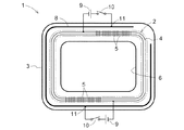
本実施形態に係る空気調和機の室内機1は、図1に模式的に示したように、室内機1に導入される流体としての空気を冷却または加温する熱交換構造体としての熱交換器2と、冷房時に熱交換器2から滴下するドレン水を室内機1の下部に溜める水受け部としてのドレンパン3とを備えて構成される。熱交換器2は、冷房運転時、内部にフロン等の冷媒が流れる銅配管4を備えており、この銅配管4には、銅配管4の長手方向と略垂直の方向に一定間隔で配列された複数のアルミニウム製のフィン5が設けてある。また、ドレンパン3には、溜まったドレン水が排水ポンプ7に集まるように底部に勾配(図示しない)が設けてある。なお、銅配管4は、実際には図2に示すように、環状体を形成し、この環状体がドレンパン3の底部から図1における上方に複数積層されている。
As schematically shown in FIG. 1, the
このような空気調和機の室内機1は、冷房運転時には、ファン(図示しない)を駆動することによって吸込口6より取込んだ室内の空気を、銅配管4に流れる冷媒によって冷却されたフィン5の隙間に通過させて熱交換し、冷風として吹出口(図示しない)より室内に送る。この際、銅配管4及びフィン5の表面には、空気に含有される水蒸気が温度低下により凝縮した水滴が付着する。この水滴がドレン水としてドレンパン3に溜められる。ドレンパン3に溜まったドレン水は、排水ポンプ7により所定の間隔で外部に排水される。なお、ドレン水は排水ポンプ7によって完全には排出できないため、空気調和機の冷房運転シーズンでは、ドレンパン3にはドレン水がある程度溜まっており、銅配管4及びフィン5のそれぞれの一部はドレン水に浸漬した状態となる。
The
本実施形態に係る空気調和機の室内機1の殺菌構造は、図1に示すように、ドレンパン3の内部に配置した銀電極8と、銀電極8をアノードとし、銀よりイオン化傾向が大きい銅配管4をカソードとして接続する電圧供給手段としての直流電源9とを備えている。直流電源9には銀電極8及び銅配管4への通電のオン・オフを切り換えるスイッチ10が設けてあり、このスイッチ10をオンにして銀電極8と銅配管4との間に電圧を印加し、ドレン水の中に銀イオンを発生させる。これにより、ドレン水における細菌の繁殖を抑制することができる。また、この際、銅配管4には防食電流が流れるため、銅配管4が腐食されるのを防止することもできる。
As shown in FIG. 1, the sterilization structure of the
銀電極8は、本実施形態においてはワイヤ状であり、ドレン水に浸漬した環状の銅配管4の長手方向に沿って、所定の間隔で、その周囲を略取り囲むように配置してある。これにより、銀電極8の長手方向全体から銀イオンを発生させ、銅配管4に向かって電気泳動させることができるため、図3に斜線領域で示すように、ドレンパン3の幅広い領域に銀イオンを行き渡らせることができる。なお、銅配管4と銀電極8との間隔は、小さい方が必要な印加電圧は小さくなるが、大きい方がドレンパン3の全体により拡散し易くなる。また、銀電極8は、ワイヤ形状に限らず、平板状等、任意の形状のものが適用可能であるが、本実施形態のようにドレン水に浸漬する部分の面積を大きくすれば、所定量の銀イオンを発生させるのに必要な電極間の電圧をより低く設定することができるため好ましい。
The
銀電極8は、本実施形態では直流電源9とは二箇所の接続部11において接続してある。直流電源9との接続部11は、複数設けることが好ましい。すなわち、直流電源9との接続部11を複数設けることにより、銀電極8と直流電源9との接続の一つが切れたとしても、継続して銀イオンを発生させることができ、銀電極8を有効に利用することができる。このため、長期に亘って細菌の繁殖を抑制することができる。したがって、銀電極8の直流電源9との接続部11は多い方が好都合である。
In this embodiment, the
接続部11は、銀電極8のうち、ドレン水に浸漬し難い部分に設けることが好ましい。すなわち、銀イオンは、銀電極8のドレン水に浸漬した部分から溶出する。このため、銀電極8のうち、ドレン水に浸漬する頻度が少ない部分に接続部11を設けることにより、その部分の銀電極8の減少が抑えられ、銀電極8と直流電源9との接続が切れ難くなる。したがって、接続部11は、銀電極8のうち、ドレンパン3の最も水深が浅い位置(勾配の高い側)にある部分に設けることが好ましい。また、銀電極8が、平板状等、図1における上下方向に高さがある場合は、銀電極8のより高い位置に設けることが好ましい。
It is preferable to provide the
本実施形態においては、一つの銀電極8を環状の銅配管4の周囲を略取り囲むように配置した例を示したが、特に限定されない。図4に示すように、L字状の銀電極8aを二つ設けて銅配管4の周囲に配置することや、棒状または板状の銀電極を複数設けて銅配管4の長手方向に沿って配置することもできる。さらに、複数の銀電極を銅配管4の周囲に点在させて配置してもよい。
In this embodiment, although the example which has arrange | positioned one
また、本実施形態においては、銀電極8の二箇所の接続部11に対し、二つの直流電源9を設けた例を示したが、図5に示すように、二箇所の接続部11を、一つの直流電源9と並列に接続してもよい。もちろん、この場合であっても接続部11は2箇所に限定されない。
Moreover, in this embodiment, although the example which provided the two
このような空気調和機の室内機1の殺菌構造は、ドレン水の中における銀イオンの濃度が所定濃度以上を保つように制御する。例えば、所定の時間間隔でスイッチ10のオン・オフを切り換えるように設定することができ、また、スイッチ10を冷房運転スイッチ(図示しない)と連動させたり、ドレンパン3におけるドレン水の水位を検知してスイッチ10のオン・オフを切り換えるように設定したりしてもよい。
Such a sterilization structure of the
また、空気調和機の室内機1の殺菌構造の運転条件は、特に限定はされず、銀電極8の形状、必要な銀イオンの溶出量等によって、数V〜数十Vの電圧で、数分〜数時間行う等、任意に設定することができる。一般に、銀イオンの濃度が2mg/L以上の場合に殺菌に好ましい濃度であるとされており、例えば、1Lのドレン水の中の銀イオンを2mg/L以上にするためには、銀電極8が、直径2mm、長さ170cmのワイヤ状の場合、電流1〜10mA、電圧1〜4Vで、5〜20分程度行えばよい。一例として、電流5mA、電圧2.7Vで10分間運転した場合に、ドレンパン3の四隅の銀イオン濃度を測定したところ、3.5mg/L、3.5mg/L、4.3mg/L、4.5mg/Lと、いずれの部分も2mg/L以上であり、分散性を有することが確認できた。
In addition, the operating conditions of the sterilization structure of the
〔第二の実施形態〕
次に、本発明に係る熱交換装置の殺菌構造の第二の実施形態について説明する。ここでは、本発明に係る熱交換装置の殺菌構造を、図6に示すように、熱交換装置の別の一例である冷却塔21に適用した場合を例として説明する。
[Second Embodiment]
Next, 2nd embodiment of the sterilization structure of the heat exchange apparatus which concerns on this invention is described. Here, the case where the sterilization structure for a heat exchange device according to the present invention is applied to a
本実施形態に係る冷却塔21は、冷凍機で使用された後、冷却塔21に導入される流体としての冷却水を、冷却するために外気との熱交換を促進する熱交換構造体としてのフィン22と、フィン22から流れ落ちる冷却水を冷却塔21の下部に溜める水受け部としての水槽23とを備えて構成される。フィン22は、アルミニウム製のもので、一定間隔で平行に複数配列してあり、このフィン22に散水器24によって冷却水を滴下する。この冷却水は、フィン22の表面を流れ落ちる際にファン25によって導入された外気と熱交換し、冷却されて水槽23に溜まる。このため、フィン22の一部は、水槽23に溜まった冷却水に浸漬した状態となる。なお、水槽23に溜まった冷却水21は、ポンプ26により冷凍機に送られ、再び使用される。
The
このような冷却塔21の殺菌構造は、水槽23の内部に、フィン22の冷却水に浸漬した部分の長手方向に沿って配置した銀電極27と、銀電極27をアノードとし、銀よりイオン化傾向が大きいアルミニウム製のフィン22をカソードとして接続する電圧供給手段としての直流電源28とを備えている。直流電源28には銀電極27及びフィン22への通電のオン・オフを切り換えるスイッチ29が設けてあり、このスイッチ29をオンにして銀電極27とフィン22との間に電圧を印加し、水槽23の冷却水の中に銀イオンを発生させる。尚、殺菌構造のその他の構成は、第一の実施形態と同様である。
Such a sterilization structure of the
このような構成により、銀イオンを水槽23の全体の領域に拡散させることができるため、冷却水における細菌の繁殖を抑制することができる。また、この際、フィン22には防食電流が流れるため、フィン22に対する防食効果も生じる。
With such a configuration, silver ions can be diffused in the entire region of the
本発明に係る熱交換装置の殺菌構造は、空気調和機の室内機や冷却塔に限定されず、装置の下部に水を溜める水受け部と、装置に導入される流体を対象として熱交換を促進する熱交換構造体とを備えた、様々な熱交換装置に適用することができる。 The sterilization structure of the heat exchange device according to the present invention is not limited to an indoor unit or a cooling tower of an air conditioner, and performs heat exchange for a water receiving portion that stores water in a lower portion of the device and a fluid introduced into the device. It can be applied to various heat exchange devices with a heat exchange structure to promote.
1 室内機
2 熱交換器(熱交換構造体)
3 ドレンパン(水受け部)
8 銀電極
9 直流電源(電圧供給手段)
1
3 Drain pan (water receiving part)
8
Claims (4)
前記水受け部の内部に配置した銀電極と、当該銀電極をアノードとし、前記熱交換構造体をカソードとして接続し、両極間に電圧を印加して前記水受け部に溜まった水の中に銀イオンを発生させる電圧供給手段とを備え、
前記銀電極は、前記水受け部に溜まる水に浸漬されるとともに、前記熱交換構造体のうち前記水受け部に溜まる水に浸漬する浸漬部分の長手方向に沿って前記熱交換構造体と所定の間隔を設けて配置され、前記電圧供給手段との接続部が前記長手方向において離間した位置に複数備えられた熱交換装置の殺菌構造。 A water receiving part for storing water in the lower part of the apparatus, and a heat exchange structure that promotes heat exchange for the fluid introduced into the apparatus, and the heat exchange structure is mainly made of a metal that has a higher ionization tendency than silver. In the heat exchange device that is configured as a component and arranged so that at least a portion is immersed in water accumulated in the water receiving portion,
The silver electrode disposed inside the water receiving part, the silver electrode as an anode, the heat exchange structure as a cathode, and a voltage applied between both electrodes to collect water in the water receiving part. Voltage supply means for generating silver ions,
The silver electrode is immersed in water accumulated in the water receiving portion, and is predetermined with the heat exchange structure along the longitudinal direction of the immersed portion of the heat exchange structure immersed in water accumulated in the water receiving portion. The heat disinfection structure of the heat exchange device is provided with a plurality of connecting portions with the voltage supply means at positions spaced apart in the longitudinal direction.
Priority Applications (1)
| Application Number | Priority Date | Filing Date | Title |
|---|---|---|---|
| JP2006313302A JP4875467B2 (en) | 2006-11-20 | 2006-11-20 | Sterilization structure of heat exchanger |
Applications Claiming Priority (1)
| Application Number | Priority Date | Filing Date | Title |
|---|---|---|---|
| JP2006313302A JP4875467B2 (en) | 2006-11-20 | 2006-11-20 | Sterilization structure of heat exchanger |
Publications (2)
| Publication Number | Publication Date |
|---|---|
| JP2008128549A JP2008128549A (en) | 2008-06-05 |
| JP4875467B2 true JP4875467B2 (en) | 2012-02-15 |
Family
ID=39554559
Family Applications (1)
| Application Number | Title | Priority Date | Filing Date |
|---|---|---|---|
| JP2006313302A Expired - Fee Related JP4875467B2 (en) | 2006-11-20 | 2006-11-20 | Sterilization structure of heat exchanger |
Country Status (1)
| Country | Link |
|---|---|
| JP (1) | JP4875467B2 (en) |
Families Citing this family (1)
| Publication number | Priority date | Publication date | Assignee | Title |
|---|---|---|---|---|
| CN114962993A (en) * | 2022-01-19 | 2022-08-30 | 北京未来氢能科技有限公司 | Hydrogen storage fuel cell air conditioning system and hydrogenation equipment |
Family Cites Families (3)
| Publication number | Priority date | Publication date | Assignee | Title |
|---|---|---|---|---|
| JP3261975B2 (en) * | 1996-05-22 | 2002-03-04 | 日立電線株式会社 | Car cooler with sterilizing filter |
| JP3052941B2 (en) * | 1998-08-28 | 2000-06-19 | ダイキン工業株式会社 | Air conditioning indoor unit |
| JP2001033058A (en) * | 1999-07-19 | 2001-02-09 | Matsushita Electric Ind Co Ltd | Electrical equipment with heat exchanger |
-
2006
- 2006-11-20 JP JP2006313302A patent/JP4875467B2/en not_active Expired - Fee Related
Also Published As
| Publication number | Publication date |
|---|---|
| JP2008128549A (en) | 2008-06-05 |
Similar Documents
| Publication | Publication Date | Title |
|---|---|---|
| JP2012075981A (en) | Underwater discharge device | |
| JP5834912B2 (en) | Underwater discharge device | |
| JP2005098606A (en) | Air conditioner | |
| JP2014224646A (en) | Outdoor unit auxiliary cooling system | |
| CN100545526C (en) | Air conditioner and control method for air conditioner | |
| JP2012161760A (en) | Water treatment apparatus, and cooling column | |
| US20070295657A1 (en) | Water-circulating sterilizer | |
| JP4875467B2 (en) | Sterilization structure of heat exchanger | |
| JP2012075986A (en) | Underwater discharge device | |
| JP2004132592A (en) | Electrochemical water treatment method and water treatment system | |
| JP2015190702A (en) | Humidifier | |
| US20200277208A1 (en) | Systems and methods for treating water | |
| JP2012075329A (en) | Purification apparatus | |
| JP2003200170A (en) | Water treatment method using electrolysis, water treatment apparatus therefor and power supply device for electrolysis by stepless voltage transformation | |
| JP3879578B2 (en) | Underwater immersion member and electric device equipped with the same | |
| KR20090037913A (en) | Water Purification Method and Its Apparatus | |
| JP2005169330A (en) | Scale adhesion preventing apparatus and scale adhesion preventing method | |
| JP6755084B2 (en) | Legionella spp. Countermeasure system, cooled body cooling system, Legionella spp. Countermeasure method and cooled body cooling method of water-cooled substation | |
| JP4657180B2 (en) | Cooling tower sterilizer | |
| JP4791237B2 (en) | Cooling water treatment device | |
| JP2012232264A (en) | Electrode structure of scale removing apparatus | |
| JP2013139953A (en) | Cleaning tower system | |
| KR20010070716A (en) | Cooler system having no cooler tower and being capable of purifying cooler water by oxidation/reduction method | |
| JP2008145025A (en) | Air conditioner and operation method thereof | |
| KR200283098Y1 (en) | Device for preventing Anti-Scale and pension |
Legal Events
| Date | Code | Title | Description |
|---|---|---|---|
| A621 | Written request for application examination |
Free format text: JAPANESE INTERMEDIATE CODE: A621 Effective date: 20090122 |
|
| A977 | Report on retrieval |
Free format text: JAPANESE INTERMEDIATE CODE: A971007 Effective date: 20110221 |
|
| A131 | Notification of reasons for refusal |
Free format text: JAPANESE INTERMEDIATE CODE: A131 Effective date: 20110310 |
|
| A521 | Written amendment |
Free format text: JAPANESE INTERMEDIATE CODE: A523 Effective date: 20110427 |
|
| TRDD | Decision of grant or rejection written | ||
| A01 | Written decision to grant a patent or to grant a registration (utility model) |
Free format text: JAPANESE INTERMEDIATE CODE: A01 Effective date: 20111117 |
|
| A01 | Written decision to grant a patent or to grant a registration (utility model) |
Free format text: JAPANESE INTERMEDIATE CODE: A01 |
|
| A61 | First payment of annual fees (during grant procedure) |
Free format text: JAPANESE INTERMEDIATE CODE: A61 Effective date: 20111125 |
|
| FPAY | Renewal fee payment (event date is renewal date of database) |
Free format text: PAYMENT UNTIL: 20141202 Year of fee payment: 3 |
|
| R150 | Certificate of patent or registration of utility model |
Free format text: JAPANESE INTERMEDIATE CODE: R150 |
|
| LAPS | Cancellation because of no payment of annual fees |