JP4875142B2 - Method and apparatus for a decoder for multi-channel surround sound - Google Patents
Method and apparatus for a decoder for multi-channel surround sound Download PDFInfo
- Publication number
- JP4875142B2 JP4875142B2 JP2009502725A JP2009502725A JP4875142B2 JP 4875142 B2 JP4875142 B2 JP 4875142B2 JP 2009502725 A JP2009502725 A JP 2009502725A JP 2009502725 A JP2009502725 A JP 2009502725A JP 4875142 B2 JP4875142 B2 JP 4875142B2
- Authority
- JP
- Japan
- Prior art keywords
- signal
- channel
- linear combination
- matrix
- surround audio
- Prior art date
- Legal status (The legal status is an assumption and is not a legal conclusion. Google has not performed a legal analysis and makes no representation as to the accuracy of the status listed.)
- Expired - Fee Related
Links
- 238000000034 method Methods 0.000 title claims description 35
- 239000011159 matrix material Substances 0.000 claims abstract description 106
- 230000005236 sound signal Effects 0.000 claims description 60
- 230000015572 biosynthetic process Effects 0.000 claims description 12
- 238000013213 extrapolation Methods 0.000 claims description 10
- 238000013507 mapping Methods 0.000 claims description 7
- 230000002194 synthesizing effect Effects 0.000 claims description 6
- 238000009877 rendering Methods 0.000 description 19
- 238000012545 processing Methods 0.000 description 11
- 238000003786 synthesis reaction Methods 0.000 description 10
- 238000013459 approach Methods 0.000 description 9
- 238000001914 filtration Methods 0.000 description 9
- 238000010586 diagram Methods 0.000 description 8
- 230000000875 corresponding effect Effects 0.000 description 6
- 239000013598 vector Substances 0.000 description 6
- 230000008901 benefit Effects 0.000 description 4
- 230000002829 reductive effect Effects 0.000 description 4
- 230000003044 adaptive effect Effects 0.000 description 3
- 230000009286 beneficial effect Effects 0.000 description 3
- 238000005516 engineering process Methods 0.000 description 3
- 230000006870 function Effects 0.000 description 3
- 230000008447 perception Effects 0.000 description 3
- 230000008569 process Effects 0.000 description 3
- 238000012546 transfer Methods 0.000 description 3
- 230000003321 amplification Effects 0.000 description 2
- 230000005540 biological transmission Effects 0.000 description 2
- 230000001413 cellular effect Effects 0.000 description 2
- 238000006243 chemical reaction Methods 0.000 description 2
- 230000006835 compression Effects 0.000 description 2
- 238000007906 compression Methods 0.000 description 2
- 238000000354 decomposition reaction Methods 0.000 description 2
- 238000003199 nucleic acid amplification method Methods 0.000 description 2
- 230000036961 partial effect Effects 0.000 description 2
- 230000009466 transformation Effects 0.000 description 2
- 238000012935 Averaging Methods 0.000 description 1
- 101001130554 Homo sapiens Putative RNA-binding protein 15B Proteins 0.000 description 1
- 101000860173 Myxococcus xanthus C-factor Proteins 0.000 description 1
- 102100031409 Putative RNA-binding protein 15B Human genes 0.000 description 1
- 230000002411 adverse Effects 0.000 description 1
- 238000004458 analytical method Methods 0.000 description 1
- 238000004364 calculation method Methods 0.000 description 1
- 239000002131 composite material Substances 0.000 description 1
- 230000002596 correlated effect Effects 0.000 description 1
- 230000001419 dependent effect Effects 0.000 description 1
- 238000011161 development Methods 0.000 description 1
- 239000006185 dispersion Substances 0.000 description 1
- 210000005069 ears Anatomy 0.000 description 1
- 230000000694 effects Effects 0.000 description 1
- 238000000605 extraction Methods 0.000 description 1
- 230000000670 limiting effect Effects 0.000 description 1
- 238000005259 measurement Methods 0.000 description 1
- 230000003278 mimic effect Effects 0.000 description 1
- 230000000116 mitigating effect Effects 0.000 description 1
- 239000000203 mixture Substances 0.000 description 1
- 238000012986 modification Methods 0.000 description 1
- 230000004048 modification Effects 0.000 description 1
- 238000005457 optimization Methods 0.000 description 1
- 238000013139 quantization Methods 0.000 description 1
- 230000002441 reversible effect Effects 0.000 description 1
- 238000005070 sampling Methods 0.000 description 1
- 230000003068 static effect Effects 0.000 description 1
- 238000000844 transformation Methods 0.000 description 1
- 230000001131 transforming effect Effects 0.000 description 1
Images


Classifications
-
- H—ELECTRICITY
- H04—ELECTRIC COMMUNICATION TECHNIQUE
- H04S—STEREOPHONIC SYSTEMS
- H04S3/00—Systems employing more than two channels, e.g. quadraphonic
- H04S3/02—Systems employing more than two channels, e.g. quadraphonic of the matrix type, i.e. in which input signals are combined algebraically, e.g. after having been phase shifted with respect to each other
-
- G—PHYSICS
- G10—MUSICAL INSTRUMENTS; ACOUSTICS
- G10L—SPEECH ANALYSIS TECHNIQUES OR SPEECH SYNTHESIS; SPEECH RECOGNITION; SPEECH OR VOICE PROCESSING TECHNIQUES; SPEECH OR AUDIO CODING OR DECODING
- G10L19/00—Speech or audio signals analysis-synthesis techniques for redundancy reduction, e.g. in vocoders; Coding or decoding of speech or audio signals, using source filter models or psychoacoustic analysis
- G10L19/008—Multichannel audio signal coding or decoding using interchannel correlation to reduce redundancy, e.g. joint-stereo, intensity-coding or matrixing
-
- H—ELECTRICITY
- H04—ELECTRIC COMMUNICATION TECHNIQUE
- H04S—STEREOPHONIC SYSTEMS
- H04S2420/00—Techniques used stereophonic systems covered by H04S but not provided for in its groups
- H04S2420/03—Application of parametric coding in stereophonic audio systems
Landscapes
- Engineering & Computer Science (AREA)
- Physics & Mathematics (AREA)
- Acoustics & Sound (AREA)
- Mathematical Physics (AREA)
- Signal Processing (AREA)
- Multimedia (AREA)
- Audiology, Speech & Language Pathology (AREA)
- Human Computer Interaction (AREA)
- Health & Medical Sciences (AREA)
- Computational Linguistics (AREA)
- Algebra (AREA)
- General Physics & Mathematics (AREA)
- Mathematical Analysis (AREA)
- Mathematical Optimization (AREA)
- Pure & Applied Mathematics (AREA)
- Theoretical Computer Science (AREA)
- Stereophonic System (AREA)
Abstract
Description
本発明は、マルチチャネル・サラウンドオーディオのビットストリームのデコードに関する。本発明は特に、信号デコードのために空間共分散行列の外挿を使用する方法及び装置に関する。 The present invention relates to decoding a multi-channel surround audio bitstream. In particular, the present invention relates to a method and apparatus that uses spatial covariance matrix extrapolation for signal decoding.
世界中の映画館では長らく、マルチチャネル・サラウンドオーディオシステムによって、映画の観客は上映されている映画の場面のオーディオ空間の中心に置かれてきた。そして、現実感があり説得力のある「臨場感」が映画の観客に与えられている。このオーディオ技術は、ホーム・サラウンドサウンド・シアターシステムとして一般人の家庭に導入されてきており、今日では、一般人のリビングルームにおいて彼らに「臨場感」をもたらしている。 For many years in cinemas around the world, multi-channel surround audio systems have put film audiences at the center of the audio space of the movie scene being shown. And a realistic and persuasive “realism” is given to the movie audience. This audio technology has been introduced into the homes of ordinary people as a home surround sound theater system, and today it brings “realism” to them in the living room of ordinary people.
この技術が使用されるであろう次の分野には、移動無線ユニット又は移動無線端末、特に、セルラ電話、MP3プレーヤ(類似する音楽プレーヤを含む)、及びPDA(携帯情報端末)が含まれる。ここでは、画面が小さいので、サラウンドサウンドのリアルな性質はずっと重要である。しかしながら、この技術を移動端末に導入することは些細なことではない。主要な障害には次に挙げるものが含まれる。 The next areas where this technology will be used include mobile radio units or mobile radio terminals, especially cellular phones, MP3 players (including similar music players), and PDAs (personal digital assistants). Since the screen is small here, the realistic nature of surround sound is much more important. However, introducing this technology to mobile terminals is not trivial. Major obstacles include the following:
− 多くの場合、特に無線移動チャネルにおいては、利用可能なビットレートが低い
− 移動端末の処理能力はかなり限られている
− 小さな移動端末は一般的に、2つのマイクロスピーカと、イヤプラグ又はヘッドフォンとを有するのみである
-In many cases, especially in wireless mobile channels, the available bit rates are low-The processing power of mobile terminals is quite limited-Small mobile terminals typically have two microspeakers and earplugs or headphones Only have
このことは、特にセルラ電話などの移動端末にとっては、例えばドルビーデジタル5.1システムにおいて使用されている384kbit/secと比べて、移動端末上でのサラウンドサウンドのソリューションではずっと低いビットレートを使用しなければならないということを意味する。処理能力が限られていることが原因で、移動端末のデコーダはコンピュータにとって最適化されていなければならないし、移動端末のスピーカ構成が原因で、サラウンドサウンドはイヤプラグ又はヘッドフォンを介して伝達されざるを得ない。 This means that for mobile terminals such as cellular phones, for example, surround sound solutions on mobile terminals use much lower bit rates compared to the 384 kbit / sec used in Dolby Digital 5.1 systems, for example. It means you have to. Due to limited processing power, the mobile terminal decoder must be optimized for the computer, and because of the mobile terminal's speaker configuration, surround sound must be transmitted via earplugs or headphones. I don't get it.
ヘッドフォン又はイヤプラグを介してマルチチャネル・サラウンドサウンドを伝達する標準的な方法は、マルチチャネル・サラウンドサウンドに対して3Dオーディオレンダリング又はバイノーラルレンダリングを実行することである。 The standard way of delivering multi-channel surround sound through headphones or earplugs is to perform 3D audio rendering or binaural rendering on the multi-channel surround sound.
一般的に、3Dオーディオレンダリングにおいては、オーディオシーンのモデルが使用され、各々の入力モノラル信号は、ヒトの頭、胴、及び耳によってなされる変換をモデル化したフィルタセットを介してフィルタリングされる。これらのフィルタはhead related filters(HRF)と呼ばれ、頭部に関連する(head related)伝達関数(HRTF)を持ち、適切に設計されれば、良好な3Dオーディオシーンの知覚をもたらす。 In general, in 3D audio rendering, a model of the audio scene is used, and each input mono signal is filtered through a filter set that models the transformations made by the human head, torso, and ears. These filters, called head related filters (HRF), have a head related transfer function (HRTF) and, when properly designed, result in good 3D audio scene perception.
図1は、マルチチャネル5.1オーディオ信号に対して完全な3Dオーディオレンダリングを行う方法を示す。6つのマルチチャネル信号は、サラウンド・ライト(SR)、ライト(R)、センター(C)、低周波要素(LFE)、レフト(L)、及びサラウンド・レフト(SL)である。 FIG. 1 illustrates a method for performing full 3D audio rendering on a multi-channel 5.1 audio signal. The six multi-channel signals are Surround Right (SR), Right (R), Center (C), Low Frequency Element (LFE), Left (L), and Surround Left (SL).
図1に示す例では、センターの信号と低周波信号とが1つの信号に結合されている。従って、このHRFの方法を実装するためには、
![]()
![]()
![]()
![]()
![]()
![]()
![]()
![]()
![]()
![]()
![]()
![]()
![]()
![]()
![]()
![]()
![]()
![]()
![]()
![]()
![]()
![]()
![]()
![]()
![]()
![]()
![]()
![]()
![]()
![]()
![]()
![]()
![]()
![]()
![]()
![]()
![]()
![]()
![]()
![]()
![]()
![]()
![]()
![]()
![]()
![]()
![]()
![]()
このようなレンダリングによる3Dの知覚に関する品質は、リスナーが聴いている時のリスナー自身の頭部関連フィルタリングを、HRFがどれくらい厳密にモデル化或いは表現しているかに依存する。従って、良好な或いは極めて良好な品質が望まれる場合、各リスナーに対してHRFを適合或いはパーソナライズすることができれば有益であろう。この適合させてパーソナライズするステップには、知覚される3Dオーディオシーンの品質を精緻化するために、モデリング、計測、及び一般にユーザ依存のチューニングが含まれ得る。 The quality of 3D perception by such rendering depends on how closely the HRF models or represents the listener's own head-related filtering when the listener is listening. Thus, if good or very good quality is desired, it would be beneficial to be able to adapt or personalize the HRF for each listener. This adaptive and personalizing step can include modeling, measurement, and generally user-dependent tuning to refine the perceived 3D audio scene quality.
現在の最高水準の標準化されたマルチチャネル・オーディオのコーデックは、受容できる品質を達成するために大量の帯域を必要とし、そのため、無線移動ストリーミングなどのサービスのためにそのようなコーデックを使用することが妨げられている。 Current state-of-the-art standardized multi-channel audio codecs require a large amount of bandwidth to achieve acceptable quality, and therefore use such codecs for services such as wireless mobile streaming Is hindered.
例えば、AAC(Advanced Audio Coding)マルチチャネル・コーデックと比べた場合にドルビーデジタル5.1(AC−3コーデック)は複雑性が極めて小さかったとしても、同様の品質をもたらすためにはずっと高いビットレート必要とする。今日に至るまで、AACマルチチャネル・コーデックとAC−3コーデックのいずれのコーデックも、計算上の複雑性とビットレートとに関する高い要求が原因で、無線移動の領域では使用に適さないままである。 For example, Dolby Digital 5.1 (AC-3 codec) has a much higher bit rate to provide similar quality, even though the complexity is very small when compared to an Advanced Audio Coding (AAC) multi-channel codec. I need. To date, both the AAC multi-channel codec and the AC-3 codec remain unsuitable for use in the area of wireless movement due to the high demands on computational complexity and bit rate.
バイノーラルのキュー・コーディング(cue coding)の原理に基づく新しいパラメトリック・マルチチャネル・コーデックが開発されてきた。最近標準化されたMPEGパラメトリック・ステレオツールは、ステレオサウンドのエンコードに関する低複雑性/高品質のパラメトリック技術の好例である。マルチチャネル・コーディングにパラメトリック・ステレオを拡張することが、MPEGにおいてSpatial Audioコーディングの名の下で、現在標準化が行われており、これはMPEGサラウンドとしても知られている。 New parametric multi-channel codecs based on the principle of binaural cue coding have been developed. The recently standardized MPEG parametric stereo tool is a good example of a low complexity / high quality parametric technique for stereo sound encoding. Extending parametric stereo to multi-channel coding is currently standardized in MPEG under the name of Spatial Audio coding, also known as MPEG Surround.
パラメトリック・マルチチャネル・コーディングの背景にある原理は、一般的な事例を示した図2のブロック図により説明して理解することができる。 The principles behind parametric multi-channel coding can be explained and understood with reference to the block diagram of FIG. 2, which shows a general case.
マルチチャネル・パラメトリック・サラウンドエンコーダとも呼ばれるパラメトリック・サラウンドエンコーダ3は、別個の信号
![]()
![]()
![]()
![]()
![]()
![]()
![]()
![]()
![]()
![]()
![]()
![]()
受信側では、パラメトリック・サラウンドデコーダ13が、Mチャネル・オーディオデコーダ15を含む。オーディオデコーダ15は、
![]()
![]()
![]()
![]()
![]()
![]()
![]()
![]()
![]()
![]()
![]()
![]()
![]()
![]()
![]()
![]()
![]()
![]()
![]()
![]()
インタフェース11を介する伝送チャネルの帯域(これは一般的に、比較的小さい)にもよるが、情報の損失が発生する場合があり、それゆえ、受信側での信号
![]()
![]()
![]()
![]()
![]()
![]()
![]()
![]()
一般的に、そのようなサラウンド・エンコーディング処理は、図2のユニットエンコーダ7(コアエンコーダ)及びオーディオデコーダ15(コアデコーダ)において使用される圧縮アルゴリズムから独立している。このコアエンコーディング処理は、例えばAMR−WB+(拡張適応マルチレート・ワイドバンド)、MPEG−1レイヤIII(Moving Picture Experts Group)、MPEG−4 AAC、或いはMPEG−4 High Efficiency AACなどの多数の高性能圧縮アルゴリズムのいずれをも使用することができ、PCM(パルス符号変調)でさえ使用可能である。 In general, such surround encoding processing is independent of the compression algorithm used in the unit encoder 7 (core encoder) and audio decoder 15 (core decoder) of FIG. This core encoding process includes a number of high performances such as AMR-WB + (Extended Adaptive Multirate Wideband), MPEG-1 Layer III (Moving Picture Experts Group), MPEG-4 AAC, or MPEG-4 High Efficiency AAC. Any of the compression algorithms can be used, even PCM (pulse code modulation).
一般的に、上述の作業はフーリエ変換などの変換信号領域において、一般的に時間と周波数とを分解して行われる。ユニット9及び17における空間パラメータの推定及び合成が、オーディオエンコーダ7において使用されるものと同種の変換を使用する場合に、このことは特に有益である。
In general, the above-described operation is generally performed by decomposing time and frequency in a transform signal region such as Fourier transform. This is particularly beneficial when the spatial parameter estimation and synthesis in
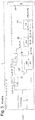
図3は、効率的なパラメトリック・オーディオエンコーダの詳細なブロック図である。
![]()
![]()
![]()
![]()
信号はその後、ダウンミキシングユニット5においてダウンミキシングされ、Mチャネルのダウンミキシング信号
![]()
![]()
![]()
![]()
空間パラメータは、サラウンドサウンド知覚を代表する心理音響学のキュー(cue)から構成される。例えば、これらのパラメータは、送信されるダウンミキシング信号
![]()
![]()
![]()
![]()
![]()
![]()
![]()
![]()
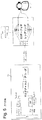
受信側では、メインビットストリームがデコードされ、受信された空間パラメータを使用して高品質なマルチチャネルの表現が合成される。メインビットストリームは最初にMチャネルのオーディオデコーダ31においてデコードされ、ここから、デコード信号
![]()
![]()
![]()
![]()
![]()
![]()
![]()
![]()
マルチチャネル・サラウンドサウンドについてのパーソナライズされた3Dオーディオレンダリングは、例えば図4を参照して上述したマルチチャネル・デコーダを使用して最初に複数のサラウンドサウンド・チャネルを取得する効率的なパラメトリック・サラウンドデコーダを使用することにより、移動端末のユーザへと伝達可能である。その後、バイノーラルの3Dオーディオレンダリングされたマルチチャネル信号を合成するために図1に示すシステムが使用される。この動作を図5の概略図に示す。 Personalized 3D audio rendering for multi-channel surround sound is an efficient parametric surround decoder that first obtains multiple surround sound channels using, for example, the multi-channel decoder described above with reference to FIG. Can be transmitted to the user of the mobile terminal. The system shown in FIG. 1 is then used to synthesize a binaural 3D audio rendered multi-channel signal. This operation is shown in the schematic diagram of FIG.
サブバンド領域において空間フィルタリング或いは3Dオーディオフィルタリングを実行する作業も行われている。C.A. Lanciani, and R. W. Schafer, "Application of Head-related Transfer Functions to MPEG Audio Signals", Proc. 31st Symposium on System Theory, March 21-23, 1999, Auburn, AL, U.S.A.は、サブバンド領域においてHRフィルタリング動作を実行することによってMPEG符号化されたモノラル信号をどのようにして空間化することができるかを開示している。A. B. Touimi, M. Emerit and J. M. Pernaux, "Efficient Method for Multiple Compressed Audio Streams Spatialization," Proc. 3rd International Conference on Mobile and Ubiquitous Multimedia, pp. 229-235, October 27-29, 2004, College Park, Maryland, U.S.A.は、スババンド領域において頭部関連(HR)フィルタリングを行うことによって個別にMPEG符号化された多数のモノラル信号をどのようにして空間化することができるかを開示している。このソリューションはHRフィルタの空間的実装に基づいており、全てのHRフィルタは、いくつかの事前定義された基準フィルタの線形結合としてモデル化されている。 Work to perform spatial filtering or 3D audio filtering in the subband region is also being performed. CA Lanciani, and RW Schafer, "Application of Head-related Transfer Functions to MPEG Audio Signals", Proc. 31st Symposium on System Theory, March 21-23, 1999, Auburn, AL, USA It is disclosed how an MPEG-encoded monaural signal can be spatialized by executing. AB Touimi, M. Emerit and JM Pernaux, "Efficient Method for Multiple Compressed Audio Streams Spatialization," Proc. 3rd International Conference on Mobile and Ubiquitous Multimedia, pp. 229-235, October 27-29, 2004, College Park, Maryland, USA discloses how multiple monaural signals that are individually MPEG encoded can be spatialized by performing head-related (HR) filtering in the subband region. This solution is based on a spatial implementation of the HR filter, and all HR filters are modeled as a linear combination of several predefined reference filters.
3Dオーディオレンダリングのアプリケーションは多様であり、おしゃべり(gamming)、3GPP MBMSやDVB−Hなどの標準を使用したモバイルTVショー、音楽コンサートの鑑賞、映画の視聴、及び、概してマルチチャネル・オーディオコンポーネントを含むマルチメディアサービスが含まれる。 Applications for 3D audio rendering are diverse, including gamming, mobile TV shows using standards such as 3GPP MBMS and DVB-H, watching music concerts, watching movies, and generally multi-channel audio components Includes multimedia services.
マルチチャネル・サラウンドサウンドをレンダリングする上述の方法は、無線移動ユニットに対して完全に新しいサービスセットを提供することを可能にするので魅力的であるが、多くの欠点を有する。 While the above method of rendering multi-channel surround sound is attractive because it allows a completely new set of services to be provided to a wireless mobile unit, it has many drawbacks.
第1に、デコードと3Dレンダリングとを並行してリアルタイムに実行しなければならないので、そのようなレンダリングに関する計算上の要件は極めて高い。パラメトリック・マルチチャネル・デコーダの複雑性は、全波形マルチチャネル・デコーダと比べれば低いかもしれないが、依然として極めて高く、少なくとも単純なステレオデコーダよりも高い。空間デコーディングの合成ステージは、エンコードチャネルの数に少なくとも比例する複雑性を有する。加えて、3Dレンダリングのフィルタリング動作も、チャネルの数に比例する。 First, since decoding and 3D rendering must be performed in real time in parallel, the computational requirements for such rendering are very high. The complexity of a parametric multichannel decoder may be low compared to a full waveform multichannel decoder, but is still very high, at least higher than a simple stereo decoder. The synthesis stage of spatial decoding has a complexity that is at least proportional to the number of encoding channels. In addition, the filtering operation of 3D rendering is also proportional to the number of channels.
第2の欠点は、中間デコードチャネルを格納するために必要とされるテンポラリメモリに関する。3Dレンダリングの第2のステージで必要なので、これらのチャネルは実際にバッファリングされる。 The second drawback relates to the temporary memory required to store the intermediate decode channel. These channels are actually buffered because they are needed in the second stage of 3D rendering.
最後に、主要な欠点のうちの1つは、チャネル間の相関がキャンセルされるかもしれないという事実が原因で、そのような3Dオーディオレンダリングの品質が極めて限定されたものとなり得ることである。チャネル間の相関は、パラメトリック・マルチチャネル・コーディングが信号を合成する方法に起因して、不可欠なものである。 Finally, one of the major drawbacks is that the quality of such 3D audio rendering can be very limited due to the fact that the correlation between channels may be canceled. Correlation between channels is essential due to the way parametric multi-channel coding combines signals.
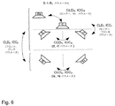
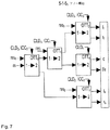
MPEGサラウンドでは、例えば、相関(ICC)及びチャネルレベル差(CLD)は、チャネルのペアの間でしか推定されない。ICCパラメータ及びCLDパラメータは、エンコードされてデコーダへと送信される。デコーダでは、受信したパラメータは、1つの5−1−5構成(本例では、5−1−51構成)について図7に描写するような合成ツリーにおいて使用される。図6は、5−1−51パラメータ化を有するサラウンドシステムの構成を示す。図6から、5−1−51構成におけるCLDパラメータ及びICCパラメータがチャネルのペアの間でのみ推定されることが見られる。 In MPEG surround, for example, correlation (ICC) and channel level difference (CLD) are only estimated between channel pairs. The ICC parameter and the CLD parameter are encoded and transmitted to the decoder. At the decoder, the received parameters are used in a synthesis tree as depicted in FIG. 7 for one 5-1-5 configuration (in this example, 5-1-5 1 configuration). FIG. 6 shows the configuration of a surround system with 5-1-5 one parameterization. From FIG. 6, it can be seen that the CLD and ICC parameters in the 5-1-5 1 configuration are only estimated between channel pairs.
相関(ICC)及びチャネルレベル差(CLD)がチャネルのペアの間でしか推定されないことが原因で、1つ1つの相関全てが得られる訳ではない。その結果、例えば3Dレンダリングとして、個別のチャネルの操作や再利用が妨げられる。事実、例えばRF及びRSという2つの非コーディングチャネルに例えば相関が無く、5−1−51構成を使用してこれらをエンコードする場合、これらの相関に対する制御を行うことができない。というのも、相関はそれ自体としてはデコーダへ送信されることはなく、ツリーの第2レベルでの相関のみが提供されるからである。デコーダ側では、これは2つの相関のあるデコードチャネルという結果に到る。事実デコーダは、ある個別のチャネル間の相関にアクセスできないし、制御することもできない。これらのチャネルは別々の第3レベルのボックスに属する。図6の例では、これらは全て、別々のスピーカ分類に属するチャネルのペアである。このことは図7においても見られる。チャネルのペアは、5−1−51構成において別々の第3レベルのツリーボックス(OTT3,OTT4,OTT2)に属するものである。スピーカの環境において聴く場合にはこれは問題ではないかもしれない。しかしながら、3Dレンダリングにおけるようにチャネルが一緒に結合される場合には、これは問題となって、望まれざるチャネルのキャンセルや過剰な増幅を招来する可能性がある。 Not every correlation is obtained because correlation (ICC) and channel level difference (CLD) are only estimated between channel pairs. As a result, for example, as 3D rendering, operation and reuse of individual channels are hindered. In fact, two non-coding channels, e.g. RF and RS, have no correlation, for example, and if they are encoded using the 5-1-5 1 configuration, there is no control over these correlations. This is because the correlation is not itself sent to the decoder, but only the correlation at the second level of the tree is provided. On the decoder side, this results in two correlated decode channels. In fact, the decoder cannot access or control the correlation between certain individual channels. These channels belong to separate third level boxes. In the example of FIG. 6, these are all channel pairs belonging to different speaker categories. This can also be seen in FIG. Channel pairs belong to separate third level tree boxes (OTT3, OTT4, OTT2) in a 5-1-5 1 configuration. This may not be a problem when listening in a speaker environment. However, when channels are combined together, as in 3D rendering, this can be a problem and can lead to unwanted channel cancellation and excessive amplification.
本発明の目的は、パラメトリック・マルチチャネル・デコーダにおける、所与のチャネルに関する望まれざるチャネルのキャンセル及び/又は(and/or)望まれざる増幅の可能性に関する欠点を克服することである。このことは、全チャネルの完全な共分散行列に到るために部分的に既知の共分散を外挿することによりデコードマルチチャネル信号の任意の線形結合をレンダリングし、外挿された共分散に基づいて、任意の線形結合の推定値を合成することにより、達成される。 It is an object of the present invention to overcome the drawbacks associated with the possibility of unwanted channel cancellation and / or unwanted amplification for a given channel in a parametric multi-channel decoder. This renders an arbitrary linear combination of the decoded multi-channel signal by extrapolating the partially known covariance to reach the complete covariance matrix of all channels, resulting in extrapolated covariance. Based on this, it is achieved by combining estimates of arbitrary linear combinations.
本発明の第1の態様によれば、マルチチャネル・サラウンドオーディオ信号の任意の所定の線形結合を合成する方法が提供される。本方法は、前記任意の所定の線形結合の記述Hを受信するステップと、前記マルチチャネル・サラウンドオーディオ信号のデコードされたダウンミキシング信号を受信するステップと、前記マルチチャネル・オーディオ信号の相関とチャネルレベル差とを含む空間パラメータを受信するステップと、前記マルチチャネル・オーディオ信号の相関とチャネルレベル差とを含む前記受信した空間パラメータに基づいて、部分的に既知の空間共分散を取得するステップと、完全な空間共分散を取得するために、前記部分的に既知の空間共分散を外挿するステップと、前記外挿された完全な空間共分散と、前記受信したデコードされたダウンミキシング信号と、前記任意の所定の線形結合の前記記述とに少なくとも基づいて、前記マルチチャネル・サラウンドオーディオ信号の前記任意の所定の線形結合の推定値を、忠実度の基準に従って形成するステップと、前記マルチチャネル・サラウンドオーディオ信号の前記任意の所定の線形結合の前記推定値に基づいて、マルチチャネル・サラウンドオーディオ信号の前記任意の所定の線形結合を合成するステップと、を備える。 According to a first aspect of the present invention, a method for synthesizing any predetermined linear combination of a multi-channel surround audio signal is provided. The method comprises receiving the arbitrary predetermined linear combination description H, receiving a decoded downmix signal of the multi-channel surround audio signal, correlation of the multi-channel audio signal and channel Receiving a spatial parameter including a level difference; obtaining a partially known spatial covariance based on the received spatial parameter including a correlation of the multi-channel audio signal and a channel level difference; Extrapolating the partially known spatial covariance to obtain a complete spatial covariance, the extrapolated complete spatial covariance, and the received decoded downmixing signal; , At least based on the description of the arbitrary predetermined linear combination, Forming an estimate of the arbitrary predetermined linear combination of the round audio signal according to fidelity criteria, and based on the estimate of the arbitrary predetermined linear combination of the multi-channel surround audio signal, Synthesizing said arbitrary predetermined linear combination of channel surround audio signals.
本発明の第2の態様によれば、マルチチャネル・サラウンドオーディオ信号の任意の所定の線形結合を合成する装置が提供される。本装置は、前記マルチチャネル・オーディオ信号の相関とチャネルレベル差とを含む受信した空間パラメータに基づいて、部分的に既知の空間共分散を取得する相関器と、完全な空間共分散を取得するために、前記部分的に既知の空間共分散を外挿する外挿器と、前記外挿された完全な空間共分散と、受信したデコードされたダウンミキシング信号と、前記任意の所定の線形結合を与える係数の記述とに少なくとも基づいて、前記マルチチャネル・サラウンドオーディオ信号の前記任意の所定の線形結合の推定値を、忠実度の基準に従って形成する推定器と、前記マルチチャネル・サラウンドオーディオ信号の前記任意の所定の線形結合の前記推定値に基づいて、マルチチャネル・サラウンドオーディオ信号の前記任意の所定の線形結合を合成する合成器と、を備える。 According to a second aspect of the invention, an apparatus for synthesizing any predetermined linear combination of multi-channel surround audio signals is provided. The apparatus obtains a partial spatial covariance and a correlator that obtains a partially known spatial covariance based on received spatial parameters including the correlation of the multi-channel audio signal and a channel level difference. An extrapolator that extrapolates the partially known spatial covariance, the extrapolated complete spatial covariance, the received decoded downmixing signal, and the arbitrary predetermined linear combination And an estimator that forms an estimate of the arbitrary predetermined linear combination of the multi-channel surround audio signal according to a fidelity criterion based on a description of the coefficients that provides the multi-channel surround audio signal, Based on the estimate of the arbitrary predetermined linear combination, the arbitrary predetermined linear combination of multi-channel surround audio signals is combined. It comprises a combiner for, a.
従って、本発明は、パラメトリック・エンコーダによってエンコードされたサラウンドサウンドを移動デバイスにおいてレンダリングする単純で効率的な方法を可能にする。その利点には、直接マルチチャネル信号に対して3Dレンダリングを使用することによって得られるものに比べて、複雑性が緩和されること、及び、品質が向上することが含まれる。 The present invention thus enables a simple and efficient way to render surround sound encoded by a parametric encoder on a mobile device. Its advantages include reduced complexity and improved quality compared to those obtained by using 3D rendering directly on multi-channel signals.
特に、本発明は、マルチチャネル・サラウンドサウンドに関する任意のバイノーラルのデコードを可能にする。 In particular, the present invention allows arbitrary binaural decoding for multi-channel surround sound.
更なる利点は、作業が周波数領域において行われるために、システムの複雑性が緩和されることである。 A further advantage is that the complexity of the system is reduced because the work is done in the frequency domain.
更なる利点は、信号のデコーディングステップにおいて出力が直接得られるので、信号のサンプルをバッファリングする必要が無いことである。 A further advantage is that there is no need to buffer signal samples, since the output is obtained directly in the signal decoding step.
本発明の基本的な概念は、受信した空間パラメータに基づいてマルチチャネル・サラウンドサウンドの部分的に既知の空間共分散を取得し、取得した部分的に既知の空間共分散を外挿して完全な空間共分散を取得することである。そして、忠実度の基準に従って、マルチチャネル・サラウンドサウンドオーディオ信号に関する所定の任意の線形結合が、少なくとも外挿された完全な空間共分散と、受信したデコードダウンミキシング信号mと、所定の任意の線形結合の記述Hとに基づいて推定され、その推定に基づいてマルチチャネル・サラウンドオーディオ信号の所定の線形結合を合成することが可能になる。マルチチャネル・サラウンドオーディオ信号の所定の任意の線形結合は、例えば頭部関連フィルタリングやバイノーラルフィルタリングなどのマルチチャネル信号のフィルタリングの、概念上の表現となり得る。それは、反響などの他の音響効果も表現可能である。 The basic concept of the present invention is to obtain a partially known spatial covariance of multi-channel surround sound based on received spatial parameters and extrapolate the acquired partially known spatial covariance. To obtain the spatial covariance. Then, according to fidelity criteria, the predetermined arbitrary linear combination for the multi-channel surround sound audio signal is at least extrapolated complete spatial covariance, the received decoded downmixing signal m, and the predetermined arbitrary linear And a predetermined linear combination of the multi-channel surround audio signals can be synthesized based on the estimation. Any given linear combination of multi-channel surround audio signals can be a conceptual representation of multi-channel signal filtering such as head-related filtering or binaural filtering. It can also express other acoustic effects such as reverberations.
従って、本発明は、デコーダのための方法とデコーダのための装置とに関する。この装置が図10aに示されており、相関器902aと、外挿器902bと、推定器903と、合成器904とを備える。相関器902aは、マルチチャネル・サラウンドオーディオ信号の相関(ICC)とチャネルレベル差(CLD)とを含む受信した空間パラメータ901に基づいて、部分的に既知の空間共分散行列911を取得するように構成される。外挿器902bは、適切な外挿方法を使用して、完全な空間共分散行列を取得するために部分的に既知の空間共分散行列を外挿するように構成される。更に、推定器903は、受信したデコードダウンミキシング信号と、所定の任意の線形結合の記述を表現する係数である行列
![]()
![]()
MPEGサラウンドデコーダに関連して、本発明の好適な実施形態を説明する。なお、MPEGサラウンドデコーダを参照して本発明の好適な実施形態を説明するが、他のパラメトリックデコーダやパラメトリックシステムもまた本発明に関連した使用に適しているであろうことを理解されたい。 A preferred embodiment of the present invention will be described in the context of an MPEG surround decoder. While the preferred embodiment of the present invention is described with reference to an MPEG surround decoder, it should be understood that other parametric decoders and parametric systems may also be suitable for use in connection with the present invention.
本発明の本質から逸脱せずに単純化するために、図7に示す5−1−51MPEGサラウンド構成を考える。この構成は、接続された複数のOTT(one−to−two)ボックスを備える。チャネルレベル差(CLD)及び相関(ICC)と呼ばれる空間パラメータに関する、resのような付帯情報が、OTTボックスに入力される。mは、マルチチャネル信号のダウンミキシング信号である。 To simplify without departing from the essence of the present invention, consider the 5-1-5 1 MPEG Surround configuration shown in FIG. This configuration comprises a plurality of connected one-to-two (OTT) boxes. Accompanying information, such as res, about spatial parameters called channel level difference (CLD) and correlation (ICC) is entered into the OTT box. m is a downmixing signal of a multi-channel signal.
マルチチャネル信号の合成は、ハイブリッド周波数領域において行われる。この周波数分割は、ヒトの耳の時間−周波数分析をある程度真似ることを意図しており、非線形である。 Multi-channel signal synthesis is performed in the hybrid frequency domain. This frequency division is intended to mimic to some extent the time-frequency analysis of the human ear and is non-linear.
以下、全てのハイブリッド・サブバンドにはkというインデックスが付けられ、全てのタイムスロットにはnというインデックスが付けられる。ビットレートの要件を低くするために、MPEGサラウンド空間パラメータは、パラメータ・タイムスロットlと呼ばれるダウンサンプリング・タイムスロットと、処理バンドmと呼ばれるダウンサンプリング・ハイブリッド周波数領域とに関してのみ、定義される。nとlとの間の関係、及びmとkとの間の関係を、図8に示す。このように、周波数バンドm0は周波数バンドk0及びk1を含み、周波数バンドm1は周波数バンドk2及びk3を含む。また、タイムスロットlは、タイムスロットnをダウンサンプリングしたバージョンである。CLDパラメータ及びICCパラメータはそれゆえ、そのパラメータ・タイムスロット及び処理バンドにとって有効である。全ての処理パラメータが、全ての処理バンドについて算出され、続いて、全てのハイブリッドバンドにマッピングされる。その後、全ての処理パラメータが、パラメータ・タイムスロットから全てのタイムスロットnへと内挿される。
Hereinafter, all hybrid subbands are indexed k, and all time slots are indexed n. In order to lower the bit rate requirement, the MPEG Surround Spatial Parameters are defined only with respect to a downsampling time slot called parameter time slot l and a downsampling hybrid frequency domain called processing band m. The relationship between n and l and the relationship between m and k are shown in FIG. Thus, the frequency band m0 includes the frequency bands k0 and k1, and the frequency band m1 includes the frequency bands k2 and k3.
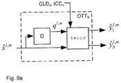
図7に示すデコーダのOTTボックスは、図9aに示すように視覚化することができる。 The OTT box of the decoder shown in FIG. 7 can be visualized as shown in FIG. 9a.
この図解に基づけば、任意のOTTボックスに関する出力は、2つの元のチャネル
![]()
![]()
![]()
![]()
![]()
![]()
![]()
![]()
エンコーダにおいて行われる推定パートの検査によって、このことをより良く理解することができるであろう。図9bに示すように、エンコーダは、OTTボックスを逆にしたものであるR−OTTボックスを含む。R−OTTボックスは、ステレオ信号を変換して、モノラル信号と、これに組み合わされる、各入力信号間の空間キューを表現するパラメータ抽出とにする。これらのR−OTTボックスそれぞれへの入力信号は、元のチャネル
![]()
![]()

![]()
![]()
そして、各R−OTTボックスは、次式の相互相関で示されるように、入力信号に関して対応する時間/周波数のタイルの同様の尺度を算出する(これは、「Inter−Channel Correlation」又はICCと記述される)。
加えて、R−OTTボックスは、下記のようにモノラル信号を生成する。
ここで、g0,g1は適切なゲインである。g0=g1=1/2であれば、モノラル信号が生成される。他の選択肢は、g0,g1を次のように選択することである。
以下、上の式が成立して、R−OTTxボックスの出力エネルギーが入力エネルギーの合計に等しいものとする。 Hereinafter, it is assumed that the above equation holds and the output energy of the R-OTTx box is equal to the total input energy.
R−OTTボックスに入力されるあらゆる2つのチャネル間の相関(ICC)及びチャネルレベル差(CLD)は、量子符号化されてデコーダへと送信される。 The correlation (ICC) and channel level difference (CLD) between any two channels input to the R-OTT box are quantum encoded and transmitted to the decoder.
本発明のこの実施形態は、空間共分散行列を構築するために、各(R)−OTTボックスに対応するCLD及びICCを使用するが、相関及びチャネルレベル差に関する他の尺度を使用してもよい。 This embodiment of the invention uses the CLD and ICC corresponding to each (R) -OTT box to construct the spatial covariance matrix, but other measures for correlation and channel level differences may be used. Good.
その結果、あらゆる2つのチャネル間の共分散行列は、下記のようになる。
MPEGサラウンドデコーダでは実数の相関のみを利用可能なので、一般性を失うことなく、実数の相関行列を仮定することができる。それゆえ、OTTボックスの各出力チャネル(これはR−OTTボックスへの入力である)は、下記の共分散行列を持つものとして示すことができる。
ここで、
OTT3及びOTT4の出力に対応するチャネルベクトルが
未知の2x2行列を「?」で示している。従って、空間パラメータCLD及びICCに基づいて、部分的に既知の空間共分散行列を取得することができる。 An unknown 2 × 2 matrix is indicated by “?”. Therefore, a partially known spatial covariance matrix can be obtained based on the spatial parameters CLD and ICC.
更に、OTT3及びOTT4の入力は相互に関連し、共分散行列
![]()
![]()
![]()
![]()
![]()
![]()
それゆえ、最初の4つのチャネルに関する共分散行列は、次のように記述することができる。
MPEGサラウンドの標準では、ρ4=ICC4の値は存在せず、1に等しいものとして概念的に仮定される。即ち、センターとLFEとは、倍率の係数を除けば同一である。しかしながら、汎用的な開発を行うために、この仮定は行わないものとする。 In the MPEG Surround standard, the value of ρ 4 = ICC 4 does not exist and is conceptually assumed to be equal to 1. That is, the center and the LFE are the same except for the magnification factor. However, this assumption is not made for general-purpose development.
最後の行列方程式は、多数の未知の空間チャネル間相関が存在するということを示す。即ち、
![]()
![]()
![]()
![]()
![]()
![]()
![]()
![]()
従って、失われている量が次式を満足しなければならないということが即座に理解できよう。
![]()
![]()
この制約単独では全ての失われた空間変数を決定することができないということも明らかである。 It is also clear that this constraint alone cannot determine all lost spatial variables.
個別のチャネルを更に操作するために、本発明のこの実施形態は、この相関合計の制約を維持したまま、失われた相関量を外挿する。なお、そのような行列を外挿することは、結果として得られる外挿行列が対称的で符号が正に定まるようなものでなければならない。これは事実、共分散行列として受容できるあらゆる行列に対する必要条件である。 In order to further manipulate the individual channels, this embodiment of the invention extrapolates the lost correlation amount while maintaining this correlation sum constraint. Note that extrapolation of such a matrix must be such that the resulting extrapolation matrix is symmetric and the sign is positive. This is in fact a requirement for any matrix that can be accepted as a covariance matrix.
完全な共分散行列を取得するために部分的に既知の共分散行列を外挿するために、いくつかの技術を文献から使用することができる。ある方法やその他の方法を使用することは、本発明の範囲内である。 Several techniques can be used from the literature to extrapolate a partially known covariance matrix to obtain a complete covariance matrix. It is within the scope of the present invention to use certain methods and other methods.
好適な実施形態によれば、外挿法として最大エントロピー原理を使用する。このことは容易な実装につながり、オーディオ品質という点で極めて良好な性能を示す。 According to a preferred embodiment, the maximum entropy principle is used as an extrapolation method. This leads to easy implementation and very good performance in terms of audio quality.
従って、外挿される相関量は、共分散行列の行列式を最大化するように、即ち次式のように、選択される。
![]()
![]()
これは凸最適化問題であり、閉形式解(closed form solution)が存在する。表記を単純化するために、汎用共分散行列のためのソリューションを導入する。
最初に、Γの行列式を最大化することは、下記の行列の行列式を最大化することと同等でもあるということに注意されたい。
これはまた、センターチャネル(C及びLFE)及びフロントチャネル(FL及びFR)から取得される、モノラルチャネル及びサイドチャネルの共分散行列を評価することとも同等であり、即ち次式の通りである。
ここで明らかなように、行列Γに関する制約は容易に次式のように変換される。
残りの未知の相関は
![]()
![]()
![]()
![]()
![]()
![]()
これらの量はそれゆえ、入手可能なデータから極めて容易に外挿可能である。最後に、完全な外挿された共分散行列Γについて、以下のように単純な行列乗算が必要である。
これらのステップは、更なる2つのチャネル、即ちLS及びRSの全体の共分散行列を外挿するためにも適用される。次式のように、全体が外挿された共分散行列が導かれる。
同じアプローチを用いることにより、即ち複数のチャネルを仮想的なモノラルチャネルとサイドチャネルとに変換することにより、外挿される共分散行列のための閉形式の式を導出することは極めて容易である。 It is very easy to derive a closed form equation for the extrapolated covariance matrix by using the same approach, i.e. by transforming multiple channels into virtual mono and side channels.
ここまでで提案してきたのは、チャネル[lf rf c lfe]に関する部分的な共分散行列を最初に外挿してから全チャネルの全体の共分散行列を外挿するという、2ステップのアプローチである。しかしながら、全体の不完全な共分散行列を算出してから全ての相関を全体的に外挿するという、他のアプローチもあるだろう。この2つのアプローチは、概念的には同等である。しかしながら、2番目のアプローチはより効果的である。というのも、前者は2ステップのアプローチを暗示する一方で、2番目のアプローチは全ての可能性のある相関を全体的に外挿するからである。 What has been proposed so far is a two-step approach in which the partial covariance matrix for the channel [lf rf c lfe] is extrapolated first and then the entire covariance matrix for all channels is extrapolated. . However, there may be other approaches that compute the overall incomplete covariance matrix and then extrapolate all correlations globally. The two approaches are conceptually equivalent. However, the second approach is more effective. This is because the former implies a two-step approach, while the second approach globally extrapolates all possible correlations.
両方のアプローチは実装に関して類似しており、最大エントロピー(即ち、行列式の最大化)のアプローチに基づいている。 Both approaches are similar in implementation and are based on a maximum entropy (ie, determinant maximization) approach.
なお、全ての量は時間と周波数の両方に依存する。明瞭化のためにインデックスを付けることは省略した。時間のインデックスは、パラメータ・タイムスロットlに対応し、周波数のインデックスは処理バンドのインデックスmに対応する。最後に、結果として得られる全ての相関は、
![]()
![]()
![]()
![]()
以下、モノラルのダウンミキシングエネルギーの表記を単純化するために、正規化された外挿された共分散行列を以下のように定義する。
外挿された共分散行列に基づいて任意のチャネルを推定して合成することを以下に説明する。 The estimation and synthesis of an arbitrary channel based on the extrapolated covariance matrix will be described below.
元のチャネルの所定の任意の線形結合として定義される任意のチャネルが、例えば以下のようにデコード/合成されるものとする。
ここで、行列
![]()
![]()
![]()
![]()
![]()
![]()
![]()
![]()
これは、出力に関する品質を制限し、望まれないチャネルの相関を引き起こしたり、可能性として望まれないチャネルのキャンセルを引き起こしたりすることになろう。 This will limit the quality with respect to the output and cause undesired channel correlation or possibly undesired channel cancellation.
前述したように、各R−OTTボックスの出力は線形結合をもたらす。それゆえ、ダウンミキシング信号が実際に全てのチャネルの線形結合であるということは容易に理解できる。 As described above, the output of each R-OTT box provides a linear combination. Therefore, it can be easily understood that the downmixing signal is actually a linear combination of all channels.
![]()
![]()
係数である
![]()
![]()
![]()
![]()
モノラルのダウンミキシング信号
![]()
![]()
![]()
![]()
![]()
![]()
ここで、
![]()
![]()
![]()
![]()
![]()
![]()
その目標はそれゆえ、何らかの忠実度の基準(本事例では平均平方誤差基準)に関して誤差
![]()
![]()
この行列が静的であると仮定すれば、即ち、平均化の演算子からこの行列を除外できると仮定すれば、この問題に対する平均平方解は
![]()
![]()
行列
![]()
![]()
これは、前述したように、デコーダでは入手できないかもしれないが、先に述べた技法に従って外挿される。ここでは、共分散行列を複素数として示す。しかしながら、実数の相関のみが使用されるので、その結果は実数の共分散行列についても依然として有効であることを容易に示すことができる。 This, as mentioned above, may not be available at the decoder, but is extrapolated according to the technique described above. Here, the covariance matrix is shown as a complex number. However, since only real correlations are used, it can easily be shown that the results are still valid for real covariance matrices.
ここまでで示してきたのは、全てのハイブリッド・サブバンドkと全てのタイムスロットnとについて最小平均平方が推定されるということである。ある程度の数のタイムスロットについて平均平方の推定値を算出して、これを全てのタイムスロットに拡張するために外挿を用いれば、実際に、かなりの量の複雑性を減少させることができる。例えば、パラメータのために使用されるものと同じタイムスロットに対して推定値をマッピングすること、即ち、パラメータ・タイムスロットのインデックスlに対してのみ共分散行列を算出することは、有益である。複雑性の緩和に関する同様の技法は、パラメータ・バンドのインデックスmに対してのみ算出される平均平方推定値をマッピングすることによって使用することもできる。しかしながら、これは一般的には、時間のインデックスに対してするほどは直接的でない。というのも、行列
![]()
![]()
既に前述したように、共分散行列
![]()
![]()
![]()
![]()
なお、
![]()
![]()
![]()
![]()
![]()
![]()
![]()
![]()
最小平方推定値はその性質上、エネルギー損失を発生させるものであり、これは合成チャネルの品質に悪影響を与える可能性がある。エネルギー損失は、デコード信号に適用されるモデルと本当の信号との間の不適合に起因する。最小平方の技術用語では、これは雑音部分空間と呼ばれる。空間聴覚においては、この用語は、拡散音場と呼ばれる。即ち、マルチチャネル信号の一部が無相関(uncorrelated)であるか拡散している。これを回避するために、雑音部分空間及び拡散音場を満たしてそれによって望まれる信号に心理音響学的に近似する推定信号を取得するために、多数の非相関信号(decorrelated signals)が使用される。 The minimum square estimate is by nature a loss of energy that can adversely affect the quality of the composite channel. The energy loss is due to a mismatch between the model applied to the decoded signal and the real signal. In least square technical terms, this is called the noise subspace. In spatial hearing, this term is called the diffuse sound field. That is, part of the multi-channel signal is uncorrelated or spread. To avoid this, a large number of decorrelated signals are used to obtain an estimated signal that fills the noise subspace and diffuse sound field and thereby psychoacoustically approximates the desired signal. The
最小平均平方の直交性質が原因で、望まれる信号のエネルギーは次式のように表現できる。
従って、l,m領域における誤差に関する正規化された共分散行列は、次式のように表現できる。
望まれる信号
![]()
![]()
![]()
![]()
![]()
![]()
![]()
![]()
![]()
![]()
![]()
![]()
誤差信号に近似する信号を生成する1つの方法は、モノラルのダウンミキシング信号に対して適用される非相関の使用を介するものである。これにより、誤差信号が平均平方推定値とは無相関になることが保証される。というのも、
![]()
![]()
これを行う単純な方法は、生成された非相関信号がそれら自体の間でも無相関なようにし、
![]()
![]()
![]()
![]()
![]()
![]()
しかしながら、
先行技術に従えば、これを確かにする単純な方法は、全通過フィルタリング非相関を使用することであり、こうして、(モノラルの信号エネルギーに関して)正規化された、
![]()
![]()
![]()
![]()
![]()
![]()
最後に、全体の合成は次式のように記述することができる。
![]()
![]()
ここで、行列
![]()
![]()
そして同様に、行列
![]()
![]()
![]()
![]()
図10bは、上述した本発明の実施形態に従って任意のチャネルを合成するために使用される装置を要約して示す。参照符号は、図10aのそれに対応する。本実施形態において、推定器903は、マルチチャネル・サラウンドオーディオ信号の推定線形結合とマルチチャネル・サラウンドオーディオ信号の任意の所定の線形結合との間の平均平方誤差(即ち、
![]()
![]()
また、推定器903は、マルチチャネル・サラウンドオーディオ信号の線形結合の推定値913を取得するために、
![]()
![]()
![]()
![]()
![]()
![]()
![]()
![]()
![]()
![]()
![]()
![]()
![]()
![]()
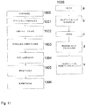
ここで図11に移ると、図11は、本発明の実施形態のフローチャートを示す。本方法は、以下のステップを備える。 Turning now to FIG. 11, FIG. 11 shows a flowchart of an embodiment of the present invention. The method comprises the following steps.
1000. 任意の所定の線形結合の記述Hを受信する。 1000. Receive a description H of any given linear combination.
1001. マルチチャネル・サラウンドオーディオ信号のデコードダウンミキシング信号を受信する。 1001. Receive a decode downmix signal of a multi-channel surround audio signal.
1002. マルチチャネル・オーディオ信号の相関とチャネルレベル差とを含む空間パラメータを受信する。 1002. Spatial parameters including the correlation of the multi-channel audio signal and the channel level difference are received.
1003. 受信した、マルチチャネル・オーディオ信号の相関とチャネルレベル差とを含む空間パラメータに基づいて、部分的に既知の空間共分散行列を取得する。 1003. A partially known spatial covariance matrix is obtained based on the received spatial parameters including the correlation of the multi-channel audio signal and the channel level difference.
1004. 部分的に既知の空間共分散行列を外挿して、完全な空間共分散行列を取得する。 1004. Extrapolate a partially known spatial covariance matrix to obtain a complete spatial covariance matrix.
1005. 外挿された完全な空間共分散行列と、受信したデコードダウンミキシング信号と、任意の所定の線形結合の前記記述とに少なくとも基づいて、マルチチャネル・サラウンドオーディオ信号の前記任意の所定の線形結合の推定値を、忠実度の基準に従って形成する。 1005. Of the arbitrary predetermined linear combination of the multi-channel surround audio signal based at least on the extrapolated complete spatial covariance matrix, the received decoded downmixing signal, and the description of the arbitrary predetermined linear combination. Estimates are formed according to fidelity criteria.
1006. マルチチャネル・サラウンドオーディオ信号の任意の所定の線形結合の前記推定値に基づいて、マルチチャネル・サラウンドオーディオ信号の前記任意の所定の線形結合を合成する。 1006. The arbitrary predetermined linear combination of the multi-channel surround audio signals is synthesized based on the estimated value of the arbitrary predetermined linear combination of the multi-channel surround audio signals.
ステップ1005は下記のステップを更に備えてもよい。
1005a. マルチチャネル・サラウンドオーディオ信号の推定線形結合と、マルチチャネル・サラウンドオーディオ信号の任意の所定の線形結合との間の、平均平方誤差を最小化することにより、行列Qを決定する。 1005a. The matrix Q is determined by minimizing the mean square error between the estimated linear combination of the multichannel surround audio signal and any predetermined linear combination of the multichannel surround audio signal.
1005b. Qにダウンミキシング信号を乗じて、マルチチャネル・サラウンドオーディオ信号の任意の所定の線形結合の推定値を取得する。 1005b. Multiply Q by the downmixing signal to obtain an estimate of any given linear combination of the multichannel surround audio signal.
1005c. 非相関信号の量を示す非相関信号形成行列Zを決定する。 1005c. A decorrelation signal formation matrix Z indicating the amount of decorrelation signals is determined.
1005d. 時間領域においてQ及びZを内挿する。 1005d. Interpolate Q and Z in the time domain.
1005e. ダウンサンプリング周波数バンドmをハイブリッドバンドkにマッピングする。 1005e. Map downsampling frequency band m to hybrid band k.
本方法は、移動端末のデコーダ内に実装することができる。 The method can be implemented in the decoder of the mobile terminal.
本発明は、上述した好適な実施形態に限定されない。多様な代替例、変形例、及び均等物を使用することができる。それゆえ、上述の実施形態は、本発明の範囲を限定するものとして捉えられてはならない。本発明の範囲は、添付の請求の範囲によって規定される。 The present invention is not limited to the preferred embodiments described above. Various alternatives, modifications, and equivalents can be used. Therefore, the above-described embodiments should not be taken as limiting the scope of the invention. The scope of the invention is defined by the appended claims.
<略語>
AAC Advanced Audio Coding
AMR−WB+ 拡張適応マルチレート・ワイドバンド
C センター
CLD チャネルレベル差
HR 頭部関連
HRF 頭部関連フィルタ
HRTF 頭部関連伝達関数
IC チャネル間コヒーレンス
ICC 相関
ILD チャネル間レベル差
ITD チャネル間時間差
L レフト
LFE 低周波要素
MPEG Moving Picture Experts Group
OTT One−to−two
PCM パルス符号変調
PDA 携帯情報端末
R ライト
R−OTT Reversed one−to−two
SL サラウンド・レフト
SR サラウンド・ライト
<Abbreviation>
AAC Advanced Audio Coding
AMR-WB + Extended adaptive multi-rate wideband C center CLD Channel level difference HR Head-related HRF Head-related filter HRTF Head-related transfer function IC Inter-channel coherence ICC correlation ILD Inter-channel level difference ITD Inter-channel time difference L Left LFE Low Frequency element MPEG Moving Picture Experts Group
OTT One-to-two
PCM pulse code modulation PDA portable information terminal R light R-OTT Reversed one-to-two
SL Surround Left SR Surround Right
Claims (20)
前記所定の線形結合の記述Hを受信するステップ(1000)と、
前記マルチチャネル・サラウンドオーディオ信号のデコードされたダウンミキシング信号を受信するステップ(1001)と、
前記マルチチャネル・サラウンドオーディオ信号の相関とチャネルレベル差とを含む空間パラメータを受信するステップ(1002)と、
前記マルチチャネル・サラウンドオーディオ信号の相関とチャネルレベル差とを含む前記受信した空間パラメータに基づいて、前記マルチチャネル・サラウンドオーディオ信号の部分的に既知の空間共分散行列を取得するステップ(1003)と、
前記マルチチャネル・サラウンドオーディオ信号の完全な空間共分散行列を取得するために、前記部分的に既知の空間共分散行列を外挿するステップ(1004)と、
前記外挿された完全な空間共分散行列と、前記受信したデコードされたダウンミキシング信号と、前記所定の線形結合の前記記述Hとに少なくとも基づいて、前記マルチチャネル・サラウンドオーディオ信号の前記所定の線形結合の推定を、忠実度の基準に従って形成するステップ(1005)と、
前記マルチチャネル・サラウンドオーディオ信号の前記所定の線形結合の推定に基づいて、マルチチャネル・サラウンドオーディオ信号の前記所定の線形結合を合成するステップ(1006)と、
を備えることを特徴とする方法。A method for synthesizing a predetermined linear combination of multi-channel surround audio signals, comprising:
Receiving (1000) a description H of said predetermined linear combination;
Receiving (1001) a decoded downmixing signal of the multi-channel surround audio signal;
Receiving (1002) a spatial parameter including a correlation of the multi-channel surround audio signal and a channel level difference;
Based on the spatial parameters to the received and a correlation and channel level differences of the multi-channel surround audio signal to obtain a partially known spatial covariance matrix of the multichannel surround audio signals and the step (1003) ,
To obtain a complete spatial covariance matrix of the multichannel surround audio signals, and the step (1004) extrapolating the partially known spatial covariance matrix,
And said extrapolated complete spatial covariance matrices, and downmixing signals decoded said received, at least based on said description H of the predetermined linear combination, said predetermined of said multi-channel surround audio signal Forming a linear combination estimate according to fidelity criteria (1005) ;
Synthesizing (1006) the predetermined linear combination of the multi-channel surround audio signal based on the estimation of the predetermined linear combination of the multi-channel surround audio signal;
A method comprising the steps of:
前記マルチチャネル・サラウンドオーディオ信号の前記線形結合の推定と、前記マルチチャネル・サラウンドオーディオ信号の前記所定の線形結合との間の、平均平方誤差を最小化することにより、行列Qを決定するステップと、
マルチチャネル・サラウンドオーディオ信号の前記所定の線形結合の推定を取得するために、前記行列Qに前記ダウンミキシング信号を乗じるステップと、
を更に備えることを特徴とする請求項1に記載の方法。The forming step includes
An estimation of the linear combination of the multichannel surround audio signals, between said predetermined linear combination of the multichannel surround audio signals by minimizing a mean square error, determining a matrix Q ,
Multiplying the matrix Q by the downmixing signal to obtain an estimate of the predetermined linear combination of multi-channel surround audio signals;
The method of claim 1, further comprising:
Q*m+Z*「非相関信号」
を実行するステップを備える、ことを特徴とする請求項3に記載の方法。The combining step is performed for each frequency band and each time slot to compensate for energy loss.
Q * m + Z * “Decorrelated signal”
The method of claim 3, comprising the step of:
ダウンサンプリングされた周波数バンドmをハイブリッドバンドkにマッピングするステップと、
を更に備えることを特徴とする請求項5に記載の方法。Interpolating the matrix Q in the time domain;
Mapping the downsampled frequency band m to the hybrid band k;
The method of claim 5, further comprising:
ダウンサンプリングされた周波数バンドmをハイブリッドバンドkにマッピングするステップと、
を更に備えることを特徴とする請求項6に記載の方法。Interpolating the matrix Z in the time domain;
Mapping the downsampled frequency band m to the hybrid band k;
The method of claim 6 further comprising:
前記マルチチャネル・サラウンドオーディオ信号の相関とチャネルレベル差とを含む受信した空間パラメータに基づいて、部分的に既知の空間共分散行列を取得する相関器と、
前記マルチチャネル・サラウンドオーディオ信号の完全な空間共分散行列を取得するために、前記部分的に既知の空間共分散行列を外挿する外挿器と、
前記外挿された完全な空間共分散行列と、受信したデコードされたダウンミキシング信号と、前記所定の線形結合を与える係数の記述を表現するHとに少なくとも基づいて、前記マルチチャネル・サラウンドオーディオ信号の前記所定の線形結合の推定を、忠実度の基準に従って形成する推定器と、
前記マルチチャネル・サラウンドオーディオ信号の前記所定の線形結合の推定に基づいて、マルチチャネル・サラウンドオーディオ信号の前記所定の線形結合を合成する合成器と、
を備えることを特徴とする装置。An apparatus for synthesizing a predetermined linear combination of multi-channel surround audio signals,
A correlator for obtaining a partially known spatial covariance matrix based on received spatial parameters including correlation and channel level difference of the multi-channel surround audio signal;
To obtain a complete spatial covariance matrix of the multichannel surround audio signals, extrapolating extrapolator the partially known spatial covariance matrix,
The multi-channel surround audio signal based at least on the extrapolated complete spatial covariance matrix , the received decoded downmixing signal, and H representing a description of the coefficients giving the predetermined linear combination An estimator that forms an estimate of said predetermined linear combination of according to fidelity criteria;
A synthesizer that synthesizes the predetermined linear combination of the multi-channel surround audio signals based on an estimate of the predetermined linear combination of the multi-channel surround audio signals;
A device comprising:
前記マルチチャネル・サラウンドオーディオ信号の前記線形結合の推定と、前記マルチチャネル・サラウンドオーディオ信号の前記所定の線形結合との間の、平均平方誤差を最小化することにより、行列Qを決定する手段と、
マルチチャネル・サラウンドオーディオ信号の前記所定の線形結合の推定を取得するために、前記行列Qに前記ダウンミキシング信号を乗じる手段と、
を更に備えることを特徴とする請求項11に記載の装置。The estimator is
An estimation of the linear combination of the multichannel surround audio signals, between said predetermined linear combination of the multichannel surround audio signals by minimizing a mean square error, means for determining a matrix Q ,
Means for multiplying the matrix Q by the downmixing signal to obtain an estimate of the predetermined linear combination of multi-channel surround audio signals;
The apparatus of claim 11, further comprising:
Q*m+Z*「非相関信号」
を実行する手段を備える、ことを特徴とする請求項13に記載の装置。The synthesizer is for each frequency band and each time slot to compensate for energy loss.
Q * m + Z * “Decorrelated signal”
14. The apparatus of claim 13, comprising means for performing
Applications Claiming Priority (3)
| Application Number | Priority Date | Filing Date | Title |
|---|---|---|---|
| US74387106P | 2006-03-28 | 2006-03-28 | |
| US60/743,871 | 2006-03-28 | ||
| PCT/SE2007/050194 WO2007111568A2 (en) | 2006-03-28 | 2007-03-28 | Method and arrangement for a decoder for multi-channel surround sound |
Publications (2)
| Publication Number | Publication Date |
|---|---|
| JP2009531735A JP2009531735A (en) | 2009-09-03 |
| JP4875142B2 true JP4875142B2 (en) | 2012-02-15 |
Family
ID=38541553
Family Applications (1)
| Application Number | Title | Priority Date | Filing Date |
|---|---|---|---|
| JP2009502725A Expired - Fee Related JP4875142B2 (en) | 2006-03-28 | 2007-03-28 | Method and apparatus for a decoder for multi-channel surround sound |
Country Status (6)
| Country | Link |
|---|---|
| US (1) | US8126152B2 (en) |
| EP (1) | EP2000001B1 (en) |
| JP (1) | JP4875142B2 (en) |
| CN (1) | CN101411214B (en) |
| AT (1) | ATE538604T1 (en) |
| WO (1) | WO2007111568A2 (en) |
Families Citing this family (44)
| Publication number | Priority date | Publication date | Assignee | Title |
|---|---|---|---|---|
| JP4988716B2 (en) | 2005-05-26 | 2012-08-01 | エルジー エレクトロニクス インコーポレイティド | Audio signal decoding method and apparatus |
| US8577686B2 (en) * | 2005-05-26 | 2013-11-05 | Lg Electronics Inc. | Method and apparatus for decoding an audio signal |
| EP1946297B1 (en) * | 2005-09-14 | 2017-03-08 | LG Electronics Inc. | Method and apparatus for decoding an audio signal |
| WO2007083959A1 (en) * | 2006-01-19 | 2007-07-26 | Lg Electronics Inc. | Method and apparatus for processing a media signal |
| CN104681030B (en) | 2006-02-07 | 2018-02-27 | Lg电子株式会社 | Apparatus and method for encoding/decoding signal |
| WO2008046530A2 (en) * | 2006-10-16 | 2008-04-24 | Fraunhofer-Gesellschaft zur Förderung der angewandten Forschung e.V. | Apparatus and method for multi -channel parameter transformation |
| MX2009003570A (en) * | 2006-10-16 | 2009-05-28 | Dolby Sweden Ab | Enhanced coding and parameter representation of multichannel downmixed object coding. |
| KR101061129B1 (en) * | 2008-04-24 | 2011-08-31 | 엘지전자 주식회사 | Method of processing audio signal and apparatus thereof |
| EP2144230A1 (en) | 2008-07-11 | 2010-01-13 | Fraunhofer-Gesellschaft zur Förderung der angewandten Forschung e.V. | Low bitrate audio encoding/decoding scheme having cascaded switches |
| CN102124516B (en) * | 2008-08-14 | 2012-08-29 | 杜比实验室特许公司 | Audio signal transformatting |
| CN101673545B (en) * | 2008-09-12 | 2011-11-16 | 华为技术有限公司 | Method and device for coding and decoding |
| JP5758902B2 (en) * | 2009-10-16 | 2015-08-05 | フラウンホッファー−ゲゼルシャフト ツァ フェルダールング デァ アンゲヴァンテン フォアシュンク エー.ファオ | Apparatus, method, and computer for providing one or more adjusted parameters using an average value for providing a downmix signal representation and an upmix signal representation based on parametric side information related to the downmix signal representation program |
| EP2323130A1 (en) | 2009-11-12 | 2011-05-18 | Koninklijke Philips Electronics N.V. | Parametric encoding and decoding |
| JP5645951B2 (en) * | 2009-11-20 | 2014-12-24 | フラウンホッファー−ゲゼルシャフト ツァ フェルダールング デァ アンゲヴァンテン フォアシュンク エー.ファオ | An apparatus for providing an upmix signal based on a downmix signal representation, an apparatus for providing a bitstream representing a multichannel audio signal, a method, a computer program, and a multi-channel audio signal using linear combination parameters Bitstream |
| CN102859590B (en) | 2010-02-24 | 2015-08-19 | 弗劳恩霍夫应用研究促进协会 | Produce the device strengthening lower mixed frequency signal, the method producing the lower mixed frequency signal of enhancing and computer program |
| US9313598B2 (en) | 2010-03-02 | 2016-04-12 | Nokia Technologies Oy | Method and apparatus for stereo to five channel upmix |
| KR101666465B1 (en) * | 2010-07-22 | 2016-10-17 | 삼성전자주식회사 | Apparatus method for encoding/decoding multi-channel audio signal |
| US8908874B2 (en) | 2010-09-08 | 2014-12-09 | Dts, Inc. | Spatial audio encoding and reproduction |
| KR101697550B1 (en) * | 2010-09-16 | 2017-02-02 | 삼성전자주식회사 | Apparatus and method for bandwidth extension for multi-channel audio |
| KR20120038311A (en) * | 2010-10-13 | 2012-04-23 | 삼성전자주식회사 | Apparatus and method for encoding and decoding spatial parameter |
| US8675881B2 (en) * | 2010-10-21 | 2014-03-18 | Bose Corporation | Estimation of synthetic audio prototypes |
| US9078077B2 (en) | 2010-10-21 | 2015-07-07 | Bose Corporation | Estimation of synthetic audio prototypes with frequency-based input signal decomposition |
| KR20140027954A (en) | 2011-03-16 | 2014-03-07 | 디티에스, 인코포레이티드 | Encoding and reproduction of three dimensional audio soundtracks |
| KR20120128542A (en) * | 2011-05-11 | 2012-11-27 | 삼성전자주식회사 | Method and apparatus for processing multi-channel de-correlation for cancelling multi-channel acoustic echo |
| EP2560161A1 (en) | 2011-08-17 | 2013-02-20 | Fraunhofer-Gesellschaft zur Förderung der angewandten Forschung e.V. | Optimal mixing matrices and usage of decorrelators in spatial audio processing |
| US9799339B2 (en) | 2012-05-29 | 2017-10-24 | Nokia Technologies Oy | Stereo audio signal encoder |
| BR112015028337B1 (en) | 2013-05-16 | 2022-03-22 | Koninklijke Philips N.V. | Audio processing apparatus and method |
| EP2830336A3 (en) | 2013-07-22 | 2015-03-04 | Fraunhofer-Gesellschaft zur Förderung der angewandten Forschung e.V. | Renderer controlled spatial upmix |
| EP3022949B1 (en) | 2013-07-22 | 2017-10-18 | Fraunhofer Gesellschaft zur Förderung der angewandten Forschung E.V. | Multi-channel audio decoder, multi-channel audio encoder, methods, computer program and encoded audio representation using a decorrelation of rendered audio signals |
| EP2830051A3 (en) | 2013-07-22 | 2015-03-04 | Fraunhofer-Gesellschaft zur Förderung der angewandten Forschung e.V. | Audio encoder, audio decoder, methods and computer program using jointly encoded residual signals |
| EP2830333A1 (en) | 2013-07-22 | 2015-01-28 | Fraunhofer-Gesellschaft zur Förderung der angewandten Forschung e.V. | Multi-channel decorrelator, multi-channel audio decoder, multi-channel audio encoder, methods and computer program using a premix of decorrelator input signals |
| TWI671734B (en) | 2013-09-12 | 2019-09-11 | 瑞典商杜比國際公司 | Decoding method, encoding method, decoding device, and encoding device in multichannel audio system comprising three audio channels, computer program product comprising a non-transitory computer-readable medium with instructions for performing decoding m |
| US9779739B2 (en) | 2014-03-20 | 2017-10-03 | Dts, Inc. | Residual encoding in an object-based audio system |
| WO2016003206A1 (en) * | 2014-07-01 | 2016-01-07 | 한국전자통신연구원 | Multichannel audio signal processing method and device |
| US9883308B2 (en) | 2014-07-01 | 2018-01-30 | Electronics And Telecommunications Research Institute | Multichannel audio signal processing method and device |
| US9774974B2 (en) * | 2014-09-24 | 2017-09-26 | Electronics And Telecommunications Research Institute | Audio metadata providing apparatus and method, and multichannel audio data playback apparatus and method to support dynamic format conversion |
| MY179448A (en) | 2014-10-02 | 2020-11-06 | Dolby Int Ab | Decoding method and decoder for dialog enhancement |
| EP3007167A1 (en) * | 2014-10-10 | 2016-04-13 | Thomson Licensing | Method and apparatus for low bit rate compression of a Higher Order Ambisonics HOA signal representation of a sound field |
| ES2955962T3 (en) | 2015-09-25 | 2023-12-11 | Voiceage Corp | Method and system using a long-term correlation difference between the left and right channels for time-domain downmixing of a stereo sound signal into primary and secondary channels |
| GB201718341D0 (en) | 2017-11-06 | 2017-12-20 | Nokia Technologies Oy | Determination of targeted spatial audio parameters and associated spatial audio playback |
| GB2572650A (en) | 2018-04-06 | 2019-10-09 | Nokia Technologies Oy | Spatial audio parameters and associated spatial audio playback |
| GB2574239A (en) | 2018-05-31 | 2019-12-04 | Nokia Technologies Oy | Signalling of spatial audio parameters |
| BR112021025265A2 (en) * | 2019-06-14 | 2022-03-15 | Fraunhofer Ges Forschung | Audio synthesizer, audio encoder, system, method and non-transient storage unit |
| EP4229630A1 (en) * | 2020-10-13 | 2023-08-23 | Fraunhofer-Gesellschaft zur Förderung der angewandten Forschung e.V. | Apparatus and method for encoding a plurality of audio objects using direction information during a downmixing or apparatus and method for decoding using an optimized covariance synthesis |
Citations (9)
| Publication number | Priority date | Publication date | Assignee | Title |
|---|---|---|---|---|
| WO2004019656A2 (en) * | 2001-02-07 | 2004-03-04 | Dolby Laboratories Licensing Corporation | Audio channel spatial translation |
| US20050157883A1 (en) * | 2004-01-20 | 2005-07-21 | Jurgen Herre | Apparatus and method for constructing a multi-channel output signal or for generating a downmix signal |
| US20060060278A1 (en) * | 2004-09-17 | 2006-03-23 | Youji Noguchi | Pneumatic tire |
| US20060085200A1 (en) * | 2004-10-20 | 2006-04-20 | Eric Allamanche | Diffuse sound shaping for BCC schemes and the like |
| WO2006132857A2 (en) * | 2005-06-03 | 2006-12-14 | Dolby Laboratories Licensing Corporation | Apparatus and method for encoding audio signals with decoding instructions |
| WO2007016107A2 (en) * | 2005-08-02 | 2007-02-08 | Dolby Laboratories Licensing Corporation | Controlling spatial audio coding parameters as a function of auditory events |
| EP1761110A1 (en) * | 2005-09-02 | 2007-03-07 | Ecole Polytechnique Fédérale de Lausanne | Method to generate multi-channel audio signals from stereo signals |
| WO2007089129A1 (en) * | 2006-02-03 | 2007-08-09 | Electronics And Telecommunications Research Institute | Apparatus and method for visualization of multichannel audio signals |
| JP2009508432A (en) * | 2005-09-14 | 2009-02-26 | エルジー エレクトロニクス インコーポレイティド | Audio signal decoding method and apparatus |
Family Cites Families (7)
| Publication number | Priority date | Publication date | Assignee | Title |
|---|---|---|---|---|
| CN1139300C (en) * | 1997-05-20 | 2004-02-18 | 日本胜利株式会社 | System for processing audio surround signal |
| EP1054575A3 (en) * | 1999-05-17 | 2002-09-18 | Bose Corporation | Directional decoding |
| US7254239B2 (en) * | 2001-02-09 | 2007-08-07 | Thx Ltd. | Sound system and method of sound reproduction |
| KR100522593B1 (en) * | 2002-07-08 | 2005-10-19 | 삼성전자주식회사 | Implementing method of multi channel sound and apparatus thereof |
| DE102004042819A1 (en) * | 2004-09-03 | 2006-03-23 | Fraunhofer-Gesellschaft zur Förderung der angewandten Forschung e.V. | Apparatus and method for generating a coded multi-channel signal and apparatus and method for decoding a coded multi-channel signal |
| DE602005017302D1 (en) * | 2004-11-30 | 2009-12-03 | Agere Systems Inc | SYNCHRONIZATION OF PARAMETRIC ROOM TONE CODING WITH EXTERNALLY DEFINED DOWNMIX |
| US7606716B2 (en) * | 2006-07-07 | 2009-10-20 | Srs Labs, Inc. | Systems and methods for multi-dialog surround audio |
-
2007
- 2007-03-28 US US12/295,172 patent/US8126152B2/en not_active Expired - Fee Related
- 2007-03-28 JP JP2009502725A patent/JP4875142B2/en not_active Expired - Fee Related
- 2007-03-28 EP EP07716149A patent/EP2000001B1/en active Active
- 2007-03-28 WO PCT/SE2007/050194 patent/WO2007111568A2/en active Application Filing
- 2007-03-28 CN CN200780011012.2A patent/CN101411214B/en active Active
- 2007-03-28 AT AT07716149T patent/ATE538604T1/en active
Patent Citations (9)
| Publication number | Priority date | Publication date | Assignee | Title |
|---|---|---|---|---|
| WO2004019656A2 (en) * | 2001-02-07 | 2004-03-04 | Dolby Laboratories Licensing Corporation | Audio channel spatial translation |
| US20050157883A1 (en) * | 2004-01-20 | 2005-07-21 | Jurgen Herre | Apparatus and method for constructing a multi-channel output signal or for generating a downmix signal |
| US20060060278A1 (en) * | 2004-09-17 | 2006-03-23 | Youji Noguchi | Pneumatic tire |
| US20060085200A1 (en) * | 2004-10-20 | 2006-04-20 | Eric Allamanche | Diffuse sound shaping for BCC schemes and the like |
| WO2006132857A2 (en) * | 2005-06-03 | 2006-12-14 | Dolby Laboratories Licensing Corporation | Apparatus and method for encoding audio signals with decoding instructions |
| WO2007016107A2 (en) * | 2005-08-02 | 2007-02-08 | Dolby Laboratories Licensing Corporation | Controlling spatial audio coding parameters as a function of auditory events |
| EP1761110A1 (en) * | 2005-09-02 | 2007-03-07 | Ecole Polytechnique Fédérale de Lausanne | Method to generate multi-channel audio signals from stereo signals |
| JP2009508432A (en) * | 2005-09-14 | 2009-02-26 | エルジー エレクトロニクス インコーポレイティド | Audio signal decoding method and apparatus |
| WO2007089129A1 (en) * | 2006-02-03 | 2007-08-09 | Electronics And Telecommunications Research Institute | Apparatus and method for visualization of multichannel audio signals |
Also Published As
| Publication number | Publication date |
|---|---|
| ATE538604T1 (en) | 2012-01-15 |
| CN101411214A (en) | 2009-04-15 |
| JP2009531735A (en) | 2009-09-03 |
| WO2007111568A3 (en) | 2007-12-13 |
| WO2007111568A2 (en) | 2007-10-04 |
| US20090110203A1 (en) | 2009-04-30 |
| US8126152B2 (en) | 2012-02-28 |
| EP2000001A2 (en) | 2008-12-10 |
| EP2000001B1 (en) | 2011-12-21 |
| CN101411214B (en) | 2011-08-10 |
Similar Documents
| Publication | Publication Date | Title |
|---|---|---|
| JP4875142B2 (en) | Method and apparatus for a decoder for multi-channel surround sound | |
| CN103489449B (en) | Audio signal decoder, method for providing upmix signal representation state | |
| JP4944902B2 (en) | Binaural audio signal decoding control | |
| JP5227946B2 (en) | Filter adaptive frequency resolution | |
| CN101433099A (en) | Personalized decoding of multi-channel surround sound | |
| RU2520359C2 (en) | Acoustic echo suppressing device and front-end conference call device | |
| KR101358700B1 (en) | Audio encoding and decoding | |
| US8880413B2 (en) | Binaural spatialization of compression-encoded sound data utilizing phase shift and delay applied to each subband | |
| CN111970630B (en) | Audio decoder and decoding method | |
| Villemoes et al. | MPEG Surround: the forthcoming ISO standard for spatial audio coding | |
| JP2009522895A (en) | Decoding binaural audio signals | |
| JP2008543227A (en) | Reconfiguration of channels with side information | |
| AU2005324210A1 (en) | Compact side information for parametric coding of spatial audio | |
| EA034936B1 (en) | Audio encoding and decoding using presentation transform parameters | |
| JP2023536156A (en) | Apparatus, method and computer program for encoding audio signals or decoding encoded audio scenes | |
| US20210250717A1 (en) | Spatial audio Capture, Transmission and Reproduction | |
| CN102027535A (en) | Processing of signals | |
| Plogsties et al. | MPEG Sorround binaural rendering-Sorround sound for mobile devices (Binaurale Wiedergabe mit MPEG Sorround-Sorround sound fuer mobile Geraete) | |
| EA047653B1 (en) | AUDIO ENCODING AND DECODING USING REPRESENTATION TRANSFORMATION PARAMETERS |
Legal Events
| Date | Code | Title | Description |
|---|---|---|---|
| A131 | Notification of reasons for refusal |
Free format text: JAPANESE INTERMEDIATE CODE: A131 Effective date: 20110624 |
|
| A521 | Request for written amendment filed |
Free format text: JAPANESE INTERMEDIATE CODE: A523 Effective date: 20110920 |
|
| TRDD | Decision of grant or rejection written | ||
| A01 | Written decision to grant a patent or to grant a registration (utility model) |
Free format text: JAPANESE INTERMEDIATE CODE: A01 Effective date: 20111118 |
|
| A01 | Written decision to grant a patent or to grant a registration (utility model) |
Free format text: JAPANESE INTERMEDIATE CODE: A01 |
|
| A61 | First payment of annual fees (during grant procedure) |
Free format text: JAPANESE INTERMEDIATE CODE: A61 Effective date: 20111124 |
|
| FPAY | Renewal fee payment (event date is renewal date of database) |
Free format text: PAYMENT UNTIL: 20141202 Year of fee payment: 3 |
|
| R150 | Certificate of patent or registration of utility model |
Ref document number: 4875142 Country of ref document: JP Free format text: JAPANESE INTERMEDIATE CODE: R150 Free format text: JAPANESE INTERMEDIATE CODE: R150 |
|
| R250 | Receipt of annual fees |
Free format text: JAPANESE INTERMEDIATE CODE: R250 |
|
| R250 | Receipt of annual fees |
Free format text: JAPANESE INTERMEDIATE CODE: R250 |
|
| R250 | Receipt of annual fees |
Free format text: JAPANESE INTERMEDIATE CODE: R250 |
|
| R250 | Receipt of annual fees |
Free format text: JAPANESE INTERMEDIATE CODE: R250 |
|
| R250 | Receipt of annual fees |
Free format text: JAPANESE INTERMEDIATE CODE: R250 |
|
| LAPS | Cancellation because of no payment of annual fees |