JP4874810B2 - X-ray CT system - Google Patents
X-ray CT system Download PDFInfo
- Publication number
- JP4874810B2 JP4874810B2 JP2006547829A JP2006547829A JP4874810B2 JP 4874810 B2 JP4874810 B2 JP 4874810B2 JP 2006547829 A JP2006547829 A JP 2006547829A JP 2006547829 A JP2006547829 A JP 2006547829A JP 4874810 B2 JP4874810 B2 JP 4874810B2
- Authority
- JP
- Japan
- Prior art keywords
- image
- region
- contrast
- unit
- ray
- Prior art date
- Legal status (The legal status is an assumption and is not a legal conclusion. Google has not performed a legal analysis and makes no representation as to the accuracy of the status listed.)
- Expired - Fee Related
Links
- 238000012545 processing Methods 0.000 claims description 38
- 239000002872 contrast media Substances 0.000 claims description 34
- 210000004204 blood vessel Anatomy 0.000 claims description 24
- 238000000605 extraction Methods 0.000 claims description 13
- 230000005484 gravity Effects 0.000 claims description 12
- 238000006073 displacement reaction Methods 0.000 claims description 6
- 150000002632 lipids Chemical class 0.000 claims description 6
- 239000000284 extract Substances 0.000 claims description 5
- 230000008859 change Effects 0.000 claims description 4
- OYPRJOBELJOOCE-UHFFFAOYSA-N Calcium Chemical compound [Ca] OYPRJOBELJOOCE-UHFFFAOYSA-N 0.000 claims description 2
- 229910052791 calcium Inorganic materials 0.000 claims description 2
- 239000011575 calcium Substances 0.000 claims description 2
- 238000005315 distribution function Methods 0.000 claims 1
- 238000000034 method Methods 0.000 description 28
- 238000010586 diagram Methods 0.000 description 15
- 230000008569 process Effects 0.000 description 13
- 239000000126 substance Substances 0.000 description 12
- 238000006243 chemical reaction Methods 0.000 description 3
- 238000013480 data collection Methods 0.000 description 3
- 239000000463 material Substances 0.000 description 3
- 238000012546 transfer Methods 0.000 description 3
- 238000010521 absorption reaction Methods 0.000 description 2
- 230000002308 calcification Effects 0.000 description 2
- 239000003086 colorant Substances 0.000 description 2
- 239000000470 constituent Substances 0.000 description 2
- 210000004351 coronary vessel Anatomy 0.000 description 2
- 238000012937 correction Methods 0.000 description 2
- 238000001514 detection method Methods 0.000 description 2
- 230000004069 differentiation Effects 0.000 description 2
- 230000006372 lipid accumulation Effects 0.000 description 2
- 230000017531 blood circulation Effects 0.000 description 1
- 238000002591 computed tomography Methods 0.000 description 1
- 238000009792 diffusion process Methods 0.000 description 1
- 238000012986 modification Methods 0.000 description 1
- 230000004048 modification Effects 0.000 description 1
- 238000010606 normalization Methods 0.000 description 1
- 238000007781 pre-processing Methods 0.000 description 1
- 230000004044 response Effects 0.000 description 1
- 230000035945 sensitivity Effects 0.000 description 1
Images


Classifications
-
- A—HUMAN NECESSITIES
- A61—MEDICAL OR VETERINARY SCIENCE; HYGIENE
- A61B—DIAGNOSIS; SURGERY; IDENTIFICATION
- A61B5/00—Measuring for diagnostic purposes; Identification of persons
- A61B5/02—Detecting, measuring or recording pulse, heart rate, blood pressure or blood flow; Combined pulse/heart-rate/blood pressure determination; Evaluating a cardiovascular condition not otherwise provided for, e.g. using combinations of techniques provided for in this group with electrocardiography or electroauscultation; Heart catheters for measuring blood pressure
- A61B5/02007—Evaluating blood vessel condition, e.g. elasticity, compliance
-
- A—HUMAN NECESSITIES
- A61—MEDICAL OR VETERINARY SCIENCE; HYGIENE
- A61B—DIAGNOSIS; SURGERY; IDENTIFICATION
- A61B6/00—Apparatus for radiation diagnosis, e.g. combined with radiation therapy equipment
- A61B6/48—Diagnostic techniques
- A61B6/481—Diagnostic techniques involving the use of contrast agents
-
- A—HUMAN NECESSITIES
- A61—MEDICAL OR VETERINARY SCIENCE; HYGIENE
- A61B—DIAGNOSIS; SURGERY; IDENTIFICATION
- A61B6/00—Apparatus for radiation diagnosis, e.g. combined with radiation therapy equipment
- A61B6/50—Clinical applications
- A61B6/504—Clinical applications involving diagnosis of blood vessels, e.g. by angiography
-
- G—PHYSICS
- G06—COMPUTING; CALCULATING OR COUNTING
- G06T—IMAGE DATA PROCESSING OR GENERATION, IN GENERAL
- G06T11/00—2D [Two Dimensional] image generation
- G06T11/003—Reconstruction from projections, e.g. tomography
- G06T11/008—Specific post-processing after tomographic reconstruction, e.g. voxelisation, metal artifact correction
-
- G—PHYSICS
- G06—COMPUTING; CALCULATING OR COUNTING
- G06T—IMAGE DATA PROCESSING OR GENERATION, IN GENERAL
- G06T5/00—Image enhancement or restoration
- G06T5/20—Image enhancement or restoration by the use of local operators
-
- G06T5/75—
-
- G—PHYSICS
- G06—COMPUTING; CALCULATING OR COUNTING
- G06T—IMAGE DATA PROCESSING OR GENERATION, IN GENERAL
- G06T7/00—Image analysis
- G06T7/0002—Inspection of images, e.g. flaw detection
- G06T7/0012—Biomedical image inspection
-
- G—PHYSICS
- G06—COMPUTING; CALCULATING OR COUNTING
- G06T—IMAGE DATA PROCESSING OR GENERATION, IN GENERAL
- G06T7/00—Image analysis
- G06T7/10—Segmentation; Edge detection
- G06T7/11—Region-based segmentation
-
- G—PHYSICS
- G06—COMPUTING; CALCULATING OR COUNTING
- G06T—IMAGE DATA PROCESSING OR GENERATION, IN GENERAL
- G06T7/00—Image analysis
- G06T7/40—Analysis of texture
-
- A—HUMAN NECESSITIES
- A61—MEDICAL OR VETERINARY SCIENCE; HYGIENE
- A61B—DIAGNOSIS; SURGERY; IDENTIFICATION
- A61B6/00—Apparatus for radiation diagnosis, e.g. combined with radiation therapy equipment
- A61B6/02—Devices for diagnosis sequentially in different planes; Stereoscopic radiation diagnosis
- A61B6/03—Computerised tomographs
- A61B6/032—Transmission computed tomography [CT]
-
- G—PHYSICS
- G06—COMPUTING; CALCULATING OR COUNTING
- G06T—IMAGE DATA PROCESSING OR GENERATION, IN GENERAL
- G06T2207/00—Indexing scheme for image analysis or image enhancement
- G06T2207/30—Subject of image; Context of image processing
- G06T2207/30004—Biomedical image processing
-
- G—PHYSICS
- G06—COMPUTING; CALCULATING OR COUNTING
- G06T—IMAGE DATA PROCESSING OR GENERATION, IN GENERAL
- G06T2211/00—Image generation
- G06T2211/40—Computed tomography
- G06T2211/404—Angiography
Description
本発明は、被検体にX線を曝射して得られた投影データに基づいて被検体内部の画像を生成するX線CT装置及び画像処理装置に関する。 The present invention relates to an X-ray CT apparatus and an image processing apparatus that generate an image inside a subject based on projection data obtained by exposing the subject to X-rays.
X線CT装置の進歩は目覚しく、より高精細(高解像度)且つ広範囲に撮影したいという医療現場からの強い要望に応えて、近年、マルチスライスX線CT装置が開発され、これがかなり普及してきている。このマルチスライスX線CT装置は、スライス方向(寝台の長手方向)に広がり幅を有するファンビームX線を曝射するX線源と、複数列(4列、8列、16列など)の検出素子列をスライス方向に並べた構造の2次元検出器とを備え、これをマルチスキャン又はヘリカルスキャンで動作させるスキャナである。これにより、シングルスライスX線CT装置に比べて、被検体の広範囲にわたるボリュームデータを高精度に且つ短時間のうちに得ることができる。 In recent years, multi-slice X-ray CT apparatus has been developed and has become quite popular in response to the strong demand from the medical field that it is desired to take images with higher definition (high resolution) and a wider range. . This multi-slice X-ray CT apparatus detects an X-ray source that emits a fan beam X-ray having a spread in the slice direction (longitudinal direction of the bed) and a plurality of rows (4 rows, 8 rows, 16 rows, etc.). The scanner includes a two-dimensional detector having a structure in which element rows are arranged in the slice direction, and operates by multi-scanning or helical scanning. Thereby, compared with a single slice X-ray CT apparatus, volume data over a wide range of the subject can be obtained with high accuracy and in a short time.
このようなX線CT装置により生成されたCT画像中の血管は、近傍に高コントラスト物質(高いX線減弱係数を有する物質)がある場合、そのボケの影響を受けて、血管内腔の様子が不鮮明になる。従来、高コントラスト領域の影響を受けずに注目領域の画質を改善する方法として、高コントラスト領域のCT値を周囲のCT値に合わせた適当な値に設定してから画像処理し、その後、高コントラスト領域の値を戻すという方法が知られている。しかし、この方法では、高コントラスト領域周辺のボケを良好に除去することはできなかった(特開平10−40372号公報参照)。 When a blood vessel in a CT image generated by such an X-ray CT apparatus has a high-contrast material (a material having a high X-ray attenuation coefficient) in the vicinity, the state of the blood vessel lumen is affected by the blur. Becomes unclear. Conventionally, as a method of improving the image quality of a region of interest without being affected by the high contrast region, image processing is performed after setting the CT value of the high contrast region to an appropriate value that matches the surrounding CT value, and then high processing is performed. A method of returning the value of the contrast region is known. However, with this method, the blur around the high-contrast region could not be removed satisfactorily (see Japanese Patent Laid-Open No. 10-40372).
本発明の目的は、X線CT装置により得られた被検体内部のX線吸収分布画像を表示する場合に、高いX線減弱係数の物体の周辺に生じるボケを低減することにある。 An object of the present invention is to reduce blurring generated around an object having a high X-ray attenuation coefficient when an X-ray absorption distribution image inside a subject obtained by an X-ray CT apparatus is displayed.
本発明の第1局面は、被検体に関する投影データを収集し、前記収集した投影データに基づいて前記被検体の内部の画像を再構成するX線CT装置において、前記画像から、X線減弱係数の比較的高い高コントラスト領域を抽出するように構成されたユニットと、前記抽出した高コントラスト領域の位置と装置固有の点像強度分布関数とに基づいて、前記高コントラスト領域に関するボケ画像を発生するように構成されたユニットと、X線減弱係数の比較的低い低コントラスト領域に関する低コントラスト画像を発生するために、前記画像から前記ボケ画像を引き算するように構成されたユニットとを具備するX線CT装置を提供する。 According to a first aspect of the present invention, in an X-ray CT apparatus that collects projection data relating to a subject and reconstructs an image inside the subject based on the collected projection data, an X-ray attenuation coefficient is obtained from the image. A blur image related to the high contrast region is generated based on a unit configured to extract a relatively high high contrast region, a position of the extracted high contrast region, and a point spread function specific to the apparatus. X-ray comprising a unit configured as described above and a unit configured to subtract the blurred image from the image to generate a low-contrast image for a low-contrast region with a relatively low X-ray attenuation coefficient A CT apparatus is provided.
本発明の第2局面は、被検体に関する投影データを収集し、前記収集した投影データに基づいて前記被検体の内部の画像を再構成するX線CT装置において、X線減弱係数の比較的低い領域に関する低コントラスト画像を発生するために、前記画像から、前記画像に含まれるX線減弱係数の比較的高い領域に関するボケ画像を引き算するユニットと、前記低コントラスト画像をCT値に応じて複数の領域に分類するユニットと、前記低コントラスト画像の画素値を、前記分類した複数の領域各々に固有の値に置き換えるユニットとを具備するX線CT装置を提供する。 According to a second aspect of the present invention, in an X-ray CT apparatus that collects projection data related to a subject and reconstructs an image inside the subject based on the collected projection data, the X-ray attenuation coefficient is relatively low. A unit for subtracting from the image a blurred image relating to a region having a relatively high X-ray attenuation coefficient included in the image in order to generate a low-contrast image relating to the region; There is provided an X-ray CT apparatus comprising a unit for classifying into regions and a unit for replacing pixel values of the low-contrast image with values unique to the plurality of classified regions.
本発明の第3局面は、被検体に関する投影データを収集し、前記収集した投影データに基づいて前記被検体の内部の画像を再構成するX線CT装置において、前記画像から、複数の閾値に基づいて、順番に内包するサイズの異なる複数の領域候補を抽出するユニットと、前記抽出された複数の領域候補各々の重心を計算するユニットと、前記重心間の距離に基づいて、前記抽出された複数の領域候補から特定の領域を選択するユニットとを具備するX線CT装置を提供する。 According to a third aspect of the present invention, there is provided an X-ray CT apparatus that collects projection data relating to a subject and reconstructs an image inside the subject based on the collected projection data. Based on a unit for extracting a plurality of area candidates of different sizes included in order, a unit for calculating the centroid of each of the extracted plurality of area candidates, and the extracted based on the distance between the centroids An X-ray CT apparatus including a unit for selecting a specific area from a plurality of area candidates is provided.
(第1実施例)
以下、本発明の第1実施例について説明する。
図1は、第1実施例に係るX線CT装置の構成図である。X線CT装置1は、被検体に関する投影データを収集するために構成された架台2、被検体Pを載せて移動させるための寝台3、X線CT装置の操作するための入力及び画像表示を行うための操作コンソールを備えている。(First embodiment)
The first embodiment of the present invention will be described below.
FIG. 1 is a configuration diagram of an X-ray CT apparatus according to the first embodiment. The
架台1は、X線管5とX線検出器6を有する。X線管5とX線検出器6は、架台駆動装置7により回転駆動されるリング状の回転フレーム8に搭載される。寝台3は、被検体を載せる天板8、天板8を移動させるための天板駆動装置9を備えている。回転フレーム8はその中央部分に開口を有する。その開口に天板8に載置された被検体Pが挿入される。なお、回転フレーム8の回転中心軸をZ軸(スライス方向軸)、Z軸に直交する平面をXYの直交2軸で定義する。 The
X線管5の陰極陽極間には高電圧発生器10から管電圧が印加される。X線管5のフィラメントには高電圧発生器10からフィラメント電流が供給される。管電圧の印加及びフィラメント電流の供給によりX線が発生される。X線検出器6には、1次元アレイ型検出器又は2次元アレイ型検出器(マルチスライス型検出器ともいう)が採用される。X線検出素子は例えば0.5mm×0.5mmの正方の受光面を有する。例えば916個のX線検出素子がチャンネル方向に配列される。この列がスライス方向に例えば40列並設されたものが2次元アレイ型検出器である。単一の列からなるものが1次元アレイ型検出器である。 A tube voltage is applied from the
データ収集装置11は、一般的にDAS(data acquisition system)と呼ばれている。データ収集装置11は、検出器6からチャンネルごとに出力される信号を電圧信号に変換し、増幅し、さらにディジタル信号に変換する。このデータ(生データ)は架台外部の操作コンソール4に供給される。 The data collection device 11 is generally called a DAS (data acquisition system). The data collection device 11 converts the signal output from the detector 6 for each channel into a voltage signal, amplifies it, and further converts it into a digital signal. This data (raw data) is supplied to the operation console 4 outside the gantry.
操作コンソール4の前処理部12は、データ収集装置11から出力されるデータ(生データ)に対して感度補正等の補正処理を施して投影データを出力する。この投影データは再構成処理部13に送られる。再構成処理部13は、例えばヘリカルスキャン、コーンビームX線を使ったボリュームスキャン又はそれらの併用により収集された投影データに基づいて、画像データを再構成し、画像記憶部14に記憶する。画像処理部15は、画像記憶部14に記憶された画像データに基づいて表示画像を生成する。画像を表示するための条件の設定、関心領域の設定等は、操作者による入力装置16への入力に基づいて行われる。画像処理部の詳細は後述する。表示装置17は、画像処理部15で生成された画像を表示する。又、操作コンソール4のスキャン制御部18は、操作者の入力に基づいて、ヘリカルスキャン等のスキャンが行われるように、高圧発生装置10、架台駆動装置7、データ収集装置11、天板駆動装置9を制御する。尚、操作コンソール4は、専用ハードウェアで構成しても良いし、コンピュータを用いてソフトウェアで同様の機能を実現しても良い。 The preprocessing
図2は、図1の画像処理部15の構成を説明する図である。尚、図2の(A)は、画像処理対象の一例としての血管断面構造の模式図である。血管壁P1、ステントP2、造影剤(血流部分)P3、脂質P4を含んでいる。以下、このような実体の画像を処理した場合を例として説明する。 FIG. 2 is a diagram illustrating the configuration of the
画像処理部15は、関心領域設定・画像抽出部19、高コントラスト抽出部20、コンボリューション部21、CT値スケーリング部22、減算器23、加算器24を備えている。 The
関心領域設定・画像抽出部19は、入力装置16への入力に基づいて関心領域を設定し、その関心領域の画像データを画像記憶部14から抽出して出力する。図2の(B)は、関心領域設定・画像抽出部19により抽出された関心領域の画像を表している。 The region-of-interest setting /
高コントラスト抽出部20は、抽出部19により抽出された関心領域の画像から、X線減弱係数の非常に高い高コントラスト領域、つまり非常に高いCT値を有する画素群を抽出する。高コントラスト物質としては、治療のために被検体内に埋め込まれたステント等の金属性の器具、石灰化したカルシウム等がある。なお、後述するステント等を除外した低コントラスト画像における高コントラスト物質としては、ステント等ではなく、主に造影剤を対象としている。ステントと血管壁との間のCT値を有する造影剤が選択的に使用される。 The high
具体的な抽出処理としては、注目画素の値と、その注目画素周辺の複数画素の値の平均値との差分を求めることにより入力された画像の微分画像を求め、この微分画像に対してステントの辺縁に対応する閾値を用いて閾値処理を施すことにより、2値化画像を得る。この2値化画像は、高コントラスト物質が存在するであろう部分と、それ以外の部分で画素値が異なる画像となる。つまり、この2値化画像は、高コントラスト物質が存在するであろう位置の情報を含んだ画像(以下、高コントラスト位置画像という。)となる。図2の(C)は、この高コントラスト位置画像を表している。この微分・2値化処理では、比較的少ない演算処理で容易に高コントラスト位置画像を得ることができる。 As a specific extraction process, a differential image of an input image is obtained by obtaining a difference between the value of the target pixel and the average value of a plurality of pixels around the target pixel. A binarized image is obtained by performing threshold processing using a threshold corresponding to the edge of the image. This binarized image is an image in which pixel values are different between a portion where a high-contrast material will exist and other portions. That is, the binarized image is an image including information on a position where a high contrast substance will exist (hereinafter referred to as a high contrast position image). FIG. 2C shows this high contrast position image. In this differentiation / binarization processing, a high-contrast position image can be easily obtained with relatively little arithmetic processing.
コンボリューション部21は、高コントラスト位置画像に対して、当該X線コンピュータ断層撮影装置固有の点像強度分布関数(PSF:point spread function)を畳み込み演算をする。PSFは、装置固有のボケ特性を定義する関数として伝達関数又はボケ関数とも呼ばれる。PSFは、検出器6の検出器ピッチ(解像限界)である例えば0.5mmより微小な例えばその1/10の径(0.05mm)を有するワイヤファントムをスキャンし、その投影データから再構成により得られたワイヤファントムに関する2次元画像(ボケ画像)のデータとして得られる。このPSFを高コントラスト位置画像に畳み込むことにより、高コントラスト対象をそれ単独でスキャンして取得したデータから再構成した画像、つまり高コントラスト対象とその周辺に現れるボケとを含んだ画像が得られる。 The
CT値スケーリング部22は、コンボリューション部21から出力された画像(ボケ画像)を、CT値として特異でない値、つまりここでは造影剤としての標準的なCT値に従って規格化(スケール)する。この規格化処理は、後述する減算処理のための画素値のレベル合わせ処理である。図2の(D)は、CT値スケーリング部22から出力される画像(以下、高コントラスト画像という)を表している。 The CT
減算部23は、減算処理を行い、関心領域の画像と高コントラスト画像の差分画像を求める。これにより、関心領域の画像から高コントラスト物質及びその周辺のボケ成分が低減された低コントラスト画像が得られる。この低コントラスト画像は、低い減弱係数の物質を表した画像である。図2の(E)は、この低コントラスト画像を表している。 The
加算部24は、この低コントラスト画像に高コントラスト位置画像を加算することにより、高コントラスト物質の位置情報を加える。図2の(F)は、この出力画像を表している。この出力画像は、元の関心領域の画像から高コントラスト物質によるボケ(アーチファクト)を低減した画像に、高コントラスト物質の位置情報を加えたものであり、後段の処理を経て表示装置17に表示される。この出力画像では、元の画像ではボケの影響により識別困難だった高コントラスト物質周辺の脂質が良好に観察可能である。 The adding
このような第1実施例によれば、高コントラスト物質の周辺に生じるボケ成分を低減することができるため、高コントラスト物質周辺の物質を良好に観察できる。特に、心臓の冠状動脈のような3mmから5mmの径を有する細経血管にステントや石灰化がある場合において、その周辺の血管壁、脂質の蓄積状態、造影剤の状態等を良好に観察することが可能である。 According to the first embodiment, the blur component generated around the high contrast material can be reduced, so that the material around the high contrast material can be observed well. In particular, when there is a stent or calcification in a mesovascular vessel having a diameter of 3 mm to 5 mm, such as a coronary artery of the heart, the surrounding blood vessel wall, lipid accumulation state, contrast agent state, etc. are observed well. It is possible.
この第1実施例は種々変形して実施しても良い。例えば、上記実施例では、高コントラスト位置画像を加算したが、加算せずに低コントラスト画像のみの表示を行っても良い。又、高コントラスト物質の位置を示す色の異なるマークを重畳して表示するようにしても良い。 The first embodiment may be implemented with various modifications. For example, in the above embodiment, the high contrast position image is added, but only the low contrast image may be displayed without adding. In addition, marks of different colors indicating the position of the high contrast material may be superimposed and displayed.
さらに、上記実施例では、X線CT装置について説明したが、X線CT装置から出力された投影データ、CT画像等に基づいて画像の表示を行う医用画像処理装置で実施しても良い。さらに、上記実施例では2次元画像の処理について説明したが、複数の2次元画像に上述の処理を行うことにより3次元画像の処理を行うようにしても良い。 Furthermore, although the X-ray CT apparatus has been described in the above embodiments, the present invention may be implemented by a medical image processing apparatus that displays an image based on projection data, CT images, and the like output from the X-ray CT apparatus. Furthermore, in the above-described embodiment, the processing of the two-dimensional image has been described. However, the processing of the three-dimensional image may be performed by performing the above-described processing on a plurality of two-dimensional images.
さらに、上記実施例では画像の画素値がCT値である場合について説明したが、X線減弱係数を表すものであればCT値以外の値であっても良い。又、上記実施例では微分・2値化処理により高コントラスト位置画像を求めたが、高コントラスト物質によるボケを表した伝達関数を画像に逆コンボリューションして高コントラスト位置画像を求める方法や、ステントの位置・形状の情報を予め記憶しておきこの情報に基づいて位置情報を求める方法等を用いても良い。 Furthermore, although the case where the pixel value of the image is a CT value has been described in the above embodiment, any value other than the CT value may be used as long as it represents an X-ray attenuation coefficient. In the above embodiment, the high-contrast position image is obtained by the differentiation / binarization process. However, a method for obtaining the high-contrast position image by deconvolution of the transfer function representing the blur caused by the high-contrast material into the image, For example, a method for previously storing position / shape information and obtaining position information based on this information may be used.
(第2実施例)
以下、本発明の第2実施例について説明する。尚、第1実施例と同じ部分については説明を省略する。(Second embodiment)
The second embodiment of the present invention will be described below. The description of the same parts as those in the first embodiment is omitted.
第2実施例は、画像中の類似物質が識別し易くなるようにクラスタリング処理により、自動的に分類を行うものである。理想的な条件下では、プラークや脂質は−100から50のCT値、血管壁は50から129のCT値、血流に含まれる造影剤は130−350のCT値を示すことが知られている。しかしながら、実際の検査においては、被検体の体格、ビームハードニング、再構成関数、物質のサイズ、関心領域外の物質の状態、造影剤の濃度等の影響を受けて、CT値が変動している。このため領域抽出(領域分割)を行う方法では、このようなCT値の変動に対応できず、良好に分類することができない。本実施例では、低コントラスト画像から、主にプラークに対応する領域A、主に血管壁に対応する領域B、主に造影剤に対応する領域Cを高精度に抽出する。 In the second embodiment, classification is automatically performed by a clustering process so that similar substances in an image can be easily identified. Under ideal conditions, plaques and lipids are known to exhibit CT values between -100 and 50, vessel walls between 50 and 129, and contrast agents in the bloodstream between 130 and 350. Yes. However, in actual examinations, the CT value fluctuates due to the influence of the physique of the subject, beam hardening, reconstruction function, substance size, substance condition outside the region of interest, contrast agent concentration, etc. Yes. For this reason, the method of performing region extraction (region division) cannot cope with such a change in CT value and cannot be classified well. In this embodiment, a region A mainly corresponding to plaques, a region B mainly corresponding to blood vessel walls, and a region C mainly corresponding to contrast agents are extracted from the low contrast image with high accuracy.
図4は、第2実施例に係るX線CT装置1の構成図である。図4では、減算部23と加算部24の間にクラスタリング処理部25がある。このクラスタリング処理部25は、CT値に基づいて所定の複数の領域を求め、各領域が同一の輝度又は色で表示されるようにCT値の変換処理を行う。尚、本実施例では、CT値を3つの領域に分ける場合について説明するが、この領域の数は他の数でも良い。又、操作者の入力に応じて領域数を変更できるようにしても良い。 FIG. 4 is a configuration diagram of the
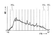
図5は、クラスタリンク処理部25の構成図である。クラスタリング処理部25は、ヒストグラム生成部26、領域決定部27、CT値変換部28を備えている。ヒストグラム生成部26は、入力された低コントラスト画像のヒストグラムを求める。ヒストグラムは、CT値ごとの画素出現の頻度分布を表している。ここではCT値は−100から537間での範囲に分布している。 FIG. 5 is a configuration diagram of the cluster
領域決定部27は、低コントラスト画像から、図6に示すように、例えば3つの領域A,B,Cを抽出する。領域Aは主にプラークに対応する。領域Bは主に血管壁に対応する。領域Cは主に造影剤に対応する。 The
図7は領域決定部27による低コントラスト画像から3つの領域A,B,Cを抽出する処理の手順を示している。まず、低コントラスト画像から血管壁領域Bを抽出する(S11)。操作者により指定された血管の略中心から放射状に複数の追跡線が設定される。各追跡線に沿ってCT値が追跡される。CT値の変動が比較的大きな位置、つまり所定値を超える微分値を示す2つの位置が血管壁の内点と外点として特定される。次に、低コントラスト画像からプラーク領域Aが抽出される(S12)。血管壁の内側であって血管壁よりも低いCT値を有する画素群が、プラーク領域Aとして抽出される。 FIG. 7 shows a procedure of processing for extracting three regions A, B, and C from the low contrast image by the
次に、造影剤の領域Cが抽出される(S13−S19)。まず、図8に例示するように、ヒストグラム上のCT値が分布する範囲(図6では−100から537までの範囲)が、k−means法により、N個のセグメントSEG1〜SEGNに分割される(S13)。CT値の最も高いセグメントを、SEG1とする。Nは最終的に分類される領域数n(ここではn=3)を超える整数に設定される。好ましくは、Nは最終的に分類される領域数nの2倍または3倍に設定される。mは処理変数である。mは1に初期化される。Next, a contrast medium region C is extracted (S13-S19). First, as illustrated in FIG. 8, the range in which CT values on the histogram are distributed (the range from −100 to 537 in FIG. 6) is divided into N segments SEG 1 to SEG N by the k-means method. (S13). The segment with the highest CT value is defined as SEG 1 . N is set to an integer exceeding the number n of regions finally classified (here, n = 3). Preferably, N is set to 2 or 3 times the number n of regions finally classified. m is a processing variable. m is initialized to 1.
まず、図9に示すように、セグメントSEG1に対応する領域候補R1が低コントラスト画像から抽出される(S14)。セグメントSEG1の最低値を閾値として領域R1が低コントラスト画像から抽出される。抽出された領域候補R1の重心位置B1が計算される(S15)。S17において変数mが1つインクリメントされる(S17)。なお、S18において、拡散防止のための停止条件として、“CTmin seg m<CTmax/2”が判断される。CTmin seg mはセグメントmの最小値であり、CTmaxは低コントラスト画像の最大CT値である。つまり、セグメントmの最小値が低コントラスト画像の最大CT値の1/2未満のとき、領域拡大処理が停止される。S18でNoのとき、S19が実行される。S18でYesのとき、S14に戻る。First, as shown in FIG. 9, the region candidate R 1 corresponding to the segment SEG 1 is extracted from the low contrast image (S14). Region R 1 is extracted from the low-contrast image with the lowest value of segment SEG 1 as a threshold. Center-of-gravity position B 1 of the extracted region candidate R 1 is calculated (S15). In S17, the variable m is incremented by one (S17). In S18, “CTmin seg m <CTmax / 2” is determined as a stop condition for preventing diffusion. CTmin seg m is the minimum value of the segment m, and CTmax is the maximum CT value of the low contrast image. That is, when the minimum value of the segment m is less than ½ of the maximum CT value of the low contrast image, the region enlargement process is stopped. If No in S18, S19 is executed. If Yes in S18, the process returns to S14.
図10に示すように、セグメントSEG1とセグメントSEG2とに対応する領域候補R2が低コントラスト画像から抽出される(S14)。実際には、セグメントSEG2の最低値を閾値として領域候補R2が低コントラスト画像から抽出される。抽出された領域候補R2の重心位置B2が計算される(S15)。この領域候補R2の重心位置B2と、一つ前の領域候補R1の重心位置B1との間の距離D2が計算され、所定の閾値Thと比較される(S16)。As shown in FIG. 10, the region candidate R 2 corresponding to the segment SEG 1 and the segment SEG 2 is extracted from the low contrast image (S14). Actually, the region candidate R 2 is extracted from the low-contrast image using the minimum value of the segment SEG 2 as a threshold value. Center-of-gravity position B 2 of the extracted region candidate R 2 is calculated (S15). A center-of-gravity position B 2 of the region candidate R 2, the distance D 2 between the center-of-gravity position B 1 of the previous region candidate R 1 is calculated and compared with a predetermined threshold value Th (S16).
S14〜S18の処理は、重心位置の変位量Dmが閾値Thを超過するまでループされる。つまり、変数mのインクリメントに従って領域候補Rは少しずつ拡大される。領域候補Rの拡大に伴って重心Bは変位する。抽出対象が同じときは重心Bの変位量は比較的少ない。抽出対象が他の物質を含むように拡大したとき、重心Bの変位量は比較的大きくなる。つまり、抽出対象が造影剤であるときは、領域候補Rが拡大しても、重心位置はあまり変化しない。しかし、抽出対象に血管壁等が加わったとき、領域候補Rは飛躍的に大きくなり、重心位置も大きく変化する。重心位置が大きく変化するセグメントが探索される。Processing S14~S18 are loops until displacement D m of center of gravity exceeds the threshold value Th. That is, the region candidate R is gradually expanded according to the increment of the variable m. As the area candidate R expands, the center of gravity B is displaced. When the extraction target is the same, the displacement amount of the center of gravity B is relatively small. When the extraction target is expanded to include other substances, the displacement amount of the center of gravity B is relatively large. That is, when the extraction target is a contrast medium, the position of the center of gravity does not change much even if the region candidate R is enlarged. However, when a blood vessel wall or the like is added to the extraction target, the region candidate R increases dramatically, and the position of the center of gravity changes greatly. A segment whose centroid position changes greatly is searched.
m=3において、図11に示すように、領域候補R3の重心位置B3と、一つ前の領域候補R2の重心位置B2との間の距離D3が閾値Thを超過したとき(S16)、一つ前の領域候補R2が造影剤の領域Cとして特定される(S19)。つまり重心の変位量が閾値Th未満に収まる最大の領域候補R2が特定の領域Cとして選択される。In m = 3, as shown in FIG. 11, the center-of-gravity position B 3 of area candidates R 3, when the distance D 3 between the center-of-gravity position B 2 of the previous region candidate R 2 exceeds the threshold value Th (S16), the previous region candidate R 2 is identified as an area C of the contrast medium (S19). That maximum area candidate R 2 amount of displacement of the center of gravity falls below the threshold Th is selected as the specific area C.
このように領域拡大による重心位置の変位に着目することで、CT値変動要因の影響をあまり受けずに、造影剤の領域Cを高精度に抽出することができる。また、血管壁抽出についても同様に、CT値変化に着目することで、CT値変動要因の影響をあまり受けずに、血管壁の領域Bを高精度に抽出することができる。さらに、プラーク抽出についても同様に、血管壁内側という条件を設定することにより、CT値変動要因の影響をあまり受けずに、プラークの領域Aを高精度に抽出することができる。 By paying attention to the displacement of the center of gravity position due to the region enlargement in this way, the region C of the contrast agent can be extracted with high accuracy without being greatly affected by the CT value variation factor. Similarly, regarding the blood vessel wall extraction, by focusing attention on the CT value change, the region B of the blood vessel wall can be extracted with high accuracy without being affected by the CT value variation factor. Furthermore, similarly for the plaque extraction, by setting the condition of the inside of the blood vessel wall, the plaque region A can be extracted with high accuracy without being greatly affected by the CT value variation factor.
なお、領域決定部27は、このヒストグラムを、k−mean法を用いて3つの領域に分類するようにしてもよい。k−mean法により、各領域内のCT値の分散値が等しくなるように、各領域を決めるための閾値Thを求める。各領域内のCT値の分散値が等しくなるよう各領域を決めることにより、類似性の高い物質が同じ領域内に含まれやすくなる。 The
図6は、本実施例により領域分けされた例を表しており、−100から537のCT値が3つの領域に分類されている。領域Aの範囲のCT値を持つ画素は主に脂質の部分に対応する。領域Bの範囲のCT値を持つ画素は主に血管壁の部分に対応する。領域Cの範囲のCT値を持つ画素は主にプラークの部分に対応する。 FIG. 6 shows an example of area division according to this embodiment, and CT values from −100 to 537 are classified into three areas. Pixels having CT values in the range of region A mainly correspond to lipid portions. Pixels having CT values in the range of region B mainly correspond to blood vessel wall portions. Pixels having CT values in the range of region C mainly correspond to the plaque portion.
CT値変換部28は、領域決定部27で抽出又は分類した3つの領域それぞれに含まれる画素のCT値を、予め設定された領域ごとの固有値に置き換える。それにより表示画像上で同じ領域部分が同一の輝度又は色で表示され、各領域が把握できる形態で表示される。 The CT
このような本実施例によれば、CT値に応じて領域分けされた画像が表示されるため、被検体内部の組織、脂質、造影剤等の異なる物質を良好に把握できる画像を提供することができる。又、領域を決めるための閾値をヒストグラムに基づいて自動的に求めているため、CT値の変動がある場合でも良好に分類した画像を提供することができる。 According to such a present Example, since the image segmented according to CT value is displayed, the image which can grasp | ascertain well different substances, such as a structure | tissue inside a subject, a lipid, a contrast agent, is provided. Can do. Further, since the threshold value for determining the region is automatically obtained based on the histogram, it is possible to provide a well-classified image even when the CT value varies.
又、この実施例では、高コントラスト物質の周辺に生じるボケ成分(アーチファクト成分)を低減させてから、低コントラスト画像を対象としてクラスタリング処理を行っているため、高コントラスト物質周辺の物質を良好に観察できる。特に、心臓の冠状動脈のような3mmから5mmの径を有する細経血管にステントや石灰化がある場合において、その周辺の血管壁、脂質の蓄積状態、造影剤の状態等を良好に観察することが可能である。 In this embodiment, the blur component (artifact component) generated around the high-contrast material is reduced, and then the clustering process is performed on the low-contrast image, so that the material around the high-contrast material can be observed well. it can. In particular, when there is a stent or calcification in a mesovascular vessel having a diameter of 3 mm to 5 mm, such as a coronary artery of the heart, the surrounding blood vessel wall, lipid accumulation state, contrast agent state, etc. are observed well. It is possible.
又、高コントラスト物質が含まれない画像に対してクラスタリング処理を行い、後から高コントラスト物質の情報を加えているため、低いCT値を有する部分の領域分けが良好にできる。 In addition, clustering processing is performed on an image that does not contain a high contrast material, and information on the high contrast material is added later, so that the region having a low CT value can be well divided.
尚、本発明は上記実施例に限定されるものではなく、実施段階ではその要旨を逸脱しない範囲で構成要素を変形して具体化できる。また、上記実施例に開示されている複数の構成要素の適宜な組み合わせにより、種々の発明を形成できる。例えば、実施例に示される全構成要素から幾つかの構成要素を削除してもよい。さらに、異なる実施例にわたる構成要素を適宜組み合わせてもよい。 In addition, this invention is not limited to the said Example, In an implementation stage, a component can be deform | transformed and embodied in the range which does not deviate from the summary. Various inventions can be formed by appropriately combining a plurality of constituent elements disclosed in the above embodiments. For example, some components may be deleted from all the components shown in the embodiments. Furthermore, constituent elements over different embodiments may be appropriately combined.
例えば、上記実施例では、k−mean法を用いて閾値を求めたが、群平均法、Ward法等の他のクラスタリング手法を用いて閾値を求めるようにしても良い。又、上記実施例では、高コントラスト物質及びその周辺のボケを除去した画像に対してクラスタリング処理を行ったが、このような処理をせず、関心領域の元画像に対して直接クラスタリング処理を行って表示画像を生成するようにしても良い。 For example, in the above embodiment, the threshold value is obtained by using the k-mean method, but the threshold value may be obtained by using another clustering method such as a group average method or a Ward method. In the above embodiment, the clustering process is performed on the image from which the high-contrast material and the surrounding blur are removed. However, the clustering process is directly performed on the original image of the region of interest without performing such a process. A display image may be generated.
さらに上記実施例では、高コントラスト位置画像を加算したが、加算せずに低コントラスト画像のみの表示を行っても良い。又、高コントラスト物質の位置を示す色の異なるマークを重畳して表示するようにしても良い。 Further, in the above embodiment, the high contrast position image is added, but only the low contrast image may be displayed without adding. In addition, marks of different colors indicating the position of the high contrast material may be superimposed and displayed.
さらに、上記実施例では、X線CT装置について説明したが、X線CT装置から出力された投影データCT画像等に基づいて画像の表示を行う医用画像処理装置で実施しても良い。さらに、上記実施例では、2次元画像の処理について説明したが、複数の2次元画像に上述の処理を行うことにより3次元画像の処理を行うようにしても良い。さらに、上記実施例では、画像の画素値がCT値である場合について説明したが、X線減弱係数を表すものであればCT値以外の値であっても良い。 Furthermore, although the X-ray CT apparatus has been described in the above embodiment, the present invention may be implemented by a medical image processing apparatus that displays an image based on projection data CT images output from the X-ray CT apparatus. Furthermore, in the above-described embodiment, the processing of the two-dimensional image has been described. However, the processing of the three-dimensional image may be performed by performing the above-described processing on a plurality of two-dimensional images. Furthermore, although the case where the pixel value of the image is a CT value has been described in the above embodiment, any value other than the CT value may be used as long as it represents an X-ray attenuation coefficient.
本発明によれば、X線CT装置により得られた被検体内部のX線吸収分布画像を表示する場合に、高いX線減弱係数の物体の周辺に生じるボケを低減することができる。 According to the present invention, when an X-ray absorption distribution image inside a subject obtained by an X-ray CT apparatus is displayed, blurring generated around an object having a high X-ray attenuation coefficient can be reduced.
Claims (14)
前記画像から、X線減弱係数の比較的高い高コントラスト領域を抽出するように構成されたユニットと、
前記抽出した高コントラスト領域の位置と装置固有の点像強度分布関数とに基づいて、前記高コントラスト領域に関するボケ画像を発生するように構成されたユニットと、
X線減弱係数の比較的低い低コントラスト領域に関する低コントラスト画像を発生するために、前記画像から前記ボケ画像を引き算するように構成されたユニットと、
前記低コントラスト画像をCT値に応じて複数の領域に分類するユニットと、
前記低コントラスト画像の画素値を、前記分類した複数の領域各々に固有の値に置き換えるユニットとを具備し、
前記分類した複数の領域には、脂質が支配的な領域と、血管壁が支配的な領域と、造影剤が支配的な領域とが含まれるX線CT装置。In an X-ray CT apparatus that collects projection data relating to a subject and reconstructs an image inside the subject based on the collected projection data,
A unit configured to extract a high-contrast region having a relatively high X-ray attenuation coefficient from the image;
A unit configured to generate a blurred image related to the high-contrast region based on the position of the extracted high-contrast region and the point spread function specific to the device;
A unit configured to subtract the blurred image from the image to generate a low contrast image for a low contrast region with a relatively low X-ray attenuation coefficient;
A unit for classifying the low-contrast image into a plurality of regions according to CT values;
A unit that replaces the pixel value of the low-contrast image with a value unique to each of the plurality of classified regions,
The X-ray CT apparatus in which the plurality of classified regions include a region in which a lipid is dominant, a region in which a blood vessel wall is dominant, and a region in which a contrast agent is dominant .
前記低コントラスト画像から、複数の閾値に基づいて、サイズの異なる複数の領域を抽出するユニットと、
前記抽出された複数の領域各々の重心を計算するユニットと、
前記重心間の距離に基づいて、前記抽出された複数の領域から抽出対象物に対応する特定の領域を選択するユニットとを有する請求項1記載のX線CT装置。The classification unit is
A unit for extracting a plurality of regions having different sizes from the low-contrast image based on a plurality of threshold values;
A unit for calculating the center of gravity of each of the plurality of extracted regions;
Based on the distance between the center of gravity, X-rays CT apparatus according to claim 1, further comprising a unit to select a specific region corresponding to the extracted object from the extracted plurality of regions.
X線減弱係数の比較的低い領域に関する低コントラスト画像を発生するために、前記画像から、前記画像に含まれるX線減弱係数の比較的高い領域に関するボケ画像を引き算するユニットと、
前記低コントラスト画像をCT値に応じて複数の領域に分類するユニットと、
前記低コントラスト画像の画素値を、前記分類した複数の領域各々に固有の値に置き換えるユニットとを具備し、
前記分類ユニットは、前記低コントラスト画像を、造影剤領域、血管壁領域及びプラーク領域に分類するX線CT装置。In an X-ray CT apparatus that collects projection data relating to a subject and reconstructs an image inside the subject based on the collected projection data,
A unit for subtracting from the image a blurred image relating to a region having a relatively high X-ray attenuation coefficient included in the image in order to generate a low contrast image relating to a region having a relatively low X-ray attenuation coefficient;
A unit for classifying the low-contrast image into a plurality of regions according to CT values;
A unit that replaces the pixel value of the low-contrast image with a value unique to each of the plurality of classified regions,
The classification unit is an X-ray CT apparatus that classifies the low-contrast image into a contrast agent region, a blood vessel wall region, and a plaque region .
前記低コントラスト画像から、複数の閾値に基づいて、順番に内包するサイズの異なる複数の領域候補を抽出するユニットと、
前記抽出された複数の領域候補各々の重心を計算するユニットと、
前記重心間の距離に基づいて、前記抽出された複数の領域候補から前記造影剤領域を選択するユニットとを有する請求項9記載のX線CT装置。The classification unit is for identifying the contrast agent region.
A unit for extracting a plurality of region candidates having different sizes included in order based on a plurality of threshold values from the low contrast image;
A unit for calculating the center of gravity of each of the plurality of extracted region candidates;
The X-ray CT apparatus according to claim 9 , further comprising: a unit that selects the contrast agent region from the plurality of extracted region candidates based on the distance between the centroids.
Priority Applications (1)
| Application Number | Priority Date | Filing Date | Title |
|---|---|---|---|
| JP2006547829A JP4874810B2 (en) | 2004-11-26 | 2005-11-24 | X-ray CT system |
Applications Claiming Priority (6)
| Application Number | Priority Date | Filing Date | Title |
|---|---|---|---|
| JP2004342273 | 2004-11-26 | ||
| JP2004342272 | 2004-11-26 | ||
| JP2004342272 | 2004-11-26 | ||
| JP2004342273 | 2004-11-26 | ||
| JP2006547829A JP4874810B2 (en) | 2004-11-26 | 2005-11-24 | X-ray CT system |
| PCT/JP2005/021588 WO2006057304A1 (en) | 2004-11-26 | 2005-11-24 | X-ray ct apparatus, and image processing device |
Related Child Applications (1)
| Application Number | Title | Priority Date | Filing Date |
|---|---|---|---|
| JP2011223799A Division JP5159937B2 (en) | 2004-11-26 | 2011-10-11 | X-ray CT apparatus and image processing apparatus |
Publications (2)
| Publication Number | Publication Date |
|---|---|
| JPWO2006057304A1 JPWO2006057304A1 (en) | 2008-06-05 |
| JP4874810B2 true JP4874810B2 (en) | 2012-02-15 |
Family
ID=36498040
Family Applications (2)
| Application Number | Title | Priority Date | Filing Date |
|---|---|---|---|
| JP2006547829A Expired - Fee Related JP4874810B2 (en) | 2004-11-26 | 2005-11-24 | X-ray CT system |
| JP2011223799A Expired - Fee Related JP5159937B2 (en) | 2004-11-26 | 2011-10-11 | X-ray CT apparatus and image processing apparatus |
Family Applications After (1)
| Application Number | Title | Priority Date | Filing Date |
|---|---|---|---|
| JP2011223799A Expired - Fee Related JP5159937B2 (en) | 2004-11-26 | 2011-10-11 | X-ray CT apparatus and image processing apparatus |
Country Status (4)
| Country | Link |
|---|---|
| US (1) | US7953263B2 (en) |
| EP (2) | EP2284794B1 (en) |
| JP (2) | JP4874810B2 (en) |
| WO (1) | WO2006057304A1 (en) |
Families Citing this family (37)
| Publication number | Priority date | Publication date | Assignee | Title |
|---|---|---|---|---|
| US8031921B2 (en) * | 2005-02-14 | 2011-10-04 | Mayo Foundation For Medical Education And Research | Electronic stool subtraction in CT colonography |
| US20070242863A1 (en) * | 2006-04-13 | 2007-10-18 | Bernice Eland Hoppel | Methods and Apparatus for Contouring at Least One Vessel |
| EP2050072A2 (en) * | 2006-08-02 | 2009-04-22 | Koninklijke Philips Electronics N.V. | 3d segmentation by voxel classification based on intensity histogram thresholding intialised by k-means clustering |
| US20080226082A1 (en) * | 2007-03-12 | 2008-09-18 | Storage Appliance Corporation | Systems and methods for secure data backup |
| CN101677782B (en) * | 2007-05-09 | 2013-05-15 | 株式会社日立医药 | Magnetic resonance imaging apparatus and image classification method |
| US8090171B2 (en) * | 2007-10-19 | 2012-01-03 | Siemens Medical Solutions Usa, Inc. | Image data subtraction system suitable for use in angiography |
| US9171344B2 (en) | 2007-10-30 | 2015-10-27 | Onemednet Corporation | Methods, systems, and devices for managing medical images and records |
| US8065166B2 (en) | 2007-10-30 | 2011-11-22 | Onemednet Corporation | Methods, systems, and devices for managing medical images and records |
| JP5208484B2 (en) * | 2007-11-14 | 2013-06-12 | ジーイー・メディカル・システムズ・グローバル・テクノロジー・カンパニー・エルエルシー | X-ray CT system |
| US20100316270A1 (en) * | 2007-12-20 | 2010-12-16 | Koninklijke Philips Electronics N.V. | 3d reconstruction of a body and of a body contour |
| JP5337416B2 (en) * | 2008-07-02 | 2013-11-06 | 株式会社東芝 | Image processing apparatus and diagnostic imaging apparatus |
| KR101100498B1 (en) | 2008-08-05 | 2011-12-29 | 삼성메디슨 주식회사 | Ultrasound system and method for forming color map |
| JP5305821B2 (en) * | 2008-10-10 | 2013-10-02 | 株式会社東芝 | Medical image processing apparatus and medical image diagnostic apparatus |
| JP5361439B2 (en) * | 2009-02-23 | 2013-12-04 | 株式会社東芝 | Medical image processing apparatus and medical image processing method |
| WO2010126797A1 (en) | 2009-04-29 | 2010-11-04 | Onemednet Corporation | Methods, systems, and devices for managing medical images and records |
| JP5670045B2 (en) * | 2009-12-07 | 2015-02-18 | 株式会社日立メディコ | Image analysis apparatus, image analysis method, and image analysis program |
| CN103314392B (en) * | 2011-01-06 | 2016-07-13 | 皇家飞利浦电子股份有限公司 | For the imaging system to object imaging |
| JP2012200285A (en) * | 2011-03-23 | 2012-10-22 | Toshiba Corp | Image processing apparatus, x-ray ct apparatus and image processing method |
| JP5713748B2 (en) * | 2011-03-24 | 2015-05-07 | 株式会社東芝 | Plaque region extraction method and apparatus |
| RU2628053C2 (en) * | 2011-12-27 | 2017-08-14 | Конинклейке Филипс Н.В. | Deletion of artefacts from the generator of the electromagnetic field from the three-dimensional image |
| WO2014034618A1 (en) | 2012-08-30 | 2014-03-06 | 株式会社東芝 | Medical image-processing apparatus and x-ray computed tomography apparatus |
| CN105208937B (en) | 2013-05-10 | 2018-04-03 | 株式会社岛津制作所 | Image processing apparatus |
| US9438771B2 (en) | 2013-10-08 | 2016-09-06 | Canon Kabushiki Kaisha | Image processing apparatus, image pickup apparatus, image pickup system, image processing method, and non-transitory computer-readable storage medium |
| CN107623816A (en) * | 2013-10-09 | 2018-01-23 | 佳能株式会社 | Image processing equipment, image pick up equipment and image processing method |
| US9311570B2 (en) * | 2013-12-06 | 2016-04-12 | Kabushiki Kaisha Toshiba | Method of, and apparatus for, segmentation of structures in medical images |
| CN105022719B (en) * | 2014-04-23 | 2019-06-28 | Ge医疗系统环球技术有限公司 | Medicine angiography system and method |
| US9462987B2 (en) * | 2014-12-04 | 2016-10-11 | Siemens Aktiengesellschaft | Determining plaque deposits in blood vessels |
| WO2016104082A1 (en) * | 2014-12-26 | 2016-06-30 | 株式会社日立製作所 | Image processing device and image processing method |
| US10417795B2 (en) * | 2015-04-08 | 2019-09-17 | Canon Medical Systems Corporation | Iterative reconstruction with system optics modeling using filters |
| JP6516597B2 (en) * | 2015-07-07 | 2019-05-22 | キヤノン株式会社 | Image processing apparatus and image processing method |
| WO2017047893A1 (en) * | 2015-09-15 | 2017-03-23 | Samsung Electronics Co., Ltd. | Tomography apparatus and controlling method for the same |
| KR20170088681A (en) | 2016-01-25 | 2017-08-02 | 삼성전자주식회사 | Tomography apparatus and method for reconstructing a tomography image thereof |
| KR101873109B1 (en) | 2016-10-17 | 2018-06-29 | 경희대학교 산학협력단 | Two-dimensional x-ray detector, cone-beam ct apparatus and method using region-of-interest |
| JP6743975B2 (en) * | 2017-06-30 | 2020-08-19 | 株式会社島津製作所 | Tomographic image generation method and radiation imaging apparatus |
| US20210049809A1 (en) | 2019-08-12 | 2021-02-18 | Canon Medical Systems Corporation | Image processing method and apparatus |
| CN111214252B (en) * | 2020-01-07 | 2023-05-02 | 东软医疗系统股份有限公司 | CT data acquisition method and device, image reconstruction method and system |
| JP7306552B1 (en) | 2022-09-26 | 2023-07-11 | 東洋インキScホールディングス株式会社 | Laminate separation and collection method |
Citations (4)
| Publication number | Priority date | Publication date | Assignee | Title |
|---|---|---|---|---|
| JP2001137228A (en) * | 1999-09-07 | 2001-05-22 | General Electric Co <Ge> | Method and apparatus for two-pass cone beam image reconstruction |
| JP2001190550A (en) * | 2000-01-12 | 2001-07-17 | Univ Nihon | X-ray ct photographing method and apparatus therefor |
| JP2004065975A (en) * | 2002-07-31 | 2004-03-04 | Ge Medical Systems Global Technology Co Llc | Method, system and computer product for plaque characterization |
| JP2004174218A (en) * | 2002-10-01 | 2004-06-24 | Japan Science & Technology Agency | Apparatus and method for processing image and recording medium for storing program used for causing computer to execute the method |
Family Cites Families (9)
| Publication number | Priority date | Publication date | Assignee | Title |
|---|---|---|---|---|
| JPH1040372A (en) | 1996-07-18 | 1998-02-13 | Shimadzu Corp | Image processor |
| US6920238B1 (en) * | 1996-12-03 | 2005-07-19 | Synchrotronics, Co. | Precision imaging system |
| US7236618B1 (en) * | 2000-07-07 | 2007-06-26 | Chee-Kong Chui | Virtual surgery system with force feedback |
| DE10249643A1 (en) * | 2002-10-24 | 2004-05-13 | Siemens Ag | Coronary heart disease diagnosis and treatment method in which plaque deposition in blood vessels of interest is monitored over time and compared with reference values stored in the memory of a data processing unit |
| US20040130546A1 (en) * | 2003-01-06 | 2004-07-08 | Porikli Fatih M. | Region growing with adaptive thresholds and distance function parameters |
| US7756306B2 (en) * | 2003-02-27 | 2010-07-13 | Agency For Science, Technology And Research | Method and apparatus for extracting cerebral ventricular system from images |
| CN1261910C (en) | 2003-12-08 | 2006-06-28 | 西安理工大学 | Automatic generating method for colour multi-window CT image |
| US7783096B2 (en) * | 2005-10-17 | 2010-08-24 | Siemens Corporation | Device systems and methods for imaging |
| US7840047B2 (en) * | 2006-04-06 | 2010-11-23 | Siemens Aktiengesellschaft | Method for reproducibly generating views of tomographic image data |
-
2005
- 2005-11-24 WO PCT/JP2005/021588 patent/WO2006057304A1/en active Application Filing
- 2005-11-24 EP EP10193664.9A patent/EP2284794B1/en not_active Expired - Fee Related
- 2005-11-24 JP JP2006547829A patent/JP4874810B2/en not_active Expired - Fee Related
- 2005-11-24 EP EP05809487A patent/EP1825810A4/en not_active Withdrawn
-
2007
- 2007-05-25 US US11/753,783 patent/US7953263B2/en not_active Expired - Fee Related
-
2011
- 2011-10-11 JP JP2011223799A patent/JP5159937B2/en not_active Expired - Fee Related
Patent Citations (4)
| Publication number | Priority date | Publication date | Assignee | Title |
|---|---|---|---|---|
| JP2001137228A (en) * | 1999-09-07 | 2001-05-22 | General Electric Co <Ge> | Method and apparatus for two-pass cone beam image reconstruction |
| JP2001190550A (en) * | 2000-01-12 | 2001-07-17 | Univ Nihon | X-ray ct photographing method and apparatus therefor |
| JP2004065975A (en) * | 2002-07-31 | 2004-03-04 | Ge Medical Systems Global Technology Co Llc | Method, system and computer product for plaque characterization |
| JP2004174218A (en) * | 2002-10-01 | 2004-06-24 | Japan Science & Technology Agency | Apparatus and method for processing image and recording medium for storing program used for causing computer to execute the method |
Also Published As
| Publication number | Publication date |
|---|---|
| EP2284794B1 (en) | 2017-01-18 |
| JP2012005891A (en) | 2012-01-12 |
| JPWO2006057304A1 (en) | 2008-06-05 |
| WO2006057304A1 (en) | 2006-06-01 |
| EP1825810A4 (en) | 2010-07-14 |
| EP1825810A1 (en) | 2007-08-29 |
| JP5159937B2 (en) | 2013-03-13 |
| US20070230653A1 (en) | 2007-10-04 |
| US7953263B2 (en) | 2011-05-31 |
| EP2284794A3 (en) | 2014-08-13 |
| EP2284794A2 (en) | 2011-02-16 |
Similar Documents
| Publication | Publication Date | Title |
|---|---|---|
| JP4874810B2 (en) | X-ray CT system | |
| JP4619781B2 (en) | System for detecting plaque components | |
| NL1024447C2 (en) | Methods and devices for trimming compensation. | |
| US7433507B2 (en) | Imaging chain for digital tomosynthesis on a flat panel detector | |
| US6035012A (en) | Artifact correction for highly attenuating objects | |
| EP2501290B1 (en) | Scan plan field of view adjustor, determiner, and/or quality assessor | |
| US6363163B1 (en) | Method and system for the automated temporal subtraction of medical images | |
| JP4402435B2 (en) | Method and apparatus for visualization of soft tissue space | |
| US7340027B2 (en) | Metal artifact correction in computed tomography | |
| JP5442530B2 (en) | Image processing apparatus, image display apparatus, program, and X-ray CT apparatus | |
| JP2001512347A (en) | Real-time video reconstruction | |
| EP1048008A1 (en) | Methods and apparatus for calcification scoring | |
| JP2004174264A (en) | Method and apparatus for forming computed tomography scout image | |
| JP2004174232A (en) | Computer aided diagnosis of image set | |
| JP2005511128A (en) | Low level signal correction for perfusion measurements | |
| CN100589760C (en) | X-ray CT apparatus and image processing apparatus | |
| JP5329103B2 (en) | Image processing apparatus and X-ray CT apparatus | |
| US7359476B2 (en) | Radiation tomographic imaging apparatus and radiation tomographic imaging method, and image producing apparatus | |
| US6980622B2 (en) | Method and apparatus for image reconstruction and X-ray CT imaging apparatus | |
| JP4582997B2 (en) | High speed computed tomography method | |
| JP7258744B2 (en) | spectral computed tomography fingerprinting | |
| US20050018889A1 (en) | Systems and methods for filtering images | |
| JP4518632B2 (en) | Method and apparatus for determining the dynamic range of medical digital images | |
| KR102399792B1 (en) | PRE-PROCESSING APPARATUS BASED ON AI(Artificial Intelligence) USING HOUNSFIELD UNIT(HU) NORMALIZATION AND DENOISING, AND METHOD |
Legal Events
| Date | Code | Title | Description |
|---|---|---|---|
| A621 | Written request for application examination |
Free format text: JAPANESE INTERMEDIATE CODE: A621 Effective date: 20081111 |
|
| A131 | Notification of reasons for refusal |
Free format text: JAPANESE INTERMEDIATE CODE: A131 Effective date: 20110809 |
|
| A521 | Request for written amendment filed |
Free format text: JAPANESE INTERMEDIATE CODE: A523 Effective date: 20111011 |
|
| TRDD | Decision of grant or rejection written | ||
| A01 | Written decision to grant a patent or to grant a registration (utility model) |
Free format text: JAPANESE INTERMEDIATE CODE: A01 Effective date: 20111101 |
|
| A01 | Written decision to grant a patent or to grant a registration (utility model) |
Free format text: JAPANESE INTERMEDIATE CODE: A01 |
|
| A61 | First payment of annual fees (during grant procedure) |
Free format text: JAPANESE INTERMEDIATE CODE: A61 Effective date: 20111124 |
|
| FPAY | Renewal fee payment (event date is renewal date of database) |
Free format text: PAYMENT UNTIL: 20141202 Year of fee payment: 3 |
|
| R150 | Certificate of patent or registration of utility model |
Ref document number: 4874810 Country of ref document: JP Free format text: JAPANESE INTERMEDIATE CODE: R150 Free format text: JAPANESE INTERMEDIATE CODE: R150 |
|
| S111 | Request for change of ownership or part of ownership |
Free format text: JAPANESE INTERMEDIATE CODE: R313117 |
|
| R350 | Written notification of registration of transfer |
Free format text: JAPANESE INTERMEDIATE CODE: R350 |
|
| S533 | Written request for registration of change of name |
Free format text: JAPANESE INTERMEDIATE CODE: R313533 |
|
| R350 | Written notification of registration of transfer |
Free format text: JAPANESE INTERMEDIATE CODE: R350 |
|
| LAPS | Cancellation because of no payment of annual fees |