JP4874009B2 - Light diffuser - Google Patents
Light diffuser Download PDFInfo
- Publication number
- JP4874009B2 JP4874009B2 JP2006169240A JP2006169240A JP4874009B2 JP 4874009 B2 JP4874009 B2 JP 4874009B2 JP 2006169240 A JP2006169240 A JP 2006169240A JP 2006169240 A JP2006169240 A JP 2006169240A JP 4874009 B2 JP4874009 B2 JP 4874009B2
- Authority
- JP
- Japan
- Prior art keywords
- lens
- light
- lenticular lens
- sine wave
- guide plate
- Prior art date
- Legal status (The legal status is an assumption and is not a legal conclusion. Google has not performed a legal analysis and makes no representation as to the accuracy of the status listed.)
- Expired - Fee Related
Links
Images


Classifications
-
- G—PHYSICS
- G02—OPTICS
- G02B—OPTICAL ELEMENTS, SYSTEMS OR APPARATUS
- G02B3/00—Simple or compound lenses
- G02B3/0006—Arrays
- G02B3/0037—Arrays characterized by the distribution or form of lenses
- G02B3/0062—Stacked lens arrays, i.e. refractive surfaces arranged in at least two planes, without structurally separate optical elements in-between
- G02B3/0068—Stacked lens arrays, i.e. refractive surfaces arranged in at least two planes, without structurally separate optical elements in-between arranged in a single integral body or plate, e.g. laminates or hybrid structures with other optical elements
-
- G—PHYSICS
- G02—OPTICS
- G02B—OPTICAL ELEMENTS, SYSTEMS OR APPARATUS
- G02B3/00—Simple or compound lenses
- G02B3/0006—Arrays
- G02B3/0037—Arrays characterized by the distribution or form of lenses
- G02B3/0043—Inhomogeneous or irregular arrays, e.g. varying shape, size, height
-
- G—PHYSICS
- G02—OPTICS
- G02B—OPTICAL ELEMENTS, SYSTEMS OR APPARATUS
- G02B3/00—Simple or compound lenses
- G02B3/0006—Arrays
- G02B3/0037—Arrays characterized by the distribution or form of lenses
- G02B3/005—Arrays characterized by the distribution or form of lenses arranged along a single direction only, e.g. lenticular sheets
-
- G—PHYSICS
- G02—OPTICS
- G02B—OPTICAL ELEMENTS, SYSTEMS OR APPARATUS
- G02B5/00—Optical elements other than lenses
- G02B5/04—Prisms
- G02B5/045—Prism arrays
-
- G—PHYSICS
- G02—OPTICS
- G02B—OPTICAL ELEMENTS, SYSTEMS OR APPARATUS
- G02B6/00—Light guides; Structural details of arrangements comprising light guides and other optical elements, e.g. couplings
- G02B6/0001—Light guides; Structural details of arrangements comprising light guides and other optical elements, e.g. couplings specially adapted for lighting devices or systems
- G02B6/0011—Light guides; Structural details of arrangements comprising light guides and other optical elements, e.g. couplings specially adapted for lighting devices or systems the light guides being planar or of plate-like form
- G02B6/0033—Means for improving the coupling-out of light from the light guide
- G02B6/0035—Means for improving the coupling-out of light from the light guide provided on the surface of the light guide or in the bulk of it
- G02B6/0038—Linear indentations or grooves, e.g. arc-shaped grooves or meandering grooves, extending over the full length or width of the light guide
-
- G—PHYSICS
- G02—OPTICS
- G02B—OPTICAL ELEMENTS, SYSTEMS OR APPARATUS
- G02B6/00—Light guides; Structural details of arrangements comprising light guides and other optical elements, e.g. couplings
- G02B6/0001—Light guides; Structural details of arrangements comprising light guides and other optical elements, e.g. couplings specially adapted for lighting devices or systems
- G02B6/0011—Light guides; Structural details of arrangements comprising light guides and other optical elements, e.g. couplings specially adapted for lighting devices or systems the light guides being planar or of plate-like form
- G02B6/0033—Means for improving the coupling-out of light from the light guide
- G02B6/005—Means for improving the coupling-out of light from the light guide provided by one optical element, or plurality thereof, placed on the light output side of the light guide
- G02B6/0053—Prismatic sheet or layer; Brightness enhancement element, sheet or layer
Landscapes
- Physics & Mathematics (AREA)
- General Physics & Mathematics (AREA)
- Optics & Photonics (AREA)
- Planar Illumination Modules (AREA)
- Optical Elements Other Than Lenses (AREA)
- Liquid Crystal (AREA)
Description
本発明は、液晶表示装置等の受光型表示装置の照明装置に用いられる光拡散装置及び該光拡散装置を用いた照明装置、及び該照明装置を用いた液晶表示装置及び該液晶表示装置を用いた機器に関する。 The present invention relates to a light diffusing device used in a lighting device of a light receiving display device such as a liquid crystal display device, a lighting device using the light diffusing device, a liquid crystal display device using the lighting device, and the liquid crystal display device. Related to the equipment.
従来レンズ断面が角状のプリズムシートが照明装置の特定角度への集光性を高め、それによって光源の光利用効率を高める目的で用いられていた。 Conventionally, a prism sheet having a square lens cross section has been used for the purpose of enhancing the light condensing property to a specific angle of the illuminating device, thereby enhancing the light utilization efficiency of the light source.
ここで図13を用いて液晶表示装置とバックライトの構造を説明しておく。
図13は液晶装置28及びそれを照明するバックライト装置23の一般的な断面図で、図13(a)は輝度上昇フィルム29を1枚使うバックライト装置及び液晶装置の例、図13(b)は輝度上昇フィルム38,40を2枚使うバックライト装置の例である。
Here, the structure of the liquid crystal display device and the backlight will be described with reference to FIG.
FIG. 13 is a general cross-sectional view of the liquid crystal device 28 and the
図13(a)において液晶装置28は2枚の透明基板36に液晶層37が狭持され、該透明基板のうちバックライト側の、すなわち下側の透明基板36の外側にはバックライト側偏光板32が貼られ、上側の透明基板36の外側には上側偏光板34が貼られている。
バックライト装置23は、光源20と該光源20の出射光を平行方向に導いたのち主に上面に出射する導光板22と、導光板の下面方向に出射された光を反射して導光板内に戻す反射板26と、導光板22から出射された光を液晶表示装置28の面に垂直な光にする輝度上昇フィルム29と、該輝度上昇フィルム28を透過した光を拡散させる拡散板30とを有している。
図13(a)の構成では、輝度上昇フィルム28として例えば三菱レイヨン社製のものを使うことが出来る。
In FIG. 13A, the liquid crystal device 28 has a liquid crystal layer 37 sandwiched between two transparent substrates 36, and a backlight side polarization is provided on the backlight side of the transparent substrate, that is, outside the lower transparent substrate 36. A
The
In the configuration of FIG. 13A, for example, a film made by Mitsubishi Rayon Co. can be used as the brightness enhancement film 28.
図13(b)に示した構造が図13(a)に示した構造と異なるのは導光板22と液晶表示装置28の間に設けられたシート類の配置と枚数で、図13(b)の構造では、導光板22に近接して拡散板30が設けられ、該拡散板30を透過して拡散された光が、プリズム面を有し該プリズムの稜線がほぼ直交する2枚の輝度上昇フィルム38,40によって、液晶表示装置28の面に垂直な光とされている。
図13(b)の構成では、輝度上昇フィルム38,40として例えば住友スリーエム社製のものを使うことが出来る。
なお以下の図において、同様の部材には同様の番号を付している。
The structure shown in FIG. 13B is different from the structure shown in FIG. 13A in the arrangement and the number of sheets provided between the
In the configuration of FIG. 13B, for example, those made by Sumitomo 3M Co. can be used as the brightness enhancement films 38 and 40.
In the following drawings, the same members are denoted by the same numbers.
従来液晶表示装置と照明装置とは図13のように構成されていたが、プリズムシートは拡散する作用がないため、導光板の出射内容を大きく引きずる。そのため導光板上に明暗のバラツキがあると、それを補正する機能はないという問題があった。そのためレンチキュラーレンズを用いて明暗のバラツキを補正することが提案されている。 Conventionally, the liquid crystal display device and the illuminating device are configured as shown in FIG. 13, but the prism sheet does not have a function of diffusing, and thus the emission content of the light guide plate is greatly dragged. For this reason, there is a problem that there is no function to correct the light and dark variations on the light guide plate. For this reason, it has been proposed to correct variations in brightness using a lenticular lens.
その1つとして、照明光を効率よく用いるため帯状レンズレンチキュラーを用い、法線近傍の所定の角度範囲に集光するという提案がある(例えば特許文献1参照)。
この提案ではレンチキュラーレンズを多数の凹レンズで構成し、該単位凹レンズ部の形状パラメータ(例えば、曲率半径、周期、切込量及び屈折率など)を調節することによって光学特性を制御している。
As one of them, there is a proposal of using a belt-like lens lenticular to efficiently use illumination light and condensing it in a predetermined angle range near the normal line (see, for example, Patent Document 1).
In this proposal, the lenticular lens is composed of a number of concave lenses, and the optical characteristics are controlled by adjusting the shape parameters (for example, the radius of curvature, period, cutting depth, refractive index, etc.) of the unit concave lens portion.
またこのようなレンチキュラーレンズを光拡散機能を持った光学シートに作り込み、光拡散板の機能とレンチキュラーレンズの特定方向への集光機能とを同一光学シートの中に作り込もうとする提案もある(例えば特許文献2参照)。 There is also a proposal to build such a lenticular lens in an optical sheet having a light diffusion function, and to make the function of the light diffusing plate and the light condensing function in a specific direction of the lenticular lens in the same optical sheet. Yes (see, for example, Patent Document 2).
さらに、照明装置の安価化を図るため、レンチキュラーレンズシートを出射角調整用拡散シートとして使用し、プリズムシートの枚数減少を可能にしようという提案もある(例えば特許文献3参照)。 Furthermore, there is a proposal to use a lenticular lens sheet as an exit angle adjusting diffusion sheet to reduce the number of prism sheets in order to reduce the cost of the illumination device (see, for example, Patent Document 3).
ここで図15,16を用いて従来のレンチキュラーレンズの問題点を説明する。
図15は従来のレンチキュラーレンズを説明する図である。
図15において、図15(a)に示したカマボコ状のレンズ80が単位レンズで、図15(b)に示すレンチキュラーレンズ82は単位レンズ80どうしを平行に並べていた。
Here, problems of the conventional lenticular lens will be described with reference to FIGS.
FIG. 15 is a diagram for explaining a conventional lenticular lens.
In FIG. 15, the lens-like lens 80 shown in FIG. 15A is a unit lens, and the
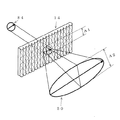
図16は従来のレンチキュラーレンズ82の光の拡散状態を示した図である。
図16において、光源84の出射光がレンチキュラーレンズ82に照射されると、レンチキュラーレンズ82を透過した光は像86に示すように、レンチキュラーレンズ82を構成する単位レンズに直交する方向には拡散されるが、平行な方向にはほとんど拡散されない。すなわちレンチキュラーレンズ82に照射された光源84の像の単位レンズに平行な方向の幅A1は透過した光の像86においてもA3となり、A1から大きくは拡大されない。
その結果光源の像が見えてしまい、光源像を見えなくするためにはレンチキュラーレンズシートを2枚用い、該シートを構成する単位レンズが直交するように該2枚のレンチキュラーレンズシートを配置する必要があった。
FIG. 16 is a diagram showing a light diffusion state of the conventional
In FIG. 16, when the light emitted from the
As a result, the image of the light source becomes visible, and in order to make the light source image invisible, it is necessary to use two lenticular lens sheets and to arrange the two lenticular lens sheets so that the unit lenses constituting the sheet are orthogonal to each other. was there.
以上のことをまとめると、従来のレンチキュラーレンズは以下のようであった。
1−カマボコ状のレンズが一方向に並びシート状に形成されている
2−単位レンズ同士が平行に並んでいる
3−光を拡散する作用がある
4−一枚のレンチキュラーレンズではレンズ曲面が存在する面のみに拡散作用があり、拡散させたい方向が一次元内にない場合、すなわち表示装置の照明装置に用いる場合、レンズシートが2枚必要
(すなわちレンチキュラーレンズでは曲率の存在する軸が1軸であったため、光を曲げる方向も1軸であった)
その結果、LED光源を使用したバックライトなどにおいてはレンチキュラーレンズ1枚のみを使用した場合拡散方向が極端に異方性拡散になってしまうという問題があった。
In summary, the conventional lenticular lens is as follows.
1-Kamaboko-shaped lenses are arranged in one direction and are formed in a sheet shape 2-Unit lenses are arranged in parallel 3-An effect of diffusing light 4-Lensicular lens has a curved surface When there is a diffusing action only on the surface to be diffused and the direction in which it is desired to diffuse is not within one dimension, that is, when it is used for a lighting device of a display device, two lens sheets are required (that is, a lenticular lens has one axis with curvature) Therefore, the light bending direction was also uniaxial)
As a result, a backlight using an LED light source has a problem that the diffusion direction becomes extremely anisotropic diffusion when only one lenticular lens is used.
このような問題はレンチキュラーレンズを構成する単位レンズ面頂点の軌跡が直線であることに起因すると考えられる。上記した特許文献1,2,3の提案においては該軌跡がすべて直線とされている。
Such a problem can be attributed to the fact that the locus of the vertex of the unit lens surface constituting the lenticular lens is a straight line. In the proposals of
解決しようとする課題は従来のレンチキュラーレンズでは光の拡散方向が異方性拡散になってしまうことで、そのため拡散させたい方向が一次元内にない、すなわち例えば表示装置の照明装置の場合、レンズシートが2枚必要だったことである。
そこで本発明の目的はレンチキュラーレンズの光の拡散方向を2次元化することにより、照明装置に用いるレンチキュラーレンズの必要枚数を減少させ安価化することである。
またレンチキュラーレンズを光拡散用に用いることにより、照明装置の光利用効率を上昇させることである。
The problem to be solved is that in the conventional lenticular lens, the light diffusion direction becomes anisotropic diffusion, and therefore the direction to be diffused is not within one dimension, that is, for example, in the case of a lighting device of a display device, the lens That means two sheets were needed.
Accordingly, an object of the present invention is to reduce the required number of lenticular lenses used in the illumination device and reduce the cost by making the light diffusion direction of the lenticular lenses two-dimensional.
Moreover, it is to raise the light utilization efficiency of an illuminating device by using a lenticular lens for light diffusion.
本発明の光拡散装置は、断面が略円形もしくは略半円形の細長のレンズ単位が一方向に並んで形成されており、かつその一単位レンズ面頂点の細長のレンズ単位方向の軌跡が略正弦波であるように周期的に高低を繰り返し、前記一方向に並んだレンズが複数本形成されており、隣り合ったレンズどうしの前記略正弦波軌跡の周期が異なることを特徴とする。
In the light diffusing device of the present invention, elongated lens units having a substantially circular or substantially semicircular cross section are formed side by side in one direction, and the locus of the elongated lens unit direction at the apex of the unit lens surface is approximately sine. A plurality of lenses arranged in the same direction are periodically formed so as to be a wave, and the periods of the substantially sinusoidal trajectories of adjacent lenses are different.
また本発明の光拡散装置は、平面状のシートもしくは板の上面及び下面のそれぞれの面に、断面が略円形もしくは略半円形の細長のレンズ単位が一方向に並んで形成されており、かつその一単位レンズ面頂点の細長のレンズ単位方向の軌跡が略正弦波であるように周期的に高低を繰り返し、前記一方向に並んだレンズが複数本形成されており、隣り合ったレンズどうしの前記略正弦波軌跡の周期が異なり、前記上面に形成された細長のレンズ単位と前記下面に形成された細長のレンズ単位とはほぼ直交していることを特徴とする。
In the light diffusing device of the present invention, elongated lens units having a substantially circular or semicircular cross section are formed in one direction on each of the upper and lower surfaces of a planar sheet or plate, and The unit lens surface apex of the elongated lens unit is repeatedly raised and lowered periodically so that the locus in the lens unit direction is a substantially sine wave, and a plurality of lenses arranged in the one direction are formed. The substantially sinusoidal trajectory has a different period , and the elongated lens unit formed on the upper surface and the elongated lens unit formed on the lower surface are substantially orthogonal to each other.
また本発明の光拡散装置は、前記断面が凸状曲面レンズであることを特徴とする。 In the light diffusing device of the present invention, the cross section is a convex curved lens.
また本発明の光拡散装置は、前記断面が凹状曲面レンズであることを特徴とする。 In the light diffusing device according to the present invention, the cross section is a concave curved lens.
また本発明の照明装置は、前記光拡散装置のうちの一つを用いたことを特徴とする。 The illumination device of the present invention is characterized by using one of the light diffusion devices.
また本発明の照明装置は導光板を有しており、前記光拡散装置を該導光板の光出力側に配置したことを特徴とする。 The illumination device of the present invention has a light guide plate, and the light diffusing device is arranged on the light output side of the light guide plate.
また本発明の照明装置は導光板を有しており、前記光拡散装置は該導光板上に作り込まれていることを特徴とする The illumination device of the present invention has a light guide plate, and the light diffusion device is built on the light guide plate.
また本発明の液晶表示装置は、前記照明装置のうちの一つを用いたことを特徴とする。 The liquid crystal display device of the present invention is characterized in that one of the lighting devices is used.
また本発明の機器は、前記液晶表示装置を用いたことを特徴とする。 The apparatus of the present invention uses the liquid crystal display device.
本発明によるレンチキュラーレンズの場合、レンズ面での曲面と正弦波での曲面が存在するため、同時に2軸に光を拡散することができ、例えば表示装置の照明装置に用いる場合、1枚のレンズシートで必要な光拡散機能が満足出来るようになった。
また光の拡散量を設計によって制御出来るのでモアレ防止や光源像が見えてしまうことの防止も可能となった。
さらにはレンチキュラーレンズを拡散板として使用可能となったため、照明装置の光利用効率を上昇させることが出来た。
In the case of the lenticular lens according to the present invention, since there are a curved surface on the lens surface and a curved surface with a sine wave, light can be diffused simultaneously in two axes. For example, when used in an illumination device of a display device, one lens The light diffusion function required by the sheet can be satisfied.
In addition, since the amount of light diffusion can be controlled by design, it is possible to prevent moiré and the appearance of a light source image.
Furthermore, since the lenticular lens can be used as a diffusion plate, the light utilization efficiency of the lighting device can be increased.
光拡散装置において、断面が略円形もしくは略半円形の細長のレンズ単位が一方向に並んで形成し、かつその一単位レンズ面頂点の細長のレンズ単位方向の軌跡が略正弦波であるように周期的に高低を繰り返すものとした。
また、前記一方向に並んだレンズを複数本形成し、隣り合ったレンズどうしの前記略正弦波軌跡の、位相もしくは周期もしくは前記レンズの形状もしくは少なくとも該3要素のうちの2つ以上を異ならせた。
さらに、該光拡散装置を照明装置の導光板の光出力側に配置した、もしくは該導光板上に作り込んだ。
In the light diffusing device, an elongated lens unit having a substantially circular or semicircular cross section is formed side by side in one direction, and the locus of the elongated lens unit at the apex of the unit lens surface is a substantially sine wave. It was assumed that the height was periodically repeated.
Further, a plurality of lenses arranged in one direction are formed, and the phase or period, the shape of the lens, or at least two of the three elements of the substantially sinusoidal trajectories of adjacent lenses are made different. It was.
Further, the light diffusing device is arranged on the light output side of the light guide plate of the lighting device or is formed on the light guide plate.
以下図1〜15を用いて本発明の実施例を説明する。
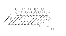
図1は光拡散装置として用いるレンチキュラーレンズをシート状にしたもの50を示した図である。
図1において、レンチキュラーレンズシート50は線状のレンズ単位ユニットR1〜R10がほぼ平行に、すなわち図示したY方向に並んで形成されている。
Embodiments of the present invention will be described below with reference to FIGS.
FIG. 1 is a view showing a
In FIG. 1, a
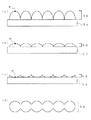
図2は図1の本発明による光拡散装置であるレンチキュラーレンズのA−A断面を示した断面図である。
図2において、レンチキュラーレンズのレンズ部は基材54上に形成されており、図2(a)においては半円形の凸状曲面レンズ、図2(b)においては半円形の凹状曲面レンズとなっている。
凸状のレンズを用いた場合も、凹状のレンズを用いた場合もそれぞれ利点がある。
基材54とレンチキュラーレンズ部52,55とは同じ材料で一度に型により成形することが望ましい。材料として例えばポリカーボネイトを使用し得る。
本発明の光拡散装置はこのようにレンチキュラーレンズにより光を拡散している。
FIG. 2 is a cross-sectional view showing the AA cross section of the lenticular lens which is the light diffusion device according to the present invention of FIG.
In FIG. 2, the lens portion of the lenticular lens is formed on a base material 54. In FIG. 2A, a semicircular convex curved lens is formed, and in FIG. 2B, a semicircular concave curved lens is formed. ing.
There are advantages both when a convex lens is used and when a concave lens is used.
The base material 54 and the lenticular lens portions 52 and 55 are preferably formed of the same material by a mold at a time. For example, polycarbonate can be used as the material.
Thus, the light diffusing device of the present invention diffuses light by the lenticular lens.
図3は本発明による光拡散装置であるレンチキュラーレンズ断面の種々の変形例を示した断面図である。
図3(a)に示したレンチキュラーレンズ部58は図2(a)に示した半円形の凸状曲面レンズ52を上方に引き延ばした形状、図3(b)に示したレンチキュラーレンズ部60は図2(a)に示した半円形の凸状曲面レンズ52を下方に押しつぶした形状、図3(c)に示したレンチキュラーレンズ部62は図2(b)に示した半円形の凹状曲面レンズ52を下方に押しつぶした形状、図3(d)に示したレンチキュラーレンズ部64は断面が円形の例である。
いずれの場合も断面が略円形もしくは略半円形のレンズが一方向に並んで形成されている。
その他、曲面レンズの曲率を変えてレンズ形状を変えることも出来る。
このように本発明の光拡散装置のレンチキュラーレンズ部断面形状は種々の変形が可能である。
光拡散装置の光拡散方向及び拡散量はこのレンチキュラーレンズ部断面形状によって多くが決定される。
FIG. 3 is a cross-sectional view showing various modifications of the cross section of the lenticular lens which is the light diffusion device according to the present invention.
The lenticular lens portion 58 shown in FIG. 3A is a shape obtained by extending the semicircular convex curved lens 52 shown in FIG. 2A upward, and the lenticular lens portion 60 shown in FIG. The semicircular convex curved lens 52 shown in FIG. 2A is crushed downward, and the lenticular lens portion 62 shown in FIG. 3C is a semicircular concave curved lens 52 shown in FIG. The lenticular lens portion 64 shown in FIG. 3D is an example having a circular cross section.
In either case, lenses having a substantially circular or substantially semicircular cross section are formed side by side in one direction.
In addition, the lens shape can be changed by changing the curvature of the curved lens.
Thus, the lenticular lens section cross-sectional shape of the light diffusing device of the present invention can be variously modified.
Many of the light diffusion direction and the diffusion amount of the light diffusion device are determined by the sectional shape of the lenticular lens portion.
本発明による光拡散装置を構成するレンチキュラーレンズの断面形状はこのように種々の形状を取り得るが、特徴とするのは単位レンズ面の頂点の軌跡である。
図2、3でPで示したのが単位レンズ面の頂点であるが、この頂点Pの軌跡、すなわち図1に示したY方向の軌跡が従来は直線であった。
しかし本発明による光拡散装置であるレンチキュラーレンズの細長の単位レンズ面頂点Pの細長のレンズ単位方向の軌跡は略正弦波であるように、周期的に高低を繰り返している。
また一方向に並んだレンズ単位が複数本形成されており、隣り合ったレンズどうしの前記略正弦波軌跡の位相もしくは周期もしくはその双方が異なるよう設定されている。
The cross-sectional shape of the lenticular lens constituting the light diffusing device according to the present invention can take various shapes as described above, but the feature is the locus of the vertex of the unit lens surface.
2 and 3 indicate the vertex of the unit lens surface. The locus of this vertex P, that is, the locus in the Y direction shown in FIG.
However, the locus of the elongated unit lens surface apex P of the lenticular lens, which is a light diffusing device according to the present invention, in the elongated lens unit direction is periodically raised and lowered so as to be a substantially sine wave.
Further, a plurality of lens units arranged in one direction are formed, and the phases and / or periods of the substantially sinusoidal trajectories of adjacent lenses are set to be different.
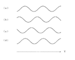
図4は前記頂点Pの軌跡の第1の実施例を示した図である。
図4において、頂点Pの軌跡は図1に示したのと同じY方向に略正弦波を描いている。
例えば図4(a)はN本目の単位レンズ頂点の軌跡、図4(b)はN+1本目の単位レンズ頂点の軌跡、図4(c)はN+2本目の単位レンズ頂点の軌跡でそれぞれピッチが同じ正弦波で位相が120度ずつ異なっている。図4(d)はN+3本目の単位レンズ頂点の軌跡でN本目と同じ位相になっている。
FIG. 4 is a diagram showing a first example of the locus of the vertex P. In FIG.
In FIG. 4, the locus of the vertex P draws a substantially sine wave in the same Y direction as shown in FIG.
For example, FIG. 4A shows the trajectory of the Nth unit lens vertex, FIG. 4B shows the trajectory of the N + 1th unit lens vertex, and FIG. 4C shows the trajectory of the N + 2th unit lens vertex. A sine wave has a phase difference of 120 degrees. FIG. 4D shows the locus of the vertex of the N + th unit lens and has the same phase as the Nth lens.
このように、隣り合ったレンズどうしの略正弦波軌跡の位相を異ならせており、3本のレンズがひと組となって同様の位相関係が繰り返されるように構成されている。
隣り合ったレンズどうしの略正弦波軌跡の位相関係をより複雑にすれば、前記ひと組となるレンズの本数をより増大させることは勿論可能で、該ひと組となる本数は多いほどよい。
レンズ単位での稜線方向の光の拡散量は略正弦波の位相によって拡散の光学的特性が決まるので、該個々のレンズの周期の設定により光学特性を設定可能である。
以下本発明の頂点が略正弦波軌跡を描くレンチキュラーレンズを正弦波レンチキュラーレンズと呼ぶ。
As described above, the phases of the substantially sinusoidal trajectories of the adjacent lenses are made different, and the same phase relationship is repeated as a group of three lenses.
If the phase relationship of the approximate sine wave trajectories between adjacent lenses is made more complex, it is of course possible to increase the number of lenses as a set, and it is better that the number of sets as a set is larger.
Since the optical diffusion characteristics are determined by the phase of the substantially sinusoidal wave, the optical characteristics can be set by setting the period of each individual lens.
Hereinafter, a lenticular lens in which the apex of the present invention draws a substantially sine wave locus is referred to as a sine wave lenticular lens.
図5は前記頂点Pの軌跡の第2の実施例を示した図である。
図5において、頂点Pの軌跡は図1に示したのと同じY方向に、図4の場合と同様、略正弦波を描いている。
図5の例が図4の例と異なるのは隣り合ったレンズどうしの描く略正弦波軌跡の異なる点である。図4の例では位相が異なっていたが、図5の例ではピッチすなわち周期が異なっている。
例えば図5(a)はN本目の単位レンズ頂点の軌跡で周期(ピッチ)T1の略正弦波、図5(b)はN+1本目の単位レンズ頂点の軌跡で周期(ピッチ)T2の略正弦波、図5(c)はN+2本目の単位レンズ頂点の軌跡で周期(ピッチ)T3の略正弦波、図5(d)はN+3本目の単位レンズ頂点の軌跡で周期(ピッチ)T2の略正弦波というように略正弦波の周期がそれぞれ異なっている。図5(e)はN+4本目の単位レンズ頂点の軌跡で、周期(ピッチ)T1の略正弦波とN本目と同様になっている。
FIG. 5 is a view showing a second embodiment of the locus of the vertex P. In FIG.
In FIG. 5, the locus of the vertex P draws a substantially sine wave in the same Y direction as shown in FIG. 1, as in FIG.
The example in FIG. 5 differs from the example in FIG. 4 in that the substantially sinusoidal locus drawn by adjacent lenses is different. In the example of FIG. 4, the phase is different, but in the example of FIG. 5, the pitch, that is, the period is different.
For example, FIG. 5A shows the locus of the Nth unit lens apex and a substantially sine wave with a period (pitch) T1, and FIG. 5B shows the locus of the N + 1th unit lens apex and a substantially sine wave with a cycle (pitch) T2. FIG. 5C is a locus of the vertex of the N + 2th unit lens and a substantially sine wave having a period (pitch) T3, and FIG. 5D is a locus of the vertex of the N + 3th unit lens and a substantially sine wave having a cycle (pitch) T2. Thus, the periods of the substantially sine waves are different. FIG. 5E shows the locus of the vertex of the (N + 4) th unit lens, which is the same as that of the Nth lens and a substantially sine wave having a period (pitch) T1.
このように、隣り合ったレンズどうしの略正弦波軌跡の周期を異ならせており、4本のレンズがひと組となって同様の周期関係が繰り返されるように構成されている。
隣り合ったレンズどうしの略正弦波軌跡の周期関係をより複雑にすれば、前記ひと組となるレンズの本数をより増大させることは勿論可能で、該ひと組となる本数は多いほどよい。
レンズ単位での稜線方向の光の拡散量は略正弦波のピッチでも拡散の大きさが決まるので、該個々のレンズの周期の設定により光拡散量を設定可能である。
As described above, the periods of the approximate sine wave trajectories of the adjacent lenses are made different, and the same periodic relation is repeated as a group of four lenses.
If the periodic relationship of the approximate sine wave trajectories between adjacent lenses is made more complex, it is of course possible to increase the number of lenses as a set, and the more the number of sets as a set, the better.
Since the diffusion amount of the light in the ridge line direction in the lens unit is determined even by a substantially sinusoidal pitch, the light diffusion amount can be set by setting the period of each individual lens.
また、図4に示したような隣り合ったレンズどうしの略正弦波軌跡の位相を異ならせる手段と、図5に示したような隣り合ったレンズどうしの略正弦波軌跡の周期を異ならせる手段とを組み合わせて用いることも効果がある。このように組み合わせると光の拡散がよりランダムな状態に近づく。
さらに、図2,3に示したような種々のレンズの形状を用い、上記に加えレンズ形状も異ならせると光の拡散状態はさらにランダムな状態に近づく。
この中でレンズ形状として凸レンズと凹レンズを組み合わせて用いることも勿論含まれ、このような手法も光の拡散をランダムな状態に近づけることに効果がある。
また略正弦波の振幅を変えたり、曲面レンズの曲率を変えることによって拡散性能変化をもたらすことも効果がある。この略正弦波の振幅を、段落番号0017で述べた要素に加えることは勿論効果的である。
Further, the means for making the phases of the substantially sinusoidal trajectories of the adjacent lenses as shown in FIG. 4 and the means for making the periods of the approximate sinusoidal trajectories of the adjacent lenses as shown in FIG. 5 different. It is also effective to use in combination. When combined in this way, light diffusion approaches a more random state.
Further, when various lens shapes as shown in FIGS. 2 and 3 are used and the lens shape is varied in addition to the above, the light diffusion state further approaches a random state.
Of these, the use of a combination of a convex lens and a concave lens as a lens shape is naturally included, and such a method is also effective in bringing light diffusion closer to a random state.
It is also effective to change the diffusion performance by changing the amplitude of the substantially sine wave or changing the curvature of the curved lens. It is of course effective to add the amplitude of the substantially sine wave to the element described in paragraph 0017.
このように単位レンズの形状を複雑化させると、単位レンズの集積によって形成される
光拡散装置の設計に多くの時間を必要とすることになるが、型が出来れば製造コストは変わらず、さらにより光の拡散がランダムに近づいているため小さな欠陥が目立たなくなって製造上の良品率を上げることが出来、その結果光拡散装置の安価化が計れるという効果がある。
If the shape of the unit lens is complicated as described above, it takes a lot of time to design the light diffusing device formed by integrating the unit lenses. Since light diffusion is approaching at random, small defects are not noticeable, and the yield of non-defective products can be increased. As a result, the light diffusing device can be reduced in cost.
図9は前記レンズ頂点Pの軌跡のピッチ(周期)を変える場合の軌跡の実例を示した図である。
図9において、Z軸は光が光拡散装置から出射されていく方向を示しており、これは光拡散装置の面に直交する方向であり、かつ照明装置に用いられる場合は被照明物が存在する方向である。(a)はピッチが0.5mm、(b)は1.0mm、(c)は2.0mm、(d)は3.0mm、(e)は5.0mmの例で、それぞれの軌跡は
Z=0.005*sin(2πY/ピッチ)
の式で表される。
FIG. 9 is a diagram showing an example of the locus when the pitch (cycle) of the locus of the lens apex P is changed.
In FIG. 9, the Z-axis indicates the direction in which light is emitted from the light diffusing device, which is a direction orthogonal to the surface of the light diffusing device, and there is an object to be illuminated when used in a lighting device. Direction. (A) is an example in which the pitch is 0.5 mm, (b) is 1.0 mm, (c) is 2.0 mm, (d) is 3.0 mm, and (e) is 5.0 mm. = 0.005 * sin (2πY / pitch)
It is expressed by the following formula.
ここで本発明の正弦波レンチキュラーレンズの光拡散作用はレンズ頂点Pが描く正弦波の振幅Aと周期Tの比率T/Aにより大きく変わる。
ここで振幅Aは図9におけるA0x2であり、周期Tは図9におけるピッチLの逆数に比例した値である。
T/Aが小さいと光の拡散作用は大きく、T/Aが大きいと光の拡散作用は小さい。T/Aの値は1〜200とするのが好ましかった。
例えば図10に示したように光源のフィラメント像を消すためには大きな光拡散が必要なため、T/Aは1〜10とするのが好ましく、光拡散作用を微少にする場合はT/Aを100〜200とするのが好ましく、サイドに光源を置くタイプの導光板にはT/Aを10〜80とするのが好ましかった。
このように本発明の正弦波レンチキュラーレンズを用いた照明装置の要求される仕様によってT/Aの値を選択するのが好ましく、その値はいろいろな用途を通して1から200の間の値とするのが好ましい。
Here, the light diffusing action of the sine wave lenticular lens of the present invention varies greatly depending on the ratio T / A of the amplitude A and the period T of the sine wave drawn by the lens apex P.
Here, the amplitude A is A0x2 in FIG. 9, and the period T is a value proportional to the reciprocal of the pitch L in FIG.
When T / A is small, the light diffusing action is large, and when T / A is large, the light diffusing action is small. The value of T / A was preferably 1 to 200.
For example, as shown in FIG. 10, in order to erase the filament image of the light source, a large light diffusion is necessary. Therefore, T / A is preferably 1 to 10, and T / A is used when the light diffusion action is to be made small. Is preferably 100 to 200, and T / A is preferably 10 to 80 for a type of light guide plate in which a light source is placed on the side.
Thus, it is preferable to select the value of T / A according to the required specification of the lighting device using the sine wave lenticular lens of the present invention, and the value is set to a value between 1 and 200 through various applications. Is preferred.
次に本発明で光拡散装置に用いる正弦波レンチキュラーレンズの実例を図6、7,8を用いて説明する。
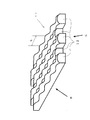
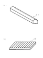
図6は本発明による光拡散装置を構成する正弦波レンチキュラーレンズの単位レンズの例である。
図6において、単位レンズ12は図2,3で示した基材54と一体化されて同じ素材で形成されており、断面は基材上に曲面のレンズ部が乗った食パン状の形状をしている。なお図6は凸状レンズの例を示している。
図6におけるレンズ頂点の軌跡は略正弦波状となって周期的に高低を繰り返している。
なおLはレンズ頂点のピッチ(周期)を示している。
Next, an example of a sine wave lenticular lens used in the light diffusing device according to the present invention will be described with reference to FIGS.
FIG. 6 shows an example of a unit lens of a sine wave lenticular lens constituting the light diffusion device according to the present invention.
In FIG. 6, the unit lens 12 is integrated with the base material 54 shown in FIGS. 2 and 3 and is formed of the same material, and the cross section has a bread-like shape with a curved lens portion on the base material. ing. FIG. 6 shows an example of a convex lens.
The locus of the lens apex in FIG. 6 has a substantially sinusoidal shape and periodically repeats high and low.
Note that L indicates the pitch (cycle) of the lens apex.
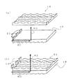
図7は図6に示した一方向に並んだ単位レンズ12を複数本集積してシート上の正弦波レンチキュラーレンズ14とした例で、この例では図4に示したように隣り合ったレンズどうしのレンズ頂点の略正弦波軌跡の位相が異なるよう設定されている。
なお図7においてはシートの片面に正弦波レンチキュラーレンズが設けられている図を示したが、正弦波レンチキュラーレンズをシートの両面に設けても大きな効果がある。
FIG. 7 shows an example in which a plurality of unit lenses 12 arranged in one direction shown in FIG. 6 are integrated to form a sine wave lenticular lens 14 on a sheet. In this example, adjacent lenses as shown in FIG. The phase of the approximate sine wave locus of the lens apex is set to be different.
Although FIG. 7 shows a diagram in which a sine wave lenticular lens is provided on one side of the sheet, a great effect can be obtained by providing sine wave lenticular lenses on both sides of the sheet.
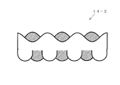
図8は図7に示した正弦波レンチキュラーレンズ14の側面を示した図で、図8(a)が図7に示したB方向から見た図、図8(b)が図7に示したC方向から見た図である。 8 is a view showing a side surface of the sine wave lenticular lens 14 shown in FIG. 7. FIG. 8 (a) is a view seen from the direction B shown in FIG. 7, and FIG. 8 (b) is shown in FIG. It is the figure seen from C direction.
図10は本発明の光拡散装置の光の拡散状態を示した図で、従来の光拡散装置を示した図16と比較している。
図10において、光源84の出射光が正弦波レンチキュラーレンズ14に照射されると、正弦波レンチキュラーレンズ14を透過した光は像50に示すように、正弦波レンチキュラーレンズ14を構成する単位レンズに直交する方向及び平行な方向にも拡散される。すなわち正弦波レンチキュラーレンズ14に照射された光源84の像の単位レンズに平行な方向の幅A1は透過した光の像50においてはA2となり、A1から拡大される。これが平行な方向にはほとんど拡大されなかった従来のレンチキュラーレンズに対する本発明の正弦波レンチキュラーレンズの効果である。
この結果光源の像が見えてしまうことがなくなり、正弦波レンチキュラーレンズ1枚で光源像を見えなくすることが可能になった。
FIG. 10 is a diagram showing a light diffusion state of the light diffusing device of the present invention, and is compared with FIG. 16 showing a conventional light diffusing device.
In FIG. 10, when light emitted from the
As a result, the image of the light source is not seen and the light source image can be made invisible with one sine wave lenticular lens.
従来はフィラメントのような光源で照射した場合、光源の形が照射面に写り問題になることがあったため、レンチキュラーのようなシートを入れることで、光源像を拡散させ消していた。この光源の場合、フィラメント長さ方向は線状となっており、弱い拡散でもよく、フィラメント巻き軸方向は点状で大きな拡散が必要であった。
従来のレンチキュラーレンズは1軸拡散であるため、巻き軸方向に拡散させる作用のレンズを用いていたが、本発明の正弦波レンチキュラーレンズは単位レンズの長さ方向(拡散度が低くても良い)にも拡散作用があるため、光源の像を1枚のレンズで対策することが可能となった。
またこのように光を2軸に拡散するため、モアレ防止にも大きな効果があった。
Conventionally, when illuminating with a light source such as a filament, the shape of the light source is sometimes reflected on the irradiated surface, so that a light source image is diffused and erased by inserting a sheet such as a lenticular. In the case of this light source, the filament length direction is linear, which may be weak diffusion, and the filament winding axis direction is point-like and requires large diffusion.
Since the conventional lenticular lens has uniaxial diffusion, a lens that diffuses in the winding axis direction is used. However, the sine wave lenticular lens of the present invention has a unit lens length direction (the diffusivity may be low). Since there is also a diffusing action, it is possible to take measures against the image of the light source with a single lens.
In addition, since the light is diffused biaxially in this way, there is a great effect in preventing moire.
図11は本発明による正弦波レンチキュラーレンズを用いてサイドライト型照明装置を構成した例である。なお照明装置においては例えばプリズムシートのような各種の光学特性を持ったシート類を追加使用することが一般的であるが、ここでは単純化のため省略している。
図11(a)において、LED光源20は導光板18のサイドに配置され、導光板18の下面にはプリズムが形成され、導光板18の光出射側である上面には本発明による凸状のレンズを用いた正弦波レンチキュラーレンズ14がシート状に形成されて配置されている。
FIG. 11 shows an example in which a sidelight type illumination device is configured using a sine wave lenticular lens according to the present invention. In addition, in an illuminating device, for example, sheets having various optical characteristics such as a prism sheet are generally additionally used, but are omitted here for simplification.
In FIG. 11A, the
LED光源20の光は当初H1方向に進行し、導光板18下面のプリズムで方向を上方であるH2方向に変えられ出射する。正弦波レンチキュラーレンズの線状の単位レンズは当初の光進行方向H1と平行に置かれる。
このように照明装置を構成すると、正弦波レンチキュラーレンズ1枚で、光利用効率を落とすことなく、LED光源20の像を拡散させることが出来るという効果があり、均一化した照明光を前記各種のシート類を介して表示装置に送ることが出来る。
すなわち本発明の正弦波レンチキュラーレンズは、従来の拡散板を置き換えて光の高効率化を計ることが出来、このような置き換えはプリズムシートを1枚使うタイプの照明装置にも、2枚使うタイプにも有効である。
The light from the LED
When the illumination device is configured in this way, there is an effect that the image of the
That is, the sine wave lenticular lens of the present invention can improve the efficiency of light by replacing a conventional diffuser, and such a replacement is also a type that uses two prisms for an illumination device that uses one prism sheet. Also effective.
図11(b)においては本発明による正弦波レンチキュラーレンズが導光板22に作り込まれている。すなわち導光板22の下面にはプリズムが、光出力側である上面には正弦波レンチキュラーレンズが作り込まれており、正弦波レンチキュラーレンズが作り込まれたことにより導光板の光制御に関する性能が高性能化されている。これらが同一基材で形成されているのは勿論で、例えば基材としてポリカーボネイトを使い得る。
このように導光板に正弦波レンチキュラーレンズを作り込めば安価化及び薄型化に効果がある。
In FIG. 11B, the sine wave lenticular lens according to the present invention is built in the
In this way, if a sine wave lenticular lens is formed on the light guide plate, it is effective in reducing the cost and thickness.
なお正弦波レンチキュラーレンズを、図17に示すように、凹状のレンズを用いた正弦波レンチキュラーレンズ15をシート状に形成して配置したり(図17a)、導光板22に作り込む構成(図17b)も当然あり得る。 In addition, as shown in FIG. 17, the sine wave lenticular lens is formed by arranging the sine wave lenticular lens 15 using a concave lens in the form of a sheet (FIG. 17a) or built in the light guide plate 22 (FIG. 17b). ) Is also possible.
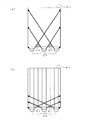
図12は本発明による正弦波レンチキュラーレンズの1つの効果を説明する図で、照明装置の平面図を示している。
図12(a)は従来のレンチキュラーレンズを用いた場合を示した照明装置の平面図で、導光板82のサイドにLED光源20が配置され、導光板82上にはレンチキュラーレンズが配置されていない。
このような場合は、LED光源20の出射光が太線で示したような軌跡をとるため、LED光源20の間に暗い場所90が生じてしまうという問題があった。
FIG. 12 is a diagram for explaining one effect of the sine wave lenticular lens according to the present invention, and shows a plan view of the illumination device.
FIG. 12A is a plan view of a lighting device showing a case where a conventional lenticular lens is used. The
In such a case, the emitted light of the
図12(b)ではレンチキュラーレンズを用いた場合を示した照明装置の平面図で、導光板のサイドにLED光源20が配置され、導光板82上にはレンチキュラーレンズが配置されて、レンチキュラーレンズと導光板とが83とされている。
導光板83上の実線はレンチキュラーレンズを構成する単位レンズの方向、すなわち単位レンズの頂点の稜線方向を示しており、図示のように線状の単位レンズが当初の光進行方向H1と平行に置かれると、レンチキュラーレンズの線状の単位レンズと直行する方向には光の拡散が大きい。そのため、図示のように、太線で示したLED光源20の出射光は図12(a)の場合よりも拡散された軌跡をとり、前記暗い場所91を小さくすることが出来る。
FIG. 12B is a plan view of the lighting device showing a case where a lenticular lens is used, in which the
The solid line on the light guide plate 83 indicates the direction of the unit lens constituting the lenticular lens, that is, the ridge line direction of the apex of the unit lens. As shown in the figure, the linear unit lens is placed in parallel with the initial light traveling direction H1. As a result, the diffusion of light is large in the direction perpendicular to the linear unit lens of the lenticular lens. Therefore, as shown in the figure, the emitted light of the
ところがレンチキュラーレンズに従来のもの、例えばレンチキュラーレンズを構成する単位レンズ面頂点の軌跡が直線であるもの、を用いると、液晶表示装置越しでぎらつき感がでたり見栄えが悪かいという問題が出てしまいLED入光部側の見栄えが改善しきれないという別の問題が生じてしまう。暗所の解消を含め、このような問題は拡散シートを用いて光拡散量を調整すれば生じなかった問題だが、従来の拡散シートで調整すると照明装置の光利用効率が低下してしまうという問題があった。 However, when a conventional lenticular lens is used, for example, the unit lens surface vertex constituting the lenticular lens is a straight line, there is a problem that the liquid crystal display device has a glare or poor appearance. In other words, another problem arises that the appearance on the LED light incident part side cannot be improved. This problem, including the elimination of dark places, was not caused by adjusting the amount of light diffusion using a diffusion sheet, but the light utilization efficiency of the lighting device would be reduced if adjustment was made using a conventional diffusion sheet was there.
しかし図12(b)でレンチキュラーレンズとして本発明の正弦波レンチキュラーを用いると、線状の単位レンズと直行する方向、すなわちLED配列軸方向には大きい拡散作用を持っており、さらに線状の単位レンズと平行な方向にも小さい拡散作用を持っているため、輝度を低下させずに見栄えやギラツキ感を低減させる事ができる。 However, when the sine wave lenticular of the present invention is used as the lenticular lens in FIG. 12B, it has a large diffusing action in the direction perpendicular to the linear unit lens, that is, the LED array axis direction. Since it has a small diffusing action in the direction parallel to the lens, it can reduce the appearance and glare without reducing the luminance.
図18は本発明の第3の実施例の光拡散装置の側面を示した図である。
図18は図8(a),(b)に対応した図で、図18に示した光拡散装置14−2は、平面状のシートもしくは板の上面及び下面のそれぞれの面に、断面が略円形もしくは略半円形の細長のレンズ単位が一方向に並んで形成されており、かつその一単位レンズ面頂点の細長のレンズ単位方向の軌跡が略正弦波であるように周期的に高低を繰り返し、前記上面に形成された細長のレンズ単位と前記下面に形成された細長のレンズ単位とはほぼ直交している。
このようにシートもしくは板の上面及び下面のそれぞれの面に正弦波レンチキュラーレンズを設けかつ上面と下面とで細長のレンズ単位をほぼ直交させると、より光の拡散を均一化させることが出来る。
FIG. 18 is a view showing a side surface of the light diffusion device according to the third embodiment of the present invention.
FIG. 18 is a diagram corresponding to FIGS. 8A and 8B, and the light diffusing device 14-2 shown in FIG. 18 has a substantially cross section on each of the upper and lower surfaces of a planar sheet or plate. Circularly or semi-circular elongated lens units are formed side by side in one direction, and the trajectory of the elongated lens unit direction at the apex of the unit lens surface is periodically sine wave repeated periodically. The elongated lens unit formed on the upper surface and the elongated lens unit formed on the lower surface are substantially orthogonal to each other.
In this manner, when sine wave lenticular lenses are provided on the upper and lower surfaces of the sheet or plate and the elongated lens units are substantially orthogonal to each other on the upper and lower surfaces, the light diffusion can be made more uniform.
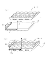
図19は本発明の第3の実施例の正弦波レンチキュラーレンズを用いてサイドライト型照明装置を構成した例で、図11に対応した変形例である。
図19(a)の14−2は図18に側面図を示した本発明の第3の実施例の光拡散装置の斜視図である。
原則的には光拡散装置14−2は、上面に設けられた正弦波レンチキュラーレンズの線状の単位レンズが当初の光進行方向H1と平行になるよう導光板18上に置かれる。しかし図19のように上下両面に正弦波レンチキュラーレンズを設けた場合は、「より光の拡散を均一化させることが出来る」という効果に加え、図11に示したタイプの場合よりも組立時の角度設定の余裕度が大きい、又特殊な用途の場合は光進行方向H1に対して回転させて用いることもできるという効果もある。
その他図11と同様の効果を有することは勿論である。
FIG. 19 shows an example in which a sidelight type illumination device is configured using the sine wave lenticular lens of the third embodiment of the present invention, which is a modification corresponding to FIG.
Reference numeral 14-2 in FIG. 19A is a perspective view of the light diffusing device according to the third embodiment of the present invention whose side view is shown in FIG.
In principle, the light diffusing device 14-2 is placed on the
Of course, other effects similar to those of FIG. 11 are obtained.
図19(b)においては本発明による正弦波レンチキュラーレンズが導光板22の両面に作り込まれている。すなわち導光板22−2の下面と上面にそれぞれ正弦波レンチキュラーレンズが作り込まれており、それぞれの面に作り込まれた細長のレンズ単位は互いにほぼ直交している。
正弦波レンチキュラーレンズが両面に作り込まれたことにより導光板の光制御に関する性能、特に光拡散性能が高性能化されている。これらが同一基材で形成されているのは勿論で、例えば基材としてポリカーボネイトを使い得る。
このように導光板に正弦波レンチキュラーレンズを作り込めば安価化及び薄型化に効果がある。
In FIG. 19B, sine wave lenticular lenses according to the present invention are formed on both surfaces of the
Since the sine wave lenticular lens is formed on both sides, the performance relating to the light control of the light guide plate, particularly the light diffusion performance is improved. Of course, they are formed of the same base material, and for example, polycarbonate can be used as the base material.
In this way, if a sine wave lenticular lens is formed on the light guide plate, it is effective in reducing the cost and thickness.
このような本発明の正弦波レンチキュラーレンズを配置する場所を検討してみる。
図13は液晶装置28及びそれを照明するバックライト装置23の一般的な断面図であるが、図13(a),(b)に示した拡散板30をシート状にした本発明の正弦波レンチキュラーレンズに置き換えることは勿論可能である。
このように置き換えれば、すなわち照明光を均一化した後プリズムシート29,38,40に照明光を入射させれば、照明装置の光利用効率を向上させることが出来る。
また本発明の正弦波レンチキュラーレンズを図13(a),(b)に示した導光板22上に作り込むことも可能である。その場合拡散板30を省くことが出来、上記の効果に加え安価化、薄型化が可能という効果が加わる。
勿論主たる光の拡散作用をレンチキュラーレンズによって行い、さらに光学特性の向上のため拡散板を用いることも有効な選択である。
Consider a place where such a sine wave lenticular lens of the present invention is placed.
FIG. 13 is a general cross-sectional view of the liquid crystal device 28 and the
If replaced in this way, that is, if the illumination light is made incident on the prism sheets 29, 38 and 40 after the illumination light is made uniform, the light utilization efficiency of the illumination device can be improved.
Further, the sine wave lenticular lens of the present invention can be formed on the
Of course, it is also an effective choice to perform the main light diffusing action with a lenticular lens and to use a diffusing plate to further improve the optical characteristics.
さらに本発明の正弦波レンチキュラーレンズの光学特性の選択によっては図13(b)における2枚のプリズムシート38,40を1枚にしたり、場合によっては図13におけるプリズムシート29,38,40を置き換えてしまうことも考えられる。
このようにした場合は大きな安価化効果が生じる。
このように本発明の正弦波レンチキュラーレンズを照明装置に用いた液晶表示装置は安価でかつ光利用効率が高いという効果を有する。
Further, depending on the selection of the optical characteristics of the sine wave lenticular lens of the present invention, the two prism sheets 38 and 40 in FIG. 13B are made one, or in some cases, the prism sheets 29, 38 and 40 in FIG. 13 are replaced. It is also possible that
In such a case, a great cost reduction effect occurs.
As described above, the liquid crystal display device using the sine wave lenticular lens of the present invention for an illumination device has an effect of being inexpensive and having high light utilization efficiency.
図14は本発明の照明装置76を用いた液晶表示装置74を有する機器70の例で、携帯電話機を示している。
本発明による液晶表示装置を用いた機器は安価でかつ光利用効率の高いものとすることが出来る。
また本発明による液晶表示装置は、携帯電話機のような小型機器のみではなく、テレビのような比較的大型の機器に用いても効果があることは勿論である。
FIG. 14 shows an example of a device 70 having a liquid crystal display device 74 using the lighting device 76 of the present invention, and shows a mobile phone.
An apparatus using the liquid crystal display device according to the present invention can be inexpensive and have high light utilization efficiency.
Of course, the liquid crystal display device according to the present invention is effective not only for small devices such as mobile phones but also for relatively large devices such as televisions.
以上から本発明の正弦波レンチキュラーレンズの特徴をまとめてみると、
1−従来のレンチキュラーレンズの場合、1軸のみの光拡散であったのに対し、正弦波レンチキュラーレンズにすることにより1種類の部材で2軸の光拡散度を変えることができる。
2−正弦波の軌跡を変更することで、光拡散量を制御できる。
3−正弦波レンチキュラーレンズ面はシート或いは厚みのある部材であっても良い。
したがってシート状にすることも出来るし、導光板に作り込むことも出来る。
4−正弦波レンチキュラーレンズはシートや導光板面の両面にあっても良い。
From the above, when summarizing the characteristics of the sine wave lenticular lens of the present invention,
1—In the case of a conventional lenticular lens, light diffusion is only uniaxial, but by using a sine wave lenticular lens, the biaxial light diffusivity can be changed with one type of member.
The amount of light diffusion can be controlled by changing the locus of the 2-sine wave.
The 3-sine wave lenticular lens surface may be a sheet or a thick member.
Therefore, it can be formed into a sheet shape or can be built into the light guide plate.
The 4-sine wave lenticular lens may be on both sides of the sheet or the light guide plate surface.
また本発明の正弦波レンチキュラーレンズは隣り合ったレンズどうしの正弦波に規則性がなければないほど良い。そのためには多くの要素を変化させることが望ましい。
さらに製造方法としては、直接加工の場合、レンズ曲率バイトを直線状に加工するのではなく、正弦波の軌跡にて加工すればよく、通常のレンチキュラーレンズ作成の方法がとれる。
さらにまたシート成形のような押し出し成形の場合、出口を上下させることでシート状の正弦波レンチキュラーレンズを作成することができる。
Further, the sine wave lenticular lens of the present invention is so good that the sine wave between adjacent lenses is not regular. To that end, it is desirable to change many factors.
Further, as a manufacturing method, in the case of direct processing, the lens curvature bite is not processed in a straight line, but may be processed in a locus of a sine wave, and a normal method of creating a lenticular lens can be taken.
Furthermore, in the case of extrusion molding such as sheet molding, a sheet-like sine wave lenticular lens can be created by moving the outlet up and down.
また本明細書では一方のサイドに光源を置くタイプの照明装置を例にとって説明したが、本発明の正弦波レンチキュラーレンズが2つのサイドに光源を置くタイプの照明装置や導光板の下に光源を置くタイプの直下型照明装置にも有用であることは勿論である。 Further, in this specification, an example of a lighting device in which a light source is placed on one side has been described. However, a light source is placed under a light guide plate or a lighting device in which the sine wave lenticular lens of the present invention places a light source on two sides. Of course, it is also useful for the direct type lighting device of the placing type.
12 単位レンズ
P 単位レンズ面頂点
14、14−2 光拡散装置
23、76 照明装置。
18,22、22−2 導光板
22、22−2 光拡散装置が作り込まれた導光板
28,74 液晶表示装置
70 機器。
12 Unit lens P Unit lens surface vertex 14, 14-2
18, 22, 22-2
Claims (9)
A device using the liquid crystal display device according to claim 8.
Priority Applications (4)
| Application Number | Priority Date | Filing Date | Title |
|---|---|---|---|
| JP2006169240A JP4874009B2 (en) | 2006-06-19 | 2006-06-19 | Light diffuser |
| DE102007027947A DE102007027947A1 (en) | 2006-06-19 | 2007-06-18 | Optical element e.g. light diffusing sheet for lighting device used for liquid crystal display (LCD) has parallel elongated lens surfaces whose height of arcuate cross-section varies continuously and repeatedly in longitudinal direction |
| US11/820,343 US20070291369A1 (en) | 2006-06-19 | 2007-06-19 | Optical element, lighting device, and liquid crystal display device |
| CNA2007101421864A CN101101343A (en) | 2006-06-19 | 2007-06-19 | Optical element, lighting device and liquid crystal display device |
Applications Claiming Priority (1)
| Application Number | Priority Date | Filing Date | Title |
|---|---|---|---|
| JP2006169240A JP4874009B2 (en) | 2006-06-19 | 2006-06-19 | Light diffuser |
Publications (3)
| Publication Number | Publication Date |
|---|---|
| JP2007334257A JP2007334257A (en) | 2007-12-27 |
| JP2007334257A5 JP2007334257A5 (en) | 2009-05-07 |
| JP4874009B2 true JP4874009B2 (en) | 2012-02-08 |
Family
ID=38777160
Family Applications (1)
| Application Number | Title | Priority Date | Filing Date |
|---|---|---|---|
| JP2006169240A Expired - Fee Related JP4874009B2 (en) | 2006-06-19 | 2006-06-19 | Light diffuser |
Country Status (4)
| Country | Link |
|---|---|
| US (1) | US20070291369A1 (en) |
| JP (1) | JP4874009B2 (en) |
| CN (1) | CN101101343A (en) |
| DE (1) | DE102007027947A1 (en) |
Families Citing this family (12)
| Publication number | Priority date | Publication date | Assignee | Title |
|---|---|---|---|---|
| KR20090086759A (en) * | 2008-02-11 | 2009-08-14 | 삼성정밀화학 주식회사 | A prism sheet having a prism acid having a longitudinal wave pattern with improved front luminance, a backlight unit employing the same, and a liquid crystal display device having the backlight unit. |
| TW201017290A (en) * | 2008-10-23 | 2010-05-01 | Coretronic Corp | Light source module |
| KR101597014B1 (en) * | 2009-02-26 | 2016-02-24 | 다이니폰 인사츠 가부시키가이샤 | Mold for forming optical sheet, and method for manufacturing mold |
| JP5610202B2 (en) * | 2010-06-23 | 2014-10-22 | ミネベア株式会社 | Surface lighting device |
| TWI417583B (en) * | 2011-03-03 | 2013-12-01 | Futis Internat Ltd | A microstructure light phase shifting film and lens |
| US8591074B1 (en) * | 2012-09-05 | 2013-11-26 | Top International Enterprise Limited | Secondary optical lens |
| JP6148495B2 (en) * | 2013-02-25 | 2017-06-14 | 恵和株式会社 | Light guide film for ultra-thin liquid crystal backlight, ultra-thin liquid crystal backlight unit, and portable computer |
| JP6203513B2 (en) * | 2013-03-28 | 2017-09-27 | 恵和株式会社 | LIGHT GUIDE FILM, BACKLIGHT UNIT, PORTABLE COMPUTER, AND LIGHT GUIDE FILM MANUFACTURING METHOD |
| DE102015202515A1 (en) * | 2015-02-12 | 2016-08-18 | Zumtobel Lighting Gmbh | Optical element for influencing the light output of lamps |
| JP7493317B2 (en) * | 2018-09-21 | 2024-05-31 | デクセリアルズ株式会社 | Light diffusion plate, image display device and lighting device |
| JP7785449B2 (en) * | 2020-12-18 | 2025-12-15 | デクセリアルズ株式会社 | Diffuser, display device, projection device, lighting device, and light source for remote sensing |
| TWI838977B (en) * | 2022-11-25 | 2024-04-11 | 達運精密工業股份有限公司 | Light guide plate structure |
Family Cites Families (32)
| Publication number | Priority date | Publication date | Assignee | Title |
|---|---|---|---|---|
| JPS63261383A (en) * | 1987-04-20 | 1988-10-28 | 日本ビクター株式会社 | Display panel |
| JPH0830848B2 (en) * | 1988-04-15 | 1996-03-27 | 株式会社日立製作所 | Multi-screen projector |
| JPH02110525A (en) * | 1988-10-20 | 1990-04-23 | Dainippon Printing Co Ltd | Lenticular lens sheet and its manufacturing method |
| US5552907A (en) * | 1992-01-27 | 1996-09-03 | Sekisui Chemical Co., Ltd. | Light adjusting sheet having a sinusoidal surface and a non-optically flat surface and useable with an LCD |
| KR0168879B1 (en) * | 1992-12-25 | 1999-04-15 | 기따지마 요시또시 | Renticular lens, surface light source and liquid crystal display apparatus |
| US5598280A (en) * | 1993-03-23 | 1997-01-28 | Dai Nippon Printing Co., Ltd. | Film lens and a surface light source using the same |
| JPH08262206A (en) * | 1995-03-23 | 1996-10-11 | Hitachi Ltd | Prism sheet |
| JP3653308B2 (en) * | 1995-08-01 | 2005-05-25 | 日東樹脂工業株式会社 | Surface light source device and liquid crystal display |
| TW331593B (en) * | 1996-05-13 | 1998-05-11 | Konika Co Ltd | Planer light source device and light guide plate |
| JPH09311203A (en) * | 1996-05-16 | 1997-12-02 | Dainippon Printing Co Ltd | Orthogonal lenticular lens sheet and manufacturing method thereof |
| US5854872A (en) * | 1996-10-08 | 1998-12-29 | Clio Technologies, Inc. | Divergent angle rotator system and method for collimating light beams |
| EP1975649A1 (en) * | 1998-02-18 | 2008-10-01 | Minnesota Mining And Manufacturing Company | Optical film |
| JP2001006422A (en) * | 1999-06-18 | 2001-01-12 | Enplas Corp | Sidelight type surface light source device and liquid crystal display device |
| US6845212B2 (en) * | 1999-10-08 | 2005-01-18 | 3M Innovative Properties Company | Optical element having programmed optical structures |
| US7046905B1 (en) * | 1999-10-08 | 2006-05-16 | 3M Innovative Properties Company | Blacklight with structured surfaces |
| JP4408166B2 (en) * | 2000-04-27 | 2010-02-03 | 大日本印刷株式会社 | Directional diffusion film and manufacturing method thereof, surface light source device and liquid crystal display device |
| CA2413700C (en) * | 2000-07-11 | 2007-01-09 | 3M Innovative Properties Company | Backlight with structured sufaces |
| US7230764B2 (en) * | 2000-08-18 | 2007-06-12 | Reflexite Corporation | Differentially-cured materials and process for forming same |
| US7320535B2 (en) * | 2002-08-30 | 2008-01-22 | Kimoto Co., Ltd. | Light control film |
| JP2004351667A (en) * | 2003-05-27 | 2004-12-16 | Hitachi Maxell Ltd | Manufacturing method of uniaxial diffusion surface and light guide plate for liquid crystal display device manufactured using the same, diffusion sheet, liquid crystal display device |
| US7106517B2 (en) * | 2003-12-31 | 2006-09-12 | General Electric Company | Display optical films |
| TWM255146U (en) * | 2004-04-22 | 2005-01-11 | Shih-Chieh Tang | Brightness enhancement film having curved prism units |
| TWI330282B (en) * | 2004-04-30 | 2010-09-11 | Chimei Innolux Corp | Light guide plate and backlight moudule using same |
| JP4449036B2 (en) * | 2004-06-03 | 2010-04-14 | ミネベア株式会社 | Surface lighting device |
| KR100487105B1 (en) * | 2004-06-04 | 2005-05-04 | 주식회사 엘지에스 | Optical film |
| JP4504141B2 (en) * | 2004-09-09 | 2010-07-14 | 大日本印刷株式会社 | Surface light source device |
| US7212345B2 (en) * | 2004-09-13 | 2007-05-01 | Eastman Kodak Company | Randomized patterns of individual optical elements |
| KR100682875B1 (en) * | 2005-06-08 | 2007-02-15 | 삼성전기주식회사 | Light guide plate with multi-cycle pattern and lighting device for display device using same |
| KR100647327B1 (en) * | 2005-06-18 | 2006-11-23 | 삼성전기주식회사 | Lighting device for flat display device, and flat display device having same |
| TWI274896B (en) * | 2005-06-30 | 2007-03-01 | Efun Technology Co Ltd | Brightness enhancement film having reinforcing layer |
| TWI391711B (en) * | 2005-09-13 | 2013-04-01 | 迎輝科技股份有限公司 | Condenser with light guiding structure |
| TWI278662B (en) * | 2006-03-31 | 2007-04-11 | Gamma Optical Co Ltd | Optical film structure |
-
2006
- 2006-06-19 JP JP2006169240A patent/JP4874009B2/en not_active Expired - Fee Related
-
2007
- 2007-06-18 DE DE102007027947A patent/DE102007027947A1/en not_active Withdrawn
- 2007-06-19 CN CNA2007101421864A patent/CN101101343A/en active Pending
- 2007-06-19 US US11/820,343 patent/US20070291369A1/en not_active Abandoned
Also Published As
| Publication number | Publication date |
|---|---|
| DE102007027947A1 (en) | 2008-01-03 |
| JP2007334257A (en) | 2007-12-27 |
| CN101101343A (en) | 2008-01-09 |
| US20070291369A1 (en) | 2007-12-20 |
Similar Documents
| Publication | Publication Date | Title |
|---|---|---|
| TWI378270B (en) | Diffuser prism sheet comprising light diffuser in the valley of prism and lcd back light unit thereby | |
| JP4980425B2 (en) | display | |
| JP4873683B2 (en) | Surface light source device | |
| JP5071675B2 (en) | Illumination device and display device | |
| TW201514548A (en) | Optical substrates having light collimating and diffusion structures | |
| JP4874009B2 (en) | Light diffuser | |
| JP2014038747A (en) | Light guide plate, surface light source device and transmission type display device | |
| US7537373B2 (en) | Light guide plate and backlight module using the same | |
| US7581850B2 (en) | Light guide plate and backlight module using the same | |
| US7997780B2 (en) | Lighting device | |
| JP2001183642A (en) | Multi-prism sheet and liquid crystal display device using the same | |
| TW200426410A (en) | Light guide plate and backlight system using the same | |
| JP2014086245A (en) | Light guide plate, backlight unit and display device | |
| EP2048433A1 (en) | Planar light emitting device, optical element and liquid crystal display device | |
| JP4641457B2 (en) | Light control sheet and surface light source device | |
| JP2012103290A (en) | Optical sheet, backlight unit and liquid crystal display device | |
| TW202305416A (en) | Backlight module having optical film with deflective microstructures | |
| JP2009026753A (en) | Illumination device and optical adjustment member used therefor | |
| CN100443987C (en) | Curved optical modulation element and backlight module with same | |
| JP2008216831A (en) | OPTICAL ADJUSTING MEMBER, LIGHTING DEVICE AND LIQUID CRYSTAL DISPLAY DEVICE, AND OPTICAL ADJUSTING MEMBER MANUFACTURING METHOD | |
| JP5700169B2 (en) | Light guide plate, surface light source device, transmissive display device | |
| JP4910946B2 (en) | Light control sheet, surface light source device, transmissive display device | |
| KR102009855B1 (en) | Light guide panel | |
| KR20130015271A (en) | Optical sheet for condensing light and back light unit comprising the same | |
| JP2012243526A (en) | Light guide plate, backlight unit, and image display device |
Legal Events
| Date | Code | Title | Description |
|---|---|---|---|
| A521 | Request for written amendment filed |
Free format text: JAPANESE INTERMEDIATE CODE: A523 Effective date: 20090325 |
|
| A621 | Written request for application examination |
Free format text: JAPANESE INTERMEDIATE CODE: A621 Effective date: 20090325 |
|
| A977 | Report on retrieval |
Free format text: JAPANESE INTERMEDIATE CODE: A971007 Effective date: 20110421 |
|
| A131 | Notification of reasons for refusal |
Free format text: JAPANESE INTERMEDIATE CODE: A131 Effective date: 20110427 |
|
| A521 | Request for written amendment filed |
Free format text: JAPANESE INTERMEDIATE CODE: A523 Effective date: 20110621 |
|
| A131 | Notification of reasons for refusal |
Free format text: JAPANESE INTERMEDIATE CODE: A131 Effective date: 20110921 |
|
| A521 | Request for written amendment filed |
Free format text: JAPANESE INTERMEDIATE CODE: A523 Effective date: 20111027 |
|
| TRDD | Decision of grant or rejection written | ||
| A01 | Written decision to grant a patent or to grant a registration (utility model) |
Free format text: JAPANESE INTERMEDIATE CODE: A01 Effective date: 20111121 |
|
| A01 | Written decision to grant a patent or to grant a registration (utility model) |
Free format text: JAPANESE INTERMEDIATE CODE: A01 |
|
| A61 | First payment of annual fees (during grant procedure) |
Free format text: JAPANESE INTERMEDIATE CODE: A61 Effective date: 20111122 |
|
| FPAY | Renewal fee payment (event date is renewal date of database) |
Free format text: PAYMENT UNTIL: 20141202 Year of fee payment: 3 |
|
| R150 | Certificate of patent or registration of utility model |
Ref document number: 4874009 Country of ref document: JP Free format text: JAPANESE INTERMEDIATE CODE: R150 Free format text: JAPANESE INTERMEDIATE CODE: R150 |
|
| R250 | Receipt of annual fees |
Free format text: JAPANESE INTERMEDIATE CODE: R250 |
|
| R250 | Receipt of annual fees |
Free format text: JAPANESE INTERMEDIATE CODE: R250 |
|
| R250 | Receipt of annual fees |
Free format text: JAPANESE INTERMEDIATE CODE: R250 |
|
| R250 | Receipt of annual fees |
Free format text: JAPANESE INTERMEDIATE CODE: R250 |
|
| LAPS | Cancellation because of no payment of annual fees |