JP4871750B2 - Sheet processing apparatus and image forming apparatus - Google Patents

Sheet processing apparatus and image forming apparatus Download PDF

Info

Publication number
JP4871750B2
JP4871750B2 JP2007021569A JP2007021569A JP4871750B2 JP 4871750 B2 JP4871750 B2 JP 4871750B2 JP 2007021569 A JP2007021569 A JP 2007021569A JP 2007021569 A JP2007021569 A JP 2007021569A JP 4871750 B2 JP4871750 B2 JP 4871750B2
Authority
JP
Japan
Prior art keywords
sheet
sheet bundle
folded
bundle
processing apparatus
Prior art date
Legal status (The legal status is an assumption and is not a legal conclusion. Google has not performed a legal analysis and makes no representation as to the accuracy of the status listed.)
Active
Application number
JP2007021569A
Other languages
Japanese (ja)
Other versions
JP2008184311A (en
JP2008184311A5 (en
Inventor
学玄 早坂
奈作 神谷
大渕  裕輔
Current Assignee (The listed assignees may be inaccurate. Google has not performed a legal analysis and makes no representation or warranty as to the accuracy of the list.)
Canon Inc
Original Assignee
Canon Inc
Priority date (The priority date is an assumption and is not a legal conclusion. Google has not performed a legal analysis and makes no representation as to the accuracy of the date listed.)
Filing date
Publication date
Application filed by Canon Inc filed Critical Canon Inc
Priority to JP2007021569A priority Critical patent/JP4871750B2/en
Publication of JP2008184311A publication Critical patent/JP2008184311A/en
Publication of JP2008184311A5 publication Critical patent/JP2008184311A5/ja
Application granted granted Critical
Publication of JP4871750B2 publication Critical patent/JP4871750B2/en
Active legal-status Critical Current
Anticipated expiration legal-status Critical

Links

Images

Description

本発明は、シート束を中折りして排出するシート処理装置及びこれを備えた複写機、レーザービームプリンタ等の画像形成装置に関する。   The present invention relates to a sheet processing apparatus that folds and discharges a sheet bundle, and an image forming apparatus such as a copying machine and a laser beam printer including the sheet processing apparatus.

従来、画像形成済みのシートを収納トレイにて複数枚整合して、その中央付近を綴じ処理した後、そのシート束を中央部付近で2つ折り処理し、その折り部を先にして、下方の排出トレイに向けて排出し、中綴じ製本するシート処理装置がある。このようなシート処理装置にあっては、2つ折りしたシート束の折目を更に強化するため、2つ折り処理後にさらに折目強化処理を行うものもある。   Conventionally, after aligning a plurality of sheets on which images have been formed in the storage tray and binding the vicinity of the center, the sheet bundle is folded in the vicinity of the center, There is a sheet processing apparatus that discharges toward a discharge tray and performs saddle stitching. In such a sheet processing apparatus, in order to further reinforce the fold of the folded sheet bundle, there is also a sheet processing apparatus that further performs a fold strengthening process after the two-folding process.

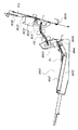
上記2つ折り処理及び折目強化処理を行うシート処理装置として、例えば特許文献1に開示されているものがある。これは、図19及び図20に示すように、先ず集積部70で複数枚のシートを整合した後、その搬送方向中央部を針綴じする。そして、針綴じしたシート束Tを、針綴じ部を先頭にして2つ折りするように第1折りローラ対71に通すことで2つ折り処理する。次に折り処理後の折り部に対し、第1折りローラ対71とは別の第2折りローラ(プレスローラ)72でニップし、この状態で第2折りローラ72をシート束Tの折目方向(搬送方向に対して直交方向)に移動させることで折目を強化する。その後、折目強化処理された折りシート束を、第1折りローラ対71によりトレイ73に排出する。   An example of a sheet processing apparatus that performs the above-described bi-folding process and crease reinforcement process is disclosed in Patent Document 1. As shown in FIGS. 19 and 20, first, the stacking unit 70 aligns a plurality of sheets, and then staples the central portion in the conveyance direction. Then, the staple-bound sheet bundle T is folded in two by passing it through the first folding roller pair 71 so as to be folded in half with the staple-bound portion at the head. Next, the folded portion after the folding process is nipped by a second folding roller (press roller) 72 different from the first folding roller pair 71, and in this state, the second folding roller 72 is fold direction of the sheet bundle T The fold is strengthened by moving in the direction orthogonal to the transport direction. Thereafter, the folded sheet bundle subjected to the crease reinforcement processing is discharged to the tray 73 by the first folding roller pair 71.

特開2003−182928号公報JP 2003-182928 A

上記のシート処理装置では、トレイ73に収容された折りシート束の後端は、折目強化処理のために折目方向に移動する第2折りローラ72との干渉を避けるべく、この動作領域外(搬送方向下流位置)でなければならない。しかしながら、トレイ73を第2折りローラ72から大きく離した位置に設置すると、次の折りシート束を排出する第1折りローラ対71との間隔が広くなってしまう。この場合、排出される折りシート束の先端が垂れ易くなり、排出される折りシート束の先端がトレイ73に収容された折りシート束の後端に引っかかるおそれがある。このため、シート詰まり、積載不良、シート折れなどの問題を引き起こすおそれがある。   In the sheet processing apparatus described above, the rear end of the folded sheet bundle accommodated in the tray 73 is outside this operation region in order to avoid interference with the second folding roller 72 that moves in the fold direction for the crease strengthening process. (Downstream position in the transport direction). However, if the tray 73 is installed at a position far away from the second folding roller 72, the distance from the first folding roller pair 71 that discharges the next folded sheet bundle becomes wide. In this case, the leading end of the folded folded sheet bundle is likely to sag, and the leading end of the folded folded sheet bundle may be caught by the trailing end of the folded sheet bundle accommodated in the tray 73. This may cause problems such as sheet jamming, stacking failure, and sheet folding.

そこで、トレイ73上に収容された折りシート束を、次の折りシート束排出時に排出方向上流側に移動させ、既にトレイ73に収容された折りシート束上に次に排出される折りシート束先端が積載されるようにする方法も提案されている。   Therefore, the folded sheet bundle accommodated on the tray 73 is moved upstream in the discharging direction when the next folded sheet bundle is discharged, and the leading end of the folded sheet bundle to be discharged next onto the folded sheet bundle already accommodated in the tray 73 There is also proposed a method for loading the vehicle.

しかし、上記積載方法の場合、既収容折りシート束のすべてが均一に上流側に移動しないと、瓦積み状の積載が崩れ、シートの種類によっては、折りシート束の開放端(後端)が開いてしまい、その中に次のシート束が入り込む可能性がある。このため、積載性を保つためには移動させる量に制限があった。   However, in the case of the above stacking method, if all of the already-folded folded sheet bundles do not move uniformly upstream, the stacking of the tile stack will collapse, and depending on the type of sheet, the open end (rear end) of the folded sheet bundle may be There is a possibility that the next sheet bundle will enter inside. For this reason, in order to maintain the loadability, the amount of movement has been limited.

本発明は上記点に鑑みてなされたものであり、その目的は、シートの種類が異なる場合でも、確実に積載排出可能なシート処理装置及びこれを備えた画像形成装置を提供するものである。   The present invention has been made in view of the above points, and an object of the present invention is to provide a sheet processing apparatus capable of reliably stacking and discharging even when the types of sheets are different, and an image forming apparatus including the sheet processing apparatus.

上記課題を解決するための本発明における代表的な手段は、シート束を折り処理した折りシート束を積載する積載手段と、前記積載手段に前記折りシート束の折目を先頭にして排出する排出手段と、前記積載手段に排出された折りシート束をシート束排出方向下流または上流に移送するための移送手段と、を有し、前記積載手段へ折りシート束を排出するときに、前記積載手段に既に排出されている既積載折りシート束の排出方向上流端部が前記積載手段に排出される後続折りシート束の排出方向下流端よりも上流に位置するように前記後続折りシート束のシート情報に応じて前記既積載折りシート束を前記移送手段によりシート排出方向上流に移送することを特徴とする。 Representative means in the present invention for solving the above problems are a stacking unit that stacks a folded sheet bundle obtained by folding a sheet bundle, and a discharge that discharges the folded sheet bundle to the stacking unit at the top. And a transfer means for transferring the folded sheet bundle discharged to the stacking means downstream or upstream in the sheet bundle discharge direction, and when the folded sheet bundle is discharged to the stacking means , the stacking means The sheet information of the subsequent folded sheet bundle is positioned upstream of the downstream end in the discharge direction of the subsequent folded sheet bundle discharged to the stacking unit. Accordingly, the already loaded folded sheet bundle is transported upstream in the sheet discharge direction by the transport means.

本発明にあっては、積載手段に積載された折りシート束の後端位置がシートの種類に応じて決定されるために、折りシート束の先端が垂れながら排出される場合であっても、スムーズな積載動作が可能となる。   In the present invention, since the rear end position of the folded sheet bundle stacked on the stacking unit is determined according to the type of the sheet, even if the leading end of the folded sheet bundle is discharged while dripping, Smooth loading operation is possible.

次に本発明の一実施形態に係るシート処理装置及びこれを備えた画像形成装置について、図面を参照して説明する。   Next, a sheet processing apparatus and an image forming apparatus including the sheet processing apparatus according to an embodiment of the present invention will be described with reference to the drawings.

〔第1実施形態〕
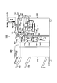
図1は第1実施形態に係るシート処理装置を備えた画像形成装置である複写機の断面説明図であり、図2はシート処理装置の断面説明図である。
[First Embodiment]
FIG. 1 is a cross-sectional explanatory view of a copying machine which is an image forming apparatus provided with a sheet processing apparatus according to the first embodiment, and FIG. 2 is a cross-sectional explanatory view of the sheet processing apparatus.

(全体構成)
本実施形態の画像形成装置としての複写機1000は、図1に示すように、原稿給送部100、イメージリーダ部200及び画像形成装置本体であるプリンタ部300、折り処理部400、フィニッシャ500、中綴じ製本部800(図2参照)、インサータ900等を有する。上記折り処理部400、中綴じ製本部800、インサータ900等は、オプションとして装備することができる。
(overall structure)
As shown in FIG. 1, a copying machine 1000 as an image forming apparatus according to the present embodiment includes a document feeding unit 100, an image reader unit 200, a printer unit 300 as a main body of the image forming apparatus, a folding processing unit 400, a finisher 500, It has a saddle stitch bookbinding section 800 (see FIG. 2), an inserter 900, and the like. The folding processing unit 400, the saddle stitch bookbinding unit 800, the inserter 900, and the like can be provided as options.

図1を参照して、原稿給送部100のトレイ1001上には、ユーザから見て正立状態で、且つ、フェイスアップ状態(画像が形成されている面が上向きの状態)で原稿がセットされているものとし、原稿の綴じ位置は、原稿の左端部に位置するものとする。トレイ1001上にセットされた原稿は、原稿給送部100により先頭ページから順に1枚ずつ左方向(図の矢印方向)、即ち、綴じ位置を先端にして搬送される。そして、更に該原稿は、湾曲したパスを介してプラテンガラス102上を左方向から右方向へ搬送され、その後、排出トレイ112上に排出される。なお、この際、スキャナユニット104は、所定の位置に保持された状態にあり、該スキャナユニット104上を原稿が左から右へと通過することにより原稿の読取処理が行われる(原稿流し読み)。   Referring to FIG. 1, a document is set on tray 1001 of document feeder 100 in an upright state as viewed from the user and in a face-up state (the surface on which an image is formed is upward). It is assumed that the binding position of the document is located at the left end portion of the document. Documents set on the tray 1001 are conveyed by the document feeder 100 one by one from the first page in the left direction (arrow direction in the figure), that is, with the binding position as the leading edge. Further, the original is further conveyed from the left to the right on the platen glass 102 via a curved path, and then discharged onto the discharge tray 112. At this time, the scanner unit 104 is held in a predetermined position, and the document reading process is performed when the document passes from the left to the right on the scanner unit 104 (document flow scanning). .

原稿がプラテンガラス102上を通過する際、該原稿は、スキャナユニット104のランプ103により照射され、その原稿からの反射光がミラー105,106,107、レンズ108を介してイメージセンサ109に導かれる。   When the document passes over the platen glass 102, the document is irradiated by the lamp 103 of the scanner unit 104, and the reflected light from the document is guided to the image sensor 109 via the mirrors 105, 106, 107 and the lens 108. .

なお、原稿給送部100により搬送した原稿をプラテンガラス102上に一旦停止させ、その状態でスキャナユニット104を左から右へと移動させることにより原稿の読取処理を行うこともできる(原稿固定読み)。原稿給送部100を使用しないで原稿の読み取りを行わせる場合、ユーザは、原稿給送部100を持ち上げ、プラテンガラス102上に原稿をセットする。この場合、上述した原稿固定読みが行なわれる。   It is also possible to perform document reading processing by temporarily stopping the document conveyed by the document feeder 100 on the platen glass 102 and moving the scanner unit 104 from left to right in this state (document fixed reading). ). When reading a document without using the document feeding unit 100, the user lifts the document feeding unit 100 and sets the document on the platen glass 102. In this case, the above-described original fixed reading is performed.

イメージセンサ109により読み取られた原稿の画像データは、所定の画像処理が施されて露光制御部110へ送られる。露光制御部110は、画像信号に応じたレーザ光を出力する。このレーザ光出力により、静電記録方式を用いた画像形成手段により画像が形成される。   The document image data read by the image sensor 109 is subjected to predetermined image processing and sent to the exposure control unit 110. The exposure control unit 110 outputs laser light corresponding to the image signal. With this laser beam output, an image is formed by image forming means using an electrostatic recording system.

すなわち、前記レーザ光は、ポリゴンミラー110aにより走査されながら感光体ドラム111上に照射され、感光体ドラム111上には走査されたレーザ光に応じた静電潜像が形成される。   That is, the laser beam is irradiated onto the photosensitive drum 111 while being scanned by the polygon mirror 110a, and an electrostatic latent image corresponding to the scanned laser beam is formed on the photosensitive drum 111.

感光体ドラム111上に形成された静電潜像は、現像器113により現像され、トナー像として可視化される。一方、記録シートは、カセット114,115、手差し給送部125、両面搬送パス124の何れかから転写部116へ搬送される。そして、可視化されたトナー像が転写部116において記録シートPに転写される。転写後の記録シートは、定着部177にて定着処理が施される。   The electrostatic latent image formed on the photosensitive drum 111 is developed by the developing unit 113 and visualized as a toner image. On the other hand, the recording sheet is conveyed to the transfer unit 116 from any of the cassettes 114 and 115, the manual feeding unit 125, and the double-sided conveyance path 124. Then, the visualized toner image is transferred to the recording sheet P in the transfer unit 116. The recording sheet after the transfer is subjected to a fixing process by a fixing unit 177.

そして、定着部177を通過した記録シートをフラッパ121により一旦パス122に導き、記録シートの後端がフラッパ121を抜けた後に、スイッチバックさせ、フラッパ121により排出ローラ118へ搬送する。そして、排出ローラ118により該記録シートをプリンタ部300から排出する。これによりトナー像が形成された面を下向きの状態(フェイスダウン)でプリンタ部300から排出できる(反転排出)。   The recording sheet that has passed through the fixing unit 177 is once guided to the path 122 by the flapper 121, and after the trailing end of the recording sheet has passed through the flapper 121, the recording sheet is switched back and conveyed to the discharge roller 118 by the flapper 121. The recording sheet is discharged from the printer unit 300 by the discharge roller 118. Accordingly, the surface on which the toner image is formed can be discharged from the printer unit 300 in a downward state (face-down) (reverse discharge).

上述したように、フェイスダウンで記録シートを機外に排出する。これにより、先頭ページから順に画像形成処理を行う場合、例えば、原稿給送部100を使用して画像形成処理を行う場合や、コンピュータからの画像データに対する画像形成処理を行う場合にページ順序を揃えることができる。   As described above, the recording sheet is discharged out of the apparatus face down. As a result, when the image forming process is performed in order from the first page, for example, when the image forming process is performed using the document feeder 100, or when the image forming process is performed on the image data from the computer, the page order is aligned. be able to.

また、シートの両面に画像形成処理を行う場合は、シートを定着部177からまっすぐ排出ローラ118方向へと導き、シートの後端がフラッパ121を抜けた直後にシートをスイッチバックし、フラッパ121により両面搬送パスへと導く。   When image forming processing is performed on both sides of the sheet, the sheet is guided straight from the fixing unit 177 toward the discharge roller 118, and the sheet is switched back immediately after the trailing edge of the sheet passes through the flapper 121. Guide to the duplex transport path.

(折り処理部及びフィニッシャ)
次に、折り処理部400及びフィニッシャ500の構成について、図1及び図2を参照して説明する。
(Folding section and finisher)
Next, configurations of the folding processing unit 400 and the finisher 500 will be described with reference to FIGS. 1 and 2.

折り処理部400は、プリンタ部300から排出されたシートを導入し、フィニッシャ500側に導くための搬送パス131を有する。搬送パス131上には、搬送ローラ対130及び133が設けられている。また、搬送ローラ対133の近傍に設けられた切替フラッパ135は、搬送ローラ対130により搬送されたシートを折りパス136またはフィニッシャ500側に導くためのものである。   The folding processing unit 400 has a conveyance path 131 for introducing the sheet discharged from the printer unit 300 and guiding it to the finisher 500 side. On the conveyance path 131, conveyance roller pairs 130 and 133 are provided. A switching flapper 135 provided in the vicinity of the conveying roller pair 133 is for guiding the sheet conveyed by the conveying roller pair 130 to the folding path 136 or the finisher 500 side.

シートの折り処理を行う場合、切替フラッパ135を折りパス136側に切り替え、シートを折りパス136に導く。折りパス136に導かれたシートは、折りローラまで搬送され、Z型に折り畳まれる。一方、折り処理を行わない場合は、切替フラッパ135をフィニッシャ側500に切り替え、プリンタ部300から排出されたシートを、搬送パス131を介して直接送り込む。   When the sheet folding process is performed, the switching flapper 135 is switched to the folding path 136 and the sheet is guided to the folding path 136. The sheet guided to the folding path 136 is conveyed to the folding roller and folded into a Z shape. On the other hand, when the folding process is not performed, the switching flapper 135 is switched to the finisher side 500, and the sheet discharged from the printer unit 300 is directly fed through the conveyance path 131.

折りパス136を搬送されたシートは、ストッパ137に先端を突き当てることで形成されるループが、折りローラ140,141により折られる。この折り曲げ部を、上方のストッパ143に突き当てることで形成された部ループを、折りローラ141,142により更に折ることで、シートはZ折りされる。このZ折りシートは、搬送パス145を介して搬送パス131に送られ、搬送ローラ対133によりシート搬送方向下流側(以下、単に「下流側」という)に付設されたフィニッシャ500に排出される。なお、折り処理部400による折り処理動作は選択的に行われる。   The sheet conveyed through the folding path 136 is folded by the folding rollers 140 and 141 by a loop formed by abutting the leading end against the stopper 137. The sheet is Z-folded by further folding the loop formed by abutting the bent portion against the upper stopper 143 by the folding rollers 141 and 142. The Z-folded sheet is sent to the conveyance path 131 via the conveyance path 145, and is discharged to the finisher 500 attached to the downstream side in the sheet conveyance direction (hereinafter simply referred to as “downstream side”) by the conveyance roller pair 133. Note that the folding processing operation by the folding processing unit 400 is selectively performed.

フィニッシャ500は、折り処理部400を介して搬送されたプリンタ部300からのシートを取り込み、取り込んだ複数のシートを整合して、1つのシート束として束ねる処理を行う。また、フィニッシャ500は、シート束の後端側をステイプルするステイプル処理(綴じ処理)、ソート処理、ノンソート処理等のシートの処理を行うためのものである。   The finisher 500 performs processing to take in sheets from the printer unit 300 conveyed via the folding processing unit 400, align the plurality of taken-in sheets, and bundle them as one sheet bundle. The finisher 500 is for performing sheet processing such as stapling processing (binding processing) for stapling the trailing end side of the sheet bundle, sorting processing, non-sorting processing, and the like.

図2に示すように、フィニッシャ500は、折り処理部400を介して搬送されたシートを装置内部に取り込むための搬送パス520があり、この搬送パス520には複数の搬送ローラ対が設けられている。   As shown in FIG. 2, the finisher 500 has a conveyance path 520 for taking the sheet conveyed through the folding processing unit 400 into the apparatus, and the conveyance path 520 is provided with a plurality of conveyance roller pairs. Yes.

搬送パス520の途中にはパンチユニット530が設けられており、パンチユニット530は必要に応じて動作を行い、搬送されるシートの後端部に穴あけ(穿孔)処理を行う。   A punch unit 530 is provided in the middle of the conveyance path 520, and the punch unit 530 operates as necessary to perform a punching process at the rear end of the conveyed sheet.

搬送パス520の終端に設けられたフラッパ513は、下流側に繋がれた上排出パス521と下排出パス522とに経路を切り替えるものである。上排出パス521は、上スタックトレイへの排出を行う。一方、下排出パス522は、処理トレイ550への排出を行う。処理トレイ550に排出されるシートは順次整合処理されながら束状に収容され、プリンタ部300に設けられた操作部1(図5)からの設定に応じて、仕分け処理やステイプル処理が行われ、その後、束排出ローラ対551によりスタックトレイ700,701に排出される。   A flapper 513 provided at the end of the transport path 520 switches the route between an upper discharge path 521 and a lower discharge path 522 connected to the downstream side. The upper discharge path 521 performs discharge to the upper stack tray. On the other hand, the lower discharge path 522 discharges to the processing tray 550. The sheets discharged to the processing tray 550 are accommodated in a bundle while being sequentially aligned, and according to settings from the operation unit 1 (FIG. 5) provided in the printer unit 300, sorting processing and stapling processing are performed. Thereafter, the sheet is discharged to the stack trays 700 and 701 by the bundle discharge roller pair 551.

なお、上記したステイプル処理はステイプラ560により行われるものであり、ステイプラ560はシート幅方向に移動可能となっており、シートの任意の位置にステイプルすることができる。   Note that the above-described stapling process is performed by the stapler 560, and the stapler 560 can be moved in the sheet width direction and can be stapled at an arbitrary position on the sheet.

(中綴じ製本部)
次に、中綴じ製本部800の構成を説明する。前記下排出パス522の途中に設けられた切替フラッパ514により、右側に切り替えられたシートは、図2に示すサドル排出パス523を通過して、中綴じ製本部800へ送られる。シートはサドル入口ローラ対801に受け渡され、サイズに応じてソレノイドにより動作するフラッパ802により搬入口を選択されて、中綴じ製本部800の収納ガイド803内に搬入される。搬入されたシートは滑りローラ804により先端が可動式のシート位置決め部材805に接するまで搬送される。サドル入口ローラ対801と滑りローラ804はモータM1により駆動される。また、収納ガイド803の途中位置には、収納ガイド803を挟んで対向配置されたステイプラ820が設けられている。ステイプラ820は、ステイプル針を突き出すドライバー820aと、突き出された針を折り曲げるアンビル820bとに分割されている。なお、前記のシート位置決め部材805は、シート搬入時において、シート搬送方向中央部が、このステイプラ820の綴じ位置になる位置で停止する。シート位置決め部材805は、モータM2の駆動を受けて移動自在であり、シートサイズに応じて位置を変える。
(Saddle stitch bookbinding)
Next, the configuration of the saddle stitch bookbinding unit 800 will be described. The sheet switched to the right side by the switching flapper 514 provided in the middle of the lower discharge path 522 passes through the saddle discharge path 523 shown in FIG. The sheet is delivered to a pair of saddle entrance rollers 801, a carry-in entrance is selected by a flapper 802 operated by a solenoid according to the size, and is carried into a storage guide 803 of the saddle stitch bookbinding portion 800. The loaded sheet is conveyed by the sliding roller 804 until the leading end contacts the movable sheet positioning member 805. The saddle entrance roller pair 801 and the sliding roller 804 are driven by a motor M1. In addition, a stapler 820 is provided in the middle of the storage guide 803 so as to face the storage guide 803. The stapler 820 is divided into a driver 820a that projects a staple needle and an anvil 820b that bends the projected needle. The sheet positioning member 805 stops at a position where the center portion in the sheet conveyance direction becomes the binding position of the stapler 820 when the sheet is carried in. The sheet positioning member 805 is movable under the driving of the motor M2, and changes its position according to the sheet size.

ステイプラ820の下流側には、折りローラ対810(810a,810b)が設けられており、折りローラ対810の対向位置には、突き出し部材830が設けられている。この突き出し部材830は、収納ガイド803から退避した位置をホームポジションとしていて、モータM3の駆動により収納されたシート束に向けて突き出すことにより、シート束を折りローラ対810のニップに押し込みながら折り畳むものである。突き出し部材830はその後、再びホームポジションに戻る。なお、折りローラ対810間には、束に折り目付けをするのに充分な圧F1が不図示のバネにより掛けられている。折り目付けされたシート束は、折りシート束の折目を先頭にして排出する排出手段となる第1折搬送ローラ対811(811a,811b)、第2折搬送ローラ対812(812a,812b)を介して、折り束トレイ840に排出される。なお、第1折搬送ローラ対811、及び第2折搬送ローラ対812にも、折り目付けされた束を搬送、停止させるのに充分な圧F2、F3が掛けられている。   A folding roller pair 810 (810a, 810b) is provided on the downstream side of the stapler 820, and a protruding member 830 is provided at a position opposite to the folding roller pair 810. The projecting member 830 has a position retracted from the storage guide 803 as a home position, and folds while pushing the sheet bundle into the nip of the pair of folding rollers 810 by projecting toward the sheet bundle stored by driving the motor M3. It is. Thereafter, the protruding member 830 returns to the home position again. In addition, a pressure F1 sufficient to crease the bundle is applied between the pair of folding rollers 810 by a spring (not shown). The creased sheet bundle includes a first fold conveyance roller pair 811 (811a, 811b) and a second fold conveyance roller pair 812 (812a, 812b), which serve as discharge means for discharging the fold of the folded sheet bundle at the head. Through the folding tray 840. The first fold conveyance roller pair 811 and the second fold conveyance roller pair 812 are also subjected to pressures F2 and F3 sufficient to convey and stop the folded bundle.

折りローラ対810、第1折搬送ローラ対811、第2折搬送ローラ対812は、同一のモータM4(図2)により等速回転する。   The folding roller pair 810, the first folding transport roller pair 811 and the second folding transport roller pair 812 are rotated at the same speed by the same motor M4 (FIG. 2).

また、ステイプラ820で綴じられたシート束を折り畳む場合は、ステイプル処理終了後に、シート束のステイプル位置が折りローラ対810のニップ位置にくるように、シート位置決め部材805を、ステイプル処理時の場所から所定距離降下させる。これによりステイプル処理を施した位置を中心にしてシート束を折り畳むことができる。   Further, when folding the sheet bundle bound by the stapler 820, the sheet positioning member 805 is moved away from the position at the time of the stapling process so that the staple position of the sheet bundle comes to the nip position of the pair of folding rollers 810 after the stapling process is completed. Descent a predetermined distance. Accordingly, the sheet bundle can be folded around the position where the stapling process is performed.

また、図2において、815は折りローラ対810a,810bの外周面の外側をまわり込みながら収納ガイド803に突き出した面を持ち、収納ガイド803に収納されたシートを整合する整合板対である。この整合板対815は、モータM5の駆動を受けて、シートに対し、挟み込み方向に移動することによって、シートの幅方向の位置決めを行う。   In FIG. 2, reference numeral 815 denotes a pair of alignment plates that have a surface protruding to the storage guide 803 while wrapping around the outer peripheral surfaces of the pair of folding rollers 810 a and 810 b and align sheets stored in the storage guide 803. The alignment plate pair 815 is positioned in the width direction of the sheet by being driven by the motor M5 and moving in the sandwiching direction with respect to the sheet.

そして、前記第2折搬送ローラ対812の下流側には、折り束トレイ840と空間的に重なって折目処理手段となるプレスユニット860が設けられている。このプレスユニット860は、折り部材となるプレスローラ対861を支持したプレスホルダ862を有し、プレスローラ対861が折目をニップした状態で、プレスホルダ862を折目に沿って移動させることで、折目を強化するように折目処理するものである。   A press unit 860 serving as a crease processing unit is provided on the downstream side of the second fold conveying roller pair 812 so as to overlap the fold tray 840 spatially. The press unit 860 includes a press holder 862 that supports a pair of press rollers 861 serving as folding members, and the press holder 862 is moved along the fold while the pair of press rollers 861 nips the fold. The fold processing is performed so as to strengthen the fold.

(プレスユニット)
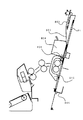
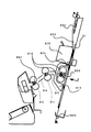
次に、プレスユニット860について図3及び図4を参照して説明する。図3は折目プレスユニットの斜視図であり、図4はプレスユニットの内部説明図である。
(Press unit)
Next, the press unit 860 will be described with reference to FIGS. FIG. 3 is a perspective view of the crease press unit, and FIG. 4 is an explanatory diagram of the inside of the press unit.

プレスユニット860は、図3に示すように、主要部を組み込んだベース板金863と2本のスライドシャフト864,865を有し、前後側板に固定されている。2本のスライドシャフト864,865は、シート束の排出方向と直交するシート幅方向に延びて並設されていて、それぞれプレスホルダ862に固定されたスライド軸受874,875に貫通してプレスホルダ862を支持している。   As shown in FIG. 3, the press unit 860 includes a base sheet metal 863 incorporating a main part and two slide shafts 864 and 865, and is fixed to the front and rear side plates. The two slide shafts 864 and 865 are arranged side by side in the sheet width direction perpendicular to the sheet bundle discharge direction, and penetrate through the slide bearings 874 and 875 fixed to the press holder 862, respectively. Support.

前記プレスホルダ862にはプレスローラ対861が回動可能に取り付けられ、このプレスローラ対861に対するシートガイド871が取り付けられている。   A press roller pair 861 is rotatably attached to the press holder 862, and a sheet guide 871 for the press roller pair 861 is attached.

また、図4に示すように、プレスアーム873a,873bはフレーム839に固定された揺動軸874a,874bに、軸受を介して揺動可能に支持されている。プレスアーム873a,873bの一端部とフレーム839には、引張バネ875a,875bが掛けられていて、プレスローラ対861a,861bは互いに近づく方向の圧を有してニップしている。但し、プレスローラ対861にシート束が挿入されると、プレスアーム873a,873bは揺動軸874a,874bを支点に回転し、ローラ間が離間される。   Further, as shown in FIG. 4, the press arms 873a and 873b are supported by swinging shafts 874a and 874b fixed to the frame 839 so as to be swingable through bearings. Tensile springs 875a and 875b are hung on one end of the press arms 873a and 873b and the frame 839, and the pair of press rollers 861a and 861b are nipped with a pressure in a direction approaching each other. However, when a sheet bundle is inserted into the press roller pair 861, the press arms 873a and 873b rotate about the pivot shafts 874a and 874b, and the rollers are separated from each other.

更に、図3に示すギア883は前記スライドシャフト864,865と平行に伸びてベース板金863に固定されたラックギア851と噛合っている。そして、モータM6が回転すると、タイミングベルト868の移動に伴い、プレスホルダ862はスライドシャフト864,865に支持されながら移動する。この移動時には、プレスホルダ862のギア883はラックギア851と噛合いながら回転する。このため、前記ギア883と図示しないギア列で連結したプレスローラ対861a,861bにも駆動が伝達される。なお、プレスホルダ862の移動速度と、2つのプレスローラ対861a,861bの周速度は等速になるように、前記各ギア列は設定されている。   Further, the gear 883 shown in FIG. 3 meshes with a rack gear 851 that extends in parallel with the slide shafts 864 and 865 and is fixed to the base metal plate 863. When the motor M6 rotates, the press holder 862 moves while being supported by the slide shafts 864 and 865 as the timing belt 868 moves. During this movement, the gear 883 of the press holder 862 rotates while meshing with the rack gear 851. For this reason, the drive is also transmitted to the pair of press rollers 861a and 861b connected to the gear 883 through a gear train (not shown). The gear trains are set so that the moving speed of the press holder 862 and the peripheral speeds of the two press roller pairs 861a and 861b are constant.

折りローラ対810a,810bで折られた折りシート束は、プレスローラ対861にて折目を強化する折目強化処理される際には、処理されるサイズに関わらず、折りシート束は、2つ以上のローラ対で保持される。このように保持することにより、折目強化処理される折りシート束がプレスローラ対861の移動によってずれてしまうことはない。なお、折目強化処理する際の折りシート束の先端停止位置(プレス先端位置)は、サイズに関わらずプレスローラ対861との相対関係が一定になるように、図2に示す搬送ガイド814に設けられたセンサ884を利用して制御されている。   When the folded sheet bundle folded by the pair of folding rollers 810a and 810b is subjected to the crease reinforcement processing for strengthening the fold by the press roller pair 861, the folded sheet bundle is 2 regardless of the size to be processed. Held by two or more pairs of rollers. By holding in this way, the folded sheet bundle subjected to the crease strengthening process is not displaced by the movement of the press roller pair 861. Note that the leading edge stop position (press leading edge position) of the folded sheet bundle at the time of the crease strengthening process is the same as that of the conveyance guide 814 shown in FIG. Control is performed using a provided sensor 884.

一方、折目強化処理する際の後端位置(プレス後端位置)は、後端が収納ガイド803等で規制され、後端が開いてしまわないように、各部の配置が決定されている。更に、プレス後端位置は前記収納ガイド803の領域外となるように、各部の配置が決定されている。従って、プレスローラ対861で折目強化処理されている間も、後続シート束を形成するシートの収納ガイド803への収納、整合動作を可能にしている。これは装置の生産性向上に寄与するものである。   On the other hand, the rear end position (press rear end position) at the time of the crease strengthening process is determined so that the rear end is regulated by the storage guide 803 and the rear end is not opened. Further, the arrangement of each part is determined so that the press rear end position is outside the area of the storage guide 803. Accordingly, even during the crease strengthening process by the press roller pair 861, the storage and alignment operations of the sheet forming the succeeding sheet bundle in the storage guide 803 are enabled. This contributes to an improvement in device productivity.

また、図2に示すシート束搬送ガイド813,814は、プレスホルダ862を含めて、収納ガイド803と後端ガイドの間に収まるように配置されている。これは、上述した折り束トレイ840とプレスユニット860の空間的重ね配置とともに、装置搬送方向の大きさを小さくする効果がある。   Further, the sheet bundle conveyance guides 813 and 814 shown in FIG. 2 including the press holder 862 are arranged so as to fit between the storage guide 803 and the rear end guide. This has the effect of reducing the size in the apparatus transport direction along with the spatial overlap arrangement of the folding tray 840 and the press unit 860 described above.

(折り束トレイ)
次にシート束を折り処理した折りシート束を積載する積載手段である折り束トレイ840の構成について、図2を用いて説明する。折り束トレイ840は、シート束の排出方向に連続して第1積載面841、第2積載面842、第3積載面843が順に設けられていて、第2折搬送ローラ対812から排出される折りシート束を積載する。
(Folding tray)
Next, the configuration of the folding tray 840 serving as a stacking unit for stacking folded sheet bundles obtained by folding the sheet bundle will be described with reference to FIG. The folding tray 840 is provided with a first stacking surface 841, a second stacking surface 842, and a third stacking surface 843 in order in the sheet bundle discharging direction, and is discharged from the second folding conveying roller pair 812. Stack folded sheet bundles.

第1積載面841は、プレスユニット860の下方にあって、プレスユニット860と鉛直方向の空間が一部重なっており、搬送方向の下流側が下方に傾斜している。この傾斜角は、前述した第2折搬送ローラ対812による折りシート束の排出角度と略等しくなるように構成され、傾斜の頂点は、プレスユニット860の動作に干渉しない高さまで極力上げられている。   The first loading surface 841 is below the press unit 860, and a space in the vertical direction partially overlaps the press unit 860, and the downstream side in the transport direction is inclined downward. This inclination angle is configured to be substantially equal to the discharge angle of the folded sheet bundle by the second folding conveying roller pair 812 described above, and the apex of the inclination is raised as much as possible to a height that does not interfere with the operation of the press unit 860. .

第1積載面841及び第2積載面842には、排出された折りシート束をシート束排出方向下流側または上流側に移送するための移送手段となるコンベアベルト844,845が設けられていて、両ベルト844,845の一方端を屈曲部付近の駆動プーリ846に掛けられている。他方端は、第1コンベアベルト844はアイドラプーリ847に、第2コンベアベルト845はアイドラプーリ848に、積載面と平行になるように掛けられている。そして駆動プーリ846の軸に連結されたコンベアモータM7の駆動を受けて、それぞれのコンベアベルト844,845が同一の方向に正逆回転する。   On the first stacking surface 841 and the second stacking surface 842, conveyor belts 844 and 845 serving as transfer means for transferring the discharged folded sheet bundle to the downstream side or the upstream side in the sheet bundle discharge direction are provided. One ends of both belts 844 and 845 are hung on a driving pulley 846 near the bent portion. At the other end, the first conveyor belt 844 is hung on the idler pulley 847 and the second conveyor belt 845 is hung on the idler pulley 848 so as to be parallel to the loading surface. The conveyor belts 844 and 845 rotate forward and backward in the same direction under the drive of the conveyor motor M7 connected to the shaft of the drive pulley 846.

また、第1積載面841には、プレスユニット860の動作領域の直下に積載されたシート束を検出可能な束検知センサ849が設けられており、検出信号に基づき排出された折りシート束の積載位置が制御される。   In addition, the first stacking surface 841 is provided with a bundle detection sensor 849 that can detect a sheet bundle stacked immediately below the operation area of the press unit 860, and stacks the folded sheet bundle discharged based on the detection signal. The position is controlled.

第3積載面843は、第2積載面842に対して段差を持って平行であり、伸縮することで第2積載面の下部から延出し、また収納可能となっている。そして、第3積載面843を第2積載面842の下部に収納した場合には(破線位置)、その位置に床面からアイドラプーリ848までの高さの収納ボックス850(破線図)を置くことで、束の積載量を増やすことができる。   The third loading surface 843 is parallel to the second loading surface 842 with a step, and extends and retracts from the lower portion of the second loading surface by expanding and contracting. When the third loading surface 843 is stored below the second loading surface 842 (broken line position), a storage box 850 (broken line diagram) having a height from the floor surface to the idler pulley 848 is placed at that position. Thus, the stacking capacity of the bundle can be increased.

(制御部)
図5は、複写装置1000のブロック図である。CPU回路部150は、プリンタ部300に設けられ、CPU(不図示)を有する。そして、ROM151に格納された制御プログラム及び操作部1の設定に従い、原稿給送制御部101、イメージリーダ制御部201、画像信号制御部202、プリンタ制御部301、折り処理制御部401、フィニッシャ制御部501、外部I/F203を制御する。操作部1は、プリンタ部300に設けられ、画像形成に関する各種機能を設定するための複数のキー、設定状態を表示するための表示部等を有する。ここで、ユーザによる各キーの操作に対応するキー信号をCPU回路部150に出力すると共に、CPU回路部150からの信号に基づき対応する情報を表示部に表示する。また、ユーザは、操作部1からシートの種類を入力することが可能である。
(Control part)
FIG. 5 is a block diagram of the copying apparatus 1000. The CPU circuit unit 150 is provided in the printer unit 300 and includes a CPU (not shown). Then, according to the control program stored in the ROM 151 and the setting of the operation unit 1, the document feeding control unit 101, the image reader control unit 201, the image signal control unit 202, the printer control unit 301, the folding processing control unit 401, the finisher control unit 501, the external I / F 203 is controlled. The operation unit 1 is provided in the printer unit 300 and includes a plurality of keys for setting various functions relating to image formation, a display unit for displaying a setting state, and the like. Here, a key signal corresponding to the operation of each key by the user is output to the CPU circuit unit 150, and corresponding information is displayed on the display unit based on the signal from the CPU circuit unit 150. Further, the user can input the sheet type from the operation unit 1.

RAM152は、制御データを一時的に保持するための領域や、制御に伴う演算の作業領域として用いられる。外部I/F203は、複写装置1000と外部のコンピュータ204とのインタフェースであり、コンピュータ204からのプリントデータをビットマップ画像に展開し、画像データとして画像信号制御部202へ出力する。また、イメージリーダ制御部201から画像信号制御部202へは、イメージセンサ(不図示)で読み取った原稿の画像が出力される。プリンタ制御部301は、画像信号制御部202からの画像データを露光制御部(不図示)へ出力する。   The RAM 152 is used as an area for temporarily storing control data and a work area for operations associated with control. An external I / F 203 is an interface between the copying apparatus 1000 and an external computer 204. The print data from the computer 204 is developed into a bitmap image and output to the image signal control unit 202 as image data. Further, an image of a document read by an image sensor (not shown) is output from the image reader control unit 201 to the image signal control unit 202. The printer control unit 301 outputs the image data from the image signal control unit 202 to an exposure control unit (not shown).

フィニッシャ制御部501は、フィニッシャ500に設けられ、CPU回路部150と通信によるやり取りを行いながら、シート処理全般の制御を司る。フィニッシャ制御部501をCPU回路部150と一体的にプリンタ部300に設け、プリンタ部300から直接制御するようにしてもよい。   A finisher control unit 501 is provided in the finisher 500, and controls overall sheet processing while performing communication with the CPU circuit unit 150 through communication. The finisher control unit 501 may be provided in the printer unit 300 integrally with the CPU circuit unit 150, and may be directly controlled from the printer unit 300.

(製本排出動作)
次に上記構成に基づき、本実施形態における中綴じ製本排出について、シートの流れとともに各部の動作を説明する。
(Binding discharge operation)
Next, based on the above-described configuration, the operation of each unit will be described together with the flow of the sheet in the saddle stitch bookbinding discharge in the present embodiment.

ユーザにより、中綴じ製本モードが設定されると、適宜面付けされて画像形成されたシートが順次、プリンタ部300の排出ローラ118から排出される。   When the saddle stitch bookbinding mode is set by the user, sheets that are appropriately impositioned and image-formed are sequentially discharged from the discharge roller 118 of the printer unit 300.

シートは、折り処理部400を通過し、入口ローラ対に受け渡された後、搬送パス520を通過して、下排出パス522に進入する。その後のシートは、下排出パス522途中の切替フラッパ514によりサドル排出パス523に導かれる。   The sheet passes through the folding processing unit 400 and is transferred to the pair of entrance rollers, and then passes through the conveyance path 520 and enters the lower discharge path 522. The subsequent sheet is guided to the saddle discharge path 523 by the switching flapper 514 in the middle of the lower discharge path 522.

図6に示すように、シートのサイズに応じたフラッパ802にガイドされながら収納ガイド803に排出される。また、滑りローラ804の搬送力も受けながら、予めシートサイズに適合した位置で停止しているシート位置決め部材805に突き当てられて、搬送方向の位置決めがされる。   As shown in FIG. 6, the sheet is discharged to the storage guide 803 while being guided by a flapper 802 corresponding to the size of the sheet. Further, while receiving the conveying force of the sliding roller 804, it is abutted against a sheet positioning member 805 that has been stopped in advance at a position suitable for the sheet size, and is positioned in the conveying direction.

続いて、シート排出時には支障のない位置で待機していた整合板対815による挟み込み整合がなされて、シート幅方向の位置決めも行われる。以上のシート収容、整合動作が、シートが排出されるごとに行われる。   Subsequently, nipping alignment is performed by the alignment plate pair 815 that has been waiting at a position where there is no problem when the sheet is discharged, and positioning in the sheet width direction is also performed. The above sheet storage and alignment operations are performed each time a sheet is discharged.

シート束としての最終シートの整合が終了すると、ステイプラ820がシート束の搬送方向中央部を針綴じする。針綴じされたシート束P1は、図7に示すように、シート位置決め部材805の移動に伴って、下方(矢印D方向)に移動する。シート位置決め部材805は、シート束の中央部、すなわち針綴じ部が、折りローラ対810のニップに相当する位置で停止する。次に、待機位置にいた突き出し部材830が折りローラ対810のニップへと動き出し(矢印E方向)、図8に示すように、シート束P1はその中央部が折りローラ対810を押し広げながら移動して、ローラのニップに挿入されて折り畳まれる。このとき、折りローラ対810は第1折搬送ローラ対811、第2折搬送ローラ対812とともに、モータM4の駆動を受けて矢印方向に回転しており、折りシート束P1は折目を先頭にして搬送ガイド813,814内を搬送していく。   When the alignment of the final sheet as the sheet bundle is completed, the stapler 820 staples the central portion in the conveyance direction of the sheet bundle. As shown in FIG. 7, the staple-bound sheet bundle P1 moves downward (in the direction of arrow D) as the sheet positioning member 805 moves. In the sheet positioning member 805, the center portion of the sheet bundle, that is, the staple binding portion, stops at a position corresponding to the nip of the folding roller pair 810. Next, the protruding member 830 that has been in the standby position starts to move to the nip of the pair of folding rollers 810 (in the direction of arrow E), and as shown in FIG. 8, the center of the sheet bundle P1 moves while expanding the pair of folding rollers 810. Then, it is inserted into the nip of the roller and folded. At this time, the folding roller pair 810 and the first folding conveyance roller pair 811 and the second folding conveyance roller pair 812 are rotated in the direction of the arrow by the drive of the motor M4, and the folded sheet bundle P1 has the folding line at the head. Then, the inside of the conveyance guides 813 and 814 is conveyed.

そして、図9に示すように、折目がプレスローラ対861にニップさせる位置まで搬送されると、モータM4により停止する。停止位置制御は、折りシート束P1の先端をセンサ884が検出することによりなされる。このとき上述したように、折りシート束P1は搬送方向中心を挟んで、先端部を第2折搬送ローラ対812で、後端側を第1折搬送ローラ対811、及び折りシート束P1のサイズ(搬送方向の長さ)によっては、折りローラ対810で確実に保持される。なお、前記突き出し部材830は、突き出しが終了すると、再び退避位置へ移動する。   Then, as shown in FIG. 9, when the fold is conveyed to a position where it is nipped by the press roller pair 861, the motor M4 stops. The stop position control is performed by the sensor 884 detecting the leading end of the folded sheet bundle P1. At this time, as described above, the folded sheet bundle P1 is the size of the second folding conveyance roller pair 812 at the front end and the first folding conveyance roller pair 811 at the rear end side and the size of the folded sheet bundle P1 across the center in the conveyance direction Depending on the (length in the transport direction), the folding roller pair 810 can reliably hold it. The protruding member 830 moves to the retracted position again when the protruding is completed.

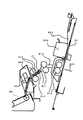
折目強化処理をする場合には、図10に示すように、折りシート束P1の搬送に先立ち、プレスホルダ862は、折りシート束P1のサイズ(幅方向)に応じた待機位置(奥側)にて待機している。そして、折りシート束P1の停止が完了して、折りシート束P1の折目がシートガイド871(鎖線)に挿入されるとモータM6の駆動を受け、プレスローラ対861を回転しながら、手前側(矢印F方向)への移動を開始する。   In the case of performing the crease strengthening process, as shown in FIG. 10, prior to the conveyance of the folded sheet bundle P1, the press holder 862 has a standby position (back side) corresponding to the size (width direction) of the folded sheet bundle P1. Waiting at Then, when the stop of the folded sheet bundle P1 is completed and the fold of the folded sheet bundle P1 is inserted into the sheet guide 871 (chain line), it is driven by the motor M6, and while rotating the press roller pair 861, The movement in the direction of arrow F is started.

その後、プレスローラ対861は停止保持されている折りシート束P1の折目付近の側面に当接するが、プレスプーラ861対自体が両側駆動で回転しているため、図11に示すように、スムーズに側面を駆け上って折目をニップすることができる。この効果は、折りシート束の厚みが増えても変わることはなく、プレスホルダ862の移動に同期して、応答遅れなしでシート束をプレスローラ対861にニップできるため、折りシート束P1に対してシワや破れ、ローラ跡等のダメージを与えない。   After that, the press roller pair 861 abuts against the side surface near the fold of the folded sheet bundle P1 held and stopped. However, since the press puller 861 pair itself is rotated by driving on both sides, as shown in FIG. You can run up to the side and nip the crease. This effect does not change even if the thickness of the folded sheet bundle is increased, and the sheet bundle can be nipped between the press roller pair 861 without delay in response in synchronization with the movement of the press holder 862. Do not cause damage such as wrinkles, tears, and roller marks.

プレスローラ対862が移動完了後、プレスユニット860はホームポジションに移動して、折りシート束P1の搬送方向の経路を開放する。   After the movement of the press roller pair 862 is completed, the press unit 860 moves to the home position and opens the path in the conveyance direction of the folded sheet bundle P1.

続いて、図13に示すように、モータM4により停止していた折りシート束P1は再び搬送が開始され、第2折搬送ローラ対812によって排出される。このとき、排出過程の折りシート束P1の先端は、自重により垂れながら移送されるが、第1積載面841までの落下量が短く、かつ第2折搬送ローラ対812によるシート束の排出角度と略等しい角度に設定された第1積載面841によりスムーズに受け渡される。従って、剛度の低い薄紙の場合でも、シート束先端が第1積載面841に着地することで座屈や丸まり等の不具合を伴わずに安定した束排出動作が行われる。   Subsequently, as shown in FIG. 13, the folded sheet bundle P <b> 1 stopped by the motor M <b> 4 starts to be transported again and is discharged by the second folding transport roller pair 812. At this time, the leading end of the folded sheet bundle P1 in the discharging process is transferred while drooping due to its own weight, but the amount of dropping to the first stacking surface 841 is short, and the discharge angle of the sheet bundle by the second folding conveying roller pair 812 is It is smoothly delivered by the first loading surface 841 set at substantially the same angle. Therefore, even in the case of thin paper with low rigidity, the bundle bundle can be stably discharged without causing problems such as buckling and curling because the leading edge of the sheet bundle lands on the first stacking surface 841.

(折り束トレイに既排出された折りシート束の移送動作)
次に前記シート束が排されるときに既に折り束トレイ840に排出積載されている折りシート束の動作制御について説明する。
(Transfer operation of folded sheet bundles already discharged to the folding tray)
Next, the operation control of the folded sheet bundle that has been discharged and stacked on the folded bundle tray 840 when the sheet bundle is discharged will be described.

図14に示すように、コンベアベルト844,845は、コンベアモータM7によって所定のタイミングで搬送方向の回転が開始され、折り束トレイ840に排出された折りシート束P1を移送する。そして折りシート束P1の後端を束検知センサ849が検出するとコンベアモータM7は停止する(第1積載位置)。上述したように束検知センサ849は、プレスユニット860の動作領域の直下に配設されているため、停止した折りシート束P1の後端もプレスユニット860の動作領域外である。   As shown in FIG. 14, the conveyor belts 844 and 845 start rotating in the transport direction at a predetermined timing by the conveyor motor M7, and transfer the folded sheet bundle P1 discharged to the folded bundle tray 840. When the bundle detection sensor 849 detects the rear end of the folded sheet bundle P1, the conveyor motor M7 stops (first stacking position). As described above, since the bundle detection sensor 849 is disposed immediately below the operation region of the press unit 860, the rear end of the folded folded sheet bundle P1 is also outside the operation region of the press unit 860.

こうした間にも、次の折りシート束P2に対する排出、整合動作は継続されていて、次の折りシート束P2も同様にプレスユニット860による折目強化処理がなされる。このとき、前記第1積載位置にある折りシート束P1の排出方向上流側端部は、プレスユニット860のプレスホルダ862の動作領域よりも排出方向下流側に位置している。このため、排出された折りシート束P1がプレスユニット860による折目強化処理の支障となることはない。このように、折りシート束の排出とコンベアベルトの排出方向下流側への回転を同期させて行うのは、排出された折りシート束の排出方向上流側端部をプレスユニットの動作領域外、及び収納ガイド803の領域外に確実に移動させるためである。また、このような構成により排出される折りシート束の積載手段上での姿勢を乱すことが少なくなるため、プレスユニットを備えず、折目強化処理の機能を持たない折り装置においても有効である。   During this time, the discharge and alignment operations for the next folded sheet bundle P2 are continued, and the next folded sheet bundle P2 is similarly subjected to crease reinforcement processing by the press unit 860. At this time, the upstream end portion in the discharge direction of the folded sheet bundle P1 at the first stacking position is located downstream of the operation region of the press holder 862 of the press unit 860 in the discharge direction. For this reason, the discharged folded sheet bundle P1 does not interfere with the crease strengthening process by the press unit 860. As described above, the discharge of the folded sheet bundle and the rotation of the conveyor belt in the discharge direction downstream side are performed in synchronization with each other in the discharge direction upstream end of the discharged folded sheet bundle outside the operation region of the press unit, and This is for reliably moving the storage guide 803 out of the area. Further, since the posture of the folded sheet bundle discharged on the stacking unit is less disturbed by such a configuration, it is also effective in a folding apparatus that does not include a press unit and does not have a function of crease reinforcement processing. .

そして、図15に示すように、次の折りシート束P2の折目強化処理が終了して折目プレスユニット860がホームポジションに移行して折目強化処理が終了した後、コンベアベルト844,845はコンベアモータM7の駆動を受けて、シート束の搬送方向と逆側に回転する。そして、第1積載位置にある折りシート束P1を、それよりも上流側であって第2折り搬送ローラ対812に近づいた位置(第2積載位置)までの戻し量L移送させる。   Then, as shown in FIG. 15, after the fold strengthening process for the next folded sheet bundle P2 is completed and the crease press unit 860 shifts to the home position and the fold strengthening process is completed, the conveyor belts 844, 845 are completed. Receives the drive of the conveyor motor M7 and rotates in the direction opposite to the conveying direction of the sheet bundle. Then, the folded sheet bundle P1 at the first stacking position is transferred by a return amount L to a position (second stacking position) that is upstream of the folded sheet bundle P1 and close to the second folding conveying roller pair 812.

このときの戻し量Lは、第2積載位置にある折りシート束P1の後端が第2折搬送ローラ対812によって排出される次の折りシート束P2が自重によって垂れ下がって排出されるときの先端位置よりもシート排出方向上流側に位置するように設定する。   The return amount L at this time is the leading edge when the rear end of the folded sheet bundle P1 at the second stacking position is ejected by the second folded conveying roller pair 812 depending on its own weight. It is set so as to be located upstream of the position in the sheet discharging direction.

上記折りシート束の自重による垂れ下がりの程度は、シートの剛性、厚さ、サイズ等のシートの種類によって異なる。そこで、折りシート束のシート種類を判別するシート種類判別手段(CPU回路部150)からのシート情報に応じて前記戻し量Lを設定するように構成されている。   The degree of sag due to the weight of the folded sheet bundle varies depending on the sheet type such as sheet rigidity, thickness, and size. Therefore, the return amount L is set according to the sheet information from the sheet type determining means (CPU circuit unit 150) for determining the sheet type of the folded sheet bundle.

前記シート種類判別手段として、本実施形態では入力手段であるプリンタ部300に備えられた操作部1(図5)からユーザが入力したシート情報、あるいは外部のコンピュータ204(図5)からのシート情報に応じて前記戻し量Lを設定するように構成している。なお、シート種類判別手段としては、ユーザが入力した情報を用いる方法以外にもよい。例えば、シートサイズを検知するセンサ、シートの坪量(厚さ)を検知するセンサ等の検知手段からのシート情報によりシートの種類を自動判別するように構成し、その情報に応じて前記戻し量Lを設定するように構成してもよい。   As the sheet type determination means, in this embodiment, sheet information input by the user from the operation unit 1 (FIG. 5) provided in the printer unit 300 as input means, or sheet information from the external computer 204 (FIG. 5). The return amount L is set according to the above. Note that the sheet type determination means may be other than the method using information input by the user. For example, the sheet type is automatically determined based on sheet information from a detection unit such as a sensor that detects the sheet size and a sensor that detects the basis weight (thickness) of the sheet, and the return amount is determined according to the information. You may comprise so that L may be set.

その後、折りシート束P2は図16に示すように、モータM4により第2折搬送ローラ対812から排出される。このとき折りシート束P2の先端は自重で垂れるが、第2積載位置の折りシート束P1の後端はその軌跡の内側(シート排出方向上流側)となるように戻し量Lを決定しているため、折りシート束P2は折りシート束P1上を滑りながら移動していく。   Thereafter, the folded sheet bundle P2 is discharged from the second folding conveying roller pair 812 by the motor M4 as shown in FIG. At this time, the leading end of the folded sheet bundle P2 hangs under its own weight, but the return amount L is determined so that the rear end of the folded sheet bundle P1 at the second stacking position is inside the locus (upstream side in the sheet discharge direction). Therefore, the folded sheet bundle P2 moves while sliding on the folded sheet bundle P1.

このように、既積載の折りシート束P1の後端を次に排出される折りシート束P2の排出位置より上流である第2積載位置に移送して、次のシート束P2の排出動作を行う。既積載折りシート束P1の第2積載位置への戻し量Lは、既積載折りシート束P1の後端が次に排出される折りシート束P2の先端よりもシート排出方向上流側となるよう、後続シート束P2のシートの種類によって決定される。これにより、引っかかり等の不具合を伴わずに、排出される折りシート束P2は、その折目が第2積載位置にある折りシート束P1の排出方向上流側端部側に重なって積載された、いわゆる瓦積み状で安定した排出及び積載動作が行われる。   In this way, the rear end of the already loaded folded sheet bundle P1 is transferred to the second stacking position upstream from the discharge position of the next folded sheet bundle P2, and the next sheet bundle P2 is discharged. . The return amount L of the already loaded folded sheet bundle P1 to the second stacking position is such that the rear end of the already loaded folded sheet bundle P1 is upstream of the leading end of the folded sheet bundle P2 to be discharged next. It is determined by the sheet type of the subsequent sheet bundle P2. Thereby, the folded sheet bundle P2 to be discharged without any trouble such as catching is stacked with the fold line overlapping the upstream end side in the discharge direction of the folded sheet bundle P1 at the second stacking position. Stable discharging and loading operations are performed in a so-called tiled shape.

折りシート束P2の排出途中でコンベアベルト844,845が搬送方向に起動される。そして、図17に示すように、排出された折りシート束P2の後端を束検知センサ849が検出すると、今度は折りシート束P2が第1積載位置で停止される。これにより、プレスユニット860は支障なく動作できる。   The conveyor belts 844 and 845 are activated in the conveying direction during the discharge of the folded sheet bundle P2. Then, as shown in FIG. 17, when the bundle detection sensor 849 detects the trailing end of the discharged folded sheet bundle P2, the folded sheet bundle P2 is stopped at the first stacking position. Thereby, the press unit 860 can operate without any trouble.

上記動作が最終束まで繰り返されて、折り束トレイ840上には、所望の部数の折りシート束Pが瓦状に整然と積載される。   The above operation is repeated until the final bundle, and the desired number of folded sheet bundles P are stacked on the folding bundle tray 840 in a tiled manner.

また、本実施形態の第2積載面842はシート排出方向下流側が上流側よりも鉛直方向上方となる傾斜面となるように構成されている。このため、折り束トレイ840へのシート束の積載部数が増えると、最初に排出された折りシート束P1は排出方向下流側の傾斜した第2積載面842の傾斜を駆け上がるように移送される。折りシート束Pの折目は先頭となって搬送されるため、前記傾斜面を移送時には束後端は開きにくく、安定した束移送を可能にする。その後、さらに積載部数が増えると折りシート束は段差のある第3積載面843へと移載される。   Further, the second stacking surface 842 of the present embodiment is configured such that the downstream side in the sheet discharge direction is an inclined surface that is vertically higher than the upstream side. For this reason, when the number of sheet bundles stacked on the folding tray 840 increases, the folded sheet bundle P1 discharged first is transported so as to run up the inclined second stacking surface 842 on the downstream side in the discharging direction. . Since the fold of the folded sheet bundle P is conveyed at the head, the rear end of the bundle is difficult to open when the inclined surface is transferred, and stable bundle transfer is possible. Thereafter, when the number of stacks further increases, the folded sheet bundle is transferred to the third stacking surface 843 having a step.

折りシート束を折り束トレイ840上に順次積載していく際、瓦積み状に整然と積載するため、コンベアベルト844,845は前述のように正転、逆転を繰り返し、折りシート束を搬送していく。そして、折りシート束が第2積載面842を通過し、第3積載面843へと移載される際の段差部を通過しても瓦積み状の積載状態を保つよう前記戻し量Lは決定されている。   When stacking the folded sheet bundles on the folding tray 840 in order, the conveyor belts 844 and 845 repeat normal rotation and reverse rotation as described above to convey the folded sheet bundle in order to stack them in an orderly manner. Go. Then, the return amount L is determined so that the folded sheet bundle passes through the second stacking surface 842 and maintains the stacking state even if it passes through the stepped portion when being transferred to the third stacking surface 843. Has been.

具体的には、シートサイズの大きな折りシート束の場合は、戻し量Lの値は一定である。この場合は、最初に排出された折りシート束P1が第3積載面843に積載された後、これと重なった次の折りシート束P2を戻し量Lだけ戻しても、両折りシート束P1、P2の瓦積み状態は崩れない。   Specifically, in the case of a folded sheet bundle having a large sheet size, the value of the return amount L is constant. In this case, even if the folded sheet bundle P1 discharged first is stacked on the third stacking surface 843 and the next folded sheet bundle P2 overlapped with the folded sheet bundle P1 is returned by the return amount L, both folded sheet bundles P1, The tiled state of P2 does not collapse.

一方、シートサイズの小さな折シート束の場合、最初に排出されたシート束P1が第3積載面843に積載された後、これと重なった次のシート束P2を戻し量L戻すとシート束のコシ、重なり状態によっては瓦積み状態が崩れてしまう。   On the other hand, in the case of a folded sheet bundle having a small sheet size, the sheet bundle P1 discharged first is stacked on the third stacking surface 843, and then the next sheet bundle P2 that overlaps with this is returned by the return amount L. Depending on the stiffness and the overlapping state, the tiled state will collapse.

そこで、上記のように小サイズのシート束を連続して排出する場合は、最初は戻し量L戻すように動作させるが、最初に排出されたシート束P1が第3積載面843に積載された後は、戻し量Lよりも小さいL′(L>L′)に変更して動作するように構成する。なお、前記戻し量L′は最初に排出されたシート束P1が第3積載面843に積載された後、これと重なった次のシート束P2を戻し量L′だけ戻しても、両シート束P1、P2の瓦積み状態が崩れない量であり、排出方向のシートサイズに応じて設定される。また、戻し量(移送量)LからL′への変更タイミングは最初に排出されたシート束P1が第3積載面843に積載されたタイミングであり、これも搬送方向のシートサイズに応じて設定される。   Therefore, when the small-sized sheet bundle is continuously discharged as described above, the sheet bundle P1 that is discharged first is stacked on the third stacking surface 843. Thereafter, it is configured to operate by changing to L ′ (L> L ′) smaller than the return amount L. It should be noted that the return amount L ′ is the same even if the sheet bundle P1 discharged first is stacked on the third stacking surface 843 and then the next sheet bundle P2 that overlaps the sheet stack P1 is returned by the return amount L ′. This is an amount that does not collapse the piled state of P1 and P2, and is set according to the sheet size in the discharge direction. The timing for changing the return amount (transfer amount) L to L ′ is the timing at which the first discharged sheet bundle P1 is stacked on the third stacking surface 843, which is also set according to the sheet size in the transport direction. Is done.

このように途中で戻し量を変更することで、小さいサイズのシート束であっても第3積載面843へ整然と積載することができる。   Thus, by changing the return amount in the middle, even a small-sized sheet bundle can be neatly stacked on the third stacking surface 843.

しかし、コート紙等の剛度の低い折りシート束の場合、垂れ下がり度合いが大きく、排出される折りシート束の折り束トレイ840に対する着地位置が、通常のシートに対し、より上流側になる。このため、通常のシートに対する設定では、排出される折りシート束先端が既積載折りシート束上に重ならなくなる可能性がある。   However, in the case of a folded sheet bundle having low rigidity such as coated paper, the degree of sag is large, and the landing position of the folded folded sheet bundle with respect to the folded bundle tray 840 is more upstream than the normal sheet. For this reason, in the normal sheet setting, there is a possibility that the leading end of the folded folded sheet bundle does not overlap the already loaded folded sheet bundle.

そこで、操作部からの入力により得たシートの種類に関する情報に基づいて、剛度の低いシートが選択された場合には、例え搬送方向のシートサイズが小さい場合でも、前記戻し量Lは積載途中から変更しないように設定する。この場合、第3積載面843に積載された既積載折りシート束は剛度が低いため、瓦積み状積載が崩れても、既積載折りシート束の開放端が大きく開き、既積載折りシート束に、後続の折りシート束が入り込んで、積載状態を乱すことはない。   Therefore, when a sheet with low rigidity is selected based on information on the type of sheet obtained by input from the operation unit, even if the sheet size in the transport direction is small, the return amount L is not changed during the stacking. Set not to change. In this case, since the folded folded sheet bundle loaded on the third loading surface 843 has low rigidity, the open end of the loaded folded sheet bundle opens widely even when the tile stack is collapsed, and the folded folded sheet bundle becomes the loaded folded sheet bundle. The subsequent folded sheet bundle enters and does not disturb the stacking state.

上記の一連の動作の流れをフローチャートとして、図18に示す。なお、図18においては、小サイズシート束を排出するとき、5部目から戻し量をLからL′へ変更する例を示している。   FIG. 18 shows a flow of the above series of operations as a flowchart. FIG. 18 shows an example in which the return amount is changed from L to L ′ from the fifth copy when a small-size sheet bundle is discharged.

本実施形態にあっては、積載手段に積載された折りシート束の後端位置が、後続の折りシート束を形成するシートの種類に応じて決定されるために、後続の折りシート束の先端が垂れながら排出される場合であっても、スムーズな積載動作が可能となる。   In this embodiment, since the rear end position of the folded sheet bundle stacked on the stacking unit is determined according to the type of the sheet forming the subsequent folded sheet bundle, the leading end of the subsequent folded sheet bundle Even when the paper is discharged while dripping, a smooth loading operation is possible.

また、本実施形態にあっては、前述したように、積載手段に積載された折りシート束は、処理手段が折目強化処理をする際には支障の無い第1積載位置にあるため、十分に折目を強化して、高品位な折りシート束を作製することができる。   Further, in the present embodiment, as described above, the folded sheet bundle stacked on the stacking unit is in the first stacking position where there is no problem when the processing unit performs the crease strengthening process. The folds can be reinforced to produce a high-quality folded sheet bundle.

また、折りシート束を排出する際には、場合により垂れながら排出される折りシート束の先端を、シートの種類に合わせて最適な位置で既積載束後端が待つことができるため、シートの剛度に関わらずスムーズな積載動作が可能となる。   In addition, when discharging a folded sheet bundle, the trailing edge of the already loaded bundle can wait at the optimum position according to the type of the sheet, so that the leading end of the folded sheet bundle that is discharged while drooping may be waiting. Smooth loading operation is possible regardless of the stiffness.

また、シートの種類により既積載束後端位置を可変とすることで剛度の高いシートでは既積載束の戻し量を少なくし、生産性への影響を最小限とし、剛度の小さいシートの場合でも積載性を維持することができる。   Also, by changing the rear end position of the loaded stack according to the type of sheet, the return amount of the loaded stack is reduced for highly rigid sheets, minimizing the impact on productivity, and even for sheets with low rigidity. Loadability can be maintained.

こうして積載された折りシート束は、瓦積み状態を保ちながら順次積載できるため、ユーザへの取り出し性も向上する。   Since the folded sheet bundles stacked in this way can be stacked sequentially while maintaining the tiled state, the take-out property to the user is also improved.

なお、本実施形態にあっては、シート束の搬送方向中央部から二つ折りにした折りシート束を例として説明したが、後端側に開放端を有する折りシート、例えばZ折りされたシートに対しても本発明は有効である。   In the present embodiment, a folded sheet bundle that has been folded in half from the center in the conveyance direction of the sheet bundle has been described as an example, but a folded sheet having an open end on the rear end side, for example, a Z-folded sheet The present invention is also effective.

また、プレスユニットを備えない折り装置においても同様の効果が得られることは言うまでもない。   It goes without saying that the same effect can be obtained even in a folding apparatus not equipped with a press unit.

画像形成装置の模式断面説明図である。1 is a schematic cross-sectional explanatory diagram of an image forming apparatus. シート処理装置の縦断正面図である。It is a vertical front view of a sheet processing apparatus. プレスユニットの斜視図である。It is a perspective view of a press unit. プレスホルダの要部断面説明図である。It is principal part cross-sectional explanatory drawing of a press holder. 制御に係るブロック図である。It is a block diagram concerning control. シート処理装置のシート整合動作の説明図である。FIG. 10 is an explanatory diagram of a sheet alignment operation of the sheet processing apparatus. シート処理装置のシート整合動作の説明図である。FIG. 10 is an explanatory diagram of a sheet alignment operation of the sheet processing apparatus. シート処理装置の2つ折り処理動作の説明図である。FIG. 10 is an explanatory diagram of a two-fold processing operation of the sheet processing apparatus. シート処理装置の2つ折り処理動作の説明図である。FIG. 10 is an explanatory diagram of a two-fold processing operation of the sheet processing apparatus. シート処理装置の折目強化処理動作の説明図である。It is explanatory drawing of the crease reinforcement | strengthening process operation | movement of a sheet processing apparatus. シート処理装置の折目強化処理動作の説明図である。It is explanatory drawing of the crease reinforcement | strengthening process operation | movement of a sheet processing apparatus. シート処理装置の折目強化処理動作の説明図である。It is explanatory drawing of the crease reinforcement | strengthening process operation | movement of a sheet processing apparatus. シート処理装置の排出動作の説明図である。FIG. 10 is an explanatory diagram of a discharge operation of the sheet processing apparatus. シート処理装置の排出動作の説明図である。FIG. 10 is an explanatory diagram of a discharge operation of the sheet processing apparatus. シート処理装置の排出動作の説明図である。FIG. 10 is an explanatory diagram of a discharge operation of the sheet processing apparatus. シート処理装置の排出動作の説明図である。FIG. 10 is an explanatory diagram of a discharge operation of the sheet processing apparatus. シート処理装置の排出動作の説明図である。FIG. 10 is an explanatory diagram of a discharge operation of the sheet processing apparatus. シート処理動作の手順を示すフローチャートである。It is a flowchart which shows the procedure of sheet processing operation. 従来のシート処理動作の説明図である。It is explanatory drawing of the conventional sheet processing operation. 従来のシート処理動作の説明図である。It is explanatory drawing of the conventional sheet processing operation.

符号の説明Explanation of symbols

P1,P2 …折りシート束
118 …排出ローラ
300 …プリンタ部
514 …切替フラッパ
520 …搬送パス
522 …下排出パス
523 …サドル排出パス
802 …フラッパ
803 …収納ガイド
804 …滑りローラ
805 …シート位置決め部材
810a,810b …折りローラ対
812 …第2折搬送ローラ対
815 …整合板対
820 …ステイプラ
830 …突き出し部材
839 …フレーム
840 …折り束トレイ
841 …第1積載面
842 …第2積載面
843 …第3積載面
844,845 …コンベアベルト
846 …駆動プーリ
847 …アイドラプーリ
848 …アイドラプーリ
849 …束検知センサ
850 …収納ボックス
851 …ラックギア
860 …プレスユニット
861 …プレスローラ対
862 …プレスホルダ
863 …ベース板金
864,865 …スライドシャフト
871 …シートガイド
873a,873b …プレスアーム
874,875 …スライド軸受
874a,874b …揺動軸
875a,875b …引張バネ
883 …ギア
884 …センサ
P1, P2 ... Folded sheet bundle
118… discharge roller
300 ... Printer section
514… Switching flapper
520… Conveyance path
522… Lower discharge path
523 Saddle discharge path
802 Flapper
803… Storage guide
804… Slide roller
805 ... Sheet positioning member
810a, 810b ... Folding roller pair
812 ... Second fold conveying roller pair
815… Matching plate pair
820 ... Stapler
830… Projection member
839… Frame
840… Folding tray
841 ... 1st loading surface
842 ... 2nd loading surface
843… Third loading surface
844,845… Conveyor belt
846… Drive pulley
847… idler pulley
848… idler pulley
849 ... Bundle detection sensor
850… Storage box
851… Rack gear
860… Press unit
861… Press roller pair
862… Press holder
863… Base sheet metal
864,865… Slide shaft
871… Sheet guide
873a, 873b ... press arm
874,875… Slide bearing
874a, 874b ... Oscillating shaft
875a, 875b ... tension spring
883… Gear
884… Sensor

Claims (12)

シート束を折り処理した折りシート束を積載する積載手段と、
前記積載手段に前記折りシート束の折目を先頭にして排出する排出手段と、
前記積載手段に排出された折りシート束をシート束排出方向下流または上流に移送するための移送手段と、
を有し、
前記積載手段へ折りシート束を排出するときに、前記積載手段に既に排出されている既積載折りシート束の排出方向上流端部が前記積載手段に排出される後続折りシート束の排出方向下流端よりも上流に位置するように前記後続折りシート束のシート情報に応じて前記既積載折りシート束を前記移送手段によりシート排出方向上流に移送することを特徴とするシート処理装置。
Stacking means for stacking folded sheet bundles obtained by folding the sheet bundle;
Discharging means for discharging the stacking means at the leading fold of the folded sheet bundle;
Transfer means for transferring the folded sheet bundle discharged to the stacking means downstream or upstream in the sheet bundle discharge direction;
Have
When the folded sheet bundle is discharged to the stacking means, the upstream end portion in the discharge direction of the already stacked folded sheet bundle that has already been discharged to the stacking means is the downstream end in the discharge direction of the subsequent folded sheet bundle that is discharged to the stacking means. The sheet processing apparatus, wherein the already-folded folded sheet bundle is transported upstream in the sheet discharge direction by the transport unit according to the sheet information of the succeeding folded sheet bundle so as to be located upstream of the sheet.
前記折りシート束の折目に沿って折り部材を移動させて折目処理をする折目処理手段を有することを特徴とする請求項1記載のシート処理装置。   The sheet processing apparatus according to claim 1, further comprising a fold processing unit that performs a fold processing by moving a folding member along the fold of the folded sheet bundle. 前記移送手段は、前記折目処理手段が動作するときは、前記既積載折りシート束を前記折り部材と干渉しない第1積載位置に移送し、前記排出手段が折りシート束を排出するときは、前記既積載折りシート束を前記第1積載位置よりも排出方向上流の、前記シート情報に応じて決定される第2積載位置へ移送することを特徴とする請求項2記載のシート処理装置。   When the fold processing means operates, the transfer means transfers the already stacked folded sheet bundle to a first stacking position that does not interfere with the folding member, and when the discharging means discharges the folded sheet bundle, 3. The sheet processing apparatus according to claim 2, wherein the stacked folded sheet bundle is transferred to a second stacking position determined according to the sheet information, upstream of the first stacking position in the discharge direction. 前記第1積載位置における前記既積載折りシート束の排出方向上流側端部は、前記折り部材の動作領域よりも排出方向下流に位置することを特徴とする請求項3記載のシート処理装置。 The discharge direction upstream end of the already stacked bundle of folded sheets at the first stacking position, the sheet processing apparatus according to claim 3, characterized in that positioned in the discharge direction under flow than the operating region of the folding member. 前記移送手段は、前記折り部材の動作が終了した後、前記既積載折りシート束を前記第2積載位置へ移送することを特徴とする請求項3又は請求項4に記載のシート処理装置。   5. The sheet processing apparatus according to claim 3, wherein the transfer unit transfers the already-folded folded sheet bundle to the second stacking position after the operation of the folding member is completed. 前記排出手段により排出される折りシート束は、その折目が前記第2積載位置にある前記既積載折りシート束の排出方向上流端部に重なって積載されることを特徴とする請求項3乃至請求項5のいずれか1項に記載のシート処理装置。 Folded sheet bundle discharged by the discharging means, claim 3, characterized in that the folds are stacked overlaps the discharge side improve upstream end portion of the already-stacked folded sheet bundle in the second stacking position The sheet processing apparatus according to claim 5. 前記折りシート束を積載する積載手段は、シート排出方向下流側が上流側よりも鉛直方向上方となる傾斜面を有することを特徴とする請求項6記載のシート処理装置。   The sheet processing apparatus according to claim 6, wherein the stacking unit for stacking the folded sheet bundle has an inclined surface whose downstream side in the sheet discharge direction is vertically higher than the upstream side. 前記シート情報は、前記折りシート束を構成するシートの排出方向のサイズであり、前記既積載折りシート束の前記第1積載位置から前記第2積載位置への移送量は、前記シート情報により決定することを特徴とする請求項3乃至請求項7のいずれか1項に記載のシート処理装置。 The sheet information is the size in the discharge direction of the sheets constituting the folded sheet bundle, and the transfer amount of the already loaded folded sheet bundle from the first stacking position to the second stacking position is determined by the sheet information. The sheet processing apparatus according to claim 3, wherein the sheet processing apparatus is a sheet processing apparatus. 前記シート情報は、前記折りシート束を構成するシートの剛度であり、前記既積載折りシート束の前記第1積載位置から前記第2積載位置への移送量は、前記シート情報により決定することを特徴とする請求項3乃至請求項7のいずれか1項に記載のシート処理装置。The sheet information is the rigidity of the sheets constituting the folded sheet bundle, and the transfer amount of the already loaded folded sheet bundle from the first stacking position to the second stacking position is determined by the sheet information. The sheet processing apparatus according to any one of claims 3 to 7, wherein the sheet processing apparatus is characterized. 前記シート情報は、前記折りシート束を構成するシートの厚さであり、前記既積載折りシート束の前記第1積載位置から前記第2積載位置への移送量は、前記シート情報により決定することを特徴とする請求項3乃至請求項7のいずれか1項に記載のシート処理装置。The sheet information is a thickness of a sheet constituting the folded sheet bundle, and a transfer amount of the already loaded folded sheet bundle from the first stacking position to the second stacking position is determined by the sheet information. The sheet processing apparatus according to claim 3, wherein the sheet processing apparatus includes: シートに画像を形成する画像形成手段と、前記画像形成されたシートを束にして折り処理して排出するシート処理装置を有する画像形成装置において、
前記シート処理装置として、請求項1乃至請求項10のいずれか1項に記載のシート処理装置を備えたことを特徴とする画像形成装置。
In an image forming apparatus having an image forming unit that forms an image on a sheet, and a sheet processing apparatus that folds and discharges the image-formed sheets.
Examples sheet processing apparatus, an image forming apparatus comprising the sheet processing apparatus according to any one of claims 1 to 10.
検知手段により検知したシート情報により、または、入力手段から入力されたシート情報により、前記折りシート束のシート種類を判別するシート種類判別手段を備えたことを特徴とする請求項11記載の画像形成装置。 12. The image forming apparatus according to claim 11 , further comprising: a sheet type determining unit that determines a sheet type of the folded sheet bundle based on the sheet information detected by the detecting unit or the sheet information input from the input unit. apparatus.
JP2007021569A 2007-01-31 2007-01-31 Sheet processing apparatus and image forming apparatus Active JP4871750B2 (en)

Priority Applications (1)

Application Number Priority Date Filing Date Title
JP2007021569A JP4871750B2 (en) 2007-01-31 2007-01-31 Sheet processing apparatus and image forming apparatus

Applications Claiming Priority (1)

Application Number Priority Date Filing Date Title
JP2007021569A JP4871750B2 (en) 2007-01-31 2007-01-31 Sheet processing apparatus and image forming apparatus

Publications (3)

Publication Number Publication Date
JP2008184311A JP2008184311A (en) 2008-08-14
JP2008184311A5 JP2008184311A5 (en) 2010-02-04
JP4871750B2 true JP4871750B2 (en) 2012-02-08

Family

ID=39727585

Family Applications (1)

Application Number Title Priority Date Filing Date
JP2007021569A Active JP4871750B2 (en) 2007-01-31 2007-01-31 Sheet processing apparatus and image forming apparatus

Country Status (1)

Country Link
JP (1) JP4871750B2 (en)

Cited By (1)

* Cited by examiner, † Cited by third party
Publication number Priority date Publication date Assignee Title
US8622378B2 (en) 2011-07-20 2014-01-07 Canon Kabushiki Kaisha Sheet processing apparatus and image forming apparatus

Families Citing this family (2)

* Cited by examiner, † Cited by third party
Publication number Priority date Publication date Assignee Title
JP5218013B2 (en) 2008-12-17 2013-06-26 コニカミノルタビジネステクノロジーズ株式会社 Paper placement unit, post-processing apparatus, and image forming system
JP5528099B2 (en) 2009-01-26 2014-06-25 キヤノン株式会社 Sheet post-processing apparatus and image forming apparatus having the same

Cited By (1)

* Cited by examiner, † Cited by third party
Publication number Priority date Publication date Assignee Title
US8622378B2 (en) 2011-07-20 2014-01-07 Canon Kabushiki Kaisha Sheet processing apparatus and image forming apparatus

Also Published As

Publication number Publication date
JP2008184311A (en) 2008-08-14

Similar Documents

Publication Publication Date Title
JP4759345B2 (en) Sheet processing apparatus and image forming apparatus
JP4721463B2 (en) Sheet processing apparatus and image forming apparatus having the same
JP4724508B2 (en) Sheet processing apparatus and image forming apparatus
JP4514217B2 (en) Sheet processing apparatus and image forming apparatus
JP6360368B2 (en) Sheet processing apparatus, image forming apparatus including the same, and sheet additional folding method
JP5528099B2 (en) Sheet post-processing apparatus and image forming apparatus having the same
JP5295326B2 (en) Sheet processing apparatus and image forming apparatus
JP4871750B2 (en) Sheet processing apparatus and image forming apparatus
JP2007045620A (en) Sheet postprocessor and image forming device
JP2010030698A (en) Sheet handling device and image forming device
JP4986825B2 (en) Sheet processing apparatus and image forming apparatus
JP4514218B2 (en) Sheet processing apparatus and image forming apparatus
JP6553334B2 (en) Sheet processing apparatus and image forming apparatus having the same
JP2007084269A (en) Sheet treatment device and image forming device
JP5268582B2 (en) Sheet stacking apparatus and image forming apparatus
JP5312066B2 (en) Sheet processing apparatus and image forming apparatus
JP5627410B2 (en) Sheet processing apparatus and image forming apparatus
JP5511499B2 (en) Sheet processing apparatus and image forming apparatus
JP2007153482A (en) Sheet processing device and image forming device
JP2007045621A (en) Sheet processor
JP2007131436A (en) Sheet handling device and image forming device equipped with it
JP2012193045A (en) Sheet discharging apparatus, and sheet processing device and image forming apparatus provided with the same

Legal Events

Date Code Title Description
A521 Written amendment

Free format text: JAPANESE INTERMEDIATE CODE: A523

Effective date: 20091215

A621 Written request for application examination

Free format text: JAPANESE INTERMEDIATE CODE: A621

Effective date: 20091215

A977 Report on retrieval

Free format text: JAPANESE INTERMEDIATE CODE: A971007

Effective date: 20110617

A131 Notification of reasons for refusal

Free format text: JAPANESE INTERMEDIATE CODE: A131

Effective date: 20110621

A521 Written amendment

Free format text: JAPANESE INTERMEDIATE CODE: A523

Effective date: 20110809

TRDD Decision of grant or rejection written
A01 Written decision to grant a patent or to grant a registration (utility model)

Free format text: JAPANESE INTERMEDIATE CODE: A01

Effective date: 20111115

A01 Written decision to grant a patent or to grant a registration (utility model)

Free format text: JAPANESE INTERMEDIATE CODE: A01

A61 First payment of annual fees (during grant procedure)

Free format text: JAPANESE INTERMEDIATE CODE: A61

Effective date: 20111121

R151 Written notification of patent or utility model registration

Ref document number: 4871750

Country of ref document: JP

Free format text: JAPANESE INTERMEDIATE CODE: R151

FPAY Renewal fee payment (event date is renewal date of database)

Free format text: PAYMENT UNTIL: 20141125

Year of fee payment: 3