JP4871353B2 - Multi-action device for inserting an intraocular lens into the eye - Google Patents
Multi-action device for inserting an intraocular lens into the eye Download PDFInfo
- Publication number
- JP4871353B2 JP4871353B2 JP2008506693A JP2008506693A JP4871353B2 JP 4871353 B2 JP4871353 B2 JP 4871353B2 JP 2008506693 A JP2008506693 A JP 2008506693A JP 2008506693 A JP2008506693 A JP 2008506693A JP 4871353 B2 JP4871353 B2 JP 4871353B2
- Authority
- JP
- Japan
- Prior art keywords
- handle
- body member
- collar
- holding device
- biased
- Prior art date
- Legal status (The legal status is an assumption and is not a legal conclusion. Google has not performed a legal analysis and makes no representation as to the accuracy of the status listed.)
- Active
Links
Images


Classifications
-
- A—HUMAN NECESSITIES
- A61—MEDICAL OR VETERINARY SCIENCE; HYGIENE
- A61F—FILTERS IMPLANTABLE INTO BLOOD VESSELS; PROSTHESES; DEVICES PROVIDING PATENCY TO, OR PREVENTING COLLAPSING OF, TUBULAR STRUCTURES OF THE BODY, e.g. STENTS; ORTHOPAEDIC, NURSING OR CONTRACEPTIVE DEVICES; FOMENTATION; TREATMENT OR PROTECTION OF EYES OR EARS; BANDAGES, DRESSINGS OR ABSORBENT PADS; FIRST-AID KITS
- A61F2/00—Filters implantable into blood vessels; Prostheses, i.e. artificial substitutes or replacements for parts of the body; Appliances for connecting them with the body; Devices providing patency to, or preventing collapsing of, tubular structures of the body, e.g. stents
- A61F2/02—Prostheses implantable into the body
- A61F2/14—Eye parts, e.g. lenses, corneal implants; Implanting instruments specially adapted therefor; Artificial eyes
- A61F2/16—Intraocular lenses
- A61F2/1662—Instruments for inserting intraocular lenses into the eye
- A61F2/1672—Instruments for inserting intraocular lenses into the eye with a two-stage plunger, e.g. rotatable and pushable or rotatable at different speeds
-
- A—HUMAN NECESSITIES
- A61—MEDICAL OR VETERINARY SCIENCE; HYGIENE
- A61F—FILTERS IMPLANTABLE INTO BLOOD VESSELS; PROSTHESES; DEVICES PROVIDING PATENCY TO, OR PREVENTING COLLAPSING OF, TUBULAR STRUCTURES OF THE BODY, e.g. STENTS; ORTHOPAEDIC, NURSING OR CONTRACEPTIVE DEVICES; FOMENTATION; TREATMENT OR PROTECTION OF EYES OR EARS; BANDAGES, DRESSINGS OR ABSORBENT PADS; FIRST-AID KITS
- A61F2/00—Filters implantable into blood vessels; Prostheses, i.e. artificial substitutes or replacements for parts of the body; Appliances for connecting them with the body; Devices providing patency to, or preventing collapsing of, tubular structures of the body, e.g. stents
- A61F2/02—Prostheses implantable into the body
- A61F2/14—Eye parts, e.g. lenses, corneal implants; Implanting instruments specially adapted therefor; Artificial eyes
- A61F2/16—Intraocular lenses
- A61F2/1662—Instruments for inserting intraocular lenses into the eye
- A61F2/1678—Instruments for inserting intraocular lenses into the eye with a separate cartridge or other lens setting part for storage of a lens, e.g. preloadable for shipping
Abstract
Description
本発明は、眼内レンズ(IOL)を眼に挿入するための装置及び方法に関する。 The present invention relates to an apparatus and method for inserting an intraocular lens (IOL) into the eye.
人間の眼は、疾患および病気に感染しやすく、それらの多くは水晶体に悪影響を与えるものである。例えば、白内障は、眼の水晶体が濁るか又はくすむように変色することで視覚を損なう。白内障は、しばしば部分的または完全な失明をもたらす。損傷した水晶体は、除去して眼内レンズ、すなわちIOLと取り替えることができる。 The human eye is susceptible to diseases and illnesses, many of which are detrimental to the lens. For example, cataracts impair vision by changing the color of the eye lens so that it becomes cloudy or dull. Cataracts often result in partial or complete blindness. The damaged lens can be removed and replaced with an intraocular lens, or IOL.
眼内レンズは、例えば、白内障の手術後に自然の水晶体の代わりとして、又は、自然の水晶体が残された眼の光学特性を変える(すなわち、視力を矯正する)ために、眼に移植される。多くの場合、眼内レンズは、光学的に透明な円盤状の光学部品を有する。多くの眼内レンズはまた、光学部品から径方向外側へ伸び、レンズを所定の場所に固定するために、少なくとも1つの柔軟な固定部材または触覚部材(ハプティック:haptic)を有する。眼内レンズを眼に移植するためには、眼に切り込みが入れられる。外傷を軽減し治癒を早めるために、切り込みの大きさを最小限に抑えることが望ましい。 Intraocular lenses are implanted into the eye, for example, to replace the natural lens after cataract surgery or to change the optical properties of the eye from which the natural lens is left (ie, correct vision). In many cases, the intraocular lens has an optically transparent disc-like optical component. Many intraocular lenses also have at least one flexible fixation or haptic member to extend radially outward from the optical component and to fix the lens in place. In order to implant an intraocular lens into the eye, the eye is cut. In order to reduce trauma and speed healing, it is desirable to minimize the size of the incision.
光学部品は、ポリメチルメタクリル樹脂(PMMA)等の硬質の生体適合性材料、又はシリコンポリマー、アクリルポリマー、ヒドロゲルポリマー等の変形可能材料からなる。変形可能材料を使用すると、小さな切り込みを通して眼の中へ挿入するために眼内レンズを丸めたり折り畳んだりすることができる。そのような折り畳み可能なレンズを眼の中へ挿入するのを補助するために、相当な数の器具が提案されている。 The optical component is made of a hard biocompatible material such as polymethyl methacrylic resin (PMMA), or a deformable material such as silicon polymer, acrylic polymer, hydrogel polymer. Using a deformable material, the intraocular lens can be rolled or folded for insertion into the eye through a small incision. A number of instruments have been proposed to assist in inserting such a foldable lens into the eye.
眼内レンズの2つの主要な材料は、シリコン樹脂とアクリル樹脂である。シリコン製の眼内レンズは、比較的柔軟であり、挿入チューブ又は眼内レンズに過度にストレスを与えたり、カートリッジから眼内レンズがいきなり飛び出るほどの大きな押圧力を必要とすることなく、比較的小さな挿入チューブを通して押し込むことができる。アクリル製のレンズは、一部の患者に提示され、それはシリコン製の眼内レンズと大体同じ方法で挿入されるが、柔軟性に劣るアクリル樹脂に纏わる問題を軽減するために比較的大きな口径を備えたカートリッジが使用される。カートリッジの口径が比較的大きいため、切り込みの大きさも必然的に比較的大きくなる。 The two main materials for intraocular lenses are silicone resin and acrylic resin. Silicon intraocular lenses are relatively flexible and are relatively free from excessive stress on the insertion tube or intraocular lens and without the need for a large pressing force to cause the intraocular lens to pop out of the cartridge. Can be pushed through a small insertion tube. Acrylic lenses are presented to some patients, which are inserted in much the same way as silicone intraocular lenses, but with a relatively large aperture to alleviate the problems associated with inflexible acrylic resins. The provided cartridge is used. Since the diameter of the cartridge is relatively large, the size of the cut is necessarily relatively large.
前述のことから、当該技術分野において眼内レンズを挿入する装置と方法について有益な進歩が引き続き望まれている。 In view of the foregoing, there is a continuing need for beneficial advances in devices and methods for inserting intraocular lenses in the art.
本発明の一実施形態によれば、眼内レンズを眼に挿入するための装置は、内表面を有する管状のボディ部材と、好ましくは環状に形成され且つボディ部材の内部に収容可能な保持装置を有するプランジャとを含む。保持装置はロック部材を含み、長手方向の末端方向へ付勢されたときに保持装置が末端方向へ移動可能なように構成される。しかしながら、長手方向の基端方向へ付勢されたとき、ロック部材がボディ部材の内表面に係合することによって、保持装置が長手方向の基端方向へ移動することが妨げられる。 According to one embodiment of the present invention, an apparatus for inserting an intraocular lens into an eye includes a tubular body member having an inner surface, and preferably a holding device that is formed in an annular shape and can be accommodated within the body member. And a plunger having The holding device includes a lock member and is configured to be movable in the distal direction when biased in the longitudinal distal direction. However, when biased in the proximal direction in the longitudinal direction, the locking member is prevented from moving in the proximal direction in the longitudinal direction by engaging the inner surface of the body member.
前記装置の利点の1つは、プランジャの引き戻しによるプランジャの基端方向への不測の移動、すなわち、外科手術中において不要な移動を実質的に防止できることである。プランジャの基端側への移動が望まれる場合、本発明の別の実施形態により、プランジャは、保持装置に動作可能に連結されたハンドルを含み、ハンドルの回転によりハンドルがボディ部材内において長手方向に移動する。これにより、ハンドルを長手方向に押すこと及び/又はハンドルを回転させることにより、プランジャが前進又は末端方向へ移動するが、プランジャの基端側への移動はハンドルの回転によってのみ可能である。 One of the advantages of the device is that it can substantially prevent unintentional movement of the plunger in the proximal direction by pulling back the plunger, i.e. unnecessary movement during surgery. If movement of the plunger to the proximal side is desired, according to another embodiment of the present invention, the plunger includes a handle operably coupled to the holding device, and rotation of the handle causes the handle to move longitudinally within the body member. Move to. Thereby, the plunger moves forward or distally by pushing the handle in the longitudinal direction and / or rotating the handle, but the proximal movement of the plunger is only possible by rotation of the handle.
別の利点は、ロック部材が、2つの部材間にシールを形成できるOリング又は別の要素等のシール部材として構成されてもよいことである。さらに詳細には、保持装置が末端方向へ移動しているとき、ロック部材は、保持装置とボディ部材の内表面との間にシールを形成する。このシールはまた、保持装置の末端側への移動を滑らかにする。 Another advantage is that the locking member may be configured as a sealing member such as an O-ring or another element that can form a seal between the two members. More specifically, the locking member forms a seal between the holding device and the inner surface of the body member when the holding device is moving distally. This seal also smoothes the distal movement of the retainer.
本発明の別の実施形態によれば、保持装置は、ロック部材を受けるための環状の座部を備えたカラーを含む。座部は、基端側に配置された通路と、末端側に配置されたくさび部とを含む。カラーが末端側へ付勢されたとき、ロック部材が通路内に収容され、これにより、座部が末端側へ移動できる。カラーが基端側へ付勢されたとき、ロック部材がくさび部とボディ部材の内表面との間に付勢され、これにより、基端側への移動が妨げられるか又は防止される。これらの実施形態において、ロック部材は、例えば、Oリング、スリット付きOリング、1組の球形若しくは細長いボール、又は複数の略円筒状の区分であってもよい。ある実施形態において、ロック部材はさらにシールとして作用してもよい。さらに別の実施形態において、ロック部材は、保持装置の末端側への移動は許容するが保持装置の基端側への移動は妨げる複数の柔軟なバッフルを含んでもよい。 According to another embodiment of the invention, the holding device includes a collar with an annular seat for receiving the locking member. The seat portion includes a passage disposed on the proximal end side and a wedge portion disposed on the distal end side. When the collar is biased to the distal side, the locking member is accommodated in the passage so that the seat can move to the distal side. When the collar is biased proximally, the locking member is biased between the wedge portion and the inner surface of the body member, thereby preventing or preventing proximal movement. In these embodiments, the locking member may be, for example, an O-ring, a slit O-ring, a set of spherical or elongated balls, or a plurality of generally cylindrical sections. In certain embodiments, the locking member may further act as a seal. In yet another embodiment, the locking member may include a plurality of flexible baffles that permit movement of the retaining device distally but prevent movement of the retaining device proximally.
添付図面と併せて以下の詳細な説明を考慮することで、本発明の他の特徴と利点は当業者にとって明白である。 Other features and advantages of the present invention will be apparent to those skilled in the art in view of the following detailed description in conjunction with the accompanying drawings.
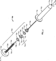
図1を参照すると、眼内レンズ(IOL)を眼に挿入するための装置100は、ボディ部材102を有する。多くの実施形態において、装置100は、プランジャ104も有するものとして説明される。特定の実施形態によれば、装置100は、プランジャ104がボディ部材102内において一方向、すなわち末端方向のみにスライド可能であり、反対の基端方向へはスライドしないように構成されている。加えて、又は、代わりに、装置は、プランジャ104が回転しながら末端方向へ移動可能となるように構成してもよい。この回転は、プランジャ104のスライド移動と連動してもよいし、別個であってもよい。
Referring to FIG. 1, an
図1と図2に示されるような多くの実施形態についてさらに詳細に説明すると、ボディ部材102は、略チューブ状であり、内側貫通室108を形成する内表面106を有する。ボディ部材102はまた、基端の入口110と末端のポート112とを有するものとして説明することもでき、長手方向の軸Aと末端方向Dと基端方向Pとを有する。いくつかの実施形態において、ボディ部材102は、概ね円錐台の形状をした末端部114と、基端の開口部110又はその付近に配置された環状のフランジ116とを有してもよい。
In more detail for many embodiments as shown in FIGS. 1 and 2, the
ある実施形態において、装置100はさらに、眼内レンズを保持するためのカートリッジ(図示せず)を有してもよい。そのような実施形態において、カートリッジは、好ましくは装置100の末端部114付近に取り付けられ、この場合、末端部114は、図1に示す概ね円錐台形状以外の形態を有してもよい。ある実施形態において、術者または他のユーザーへの出荷前に、カートリッジに眼内レンズが予め装填され、且つ/又は、カートリッジが装置100に予め取り付けられてもよい。
In certain embodiments, the
図1と図2を引き続き参照すると、プランジャ104は、多くの実施形態に従って構成できる。例えば、いくつかの実施形態において、プランジャ104は、ロック部材120を備えた、一方向に付勢又は保持する装置118を有する。多くの実施形態において、ロック部材120は保持装置118の周囲に配置される。保持装置118は、特に図2に示されるようにボディ部材102の内部に収容可能である。
With continued reference to FIGS. 1 and 2, the
本明細書において、保持装置118は、別の装置または要素を支持又は保持する何らかの要素または構造を有するものであってもよい。さらに、保持装置は、何かを移動させるように又は何かが外れるのを防止するように機械的に作動するか、或いは、機械的な利点を得るために利用される何らかの装置を有してもよい。本発明の原理によれば、保持装置118は、動かないように固定された装置である必要はなく、必要に応じてボディ部材102内を移動可能又は位置付け可能である。
As used herein, the
さらに詳細に、いくつかの実施形態によれば、保持装置118は、長手方向の第1の方向、例えば、図3の矢印FDで示される末端方向Dへ付勢されると保持装置118がボディ部材102内において矢印Dで示される第1の方向へ移動可能となるように構成される。保持装置118はさらに、長手方向の第1の方向とは反対の第2の方向、例えば、図4の矢印FPで示される基端方向へ付勢されたとき、以下にさらに詳細に説明するようにボディ部材102の内表面106と係合するロック部材120により保持装置118が第2の方向へ移動することが妨げられるか又は実質的に防止されるように構成される。したがって、ロック部材120は、ボディ部材102内において単一の長手方向へ移動できる一方向のロック部材として説明することもできる。
Further in detail, according to some embodiments, the
多くの実施形態によれば、保持装置118は、末端方向Dへ付勢されるとロック部材120がボディ部材102の内表面106にスライド係合するように構成される。これに関連して、ロック部材120は、例えば、連続的に滑らかなOリング、又はリブの付いたOリングのいずれかのOリング等のシール部材で構成される。したがって、ロック部材120と内表面106とのスライド係合は、図5の符号Sで示すようなシール係合でもある。これらのタイプの実施形態において、保持装置118と内表面106とのスライド係合をさらによくするために、ボディ部材102の内表面106は滑らかな面であってもよい。保持又はロックする部材120とボディ部材の内表面とのスライド係合は、保持装置118の滑らかであり、安定し、しっかりした末端側への移動を促進または保証する。
According to many embodiments, the
これにより、保持装置118は、ボディ部材の内部で長手方向に移動するように構成される。特定の実施形態によれば、保持装置118は、ボディ部材の内部でロック部材120がスライド移動するように構成してもよく、そのようなスライド移動は、並進移動(すなわち、実質的に回転を伴わない移動)であってもよいし、回転を伴ってもよい。代わりに、保持装置118は、ロック部材120がボディ部材102の内表面106にスライド可能に係合するように構成してもよく、そのようなスライド可能な係合は、ロック部材120とボディ部材102との接触を含む。さらに、代わりに、保持装置118は、ロック部材120がボディ部材102の内表面106にシール係合するように構成してもよく、そのようなシール係合は、ロック部材120と内表面106との間のシールを含む。
Accordingly, the
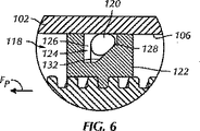
また、図5に示すように、いくつかの実施形態において、保持装置118は、ロック部材120を受けるための環状の座部124を備えたカラー122を有してもよい。座部124は、基端側に配置された通路126と、末端側に配置されたくさび部128とを有する。通路126は、基端側の壁部130を有するように形成される。したがって、カラー122が図5の矢印FDで示されるように末端側へ付勢されると、ロック部材120は、基端側の壁部130に隣接した状態で通路126内に収容される。カラー122が図6の矢印FPで示されるように基端側へ付勢されると、ロック部材120はくさび部128とボディ部材102の内表面106との間へ付勢され、これにより、カラー122、ひいては保持装置118の基端側への移動を妨げるか又は実質的に防止できる。
Also, as shown in FIG. 5, in some embodiments, the
特に図5と図6に示されるように、座部124のくさび部128は、直線状またはアーチ状の傾斜面として説明することができ、その傾斜角度は、好ましくは、内表面106へ向かう外方で、且つ、ボディ部材102の末端部114へ向かう末端側へ傾いている。これにより、カラー122が末端側へ付勢されたとき、図5に示すようにロック部材120が通路126内に収容され、カラー122が基端側へ付勢されたとき、図6に示すようにロック部材120が傾斜面132と内表面106との間に挟まれる。
As shown in particular in FIGS. 5 and 6, the
特定の実施形態と、個別の要素の選択されたパラメータによれば、座部124とロック部材120は、ロック部材120が傾斜面132とボディ部材102の内表面106との間に挟まれたときに、カラー122の基端側への移動が実質的に防止されるように構成してもよい。例えば、多くの実施形態において、ロック部材120は、図1に示すようなOリングであってもよいし、又はそれを含んでもよい。Oリング134は、図6に示すような力に基づき圧縮可能な伸縮性または弾力性のある素材からなる。代わりに、ロック部材120は、例えば、スリット付きOリング、1組の球形または細長いボール、或いは、複数の略円筒状の区分であってもよい。ある実施形態において、ロック部材120は、さらにシールの役割を果たす。
According to certain embodiments and selected parameters of the individual elements, the
例えば、Oリング134と内表面106との間の摩擦係数にもよるが、高レベルの人為的な力を受けても、カラー122は基端方向へは実質的に移動しない。他の実施形態において、カラーを基端方向へ移動させるのに必要なレベルの力は、保持装置118を本質的に破壊し、装置を使用できなくするほどのものである。例えば、その必要な力は、部材にひびを入れたり、プランジャ104との接続を切ったりすることがある。代わりに、Oリング134は、保持装置118が基端面の下で傾くような異なる大きさを有してもよく、これにより、保持装置118がボディ部材102内で留まるようにすることができる。
For example, depending on the coefficient of friction between the O-
多くの実施形態において、プランジャ104はまた、細長い柄138と摘み140を備えたハンドル136を有し、柄138は動作可能に保持装置118に連結される。例えば、図2と図3に示すように、柄138が動作可能に保持装置118に連結されることにより、ハンドル136が長手方向の末端方向Dへ押されると、ハンドル136と保持装置118が長手方向の末端方向Dへ移動する。他の実施形態においては、柄138は、ハンドル136が保持装置118に対して回転可能となるように保持装置118に動作可能に連結されてもよい。
In many embodiments, the
保持装置118の基端方向への移動が妨げられた状態で、柄138は、ハンドル136が図7の矢印Rで示されるように長手方向の軸A周りの第1の方向に回転されたときに保持装置118に対して長手方向の末端方向Dへ移動するように、動作可能に保持装置118に連結されてもよい。さらに、柄138は、ハンドル136が図7の矢印Rで示されるように長手方向の軸A周りの第2の方向へ回転されたときに保持装置118に対して長手方向の基端方向Pへ移動するように、動作可能に保持装置118に連結されてもよい。
The
回転の実施形態において、保持装置118のカラー122は、図1と図5に示すようにねじ切りされた貫通穴142を有し、ハンドル136の柄138は、貫通穴142に係合するために十分な程度の範囲に沿って配置されたねじ山144を有する。したがって、ボディ部材102を通して末端側へハンドル136を長手方向に沿って押すというよりはむしろ、摘み140を操作することによりハンドル136が回転され、これにより、ボディ部材102を通してハンドル136を長手方向に移動させることができる。
In the rotational embodiment, the
この点において、プランジャ104はまた、ハンドル136の柄138の末端部148に動作可能に連結されたインサータ146を有する。インサータ146はまた、Oリングなどのシール部材154を受けるための環状の座部152を備えたベース部150を有する。多くの実施形態において、インサータ146とシール部材154は図2、図3、図4及び図7に示すように、ボディ部材102の内表面106にスライド可能に係合されるように構成されてもよい。さらに、インサータ146は、細長い末端の探針156を有し、探針は、上記と同じ図に示されるようにボディ部材102の末端ポート112を通る状態でスライド可能に収容可能である。
In this regard, the
多くの実施形態において、装置100は、保持装置118がボディ部材102に対して回転するのを防止する構造を有してもよい。例えば、図8と図9に示すように、1又は複数の長手方向の通路148が、ボディ部材102の内表面106に形成され、相補的な突部150(図1参照)が、通路148にスライド係合するためのカラー122に配置されてもよい。これにより、通路148と突部158は、ハンドル136の回転によって生じるいかなるカラー122の回転も防止する。
In many embodiments, the
ボディ部材102において保持装置118のスライド係合を促進するために、カラー122の外径DOは、ボディ部材102の貫通路108の内径DIと略等しくしてもよい。これにより、例えば図5に示すように、カラー122は、ボディ部材102の内表面106にスライド可能に接触する。
In order to facilitate sliding engagement of the holding
保持装置118の他の実施形態が図10、図11及び図12に示され、この実施形態において、ロック部材120は、複数の環状のバッフル(baffle)152を有する。バッフル152は、保持装置118が末端側へ付勢されたときにボディ部材102の内表面にスライド係合し、保持装置118が基端側へ付勢されたときにボディ部材102の内表面106に保持可能に係合するように構成される。
Another embodiment of the holding
図12に示すように、バッフル152は、ボディ部材102の貫通路108の内径DIよりも大きい外径DOを有する(図8参照)。これにより、基端の開口部110を通して貫通路108へ挿入されたとき、バッフル152は図10と図11に示すように基端側へ曲がる。これにより、バッフル152は、保持装置118が末端方向へ移動したとき、スライド可能なロック装置を形成するようにボディ部材102の内表面106に付勢される。代わりに、バッフルは、末端側への移動をさらに促進するために予め曲げられるように組み立ててもよい。ある実施形態において、内表面106は、保持動作を促進するように織り込まれるか又は形成されてもよい。
As shown in FIG. 12, the
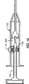
使用の際、図13に示すように、装置100を使用して、末端の探針146がボディ部材102から外へ向かって末端側に移動するように、プランジャ104を長手方向に押すこと、及び/又は、プランジャ104を回転させることによって、眼内レンズが眼154に挿入される。探針146は、公知の方法により眼154の中に配置される。プランジャ104は、上述のような作動および/または操作が継続される。ある実施形態において、装置100はさらに、眼内レンズを含むカートリッジ(図示せず)を有してもよい。そのカートリッジには出荷前に眼内レンズが装填されてもよいし、外科手術中において術者又は術者の助手により眼内レンズが装填されてもよい。カートリッジは好ましくは末端部114の周辺に配置される。
In use, as shown in FIG. 13, the
本発明の上記の典型的な実施形態が多くの代替および変更の根拠を提供することは、当業者に明白である。例えばボディ部材102及び保持装置118について円形の実施形態が図示されているが、装置100の円形または環状でない他の実施形態を使用してもよい。上記及びその他の変更も本発明の範囲内である。したがって、本発明は、上記においてはっきりと明示し、説明した発明に限定されず、添付された請求項の範囲によるものである。
It will be apparent to those skilled in the art that the above exemplary embodiments of the present invention provide a basis for many alternatives and modifications. For example, although circular embodiments are illustrated for the
100:眼内レンズを眼に挿入するための装置、102:ボディ部材、104:プランジャ、106:ボディ部材の内表面、108:貫通路、110:基端の開口部、112:末端のポート、114:ボディ部材の末端部、116:フランジ、118:保持装置、120:ロック部材、122:カラー、124:座部、126:通路、128:くさび部、130:基端側の壁部、132:傾斜面、136:ハンドル、138:柄、140:摘み、142:貫通穴、144:ねじ山、148:通路、156:探針、158:突部。 100: a device for inserting an intraocular lens into the eye, 102: a body member, 104: a plunger, 106: an inner surface of the body member, 108: a through passage, 110: a proximal opening, 112: a distal port, 114: Terminal part of the body member, 116: Flange, 118: Holding device, 120: Lock member, 122: Collar, 124: Seat part, 126: Passage, 128: Wedge part, 130: Wall part on the proximal end side, 132 : Inclined surface, 136: handle, 138: handle, 140: knob, 142: through hole, 144: screw thread, 148: passage, 156: probe, 158: protrusion.
Claims (21)
前記ボディ部材内に収容可能であり、ロック部材を有する保持装置と、を備え、
前記保持装置は、
長手方向の末端方向に付勢されたとき、前記ボディ部材内において末端方向へ移動可能であり、
長手方向において末端方向とは反対の基端方向に付勢されたとき、前記ロック部材が前記ボディ部材の前記内表面に係合することにより、基端方向への移動が実質的に妨げられるように構成され、
前記保持装置は、前記ロック部材を受けるための環状の座部を備えたカラーを含み、
前記座部は、基端側に配置された通路と、末端側に配置されたくさび部と、を含み、
該くさび部は、外側且つ末端側へ向かう角度の傾斜面であり、
前記通路と前記傾斜面とは、前記カラーが末端側へ付勢されたとき前記ロック部材が前記通路に収容され、且つ、前記カラーが基端側へ付勢されたとき前記カラーの基端方向への移動が実質的に妨げられるように前記ロック部材が前記傾斜面と前記ボディ部材の前記内表面との間に挟まれるように構成されている、眼内レンズを眼に挿入するための装置。A body member having an inner surface;
A holding device that can be accommodated in the body member and has a locking member;
The holding device is
When energized in the longitudinal direction of the distal direction and are movable in the distal direction in the body member,
When the lock member is biased in the proximal direction opposite to the distal direction in the longitudinal direction, the lock member is engaged with the inner surface of the body member so that the movement in the proximal direction is substantially prevented. Composed of
The holding device includes a collar having an annular seat for receiving the locking member;
The seat portion includes a passage disposed on the proximal end side, and a wedge portion disposed on the distal end side,
The wedge portion is an inclined surface having an angle toward the outer side and the distal side,
The passage and the inclined surface are arranged so that the lock member is accommodated in the passage when the collar is biased to the distal side, and the proximal direction of the collar when the collar is biased to the proximal side An apparatus for inserting an intraocular lens into the eye, wherein the locking member is configured to be sandwiched between the inclined surface and the inner surface of the body member such that movement to the eye is substantially impeded .
前記ボディ部材内にスライド可能に収容可能であり、外側且つ末端側へ向かう角度の傾斜面と、該傾斜面よりも基端側に配置された通路とを備えた環状の座部を有するカラーと、
前記カラーが末端側に付勢されたときに前記通路に収容され、且つ、前記カラーが基端側に付勢されたときに前記座部の前記傾斜面と前記ボディ部材の前記内表面との間に挟まれるように、前記カラーの前記座部に収容可能なOリングと、
前記カラーに動作可能に連結された細長いハンドルと、を備えた、眼内レンズを眼に挿入するための装置。A tubular body member having an inner surface and defined by a longitudinal axis having a distal end and a proximal end;
A collar having an annular seat that is slidably accommodated in the body member, and includes an inclined surface that is inclined outward and toward the distal side, and a passage that is disposed on the proximal side of the inclined surface. ,
The collar is accommodated in the passage when biased toward the distal end, and the inclined surface of the seat portion and the inner surface of the body member when the collar is biased toward the proximal end. An O-ring that can be accommodated in the seat portion of the collar so as to be sandwiched between them;
An apparatus for inserting an intraocular lens into the eye, comprising an elongated handle operably coupled to the collar.
Applications Claiming Priority (3)
| Application Number | Priority Date | Filing Date | Title |
|---|---|---|---|
| US11/107,057 | 2005-04-15 | ||
| US11/107,057 US7740636B2 (en) | 2005-04-15 | 2005-04-15 | Multi-action device for inserting an intraocular lens into an eye |
| PCT/US2006/013878 WO2006113357A2 (en) | 2005-04-15 | 2006-04-12 | Multi-action device for inserting an intraocular lens into an eye |
Publications (3)
| Publication Number | Publication Date |
|---|---|
| JP2008536569A JP2008536569A (en) | 2008-09-11 |
| JP2008536569A5 JP2008536569A5 (en) | 2009-05-14 |
| JP4871353B2 true JP4871353B2 (en) | 2012-02-08 |
Family
ID=36948090
Family Applications (1)
| Application Number | Title | Priority Date | Filing Date |
|---|---|---|---|
| JP2008506693A Active JP4871353B2 (en) | 2005-04-15 | 2006-04-12 | Multi-action device for inserting an intraocular lens into the eye |
Country Status (9)
| Country | Link |
|---|---|
| US (2) | US7740636B2 (en) |
| EP (1) | EP1871315B1 (en) |
| JP (1) | JP4871353B2 (en) |
| AT (1) | ATE471134T1 (en) |
| AU (1) | AU2006236695B2 (en) |
| BR (1) | BRPI0609461B8 (en) |
| CA (1) | CA2604766C (en) |
| DE (1) | DE602006014952D1 (en) |
| WO (1) | WO2006113357A2 (en) |
Families Citing this family (53)
| Publication number | Priority date | Publication date | Assignee | Title |
|---|---|---|---|---|
| US8545512B2 (en) | 2005-01-26 | 2013-10-01 | Hoya Corporation | Intraocular lens insertion device |
| US8435289B2 (en) * | 2005-02-11 | 2013-05-07 | Abbott Medical Optics Inc. | Rapid exchange IOL insertion apparatus and methods of using |
| JP4836046B2 (en) | 2005-02-24 | 2011-12-14 | Hoya株式会社 | Intraocular lens insertion device |
| US8574239B2 (en) | 2005-09-28 | 2013-11-05 | Hoya Corporation | Intraocular lens insertion device |
| JP4877643B2 (en) | 2005-12-08 | 2012-02-15 | Hoya株式会社 | Intraocular lens insertion device |
| JP4648859B2 (en) * | 2006-03-15 | 2011-03-09 | スター・ジャパン株式会社 | Intraocular lens insertion device and intraocular lens insertion system |
| US8460375B2 (en) | 2006-08-14 | 2013-06-11 | Novartis Ag | Lens delivery system |
| US20080200921A1 (en) * | 2007-02-15 | 2008-08-21 | Downer David A | Lens Delivery System |
| US9522061B2 (en) | 2007-02-15 | 2016-12-20 | Novartis Ag | Lens delivery system |
| EP2161005B1 (en) | 2007-05-30 | 2016-12-28 | Hoya Corporation | Intraocular lens inserting tool |
| JP5086713B2 (en) | 2007-07-11 | 2012-11-28 | Hoya株式会社 | Intraocular lens insertion device |
| GB0714005D0 (en) * | 2007-07-18 | 2007-08-29 | Rayner Intraocular Lenses Ltd | Device for inserting an intraocular lens into a eye |
| US8105332B2 (en) * | 2007-10-30 | 2012-01-31 | Novartis Ag | Lens delivery system |
| AU2009212211B2 (en) | 2008-02-07 | 2013-03-14 | Alcon Inc. | Lens delivery system cartridge |
| JP5254669B2 (en) | 2008-06-05 | 2013-08-07 | Hoya株式会社 | Intraocular lens insertion device and cartridge |
| JP5470753B2 (en) | 2008-06-17 | 2014-04-16 | Hoya株式会社 | Intraocular lens insertion device |
| JP5323420B2 (en) | 2008-08-21 | 2013-10-23 | Hoya株式会社 | Intraocular lens insertion device |
| CH699588A1 (en) * | 2008-09-22 | 2010-03-31 | Medicel Ag | Cartridge for an intraocular lens injector system and for it. |
| US20100087832A1 (en) * | 2008-10-03 | 2010-04-08 | Seyboth William J | Intraocular lens injector |
| US8808308B2 (en) | 2008-10-13 | 2014-08-19 | Alcon Research, Ltd. | Automated intraocular lens injector device |
| US8801780B2 (en) | 2008-10-13 | 2014-08-12 | Alcon Research, Ltd. | Plunger tip coupling device for intraocular lens injector |
| US8308736B2 (en) | 2008-10-13 | 2012-11-13 | Alcon Research, Ltd. | Automated intraocular lens injector device |
| CN102307543B (en) | 2009-01-07 | 2015-10-21 | Hoya株式会社 | Intraocular lens inserting instrument |
| NZ594436A (en) * | 2009-02-11 | 2013-09-27 | Alcon Res Ltd | Automated intraocular lens injector device |
| US9326847B2 (en) | 2010-04-08 | 2016-05-03 | Hoya Corporation | Ocular implant insertion apparatus and methods |
| US8308799B2 (en) | 2010-04-20 | 2012-11-13 | Alcon Research, Ltd. | Modular intraocular lens injector device |
| JP5511530B2 (en) | 2010-06-10 | 2014-06-04 | Hoya株式会社 | Intraocular lens insertion device |
| US8579969B2 (en) | 2010-07-25 | 2013-11-12 | Alcon Research, Ltd. | Dual mode automated intraocular lens injector device |
| US8535268B2 (en) | 2010-12-22 | 2013-09-17 | Alcon Research, Ltd. | Device for at least one of injection or aspiration |
| EP2567674B1 (en) * | 2011-09-07 | 2015-05-06 | SDI Surgical Device International GmbH | Modular intraocular lens injector |
| US9510945B2 (en) * | 2011-12-20 | 2016-12-06 | Boston Scientific Scimed Inc. | Medical device handle |
| US8657835B2 (en) | 2012-01-27 | 2014-02-25 | Alcon Research, Ltd. | Automated intraocular lens injector device |
| GB2501109B (en) * | 2012-04-12 | 2014-04-23 | Duckworth & Kent Ltd | Actuator for device for delivery of ophthalmic lenses |
| US9463089B2 (en) | 2012-05-21 | 2016-10-11 | Novartis Ag | Plunger system for intraocular lens surgery |
| AU2013271703B2 (en) | 2012-06-04 | 2017-05-11 | Alcon Inc. | Intraocular lens inserter |
| EP3766455A1 (en) | 2012-06-12 | 2021-01-20 | Alcon Inc. | Intraocular gas injector |
| JP6071349B2 (en) * | 2012-09-05 | 2017-02-01 | 興和株式会社 | Intraocular lens insertion device and auxiliary device for insertion device |
| KR101396194B1 (en) * | 2012-10-05 | 2014-05-19 | 주식회사 세종메디칼 | Intraocular lens injecting apparatus |
| GB2517921B (en) | 2013-09-04 | 2015-12-16 | Duckworth & Kent Ltd | Device for use in a delivery of ophthalmic lenses |
| US10010408B2 (en) | 2014-04-04 | 2018-07-03 | Alcon Pharmaceuticals, Ltd. | Intraocular lens inserter |
| WO2015168009A1 (en) * | 2014-04-27 | 2015-11-05 | Ravi Nallakrishnan | Apparatus for injecting an intraocular lens |
| US10588780B2 (en) | 2015-03-04 | 2020-03-17 | Alcon Inc. | Intraocular lens injector |
| US10779940B2 (en) | 2015-09-03 | 2020-09-22 | Boston Scientific Scimed, Inc. | Medical device handle |
| CN107920891A (en) | 2015-09-16 | 2018-04-17 | Hoya株式会社 | Intraocular lens inserting instrument |
| JP6646987B2 (en) | 2015-09-16 | 2020-02-14 | Hoya株式会社 | Intraocular lens insertion device |
| US10172706B2 (en) | 2015-10-31 | 2019-01-08 | Novartis Ag | Intraocular lens inserter |
| AU2016354549B2 (en) * | 2015-11-13 | 2020-11-26 | Johnson & Johnson Surgical Vision, Inc. | Intraocular lens insertion device |
| US10583005B2 (en) | 2016-05-13 | 2020-03-10 | Boston Scientific Scimed, Inc. | Medical device handle |
| KR102431211B1 (en) * | 2016-06-28 | 2022-08-09 | 호야 가부시키가이샤 | Intraocular lens injector |
| US10568735B2 (en) | 2017-01-13 | 2020-02-25 | Alcon Inc. | Intraocular lens injector |
| US11000367B2 (en) | 2017-01-13 | 2021-05-11 | Alcon Inc. | Intraocular lens injector |
| US10849739B2 (en) * | 2018-08-02 | 2020-12-01 | Carl Zeiss Meditec Ag | Ophthalmosurgical injector system |
| US11224537B2 (en) | 2018-10-19 | 2022-01-18 | Alcon Inc. | Intraocular gas injector |
Citations (4)
| Publication number | Priority date | Publication date | Assignee | Title |
|---|---|---|---|---|
| JPH06190040A (en) * | 1992-10-20 | 1994-07-12 | Eli Lilly & Co | Retrograde prevention device in subcutaneous syringe |
| JP2004113610A (en) * | 2002-09-27 | 2004-04-15 | Nidek Co Ltd | Intraocular lens inserting implement |
| WO2004105648A1 (en) * | 2003-05-27 | 2004-12-09 | Hoya Corporation | Injector |
| WO2005011782A1 (en) * | 2003-07-30 | 2005-02-10 | Becton Dickinson And Company | Syringe assembly having disabling mechanism |
Family Cites Families (52)
| Publication number | Priority date | Publication date | Assignee | Title |
|---|---|---|---|---|
| US2216354A (en) * | 1939-02-25 | 1940-10-01 | Delmer I Pletcher | Dosage regulator and control wedge for hypodermic syringes |
| US3452740A (en) * | 1966-05-31 | 1969-07-01 | Us Catheter & Instr Corp | Spring guide manipulator |
| US4444335A (en) * | 1981-09-14 | 1984-04-24 | Merck & Co., Inc. | Delivery of adjustable quantities of materials |
| JPS6130699U (en) * | 1984-07-26 | 1986-02-24 | 三菱鉛筆株式会社 | syringe |
| US4919130A (en) * | 1986-11-07 | 1990-04-24 | Nestle S.A. | Tool for inserting compressible intraocular lenses into the eye and method |
| US4934363A (en) * | 1987-12-15 | 1990-06-19 | Iolab Corporation | Lens insertion instrument |
| DE8804656U1 (en) | 1988-04-08 | 1988-08-04 | Bader, Mohandes, 2350 Neumuenster, De | |
| US4862885A (en) * | 1988-05-25 | 1989-09-05 | Cumming J Stuart | Instrument for inserting a deformable intraocular lens into the eye |
| FR2634650B1 (en) * | 1988-08-01 | 1990-11-02 | Labouze Joseph | NON REUSABLE SYRINGE |
| CA2000287A1 (en) | 1988-10-07 | 1990-04-07 | David C. Buboltz | Intraocular lens insertion instrument |
| US4906231A (en) * | 1988-10-14 | 1990-03-06 | Young J Winslow | Single-use fillable syringe |
| US5021047A (en) * | 1989-08-29 | 1991-06-04 | Movern John B | Restricted use hypodermic syringe |
| DE3932109A1 (en) * | 1989-09-26 | 1991-04-11 | Sarstedt Walter Geraete | BLOOD COLLECTION DEVICE |
| ES2021249A6 (en) * | 1990-07-25 | 1991-10-16 | Serrano Gonzalez Antonio | Single use syringe. |
| US5259840A (en) * | 1991-09-03 | 1993-11-09 | Boris Craig R | Locking syringe |
| US5161838A (en) * | 1991-11-19 | 1992-11-10 | The Highfield Mfg. Company | Locking assembly |
| US5195973A (en) * | 1992-02-21 | 1993-03-23 | Novick Howard J | Self-destructing disposable safety syringe system with piston and plunger joined by weak attachment sealant |
| US5807400A (en) | 1992-09-30 | 1998-09-15 | Staar Surgical Company, Inc. | Deformable intraocular lens insertion system |
| US5941886A (en) * | 1992-09-30 | 1999-08-24 | Staar Surgical Company, Inc. | Hingeless lens cartridges for insertion of deformable intraocular lens |
| DE69331807T2 (en) * | 1992-09-30 | 2002-09-26 | Vladimir Feingold | INTRAOCULAR LENS INSERTION SYSTEM |
| US5380295A (en) * | 1992-12-14 | 1995-01-10 | Mallinckrodt Medical, Inc. | Delivery apparatus with mechanism preventing rearward movement of a piston disposed therein |
| US5653715A (en) * | 1993-03-09 | 1997-08-05 | Chiron Vision Corporation | Apparatus for preparing an intraocular lens for insertion |
| US5344409A (en) * | 1993-06-14 | 1994-09-06 | Genesis Industries Inc. | Syringe latch |
| US5468246A (en) * | 1993-07-02 | 1995-11-21 | Iovision, Inc. | Intraocular lens injector |
| US5578042A (en) * | 1994-03-14 | 1996-11-26 | Cumming; J. Stuart | Ophthalmic kit and method for lens insertion |
| US5453092A (en) * | 1994-07-05 | 1995-09-26 | Merriman; Grant B. | Locking system for hypodermic syringes |
| CA2173609C (en) * | 1994-08-05 | 2006-06-20 | Dennis Alexander Figueroa | Device for inserting a flexible intraocular lens |
| US5637092A (en) * | 1995-01-30 | 1997-06-10 | Shaw; Thomas J. | Syringe plunger locking assembly |
| US5512054A (en) * | 1995-05-16 | 1996-04-30 | American Medical Systems, Inc. | Dual action syringe |
| US5683116A (en) * | 1995-10-24 | 1997-11-04 | Ameron International Corporation | O-ring push-pull pipe joint |
| US5715954A (en) * | 1996-01-16 | 1998-02-10 | Zaremba; George Julian | Removable display attachment for vertical rigid cylindrical supports |
| US5733261A (en) * | 1996-03-08 | 1998-03-31 | Obong; Ekoi Edet | Single use locking syringe |
| US6083230A (en) * | 1997-07-30 | 2000-07-04 | Allergan | Method for making IOL insertion apparatus |
| US6503275B1 (en) | 1996-11-15 | 2003-01-07 | Medevec Licensing, B.V. | Ophthalmic lens insertion instrument and package |
| US5891153A (en) * | 1997-12-23 | 1999-04-06 | Peterson; Randy | Auger nucleus extracted for cataracts |
| US5931671A (en) * | 1998-01-28 | 1999-08-03 | Hoffman; Elliott S. | Dental saliva ejector tube assembly |
| US5921989A (en) * | 1998-02-12 | 1999-07-13 | Allergan | Lens protector for intraocular lens inserter |
| US6143021A (en) * | 1998-07-10 | 2000-11-07 | American Medical Systems, Inc. | Stent placement instrument and method of assembly |
| US6368303B1 (en) * | 1999-10-15 | 2002-04-09 | Becton, Dickinson And Company | Retracting needle syringe |
| US6251114B1 (en) * | 1999-10-29 | 2001-06-26 | Allergan Sales, Inc. | Rotatable IOL insertion apparatus and method for using same |
| US6425885B1 (en) * | 1999-12-20 | 2002-07-30 | Ultradent Products, Inc. | Hydraulic syringe |
| US6558357B1 (en) * | 2000-08-30 | 2003-05-06 | Becton Dickinson And Company | Hypodermic syringe with selectively retractable needle |
| ATE442106T1 (en) * | 2001-08-23 | 2009-09-15 | Meyer & Co Ag Anton | DEVICE FOR INSERTING A LENS INTO AN EYE |
| US6866669B2 (en) * | 2001-10-12 | 2005-03-15 | Cordis Corporation | Locking handle deployment mechanism for medical device and method |
| US6939352B2 (en) * | 2001-10-12 | 2005-09-06 | Cordis Corporation | Handle deployment mechanism for medical device and method |
| US6732436B2 (en) * | 2002-01-10 | 2004-05-11 | Mentor Group Llc | Folding tool |
| JP3791421B2 (en) * | 2002-01-23 | 2006-06-28 | キヤノンスター株式会社 | Intraocular lens insertion device |
| US6923815B2 (en) | 2002-05-14 | 2005-08-02 | Advanced Medical Optics, Inc. | Intraocular lens insertion apparatus |
| US20040059343A1 (en) * | 2002-09-25 | 2004-03-25 | Kevin Shearer | Novel enhanced system for intraocular lens insertion |
| JP2004173805A (en) | 2002-11-26 | 2004-06-24 | Takashima Sangyo Kk | Intraocular lens insertion instrument |
| US7156854B2 (en) | 2003-05-28 | 2007-01-02 | Alcon, Inc. | Lens delivery system |
| US7210398B2 (en) * | 2004-02-18 | 2007-05-01 | Bal Seal Engineering Co., Inc. | Cover seals with latching locking features |
-
2005
- 2005-04-15 US US11/107,057 patent/US7740636B2/en active Active
-
2006
- 2006-04-12 EP EP06740931A patent/EP1871315B1/en active Active
- 2006-04-12 DE DE602006014952T patent/DE602006014952D1/en active Active
- 2006-04-12 AU AU2006236695A patent/AU2006236695B2/en not_active Ceased
- 2006-04-12 WO PCT/US2006/013878 patent/WO2006113357A2/en active Application Filing
- 2006-04-12 CA CA2604766A patent/CA2604766C/en active Active
- 2006-04-12 JP JP2008506693A patent/JP4871353B2/en active Active
- 2006-04-12 AT AT06740931T patent/ATE471134T1/en not_active IP Right Cessation
- 2006-04-12 BR BRPI0609461A patent/BRPI0609461B8/en not_active IP Right Cessation
-
2010
- 2010-05-04 US US12/773,288 patent/US8926628B2/en active Active
Patent Citations (4)
| Publication number | Priority date | Publication date | Assignee | Title |
|---|---|---|---|---|
| JPH06190040A (en) * | 1992-10-20 | 1994-07-12 | Eli Lilly & Co | Retrograde prevention device in subcutaneous syringe |
| JP2004113610A (en) * | 2002-09-27 | 2004-04-15 | Nidek Co Ltd | Intraocular lens inserting implement |
| WO2004105648A1 (en) * | 2003-05-27 | 2004-12-09 | Hoya Corporation | Injector |
| WO2005011782A1 (en) * | 2003-07-30 | 2005-02-10 | Becton Dickinson And Company | Syringe assembly having disabling mechanism |
Also Published As
| Publication number | Publication date |
|---|---|
| US20100217274A1 (en) | 2010-08-26 |
| AU2006236695B2 (en) | 2012-01-19 |
| CA2604766C (en) | 2015-01-06 |
| CA2604766A1 (en) | 2006-10-26 |
| BRPI0609461A2 (en) | 2011-10-11 |
| BRPI0609461B1 (en) | 2018-06-26 |
| AU2006236695A1 (en) | 2006-10-26 |
| US20060235429A1 (en) | 2006-10-19 |
| BRPI0609461B8 (en) | 2021-06-22 |
| WO2006113357A3 (en) | 2006-12-14 |
| JP2008536569A (en) | 2008-09-11 |
| US7740636B2 (en) | 2010-06-22 |
| EP1871315A2 (en) | 2008-01-02 |
| US8926628B2 (en) | 2015-01-06 |
| DE602006014952D1 (en) | 2010-07-29 |
| WO2006113357A2 (en) | 2006-10-26 |
| EP1871315B1 (en) | 2010-06-16 |
| ATE471134T1 (en) | 2010-07-15 |
Similar Documents
| Publication | Publication Date | Title |
|---|---|---|
| JP4871353B2 (en) | Multi-action device for inserting an intraocular lens into the eye | |
| JP4791528B2 (en) | Method and apparatus for inserting an intraocular lens into the eye | |
| US9326847B2 (en) | Ocular implant insertion apparatus and methods | |
| JP4703929B2 (en) | Rotatable IOL insertion device and method of use thereof | |
| US20040059343A1 (en) | Novel enhanced system for intraocular lens insertion | |
| US6267768B1 (en) | Lens protector for intraocular lens inserter | |
| US8657876B2 (en) | Methods and apparatus for inserting an intraocular lens into an eye | |
| US20060235430A1 (en) | Corneal implant injector assembly and methods of use | |
| JP4955573B2 (en) | Pre-mounted intraocular lens introduction device and method | |
| US20030088253A1 (en) | Dual action ophthalmic implant extractor | |
| JP5085119B2 (en) | Spring bias injector for intraocular lens | |
| US20030139749A1 (en) | Insertion device for deformable intraocular lens | |
| US20050015145A1 (en) | Intraocular lens system | |
| TW200524569A (en) | Improved IOL inserter plunger and body interface | |
| SG185738A1 (en) | Ocular implant insertion apparatus and methods | |
| KR20150129304A (en) | Systems and processes for inserting an intraocular lens | |
| CN108472128A (en) | Improved accommodating intraocular lens | |
| JP2009082689A (en) | Intraocular lens | |
| US8888845B2 (en) | Method of inserting an intraocular lens |
Legal Events
| Date | Code | Title | Description |
|---|---|---|---|
| A521 | Request for written amendment filed |
Free format text: JAPANESE INTERMEDIATE CODE: A523 Effective date: 20090326 |
|
| A621 | Written request for application examination |
Free format text: JAPANESE INTERMEDIATE CODE: A621 Effective date: 20090326 |
|
| A131 | Notification of reasons for refusal |
Free format text: JAPANESE INTERMEDIATE CODE: A131 Effective date: 20101116 |
|
| A977 | Report on retrieval |
Free format text: JAPANESE INTERMEDIATE CODE: A971007 Effective date: 20101118 |
|
| A131 | Notification of reasons for refusal |
Free format text: JAPANESE INTERMEDIATE CODE: A131 Effective date: 20110705 |
|
| A521 | Request for written amendment filed |
Free format text: JAPANESE INTERMEDIATE CODE: A523 Effective date: 20111003 |
|
| TRDD | Decision of grant or rejection written | ||
| A01 | Written decision to grant a patent or to grant a registration (utility model) |
Free format text: JAPANESE INTERMEDIATE CODE: A01 Effective date: 20111101 |
|
| A01 | Written decision to grant a patent or to grant a registration (utility model) |
Free format text: JAPANESE INTERMEDIATE CODE: A01 |
|
| A61 | First payment of annual fees (during grant procedure) |
Free format text: JAPANESE INTERMEDIATE CODE: A61 Effective date: 20111118 |
|
| R150 | Certificate of patent or registration of utility model |
Ref document number: 4871353 Country of ref document: JP Free format text: JAPANESE INTERMEDIATE CODE: R150 Free format text: JAPANESE INTERMEDIATE CODE: R150 |
|
| FPAY | Renewal fee payment (event date is renewal date of database) |
Free format text: PAYMENT UNTIL: 20141125 Year of fee payment: 3 |
|
| R250 | Receipt of annual fees |
Free format text: JAPANESE INTERMEDIATE CODE: R250 |
|
| R250 | Receipt of annual fees |
Free format text: JAPANESE INTERMEDIATE CODE: R250 |
|
| R250 | Receipt of annual fees |
Free format text: JAPANESE INTERMEDIATE CODE: R250 |
|
| R250 | Receipt of annual fees |
Free format text: JAPANESE INTERMEDIATE CODE: R250 |
|
| R250 | Receipt of annual fees |
Free format text: JAPANESE INTERMEDIATE CODE: R250 |
|
| R250 | Receipt of annual fees |
Free format text: JAPANESE INTERMEDIATE CODE: R250 |
|
| R250 | Receipt of annual fees |
Free format text: JAPANESE INTERMEDIATE CODE: R250 |
|
| R250 | Receipt of annual fees |
Free format text: JAPANESE INTERMEDIATE CODE: R250 |
|
| R250 | Receipt of annual fees |
Free format text: JAPANESE INTERMEDIATE CODE: R250 |