JP4869073B2 - Molded product manufacturing method - Google Patents
Molded product manufacturing method Download PDFInfo
- Publication number
- JP4869073B2 JP4869073B2 JP2006540376A JP2006540376A JP4869073B2 JP 4869073 B2 JP4869073 B2 JP 4869073B2 JP 2006540376 A JP2006540376 A JP 2006540376A JP 2006540376 A JP2006540376 A JP 2006540376A JP 4869073 B2 JP4869073 B2 JP 4869073B2
- Authority
- JP
- Japan
- Prior art keywords
- blank
- joint
- molded product
- milling
- membrane
- Prior art date
- Legal status (The legal status is an assumption and is not a legal conclusion. Google has not performed a legal analysis and makes no representation as to the accuracy of the status listed.)
- Expired - Fee Related
Links
Images


Classifications
-
- A—HUMAN NECESSITIES
- A61—MEDICAL OR VETERINARY SCIENCE; HYGIENE
- A61C—DENTISTRY; APPARATUS OR METHODS FOR ORAL OR DENTAL HYGIENE
- A61C13/00—Dental prostheses; Making same
- A61C13/0003—Making bridge-work, inlays, implants or the like
-
- A—HUMAN NECESSITIES
- A61—MEDICAL OR VETERINARY SCIENCE; HYGIENE
- A61C—DENTISTRY; APPARATUS OR METHODS FOR ORAL OR DENTAL HYGIENE
- A61C13/00—Dental prostheses; Making same
- A61C13/0003—Making bridge-work, inlays, implants or the like
- A61C13/0022—Blanks or green, unfinished dental restoration parts
Abstract
Description
本発明は、成形品を切削加工によりブランクから作出し、成形品と残りのブランクの間の継手を切断することによって加工を終了する、成形品特に歯科用品、例えばキャップ又はブリッジフレームの作製方法に関する。 The present invention relates to a method for producing a molded article, in particular a dental article, for example a cap or a bridge frame, wherein the molded article is produced from a blank by cutting and the machining is terminated by cutting a joint between the molded article and the remaining blank. .
人工歯冠又は架工義歯(ブリッジ)の在来の作製方法では、石こう型取りにより口内の状況の陽性モデルを作るために、歯科的準備の後に顎の型を作成する。当該のいわゆる種型(マスターモデル)で基本骨格をろう又はプラスチックで型取りし、次に例えばろう原型法又はならいフライス加工により基本骨格の型を金属で仕上げ、場合によっては陶材を焼き付けてかぶせる。 In the conventional method of making an artificial crown or bridge denture, a jaw mold is created after dental preparation in order to create a positive model of the situation in the mouth by gypsum casting. Mold the basic skeleton with wax or plastic with the so-called seed mold (master model), then finish the basic skeleton with metal, for example by brazing or by milling, and in some cases baked with ceramics .
歯冠アンレー(onlays)の作製方法が欧州特許公開EP−A−0389461で明らかである。その場合、まず充填すべき歯髄腔の型が、次に圧縮成形又は予備焼結されたブランクからならいフライス加工により本体が作られ、アンレーの作製のためにこれを最終密度に焼結する。ところが歯冠及び架工義歯とアンレーは別の製品であり、歯科医学的適応症が異なる。即ちアンレーは腔にはめ込まれ、幾何学的形状については常に凹形に成形される。これに対して歯冠又は架工義歯は歯根の上に嵌着され、キャップの形状を有する。このため技術的に扱いにくい、薄くなった周縁部が生じる。 The preparation of crown onlays is evident in European patent publication EP-A-0389461. In that case, the mold of the pulp cavity to be filled is first made into a body by subsequent milling from a compacted or pre-sintered blank, which is sintered to the final density for the production of the onlay. However, dental crowns, bridge dentures and onlays are different products and have different dentistry indications. In other words, the onlay is fitted in the cavity, and the geometric shape is always formed in a concave shape. On the other hand, the crown or bridge denture is fitted on the root and has the shape of a cap. This results in a thinner edge that is technically difficult to handle.
少なくとも1個のあらかじめ準備した歯根の上に嵌着できる義歯を、圧縮成形した微細なセラミック粉末で作製する方法が国際特許公開WO−A−199947065により周知である。その場合、患者の口内の幾何学的状況を走査してデジタル化し、焼結収縮を正確に補償する倍率だけデータをすべての方向に線形に増加することにより、収縮を考慮して、生物学的に適合する材料からなる全セラミック基本骨格の内面を計算し、その上でブランクから材料を削除して内面及び外面を有する基本骨格を作出する。 A method for producing dentures that can be fitted on at least one pre-prepared root with compression-molded fine ceramic powder is known from International Patent Publication No. WO-A-199947065. In that case, the geometrical condition in the patient's mouth is scanned and digitized, and the data is linearly increased in all directions by a factor that accurately compensates for the sintering shrinkage, taking into account the shrinkage and biological The inner surface of the entire ceramic basic skeleton made of a material conforming to the above is calculated, and then the material is removed from the blank to create a basic skeleton having an inner surface and an outer surface.
この種の作製方法では、切削加工即ちフライス削り又は研削される成形体の外側側面にたいていピン付けを含み、その際、歯科用品のピン付けは頬側又は舌側で、まれに隣接側で行われる。加工時に成形体はピン付けによって保持され、終了後におおまかに切り取り、当該の区域の肉厚が残余の成形体の肉厚、即ち歯科用品の場合はキャップ又はフレームの肉厚をほぼ有するように、手加工を行う。軟質の材料の場合は、再加工は破壊の大きな危険を伴うが、これに対して硬質の材料では大きな時間消費と工具費が必要である。また再加工の際に望ましい肉厚を下回る危険がある。 This kind of production method usually includes pinning on the outer side of the shaped body to be machined or milled or ground, with the pinning of the dental article being performed on the buccal or lingual side, and rarely on the adjacent side. Is called. During processing, the molded body is held by pinning and is roughly cut off after completion so that the thickness of the area in question is approximately the thickness of the remaining molded body, i.e. in the case of dental supplies, the thickness of the cap or frame. Perform hand processing. In the case of soft materials, rework involves a great risk of breakage, whereas hard materials require significant time and tool costs. There is also a risk of less than the desired wall thickness during rework.
国際特許公開WO−A−200245614によれば、例えば架工義歯をセラミックブランクからフライス工具によって作製する。架工義歯は保持ウエブによってブランクの残りの残片と結合されている。 According to International Patent Publication WO-A-200245614, for example, a bridge denture is produced from a ceramic blank by a milling tool. The bridge denture is joined to the remaining blank pieces by a holding web.
歯科技工部材、例えば歯冠の作製方法で、ブランクの一部の区域が常に埋込みコンパウンドの中に固定され、埋込みコンパウンドによって覆われない区域を切削加工する(ドイツ特許公開DE−A−19930564)。 In a method for producing dental technician parts, for example crowns, a part of the blank is always fixed in the embedding compound and the area not covered by the embedding compound is cut (DE-A-19930564).
歯科成形品の作製のための代替法は、外側ピン付けの代わりに、除去可能な台座を設け、加工される成形体をこの台座によって固定する。 An alternative method for the production of dental moldings is to provide a removable pedestal instead of external pinning, and the molded body to be processed is secured by this pedestal.
いわゆる浸漬法でもピン付けは不要である。その場合、歯根の型をセラミック・スリップに浸漬することによって、歯根に対して外側フライス加工に耐える付着が作り出される。ところがスリップ・セラミックの低い強度並びに材料のコンシステンシー及び貯蔵の問題が欠点である。 Pinning is not necessary even in the so-called immersion method. In that case, dipping the root mold into a ceramic slip creates an adhesion to the root that will resist outer milling. However, the low strength of slip ceramics as well as material consistency and storage problems are disadvantages.
本発明の課題は、成形品特に歯科用品、例えばキャップ又はブリッジフレームの作製のためのブランクの精密な加工が可能であり、費用のかかる又は危険を伴う再加工が必要でないように、前述の種類の方法を改良することにある。また成形品の加工の後にこれを簡単に取り外すことを可能とすることも本発明の課題である。 The problem of the present invention is that the above-mentioned types are provided so that precise processing of molded articles, in particular blanks for the production of dental articles, for example caps or bridge frames, is possible and no expensive or dangerous rework is necessary. It is to improve the method. It is also an object of the present invention to enable easy removal of the molded product after processing.
上記の課題の解決のために、本発明はおおむね次のように構成する。即ち成形体の外側及び内側輪郭が完成したとき、成形体は円周状のウエブ又は貫通穴を有する膜状継手の形の継手によってブランクと引続き結合されており、続いて継手を切断することによって、成形品をブランクから作出するのである。 In order to solve the above problems, the present invention is generally configured as follows. That is, when the outer and inner contours of the molded body are completed, the molded body is continuously joined to the blank by a joint in the form of a membrane-like joint with a circumferential web or through-hole, and then by cutting the joint. The molded product is made from a blank.
換言すれば、成形体の外側及び内側輪郭が完成したとき、成形体は少なくとも1個の区域的に周囲に延びるウエブ状又は膜状の継手で引続きブランクと結合されており、続いてこれを切断することによって、ブランクから成形品を作出するのである。 In other words, when the outer and inner contours of the molded body are completed, the molded body is still joined to the blank with a web-like or membrane-like joint extending around at least one section and subsequently cut. By doing so, a molded product is produced from the blank.
継手が円周状のウエブであるならば、特に切断は環状即ち円周状のフライス削りによって行われる。その場合、円周状のウエブが歯科用品の成形品の外縁に沿って延びるように、成形品を加工すべきである。両側、即ち頬側及び舌側を加工するときは、円周状のウエブは原則としてキャップの大部分の外周区域で通常、周縁部又はその近傍にある。 If the joint is a circumferential web, in particular the cutting is performed by annular or circumferential milling. In that case, the molding should be processed so that the circumferential web extends along the outer edge of the dental article molding. When machining both sides, i.e. the buccal and lingual sides, the circumferential web is as a rule in the most peripheral area of the cap, usually at or near the periphery.
本発明に基づき、例えば予備焼結又は高密度焼結したセラミック半成品から内側及び外側輪郭の特に荒加工及び仕上加工により加工を行い、環状エッジとも呼ばれる円周状のウエブを除去することにより成形体の外側加工が終了し、こうしてその後の再加工が原則として不要にし、こうして成形品を切削加工することを提案する。 In accordance with the present invention, for example, by forming a pre-sintered or high-density sintered ceramic semi-finished product, particularly by roughing and finishing the inner and outer contours, and removing a circumferential web, also called an annular edge, Thus, it is proposed that the outer machining is finished and thus no further reworking is required in principle , and thus the molded product is cut.
代案として、外側及び内側輪郭が完成した成形品は円周状の膜状継手によって引続きブランクと結合されており、膜状継手は貫通穴を有し、即ち穴あけされており、次に例えば手で力を働かせることにより、又は工具例えばメスを使用することによって膜を切断し、成形品をブランクから取り外す。次に保持膜の残片を除去するために、僅かな再加工しか必要でない。 As an alternative, the molded product with the outer and inner contours being completed is still connected to the blank by means of a circumferential membrane joint, which has a through-hole, i.e. perforated, and then for example by hand. The membrane is cut by applying force or by using a tool such as a knife and the molded article is removed from the blank. Next, only a slight rework is required to remove the remnants of the retaining film.
膜状継手を切断する前のその厚さは、とりわけ50μmないし500μmとする。この点に関する寸法設定によって、ブランクから外すときに成形品が損傷しないことが保証される。 The thickness before cutting the membrane joint is in particular 50 μm to 500 μm. The dimensioning in this respect ensures that the part is not damaged when removed from the blank.
先公知の先行技術の趣旨によるピン付けを切り離す必要がないので、機械加工の節約が生じる。またブランクとの継手の区域の側壁が所定の値を下回る危険を伴った、費用のかかる再加工がなくなる。むしろ本発明によれば、継手としての円周状のウエブの場合、成形品の外縁の簡単な環状化粧加工が行われるだけで、側壁の加工は必要でないから、手操作の再加工の場合の危険が最小化される。自動化が簡素化され、また簡単なCAD(計算機援用設計)型取りが生じる。継手としての保持膜の場合、保持膜の残りの残片は手工具によるキサゲ仕上げ又はフライス削りにより除去することができる。 Machining savings occur because there is no need to separate the pinning according to the prior art intent. Also, there is no costly rework with the risk that the side wall of the area of the joint with the blank falls below a predetermined value. Rather, according to the present invention, in the case of a circumferential web as a joint, only a simple annular decorative processing of the outer edge of the molded product is performed, and processing of the side wall is not necessary. Risk is minimized. Automation is simplified and simple CAD (Computer Aided Design) mold-making occurs. In the case of a holding film as a joint, the remaining residue of the holding film can be removed by scraping or milling with a hand tool.
特に成形品の形成のために、とりわけジグザグ状に移動可能なフライス工具によりまず外側、次に内側の荒加工(粗フライス削り)を行うものとする。続いて外側輪郭、次いで内側輪郭の仕上加工(仕上フライス削り)が行われ、その場合は環状のフライス加工手法が選ばれる。 In particular, in order to form a molded article, rough machining (coarse milling) is first performed on the outside and then on the inside by a milling tool that can move in a zigzag manner . Subsequently, finishing of the outer contour and then the inner contour (finish milling) is performed, in which case an annular milling technique is selected.
最後に内側側面又は内側輪郭の仕上加工(仕上フライス削り)を行い、フライス工具を下向きに送り込むことによって、成形品の完全な加工の後に成形品の外縁区域になお残る円周状の継手(ウエブ)を環状フライス削りにより切り取ることができる。 Finally, the inner side or inner contour is finished (finish milling) and the milling tool is fed downwards so that the circumferential joint (web) still remains in the outer edge area of the part after complete processing of the part. ) Can be cut off by annular milling.
代案として、最後に保持膜を穴あけするため、即ち部分的に除去するために、成形品の外側側面又は外側輪郭の仕上加工(仕上フライス削り)を行うことができる。最後に成形品−フライス加工品ともいう−をブランクから手で取り外し、その上でこれをフライス盤から除去する。前述のように、切断又は破断された保持膜の残片を次に例えば手工具でキサゲ仕上げ又はフライス削りして除去する。 As an alternative, the outer side or outer contour of the molded product can be finished (finish milling) in order to finally drill the holding film, i.e. partially remove it. Finally, the molded product—also called the milled product—is manually removed from the blank and then removed from the milling machine. As described above, the remaining pieces of the cut or broken holding film are then removed by scraping or milling, for example with a hand tool.
本発明に基づく方法によって、予備焼結したセラミック例えば酸化ジルコニウム及び酸化アルミニウム、さらには適当な材料の高密度焼結セラミックからなるブランクを加工することができる。ブランクの円周状の継手は、先行技術で必要な点状のピン付けに比して有利である。点状のピン付けは成形体例えばキャップ又はフレームの、大きな危険を伴う再加工を必要とするのである。 The method according to the invention makes it possible to process blanks made of presintered ceramics such as zirconium oxide and aluminum oxide, as well as high-density sintered ceramics of suitable materials. Blank circumferential joints are advantageous over the point pinning required in the prior art. Point pinning requires rework of the molded body, for example a cap or frame, with great risk.
成形品とブランクの間の膜状穴あき継手は、一方ではブランクからの成形品の簡単な、損傷を生じない除去又は取り外しが可能であり、他方では成形品自体のごく僅かな再加工しか必要でないという利点を示す。 The membrane perforated joint between the part and the blank allows on the one hand a simple, non-damaging removal or removal of the part from the blank and on the other hand requires very little rework of the part itself Shows the advantage of not.
本発明によって特に以下の利点が生じる。
−ピン付けを型取りしないでよいから、例えばキャップ又はブリッジフレーム、インプラント構造もしくは歯冠又は一次歯冠のCAD設計が簡素化される。
−キャップ、ブリッジフレーム、インプラント構造もしくは歯冠又は一次歯冠の外側輪郭を正確に作成することが可能になる。
−必要な手操作再加工の最小化によって時間の節約が生じる。
−外側の均一な環状フライス経路によりフライス加工結果の改善が可能である。
−NC(数値制御)プログラムの作成で計算操作が速められる。
−自動化が簡単になる。
−成形品(キャップ、ブリッジフレーム、インプラント構造、歯冠又は一次歯冠)の間の穴あき膜状継手によって、ブランクとの継手の区域で最小限必要な肉厚を下回る危険が回避される。
−円周状のウエブ又は環状エッジの形の継手の場合は、ブランクから外された品物をクッション入り受座で直接受け止めることができ、成形体が前もってブランク側へポキンと折れる危険がない。
In particular, the present invention provides the following advantages.
-The CAD design of eg caps or bridge frames, implant structures or crowns or primary crowns is simplified since the pinning may not be cast.
-Capability of accurately creating the outer contour of the cap, bridge frame, implant structure or crown or primary crown.
-Time is saved by minimizing the required manual rework.
-The milling result can be improved by the outer uniform annular milling path.
-Creation of NC (numerical control) programs speeds up calculation operations.
-Automation becomes easy.
-The perforated membrane joint between the moldings (cap, bridge frame, implant structure, crown or primary crown) avoids the risk of less than the minimum required wall thickness in the area of the joint with the blank.
-In the case of a joint in the form of a circumferential web or an annular edge, an article removed from the blank can be directly received by a cushioned seat, and there is no risk that the molded body will break into the blank in advance.
本発明のその他の細部、利点及び特徴は、特許請求の範囲及び特許請求の範囲に見られる特徴−単独で及び/又は組合せとして−だけでなく、図面に見られる実施例の下記の説明からも明らかである。 Other details, advantages and features of the present invention are not only from the claims and the features found in the claims-alone and / or in combination-but also from the following description of the embodiments found in the drawings. it is obvious.
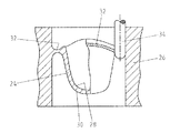
図1に、例えば国際特許公開WO−A−199947065の開示技術により作製することができる、ブランク10から作り出されたキャップ12が示されている。換言すれば、CAM(計算機援用製造)法による製造技術でブランク10から、内面14又は内側輪郭及び外面16又は外側輪郭を有するキャップ12をフライス削りで作り出すことができる。
FIG. 1 shows a
そのためにまず陽性モデルを走査してデジタル化する。ブランク10からキャップ12を作出するために、こうして得たデータを次に工作機械、例えばフライス工具に送る。
For this purpose, the positive model is first scanned and digitized. In order to create the
図1で明らかにした先行技術によれば、キャップ12とブランク10は外側側面(例えば頬側又は舌側)から出る支えピン20によって結合されたままになっており(例えば国際特許公開WO−A−200245614の図7、9、10を参照)、内面14と外面16の加工の後にブラスチングによってこれを除去する。支えピン20の太さに基づき、支えピン20の最終的切断の前にキャップ12が傾倒し、即ちブランク10の方向に旋回し、薄肉の部分に損傷の危険が起こるという欠点が生じる恐れがある。支えピンの切断の後に、以前の支えピンの区域のキャップ12の肉厚をその他の肉厚に適応させるために、通常大きな手操作再加工が必要である。
According to the prior art revealed in FIG. 1, the
その場合、軟質の又はもろい材料では、側壁が破れ、又は最小肉厚を下回る危険がある。 In that case, with soft or brittle materials there is a risk that the side walls will be torn or below the minimum wall thickness.
本発明によれば成形品−図2の実施例ではキャップ24−が適当なCAD/CAMシステムによりブランク26から作成され、その際、キャップ24は内側輪郭28及び外側輪郭30の完全な加工の後に、円周状即ち環状の縁端又はウエブ32により引続きブランク26と結合されている。その場合、円周状のウエブ32はキャップ24自体の外縁区域に延びている。内側及び外側輪郭28、30の加工の終了の後に、工具34で環状にフライス削りすることによって円周状のウエブ32を切断する。その際、工具34は下向きに送り込まれる。
In accordance with the present invention, a molded article—cap 24 in the embodiment of FIG. 2—is made from blank 26 by a suitable CAD / CAM system, with
キャップ24がごく狭いウエブで残りのブランク26と結合されているため、キャップ24がいわば位置を変えずに垂直に降下し、クッション入りの受座で受け止められるようにして、円周状のウエブ32をフライスで削り取ることができる。切断区域即ち外縁の再加工は最小限しか必要でなく、破壊の危険又は不当に薄い肉厚が生じる可能性はない。
Since the
ブランク26からキャップ24を作出するために、次のフライス加工手法を定めることが好ましい。まず工具をジグザグ状に移動して外面及び内面の荒加工、即ち粗フライス削りを行う。続いて環状のフライス加工手法により外側及び内側区域を仕上加工し、即ち仕上フライス削りにより加工する。
In order to create the
当該の段階で、ブランク26の補助的変向を可能にして3軸フライス加工を適用することができる。円周状のウエブ32の切断の前に、キャップ24の内側又は内面28の仕上加工を行う。その場合まず空洞部を加工し、次に円周状のウエブ又は縁端32を環状フライス削りによって切断する。
At this stage, triaxial milling can be applied, allowing an auxiliary turning of the blank 26. Before the
前述のようにウエブ残片の除去のために僅かな手加工しか必要でなく、このため危険が最小化される。その他の利点は簡単なCAD型取り、短時間のフライス経路計算、簡単な自動化である。また完成成形品は支えピンの残片があるものより十分に仕上げられており、従ってより高級である。 As mentioned above, little manual processing is required to remove the web debris, which minimizes the danger. Other advantages are simple CAD mold taking, short milling path calculations, and simple automation. Also, the finished molded product is more fully finished than those with the rest of the support pins and is therefore more expensive.
図3及び4の実施例でも、単なる一例としてキャップ124が適当なCAD−CAM法によりブランク126から作製される。その場合、外側輪郭128及び内側輪郭130を完全に加工した後に、キャップ124の特に外縁区域、とりわけキャップ124の大部分の外周区域は円周状即ち環状の膜132によってブランク126と結合されている。なお膜132は穴あけされている。本例では円弧に沿って延びる合計3個のスロット状の貫通穴133、134、136が設けられている。
3 and 4, the
ブランク126からキャップ124を作出するために、ブランク126に3軸フライス加工を施し、その際、ブランク126のために補助変向軸を設けることが好ましい。そのためにブランク126は、図示しないフレームに緊定される。
In order to create the
フライス加工手法は、次のように行われる。即ち外側及び内側の粗フライス削り(荒加工)が行われ、その際、ジグザグ状に曲折したフライス加工手法が追求される。続いて外面及び内面の仕上フライス削り(仕上加工)が行われ、その際、環状フライス加工手法が選ばれる。キャップ124の内側輪郭130即ち空洞部138を完全に加工した後、ブランク126と形成されたキャップ124の間に残る保持膜132に、円弧に沿った貫通穴133、134、136を形成することによって穴あけする。これもフライス削りによって行うことができる。貫通穴133、134、136の間に残るウエブ140、142、144の長さは、貫通穴133、134、136の長さの1/5ないし1/20であることが好ましい。穴あき保持膜132の形成のために、貫通穴の別の寸法又は別の個数も可能である。
The milling method is performed as follows. That is, outer and inner rough milling (rough machining) is performed, and a milling technique bent in a zigzag manner is pursued. Subsequently, finish milling (finishing) of the outer surface and the inner surface is performed, and an annular milling method is selected at that time. After the
このことに関係なく、保持膜132、即ちウエブ140、142、144はとりわけ50μmないし500μmの厚さを有するものとする。次にキャップ124を切り離すために、ブランク126を工具即ちフライス盤から取り外す。これは手操作で、又は刃物状の工具例えばメスで行うことができる。最後に、キャップ124の外側に残る保持膜132の残片を、例えば手工具でキサゲ仕上げ又はフライス削りして除去する。
Regardless of this, it is assumed that the holding
本発明に基づき、膜の残片の除去のために僅かな手操作再加工しか必要でないから、危険が最小化される。その他の利点はより簡単なCAD型取り、より短時間のフライス経路計算及び簡単な自動化に見られる。また成形品はウエブ式の成形品より十分に完成されており、従ってより高級である。 In accordance with the present invention, the risk is minimized because only a few manual reworking is required to remove the membrane debris. Other advantages can be found in simpler CAD mold taking, shorter milling path calculations and simple automation. Also, the molded product is more complete than the web-type molded product and is therefore higher quality.
実施例としてキャップに基づいて本発明を説明したが、本発明は以下の成形品の作製にも適している。即ちブリッジフレーム、歯冠、一次歯冠及びアンレー、部分歯冠及びインプラント構造などである。 Although the present invention has been described based on a cap as an example, the present invention is also suitable for manufacturing the following molded articles. Bridge frames, crowns, primary crowns and onlays, partial crowns and implant structures.
しかし本発明は歯科用品の作製だけのためのものではない。むしろその他の技術的に使用可能な部材も本発明に従って作製することができる。一例として、例えば真空技術で径違いスリーブとして、医療で細管として、機械製造で受座として、又は電気技術/電子技術で絶縁体として使用される酸化ジルコニウム製の管状部材が挙げられる。 However, the present invention is not only for the production of dental supplies. Rather, other technically usable members can also be made in accordance with the present invention. An example is a tubular member made of zirconium oxide which is used for example as a sleeve of reduced diameter in vacuum technology, as a capillary tube in medicine, as a seat in mechanical manufacture or as an insulator in electrical / electronic technology.
その場合、同様な又は類似のフライス加工手法が採用され、ウエブ又は保持膜が同様に形成される。 In that case, a similar or similar milling technique is employed, and the web or holding film is similarly formed.
Claims (19)
該成形品の外側及び内側輪郭(28、30、128、130)が完成したとき、
該成形品の大部分の外周区域において形成されている円周状のウエブの形の継手(32)又は貫通穴(133,134,136)を有する膜状継手(132)により成形品とブランクが引続き結合されており、続いて該継手(32、132)を切断することによって、ブランク(26、126)から成形品を作出することを特徴とする方法。The dental product (24, 124) is produced by cutting the blank (26, 126) from the blank (26, 126) and finishing the process by cutting the joint (32, 132) between the molded product and the remaining blank. In the production method,
When the molded article of the outer and inner contour (28,30,128,130) is completed,
The molded product and the blank are brought together by a circumferential web-shaped joint (32) or a membrane joint (132) with through holes (133, 134, 136) formed in the outer peripheral area of the majority of the molded product. A method characterized in that a molded part is produced from a blank (26, 126) by subsequently joining and subsequently cutting the joint (32, 132).
Applications Claiming Priority (5)
| Application Number | Priority Date | Filing Date | Title |
|---|---|---|---|
| EP03027104.3 | 2003-11-26 | ||
| EP03027104A EP1535587B1 (en) | 2003-11-26 | 2003-11-26 | Method for manufacturing a dental workpiece |
| DE102004027558.0 | 2004-06-04 | ||
| DE102004027558 | 2004-06-04 | ||
| PCT/EP2004/013359 WO2005051220A1 (en) | 2003-11-26 | 2004-11-25 | Method for producing a molded piece |
Publications (3)
| Publication Number | Publication Date |
|---|---|
| JP2007512062A JP2007512062A (en) | 2007-05-17 |
| JP2007512062A5 JP2007512062A5 (en) | 2008-01-10 |
| JP4869073B2 true JP4869073B2 (en) | 2012-02-01 |
Family
ID=34635226
Family Applications (1)
| Application Number | Title | Priority Date | Filing Date |
|---|---|---|---|
| JP2006540376A Expired - Fee Related JP4869073B2 (en) | 2003-11-26 | 2004-11-25 | Molded product manufacturing method |
Country Status (7)
| Country | Link |
|---|---|
| US (1) | US20070108645A1 (en) |
| EP (1) | EP1686915B1 (en) |
| JP (1) | JP4869073B2 (en) |
| AT (1) | ATE474521T1 (en) |
| AU (1) | AU2004292756B2 (en) |
| DE (1) | DE502004011429D1 (en) |
| WO (1) | WO2005051220A1 (en) |
Families Citing this family (15)
| Publication number | Priority date | Publication date | Assignee | Title |
|---|---|---|---|---|
| SE530087C2 (en) * | 2004-09-01 | 2008-02-26 | Nobel Biocare Ab | Method and apparatus for providing dental product |
| DE102006021640B3 (en) * | 2006-05-08 | 2007-10-11 | Sirona Dental Systems Gmbh | Dental prosthesis part producing method for use in tooth technician laboratory, involves specifying aesthetically relevant partial construction surface as part of outer surface of dental prosthesis part |
| ATE507796T1 (en) | 2007-06-07 | 2011-05-15 | Nobel Biocare Services Ag | METHOD FOR PRODUCING A DENTAL PRODUCT |
| EP2014254B1 (en) * | 2007-06-07 | 2018-10-31 | Nobel Biocare Services AG | Method and sintered product for forming a dental bridge |
| EP2072020A1 (en) * | 2007-12-17 | 2009-06-24 | Nobel Biocare Services AG | A method of producing a dental ceramic product |
| DE102008002952B4 (en) | 2008-07-18 | 2011-01-27 | Degudent Gmbh | Method for dimension-true sintering of a molded part and blank with blank |
| DE102009026159A1 (en) | 2009-07-13 | 2011-01-27 | Degudent Gmbh | Process for producing a molded part having an inner and outer contour |
| DE102009044461B4 (en) | 2009-11-06 | 2011-12-15 | Degudent Gmbh | Method for dimension-true sintering of a molded part |
| DE102009044460B3 (en) * | 2009-11-06 | 2011-07-14 | DeguDent GmbH, 63457 | Method for detaching molded blank from e.g. green body, for dental-technical reconstruction, involves aligning material radiations on molding blank such that materials of respective radiations and rods are discharged from radiating unit |
| WO2011084357A1 (en) | 2009-12-17 | 2011-07-14 | Schering Corporation | Modulation of pilr to treat immune disorders |
| DE102011055957B3 (en) * | 2011-12-02 | 2013-03-28 | Lennart-Marten Risch | Method and device for producing dental primary and secondary parts |
| EP2692311B1 (en) * | 2012-08-03 | 2016-06-22 | 3M Innovative Properties Company | Dental blank comprising a pre-sintered porous zirconia material , process of its production and dental article formed from said dental blank |
| US20140315154A1 (en) * | 2013-03-07 | 2014-10-23 | B&D Dental Corporation | Method for dimensional adjustment for dental scan, digitized model or restoration |
| DE102016106370A1 (en) * | 2016-03-23 | 2017-09-28 | Degudent Gmbh | Process for the preparation of a colored blank and blank |
| AT518451B1 (en) * | 2016-04-06 | 2018-05-15 | Heinrich Steger | Method for producing a dental workpiece |
Citations (9)
| Publication number | Priority date | Publication date | Assignee | Title |
|---|---|---|---|---|
| JPH05329173A (en) * | 1992-05-29 | 1993-12-14 | Nikon Corp | Preparation of dental prosthesis |
| JPH06210530A (en) * | 1991-12-26 | 1994-08-02 | I N R Kenkyusho:Kk | Composite machining device for machining medical material |
| JPH07204756A (en) * | 1994-01-10 | 1995-08-08 | Miura Kogyo Kk | Sheet forming die and its manufacture |
| JPH11151606A (en) * | 1997-11-20 | 1999-06-08 | Toshiba Mach Co Ltd | Profile machining method and machining machinery |
| JPH11333667A (en) * | 1998-05-28 | 1999-12-07 | Advance Co Ltd | Profile machining method |
| JP2002014711A (en) * | 2000-06-28 | 2002-01-18 | Nissan Motor Co Ltd | Method for searching for unmachined corner part machining area for contour machining and method for generating unmachined corner part machining area using the method |
| JP2002506674A (en) * | 1998-03-17 | 2002-03-05 | アイトゲネシッシェ テクニッシェ ホーホシューレ チューリッヒ ニヒトメタリッシェ ヴェルクシュトッフェ | Artificial crown and / or bridge denture |
| WO2002045614A1 (en) * | 2000-12-07 | 2002-06-13 | Eidgenössische Technische Hochschule Zürich Nichtmetallische Werkstoffe | Holding device for a ceramic blank |
| WO2003041606A2 (en) * | 2001-11-15 | 2003-05-22 | 3M Espe Ag | Method for producing dentures |
Family Cites Families (6)
| Publication number | Priority date | Publication date | Assignee | Title |
|---|---|---|---|---|
| SE464908B (en) | 1989-03-23 | 1991-07-01 | Nobelpharma Ab | METHOD FOR MANUFACTURING ARTIFICIAL DENTAL CHRONICLES OF ONLINE TYPE OR INPUT |
| DE19930564A1 (en) | 1999-04-16 | 2000-10-19 | Kaltenbach & Voigt | Ceramic molding, especially medical or dental prosthesis or implant, is produced by machining pressed green ceramic body to desired inner and-or outer contour prior to sintering |
| EP1087720B1 (en) * | 1999-04-16 | 2004-04-07 | Kaltenbach & Voigt GmbH & Co. KG | Method for producing ceramic medical, dental medical, technical dental and technical parts |
| US6641398B2 (en) * | 2000-08-21 | 2003-11-04 | Ivoclar Vivadent Ag | Dental materials containing a tear-off material |
| US6482284B1 (en) * | 2000-08-31 | 2002-11-19 | 3M Innovative Properties Company | Method of making a dental mill blank and support stub assembly |
| KR100414885B1 (en) | 2000-12-09 | 2004-01-24 | 주식회사 워랜텍 | Dental implant and head of a compaction drill |
-
2004
- 2004-05-25 US US10/580,854 patent/US20070108645A1/en not_active Abandoned
- 2004-11-25 WO PCT/EP2004/013359 patent/WO2005051220A1/en active Application Filing
- 2004-11-25 AU AU2004292756A patent/AU2004292756B2/en not_active Ceased
- 2004-11-25 DE DE502004011429T patent/DE502004011429D1/en active Active
- 2004-11-25 JP JP2006540376A patent/JP4869073B2/en not_active Expired - Fee Related
- 2004-11-25 AT AT04798074T patent/ATE474521T1/en active
- 2004-11-25 EP EP04798074A patent/EP1686915B1/en not_active Not-in-force
Patent Citations (9)
| Publication number | Priority date | Publication date | Assignee | Title |
|---|---|---|---|---|
| JPH06210530A (en) * | 1991-12-26 | 1994-08-02 | I N R Kenkyusho:Kk | Composite machining device for machining medical material |
| JPH05329173A (en) * | 1992-05-29 | 1993-12-14 | Nikon Corp | Preparation of dental prosthesis |
| JPH07204756A (en) * | 1994-01-10 | 1995-08-08 | Miura Kogyo Kk | Sheet forming die and its manufacture |
| JPH11151606A (en) * | 1997-11-20 | 1999-06-08 | Toshiba Mach Co Ltd | Profile machining method and machining machinery |
| JP2002506674A (en) * | 1998-03-17 | 2002-03-05 | アイトゲネシッシェ テクニッシェ ホーホシューレ チューリッヒ ニヒトメタリッシェ ヴェルクシュトッフェ | Artificial crown and / or bridge denture |
| JPH11333667A (en) * | 1998-05-28 | 1999-12-07 | Advance Co Ltd | Profile machining method |
| JP2002014711A (en) * | 2000-06-28 | 2002-01-18 | Nissan Motor Co Ltd | Method for searching for unmachined corner part machining area for contour machining and method for generating unmachined corner part machining area using the method |
| WO2002045614A1 (en) * | 2000-12-07 | 2002-06-13 | Eidgenössische Technische Hochschule Zürich Nichtmetallische Werkstoffe | Holding device for a ceramic blank |
| WO2003041606A2 (en) * | 2001-11-15 | 2003-05-22 | 3M Espe Ag | Method for producing dentures |
Also Published As
| Publication number | Publication date |
|---|---|
| EP1686915B1 (en) | 2010-07-21 |
| EP1686915A1 (en) | 2006-08-09 |
| AU2004292756B2 (en) | 2010-12-09 |
| DE502004011429D1 (en) | 2010-09-02 |
| JP2007512062A (en) | 2007-05-17 |
| ATE474521T1 (en) | 2010-08-15 |
| US20070108645A1 (en) | 2007-05-17 |
| WO2005051220A1 (en) | 2005-06-09 |
| AU2004292756A1 (en) | 2005-06-09 |
Similar Documents
| Publication | Publication Date | Title |
|---|---|---|
| JP4869073B2 (en) | Molded product manufacturing method | |
| EP1420714B1 (en) | Method for producing casting molds | |
| EP1610708B1 (en) | Method and system for fabricating a dental coping | |
| US20170196665A1 (en) | System and method for manufacturing of dental crowns and crown components | |
| US6495073B2 (en) | Method for the manufacture of medical, dental-medical, dental-technical and technical parts from ceramics | |
| US6974323B2 (en) | Method for automated production of ceramic dental restorations and prostheses | |
| US7967606B2 (en) | Process for manufacturing custom crown copings and infrastructures | |
| EP1486181B1 (en) | Method of making a dental restoration and apparatus therefor | |
| US20010034010A1 (en) | Method and apparatus for preparing dental restorations | |
| CN111281581B (en) | Method for designing and manufacturing a dental component | |
| JP2002320626A (en) | Cutting and grinding machine for manufacturing dental care workpieces to be processed | |
| JP2003515429A (en) | Method of making ceramic dentures and very durable ceramic dentures produced according to this method | |
| US20070154864A1 (en) | Method of manufacturing a dental part | |
| JP4768985B2 (en) | Method for making dental ceramic structure | |
| WO2002076327A1 (en) | A method of and an arrangement for a dental restoration | |
| JPH10192305A (en) | Production of artificial adaptation material and its device | |
| JPH0435180B2 (en) | ||
| CA2519538A1 (en) | Method for the production of a dental moulded part | |
| EP1535587B1 (en) | Method for manufacturing a dental workpiece | |
| JPH08299366A (en) | Manufacture of dental prosthesis with operating projecting part |
Legal Events
| Date | Code | Title | Description |
|---|---|---|---|
| A521 | Request for written amendment filed |
Free format text: JAPANESE INTERMEDIATE CODE: A523 Effective date: 20071116 |
|
| A621 | Written request for application examination |
Free format text: JAPANESE INTERMEDIATE CODE: A621 Effective date: 20071116 |
|
| A131 | Notification of reasons for refusal |
Free format text: JAPANESE INTERMEDIATE CODE: A131 Effective date: 20091117 |
|
| A601 | Written request for extension of time |
Free format text: JAPANESE INTERMEDIATE CODE: A601 Effective date: 20100126 |
|
| A602 | Written permission of extension of time |
Free format text: JAPANESE INTERMEDIATE CODE: A602 Effective date: 20100202 |
|
| A601 | Written request for extension of time |
Free format text: JAPANESE INTERMEDIATE CODE: A601 Effective date: 20100413 |
|
| A602 | Written permission of extension of time |
Free format text: JAPANESE INTERMEDIATE CODE: A602 Effective date: 20100420 |
|
| A521 | Request for written amendment filed |
Free format text: JAPANESE INTERMEDIATE CODE: A523 Effective date: 20100514 |
|
| A131 | Notification of reasons for refusal |
Free format text: JAPANESE INTERMEDIATE CODE: A131 Effective date: 20101116 |
|
| A601 | Written request for extension of time |
Free format text: JAPANESE INTERMEDIATE CODE: A601 Effective date: 20110204 |
|
| A602 | Written permission of extension of time |
Free format text: JAPANESE INTERMEDIATE CODE: A602 Effective date: 20110214 |
|
| A601 | Written request for extension of time |
Free format text: JAPANESE INTERMEDIATE CODE: A601 Effective date: 20110304 |
|
| A602 | Written permission of extension of time |
Free format text: JAPANESE INTERMEDIATE CODE: A602 Effective date: 20110311 |
|
| A601 | Written request for extension of time |
Free format text: JAPANESE INTERMEDIATE CODE: A601 Effective date: 20110405 |
|
| A602 | Written permission of extension of time |
Free format text: JAPANESE INTERMEDIATE CODE: A602 Effective date: 20110412 |
|
| A521 | Request for written amendment filed |
Free format text: JAPANESE INTERMEDIATE CODE: A523 Effective date: 20110513 |
|
| TRDD | Decision of grant or rejection written | ||
| A01 | Written decision to grant a patent or to grant a registration (utility model) |
Free format text: JAPANESE INTERMEDIATE CODE: A01 Effective date: 20111025 |
|
| A01 | Written decision to grant a patent or to grant a registration (utility model) |
Free format text: JAPANESE INTERMEDIATE CODE: A01 |
|
| A61 | First payment of annual fees (during grant procedure) |
Free format text: JAPANESE INTERMEDIATE CODE: A61 Effective date: 20111115 |
|
| R150 | Certificate of patent or registration of utility model |
Free format text: JAPANESE INTERMEDIATE CODE: R150 |
|
| FPAY | Renewal fee payment (event date is renewal date of database) |
Free format text: PAYMENT UNTIL: 20141125 Year of fee payment: 3 |
|
| LAPS | Cancellation because of no payment of annual fees |