JP4868552B2 - Binding machine drive - Google Patents
Binding machine drive Download PDFInfo
- Publication number
- JP4868552B2 JP4868552B2 JP2009525597A JP2009525597A JP4868552B2 JP 4868552 B2 JP4868552 B2 JP 4868552B2 JP 2009525597 A JP2009525597 A JP 2009525597A JP 2009525597 A JP2009525597 A JP 2009525597A JP 4868552 B2 JP4868552 B2 JP 4868552B2
- Authority
- JP
- Japan
- Prior art keywords
- binding
- link
- carriage
- saddle stitcher
- gravity
- Prior art date
- Legal status (The legal status is an assumption and is not a legal conclusion. Google has not performed a legal analysis and makes no representation as to the accuracy of the status listed.)
- Expired - Fee Related
Links
Images


Classifications
-
- B—PERFORMING OPERATIONS; TRANSPORTING
- B42—BOOKBINDING; ALBUMS; FILES; SPECIAL PRINTED MATTER
- B42B—PERMANENTLY ATTACHING TOGETHER SHEETS, QUIRES OR SIGNATURES OR PERMANENTLY ATTACHING OBJECTS THERETO
- B42B2/00—Permanently attaching together sheets, quires or signatures by stitching with filamentary material, e.g. textile threads
- B42B2/02—Machines for stitching with thread
-
- B—PERFORMING OPERATIONS; TRANSPORTING
- B42—BOOKBINDING; ALBUMS; FILES; SPECIAL PRINTED MATTER
- B42B—PERMANENTLY ATTACHING TOGETHER SHEETS, QUIRES OR SIGNATURES OR PERMANENTLY ATTACHING OBJECTS THERETO
- B42B9/00—Devices common to machines for carrying out the processes according to more than one of the preceding main groups
- B42B9/04—Devices common to machines for carrying out the processes according to more than one of the preceding main groups for conveying downwardly-open signatures
Landscapes
- Engineering & Computer Science (AREA)
- Textile Engineering (AREA)
- Mechanical Engineering (AREA)
- Transmission Devices (AREA)
- Folding Of Thin Sheet-Like Materials, Special Discharging Devices, And Others (AREA)
- Sewing Machines And Sewing (AREA)
Description
本願は、2006年8月18日に出願されかつ引用したことにより本明細書に記載されたものとする米国特許仮出願第60/838635号明細書の利益を請求する。 This application claims the benefit of US Provisional Application No. 60 / 8386,635, filed and cited herein on August 18, 2006.
背景
中とじ機等の丁合い機が知られている。中とじ機において、シート材料フィーダ又はホッパから送出された複数の折丁は、鞍型コンベヤにおいて収集される。とじ機は、収集された折丁を綴じる。
Background Collating machines such as saddle stitch machines are known. In the saddle stitcher, a plurality of signatures fed from a sheet material feeder or hopper are collected on a saddle type conveyor. The binding machine binds the collected signatures.
とじ機は例えば折丁を収集し、折丁の完全なセットを組み立て、とじ機を使用して折丁を綴じ合わせる。折丁は、中央折りに開かれ、綴じ機構を通って搬送されるためにフィーダによって鞍型チェーン上に収集される。これらの綴じられた折丁、若しくは刷本は、次いで、さらなる処理のために、例えば綴じられていない縁部を仕上げ裁ちするために、鞍型コンベヤから取り出される。 The binding machine, for example, collects signatures, assembles a complete set of signatures, and binds the signatures using the binding machine. The signature is opened in a central fold and collected on the saddle chain by the feeder for transport through the binding mechanism. These bound signatures, or booklets, are then removed from the saddle conveyor for further processing, for example, finishing the unbound edges.
米国特許第4196835号明細書は、折丁のグループが移動している時にこの折丁のグループを綴じる綴じアセンブリを有する丁合い機を開示している。綴じアセンブリは、あらゆる往復する機構を案内するためにレールの使用を必要としない。 U.S. Pat. No. 4,196,835 discloses a collating machine having a binding assembly that binds a group of signatures as they are moving. The binding assembly does not require the use of rails to guide any reciprocating mechanism.
米国特許第6866257号明細書は、綴じ領域において案内エレメントを有する丁合−綴じ装置を開示しており、この場合、綴じ領域における折り畳まれたシート又は折丁の走行が改良され、綴じ領域の入口及び出口における妨害から生じる停止時間が短縮される。 U.S. Pat. No. 6,866,257 discloses a collating and binding device having guide elements in the binding area, in which the travel of the folded sheet or signature in the binding area is improved and the entrance of the binding area is disclosed. And the downtime resulting from disturbance at the exit is reduced.
米国特許出願公開第2005/0285319号明細書は、とじ機と、綴じられていない被印刷製品を綴じるためにとじ機に通過させるためのコンベヤとを開示している。コンベヤは、綴じられない被印刷製品に係合しかつこれらの被印刷製品をとじ機に通過させるための複数の押付けエレメントを有するタイミングベルトを有する。 US Patent Application Publication No. 2005/0285319 discloses a binding machine and a conveyor for passing unbound printed products through the binding machine for binding. The conveyor has a timing belt having a plurality of pressing elements for engaging unprinted printed products and passing these printed products through the binding machine.
発明の概要
本発明の実施形態によれば、とじ機は、重心を有するキャリッジを有する。キャリッジは、延長位置と後退位置との間を移動可能である。キャリッジを支持するための少なくとも1つのベアリングが設けられている。キャリッジを駆動するために作動リンクが設けられている。重心を介して又は重心とベアリングとの間においてリンクの駆動力が提供される。
SUMMARY OF THE INVENTION According to an embodiment of the present invention, a binding machine has a carriage having a center of gravity. The carriage is movable between an extended position and a retracted position. At least one bearing is provided for supporting the carriage. An actuation link is provided for driving the carriage. A link driving force is provided through the center of gravity or between the center of gravity and the bearing.
本発明の別の実施形態によれは、とじ機は、重心を有する可動なキャリッジを有している。キャリッジは、延長位置と後退位置との間を移動可能である。キャリッジを駆動するための作動リンクが設けられている。キャリッジが延長位置又は後退位置にある時に重心を介してリンクの駆動力が提供される。 According to another embodiment of the invention, the binding machine has a movable carriage having a center of gravity. The carriage is movable between an extended position and a retracted position. An operating link for driving the carriage is provided. Link driving force is provided through the center of gravity when the carriage is in the extended or retracted position.
本発明の別の実施形態によれは、中とじ機は複数のホッパを有している。複数のホッパからシート材料を収集するコンベヤが設けられている。とじ機が設けられている。とじ機は、中心を有するキャリッジを有する。キャリッジは、延長位置と後退位置との間を移動可能である。キャリッジを支持するために少なくとも1つのベアリングが設けられている。キャリッジを駆動するために作動リンクが設けられている。重心を介して又は重心とベアリングとの間においてリンクの駆動力が提供される。 According to another embodiment of the invention, the saddle stitcher has a plurality of hoppers. A conveyor is provided for collecting sheet material from a plurality of hoppers. A binding machine is provided. The binding machine has a carriage having a center. The carriage is movable between an extended position and a retracted position. At least one bearing is provided to support the carriage. An actuation link is provided for driving the carriage. A link driving force is provided through the center of gravity or between the center of gravity and the bearing.
本発明の実施形態によれは、シート材料を綴じる方法は、重心を介して又は重心とベアリングとの間においてとじ機に駆動力を提供し、シート材料を綴じることを含む。 According to an embodiment of the present invention, a method for binding sheet material includes providing a driving force to the binding machine through the center of gravity or between the center of gravity and the bearing, and binding the sheet material.
本発明の別の実施形態によれば、シート材料を綴じる方法は、綴じキャリッジに駆動力を提供し、綴じキャリッジを後退位置と延長位置との間で移動させかつ綴じサイクルを完了するために後退位置へ戻し、綴じサイクルの間にシート材料を綴じることを含む。綴じサイクルにおける少なくとも1つの時点において綴じキャリッジの重心を介して駆動力が提供される。 According to another embodiment of the present invention, a method for binding sheet material provides a driving force for a binding carriage, moves the binding carriage between a retracted position and an extended position, and retracts to complete a binding cycle. Returning to position and binding the sheet material during the binding cycle. Driving force is provided through the center of gravity of the binding carriage at at least one point in the binding cycle.
本発明の好適な実施形態は図面を参照しながら説明される。 Preferred embodiments of the present invention will be described with reference to the drawings.
好適な実施形態の詳細な説明
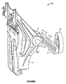
図1及び2は従来のとじ機10を示している。キャリッジ11は、シャフト12上を摺動するボールブシュ13A,13Bによって支持されている。キャリッジ11は、クランク16及び作動リンク15を介して揺動する。クランク16が回転すると、作動リンク15は方向Xに揺動する。作動リンク15はベアリングブロック14によってキャリッジ11に結合されている。作動リンク15は、力F15を箇所A1において提供し、この力はキャリッジ11に伝達される。
Detailed Description of the Preferred Embodiments FIGS. 1 and 2 show a
図2は、最も上流の位置におけるキャリッジ11を示している。この上流位置において、キャリッジ11は、ゼロ速度を有するが、クランク16及び作動リンク15の作用により、最大加速下にある。キャリッジ11に対する作動リンク15の力F15は、慣性力F1を生じる。慣性力F1はリンク力F15と等しいが、反対方向である。箇所A1において提供される作動リンク15の力F15とキャリッジの重心24との間のずれにより、モーメントが発生する。生じるモーメントは、ボールブシュ13A,13Bそれぞれにおいて力F13A,F13Bによって支持される。図1及び2に示されているように、作動リンク15の位置は、力F15が、ボールブシュ13A,13Bよりも重心24から離れて加えられるようになっている。慣性力F1は極めて大きく、これは、ボールブシュ13A,13Bに極めて大きな力F13A,F13Bを生ぜしめる。
FIG. 2 shows the
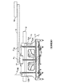
図3A,3Bは、本発明の実施形態によるとじ機100を示している。クランク116は作動リンク115を駆動し、時計回り又は逆時計回りに回転する。図3Aに示された位置において、リンク115は、クランク116に関して3時の位置に配置されている。この位置において、キャリッジ111はクランク116に最も近い。リンク115がクランク116に対して9時の位置にある場合、キャリッジ111はクランク116から最も離れている。作動リンク115は、枢軸114においてキャリッジ111に結合されており、方向Yにキャリッジ111を揺動させる。ベアリングレール113及びリニアボールベアリング112A,112Bはキャリッジ111を支持している。作動リンク115は、作動リンク115がクランク116に対して9時及び3時の位置にある場合、揺動方向に対して水平及び平行である。リンク115の枢軸114は、キャリッジ111の重心124を通って延びる中心線123上に位置している。リンク115が水平である場合、例えば9時又は3時の位置にある場合、キャリッジ111の慣性力F111は作動リンク115を通って延び、力F115は、中心線123に沿った箇所A2において加えられる。すなわち、箇所A2において加えられる力F115と重心124との間の横方向ずれが存在しない。その結果、慣性力F111がベアリング112A,112Bに伝達されない。
3A and 3B show a
作動リンク115が水平位置にない場合、例えばクランク116が3時位置と9時位置との間を回転しながら、ベアリング112A,112Bは、F115とキャリッジ111の慣性力F111との間の垂直方向ずれにより生じる慣性力F111のための支持を提供する。ベアリング112A,112Bにおける支持は、リンク115から重心124までの垂直方向距離に等しく、生ぜしめられたモーメントを平衡させる。
If the
図3Bはとじ機100の上面図を示している。作動リンク115の力F115の箇所A2とキャリッジ111の慣性力F111とは、重心124を通る同じ垂直平面に位置している。同じ垂直平面における慣性力F111と力F115との位置決めは、リニアベアリング112A,112Bにおける支持荷重を減じる。すなわち、作動リンクの力F115の提供箇所A2を重心24に近付けることによって、ベアリング112A,112Bにおける力が減じられる。
FIG. 3B shows a top view of the
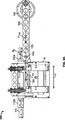
図4及び図5は本発明による別の好適な実施形態を示している。とじ機200は、リニアボールベアリング212A,212Bに取り付けられたキャリッジ211を有している。クランク216はリンク217に結合されている。ロッカーアーム218は、クレビス225に可動に取り付けられているので、ロッカーアーム218は方向Dに揺動することができる。ロッカーアーム218は作動リンク215に結合されており、作動リンク215は枢軸222においてキャリッジ211に結合されている。クランク216が回転させられると、リンク217が移動し、ロッカーアーム218を移動させる。ロッカーアーム218はリンク217の動作を作動リンク215に伝達する。作動リンク215は引き続き枢軸222を介してキャリッジ211を移動させ、キャリッジ211を揺動させる。
4 and 5 show another preferred embodiment according to the present invention. The binding
さらに図5に示されているように、作動リンク215の力F215は、キャリッジ211の慣性力F211と同じ垂直平面に位置する箇所A3において提供される。同じ垂直平面における慣性力F211及び力F215の位置決めは、リニアベアリング212A,212Bにおける支持荷重を減じる。
As further shown in FIG. 5, the force F 215 of the
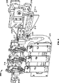
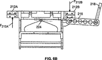
図6Aは、延長位置218aにおけるロッカーアーム218と、後退位置218bのための経路とを示している。ロッカーアーム218が延長位置218a又は後退位置218bにある場合、力F215が箇所Aにおいて提供され、重心224を通って移動する。箇所A3から重心224までの垂直距離はゼロである。すなわち、慣性力F211はリニアベアリング212A,212Bに伝達されない。ロッカーアーム218が、図6Bに示されているように延長位置218aと後退位置218bとの間のあらゆる位置にある場合、力F215は、重心224の近傍に提供される。F215から重心224までの垂直距離は減じられ、リニアボールベアリング212A,212Bにおける減じられた荷重F212A,F212Bとを生じる。すなわち、重心224とリニアボールベアリング212A,212Bとの間に作動力F215を提供することにより、リニアボールベアリング212A,212Bにおける支持荷重が減じられる。
FIG. 6A shows the
前記明細書において、発明は、発明の典型的な実施形態及び実施例に関して説明された。しかしながら、請求の範囲に示された発明のより広い精神及び範囲から逸脱することなくそれらの実施形態に様々な変更を加えることができることは明らかである。したがって、明細書及び図面は、制限的な意味ではなく例示的な形式でみなされるべきである。 In the foregoing specification, the invention has been described with reference to exemplary embodiments and examples of the invention. It will be apparent, however, that various modifications can be made to these embodiments without departing from the broader spirit and scope of the claimed invention. The specification and drawings are accordingly to be regarded in an illustrative manner rather than a restrictive sense.
10 とじ機、 11 キャリッジ、 12 シャフト、 13A,13B ボールブシュ、 14 ベアリングブロック、 15 作動リンク、 16 クランク、 24 重心、 100 とじ機、 111 キャリッジ、 112A,112B リニア玉ベアリング、 113 支持レール、 114 枢軸、 115 作動リンク、 116 クランク、 123 中心線、 124 重心、 200 とじ機、 211 キャリッジ、 212A,212B リニア玉ベアリング、 215 作動リンク、 217 リンク、 218 ロッカーアーム、 222 枢軸 10 stitcher, 11 carriage, 12 shaft, 13A, 13B ball bushing, 14 bearing block, 15 actuating link, 16 crank, 24 center of gravity, 100 stitcher, 111 carriage, 112A, 112B linear ball bearing, 113 support rail, 114 pivot , 115 actuating link, 116 crank, 123 center line, 124 center of gravity, 200 stitcher, 211 carriage, 212A, 212B linear ball bearing, 215 actuating link, 217 link, 218 rocker arm, 222 pivot
Claims (16)
複数のホッパが設けられており、
該複数のホッパからシート材料を収集するコンベヤが設けられており、
とじ機が設けられており、該とじ機が、
重心を有するキャリッジを有しており、該キャリッジが、延長位置と後退位置との間を可動であり、
前記とじ機が、前記キャリッジを支持するための少なくとも1つのベアリングを有しており、
前記とじ機が、前記キャリッジを駆動するための作動リンクを有しており、該作動リンクの駆動力が、前記重心を介して又は該重心とベアリングとの間において提供されるようになっていることを特徴とする、中とじ機。In the saddle stitcher,
There are multiple hoppers
A conveyor is provided for collecting sheet material from the plurality of hoppers;
A binding machine is provided, and the binding machine is
A carriage having a center of gravity, the carriage being movable between an extended position and a retracted position;
The binding machine has at least one bearing for supporting the carriage;
The binding machine has an operating link for driving the carriage, and the driving force of the operating link is provided via the center of gravity or between the center of gravity and the bearing. A saddle stitcher characterized by that.
綴じキャリッジに駆動力を提供するステップと、
前記綴じキャリッジを、後退位置と延長位置との間で移動させかつ綴じサイクルを完了するために後退位置へ戻すステップと、
綴じサイクルの間にシート材料を綴じるステップと、
前記駆動力が、綴じサイクルにおける少なくとも1つの時点の間に綴じキャリッジの重心を介して提供され、
前記綴じキャリッジに駆動力を提供するステップが、リンクを使用することを含み、前記綴じキャリッジに駆動力を提供するステップが、リンクに結合されたクランクを使用することを含み、前記綴じキャリッジに駆動力を提供するステップが、第2のリンクを使用することを含み、前記綴じキャリッジに駆動力を提供するステップが、第2のリンクに結合されたクランクを使用することを含み、前記第2のリンクが、ロッカーアームによってリンクに結合されていることを特徴とする、シート材料を綴じる方法。In the method of binding the sheet material,
Providing a driving force to the binding carriage;
Moving the binding carriage between a retracted position and an extended position and returning to the retracted position to complete the binding cycle;
Binding the sheet material during the binding cycle;
The driving force is provided via the center of gravity of the binding carriage during at least one point in the binding cycle;
Providing a driving force to the binding carriage includes using a link, and providing a driving force to the binding carriage includes using a crank coupled to the link, and driving the binding carriage Providing a force includes using a second link, and providing a driving force to the binding carriage includes using a crank coupled to the second link; A method for binding sheet material, characterized in that the link is connected to the link by a rocker arm .
Applications Claiming Priority (3)
| Application Number | Priority Date | Filing Date | Title |
|---|---|---|---|
| US83863506P | 2006-08-18 | 2006-08-18 | |
| US60/838,635 | 2006-08-18 | ||
| PCT/US2007/018425 WO2008021566A2 (en) | 2006-08-18 | 2007-08-20 | Stitcher drive |
Publications (2)
| Publication Number | Publication Date |
|---|---|
| JP2010501371A JP2010501371A (en) | 2010-01-21 |
| JP4868552B2 true JP4868552B2 (en) | 2012-02-01 |
Family
ID=39082816
Family Applications (1)
| Application Number | Title | Priority Date | Filing Date |
|---|---|---|---|
| JP2009525597A Expired - Fee Related JP4868552B2 (en) | 2006-08-18 | 2007-08-20 | Binding machine drive |
Country Status (5)
| Country | Link |
|---|---|
| US (1) | US7857298B2 (en) |
| EP (1) | EP2051863A4 (en) |
| JP (1) | JP4868552B2 (en) |
| CN (1) | CN101489800B (en) |
| WO (1) | WO2008021566A2 (en) |
Families Citing this family (2)
| Publication number | Priority date | Publication date | Assignee | Title |
|---|---|---|---|---|
| JP4868552B2 (en) * | 2006-08-18 | 2012-02-01 | ゴス インターナショナル アメリカス インコーポレイテッド | Binding machine drive |
| US9238567B2 (en) | 2012-12-31 | 2016-01-19 | Goss International Americas, Inc. | Stitching sections of a tabloid newspaper |
Family Cites Families (16)
| Publication number | Priority date | Publication date | Assignee | Title |
|---|---|---|---|---|
| US3601388A (en) * | 1969-02-03 | 1971-08-24 | Jack M Hilliard | Infeed method and mechanism for book-sewing machine |
| US4196835A (en) * | 1979-02-21 | 1980-04-08 | Harris Corporation | Stitching machine |
| JPH0329169Y2 (en) * | 1980-12-25 | 1991-06-21 | ||
| CH662987A5 (en) * | 1984-01-26 | 1987-11-13 | Grapha Holding Ag | SADDLE STAPER. |
| US4986864A (en) * | 1989-04-05 | 1991-01-22 | Webway Incorporated | Page binding method and machine |
| CH691229A5 (en) * | 1995-09-08 | 2001-05-31 | Grapha Holding Ag | Saddle stitcher. |
| EP0958942B1 (en) * | 1998-05-18 | 2003-02-12 | Grapha-Holding Ag | Stapler apparatus for a gathering and stitching machine with a collecter chain |
| DE10058796A1 (en) * | 2000-05-09 | 2001-11-15 | Heidelberger Druckmasch Ag | Saddle stitcher with separate drives |
| EP1182044B1 (en) * | 2000-08-24 | 2005-06-29 | Hewlett-Packard Company, A Delaware Corporation | Beam for supporting a carriage |
| DE10130662A1 (en) * | 2001-06-28 | 2003-01-16 | Heidelberger Druckmasch Ag | Saddle stitcher with a guide element in the stitching area |
| DE102004011973B4 (en) * | 2004-03-10 | 2017-03-23 | Hohner Maschinenbau Gmbh | Saddle stitcher with a stitching station |
| CN100577540C (en) * | 2004-06-29 | 2010-01-06 | 高斯国际美洲公司 | Binding device and printed matter binding method |
| DE502004009572D1 (en) * | 2004-08-24 | 2009-07-16 | Mueller Martini Holding Ag | Method for stapling printed products and stapling machine |
| DE102005046683A1 (en) * | 2005-09-29 | 2007-04-05 | Heidelberger Druckmaschinen Ag | stapler |
| US7588240B2 (en) * | 2006-08-09 | 2009-09-15 | Goss International Americas, Inc. | Saddle stitcher with individual stitcher drives |
| JP4868552B2 (en) * | 2006-08-18 | 2012-02-01 | ゴス インターナショナル アメリカス インコーポレイテッド | Binding machine drive |
-
2007
- 2007-08-20 JP JP2009525597A patent/JP4868552B2/en not_active Expired - Fee Related
- 2007-08-20 WO PCT/US2007/018425 patent/WO2008021566A2/en not_active Ceased
- 2007-08-20 EP EP07837105.1A patent/EP2051863A4/en not_active Withdrawn
- 2007-08-20 US US11/894,469 patent/US7857298B2/en not_active Expired - Fee Related
- 2007-08-20 CN CN2007800269980A patent/CN101489800B/en not_active Expired - Fee Related
Also Published As
| Publication number | Publication date |
|---|---|
| JP2010501371A (en) | 2010-01-21 |
| CN101489800A (en) | 2009-07-22 |
| US20080042337A1 (en) | 2008-02-21 |
| EP2051863A2 (en) | 2009-04-29 |
| CN101489800B (en) | 2011-06-08 |
| WO2008021566A3 (en) | 2008-06-26 |
| US7857298B2 (en) | 2010-12-28 |
| EP2051863A4 (en) | 2013-09-25 |
| WO2008021566A2 (en) | 2008-02-21 |
Similar Documents
| Publication | Publication Date | Title |
|---|---|---|
| JP5786009B2 (en) | Digitally printed newspaper production equipment | |
| JP4450053B2 (en) | Recording material post-processing apparatus and image forming system | |
| CN107108137B (en) | Plate supply device | |
| US8118295B2 (en) | Stitcher/stapler for binding multi-sheet collations and method of operating the same | |
| CN101734037B (en) | Gathering and stitching unit | |
| CN101233061B (en) | paper handling device | |
| JP2000062345A (en) | Wire stitching machine for collecting binding apparatus with collecting chain | |
| JP4868552B2 (en) | Binding machine drive | |
| EP1732832B1 (en) | Signature transport device | |
| EP1547951B1 (en) | Signature-stacking apparatus | |
| CN1939754A (en) | Stitching apparatus | |
| JP2009120351A (en) | Paper bundle transfer device | |
| US20110095468A1 (en) | Reconfigurable stitcher for binding consecutive variable thickness collations | |
| US8306654B2 (en) | Transport and alignment system for producing variable thickness collations | |
| US1608838A (en) | Book-stitching machine | |
| JP2010500260A (en) | Saddle stitcher with individual saddle stitcher drive | |
| JP2012180193A (en) | Sheet post-processing device and image forming apparatus including the same | |
| CN100522645C (en) | Device for manufacturing thread-stitched book blocks which comprise folded printed sheets | |
| US7988138B2 (en) | Gatherer stitcher with variable chain pitch | |
| JP5129036B2 (en) | Sheet folding apparatus, sheet conveying apparatus, sheet post-processing apparatus, and image forming apparatus | |
| JPH0577520B2 (en) | ||
| JP6656659B2 (en) | Paper binding device | |
| JP4471207B2 (en) | Sheet post-processing device | |
| JP5527084B2 (en) | Paper processing apparatus and image forming apparatus | |
| JP2011116528A (en) | Paper sheet post-processing device, and image forming device |
Legal Events
| Date | Code | Title | Description |
|---|---|---|---|
| RD04 | Notification of resignation of power of attorney |
Free format text: JAPANESE INTERMEDIATE CODE: A7424 Effective date: 20101227 Free format text: JAPANESE INTERMEDIATE CODE: A7424 Effective date: 20101228 |
|
| A131 | Notification of reasons for refusal |
Free format text: JAPANESE INTERMEDIATE CODE: A131 Effective date: 20110309 |
|
| A601 | Written request for extension of time |
Free format text: JAPANESE INTERMEDIATE CODE: A601 Effective date: 20110609 |
|
| A602 | Written permission of extension of time |
Free format text: JAPANESE INTERMEDIATE CODE: A602 Effective date: 20110616 |
|
| A601 | Written request for extension of time |
Free format text: JAPANESE INTERMEDIATE CODE: A601 Effective date: 20110711 |
|
| A602 | Written permission of extension of time |
Free format text: JAPANESE INTERMEDIATE CODE: A602 Effective date: 20110719 |
|
| A601 | Written request for extension of time |
Free format text: JAPANESE INTERMEDIATE CODE: A601 Effective date: 20110809 |
|
| A602 | Written permission of extension of time |
Free format text: JAPANESE INTERMEDIATE CODE: A602 Effective date: 20110816 |
|
| A521 | Request for written amendment filed |
Free format text: JAPANESE INTERMEDIATE CODE: A523 Effective date: 20110901 |
|
| TRDD | Decision of grant or rejection written | ||
| A01 | Written decision to grant a patent or to grant a registration (utility model) |
Free format text: JAPANESE INTERMEDIATE CODE: A01 Effective date: 20111013 |
|
| A01 | Written decision to grant a patent or to grant a registration (utility model) |
Free format text: JAPANESE INTERMEDIATE CODE: A01 |
|
| A61 | First payment of annual fees (during grant procedure) |
Free format text: JAPANESE INTERMEDIATE CODE: A61 Effective date: 20111111 |
|
| R150 | Certificate of patent or registration of utility model |
Free format text: JAPANESE INTERMEDIATE CODE: R150 |
|
| FPAY | Renewal fee payment (event date is renewal date of database) |
Free format text: PAYMENT UNTIL: 20141125 Year of fee payment: 3 |
|
| LAPS | Cancellation because of no payment of annual fees |