JP4867006B2 - Media processing device - Google Patents
Media processing device Download PDFInfo
- Publication number
- JP4867006B2 JP4867006B2 JP2006209259A JP2006209259A JP4867006B2 JP 4867006 B2 JP4867006 B2 JP 4867006B2 JP 2006209259 A JP2006209259 A JP 2006209259A JP 2006209259 A JP2006209259 A JP 2006209259A JP 4867006 B2 JP4867006 B2 JP 4867006B2
- Authority
- JP
- Japan
- Prior art keywords
- card
- medium
- surface plate
- housing member
- housing
- Prior art date
- Legal status (The legal status is an assumption and is not a legal conclusion. Google has not performed a legal analysis and makes no representation as to the accuracy of the status listed.)
- Expired - Fee Related
Links
- 238000012545 processing Methods 0.000 title claims description 43
- 230000007246 mechanism Effects 0.000 claims description 28
- 230000004308 accommodation Effects 0.000 claims description 19
- 238000003825 pressing Methods 0.000 claims description 11
- 238000003780 insertion Methods 0.000 description 14
- 230000037431 insertion Effects 0.000 description 14
- 230000010365 information processing Effects 0.000 description 6
- 238000012986 modification Methods 0.000 description 5
- 230000004048 modification Effects 0.000 description 5
- 239000000758 substrate Substances 0.000 description 3
- 238000010586 diagram Methods 0.000 description 2
- 238000004049 embossing Methods 0.000 description 2
- 238000000034 method Methods 0.000 description 2
- 239000004033 plastic Substances 0.000 description 2
- 230000005540 biological transmission Effects 0.000 description 1
- 238000004891 communication Methods 0.000 description 1
- 238000013461 design Methods 0.000 description 1
- 238000007599 discharging Methods 0.000 description 1
- 230000000694 effects Effects 0.000 description 1
- 238000009434 installation Methods 0.000 description 1
- 239000000463 material Substances 0.000 description 1
- 230000013011 mating Effects 0.000 description 1
- 239000002184 metal Substances 0.000 description 1
- 230000003287 optical effect Effects 0.000 description 1
Images


Landscapes
- Conveying Record Carriers (AREA)
Description
本発明は、例えば銀行カードやクレジットカードなどのカード状媒体に対して情報の読み取り又は書き込みを行う媒体処理装置に関する。 The present invention relates to a medium processing apparatus that reads or writes information on a card-like medium such as a bank card or a credit card.
従来から、金融機関などで使用され、キャッシュレスや個人認証などを実現するカードとして、プラスチック基板表面に磁気ストライプが形成された磁気カードや、プラスチック基板内部に集積回路チップ(ICチップ)が埋設されるとともに、表面にIC端子が配置されたICカードがある。そして、これら磁気カードやICカードに対する情報の記録又は再生は、磁気ヘッドやIC接点を備えたカードリーダによって行われる(例えば特許文献1参照)。 Conventionally, as a card used in financial institutions to realize cashless and personal authentication, a magnetic card having a magnetic stripe formed on the surface of a plastic substrate and an integrated circuit chip (IC chip) embedded in the plastic substrate In addition, there is an IC card having IC terminals arranged on the surface. Information is recorded or reproduced on the magnetic card or the IC card by a card reader provided with a magnetic head or an IC contact (see, for example, Patent Document 1).
特許文献1に開示されたカードリーダは、磁気カード表面上の磁気ストライプに磁気ヘッドを接触・摺動させることで、磁気カードに格納された磁気情報を読み取ったり、磁気カードに対して新たな磁気情報を書き込んだりする。また、ICカード表面上の金属端子(外部端子)にIC接点を接触・当接させることで、ICカードに格納された電子情報を読み取ったり、ICカードに対して新たな電子情報を書き込んだりする。 The card reader disclosed in Patent Document 1 reads magnetic information stored in a magnetic card by making a magnetic head contact and slide on a magnetic stripe on the surface of the magnetic card, or a new magnetic Write information. In addition, by contacting and abutting an IC contact with a metal terminal (external terminal) on the surface of the IC card, electronic information stored in the IC card is read or new electronic information is written on the IC card. .
ここで、特許文献1に開示されたカードリーダは、カード挿入口から挿入された磁気カード又はICカードを、磁気情報又は電子情報の読み取り又は書き込みを行うことが可能な位置まで搬送するために、複数の搬送ローラと、これらに掛け渡されたベルトとを有している。そして、これら複数の搬送ローラのうちの1つを駆動モータに連結することによって、磁気カード又はICカードを、複数のローラで挟みつつ、カードリーダの奥まで搬送することができるようになっている。 Here, the card reader disclosed in Patent Document 1 is for transporting the magnetic card or IC card inserted from the card insertion slot to a position where magnetic information or electronic information can be read or written. A plurality of conveying rollers and a belt stretched over these rollers are provided. By connecting one of the plurality of transport rollers to the drive motor, the magnetic card or the IC card can be transported to the back of the card reader while being sandwiched by the plurality of rollers. .
このように、特許文献1に開示されたカードリーダでは、カード搬送を行うにあたって、複数の搬送ローラ(例えばゴムローラなど)が用いられている。なお、搬送ローラ以外にも、例えば、ベルトによって直接カード搬送を行ったり、或いは、カードをトレイに載せてカード搬送を行ったりする場合もある。 As described above, the card reader disclosed in Patent Document 1 uses a plurality of transport rollers (for example, rubber rollers) when performing card transport. In addition to the conveyance roller, for example, the card may be directly conveyed by a belt, or the card may be conveyed by placing the card on a tray.
しかしながら、上述した各種カード搬送では、カードリーダに挿入されるカードの形態如何によって、搬送負荷にバラツキが生じる、という問題がある。 However, in the above-described various card conveyances, there is a problem that the conveyance load varies depending on the form of the card inserted into the card reader.
具体的に説明すると、カードリーダに挿入されるカードの中には、平らで真っ直ぐなカードだけでなく、湾曲したり一部が曲がったりしているカードもある。そして、後者のカードが挿入された場合には、そのカードの湾曲部分から搬送路に対して圧力が加わるため、そのカードが搬送路内を移動する際に、前者のカードが挿入された場合と比べて、より大きな摩擦が生じる。その結果、後者のカードが挿入された場合には、前者のカードが挿入された場合と比べて、カード搬送の負荷が増大する。 More specifically, some cards inserted into the card reader are not only flat and straight cards, but also cards that are curved or partially bent. When the latter card is inserted, pressure is applied to the transport path from the curved portion of the card, and therefore, when the card is moved in the transport path, the former card is inserted. In comparison, greater friction occurs. As a result, when the latter card is inserted, the card transport load increases as compared with the case where the former card is inserted.
このようなカードの形態に起因した搬送負荷のバラツキは、上述した搬送ローラやベルトによるカード搬送であっても、カードをトレイに載せて行うカード搬送であっても、防ぐことは困難である。 It is difficult to prevent such a variation in the conveyance load due to the form of the card, whether it is the card conveyance by the above-described conveyance roller or belt or the card conveyance performed by placing the card on the tray.
本発明は、このような点に鑑みてなされたものであり、その目的は、カード状媒体の形態が多少変形していたとしても、搬送負荷にバラツキが生じるのを防ぐことが可能な媒体処理装置を提供することにある。 The present invention has been made in view of the above points, and an object of the present invention is to perform medium processing capable of preventing variations in the transport load even if the form of the card-like medium is somewhat deformed. To provide an apparatus.
以上のような課題を解決するために、本発明は、以下のものを提供する。 In order to solve the above problems, the present invention provides the following.
(1) カード状媒体に対して情報の読み取り又は書き込みを行う媒体処理装置において、前記カード状媒体の上面及び下面の少なくとも一部を覆って、前記カード状媒体を収容する収容部材と、前記収容部材に駆動力を伝達する駆動機構と、前記カード状媒体表面に配置されたIC端子に当接して、前記カード状媒体に対して情報の読み取り又は書き込みを行うIC接点と、を備え、前記収容部材は、前記駆動機構によって、前記カード状媒体が収容される収容位置から、前記カード状媒体に対して情報の読み取り又は書き込みが行われる処理位置との間を移動し、前記収容部材は、前記カード状媒体を当該収容部材に収容された状態に保持する保持部材と、前記カード状媒体を前記処理位置から前記収容位置に向けて強制排出させる排出部材と、を備え、前記収容部材は、前記カード状媒体が載置される下面板と、当該下面板に対向して前記カード状媒体の上面を覆う上面板と、を有し、前記保持部材は、前記下面板又は前記上面板のいずれか一方に臨んで、前記カード状媒体を前記下面板又は前記上面板のいずれか他方に押圧する押圧部材であり、前記カード状媒体表面にはエンボスが形成されており、前記押圧部材は、前記IC端子及び前記エンボスが形成されていないカード状媒体表面に当接する位置に配置されるとともに、前記エンボスが形成されている前記カード状媒体側には前記排出部材が配置されていることを特徴とする媒体処理装置。 (1) In a medium processing apparatus for reading or writing information on a card-like medium, an accommodation member that covers at least a part of the upper and lower surfaces of the card-like medium and accommodates the card-like medium; A drive mechanism that transmits a driving force to the member; and an IC contact that contacts an IC terminal disposed on the surface of the card-like medium and reads or writes information on the card-like medium. member, by the drive mechanism, the accommodating position in which the card-shaped medium is received, and moves between a processing position where reading or writing of information to the card-like medium is performed, the housing member, the A holding member that holds the card-like medium in a state of being accommodated in the accommodation member, and a discharge unit that forcibly ejects the card-like medium from the processing position toward the accommodation position The holding member includes a lower surface plate on which the card-like medium is placed, and an upper surface plate that faces the lower surface plate and covers the upper surface of the card-like medium. Is a pressing member that faces either one of the lower surface plate or the upper surface plate and presses the card-like medium against either the lower surface plate or the upper surface plate, and has an emboss on the surface of the card-like medium. The pressing member is disposed at a position that abuts on the surface of the card-like medium on which the IC terminal and the emboss are not formed, and on the side of the card-like medium on which the emboss is formed. A medium processing apparatus comprising a discharge member .
本発明によれば、媒体処理装置に、カード状媒体の上面及び下面の少なくとも一部を覆って、カード状媒体を収容する収容部材と、その収容部材に駆動力を伝達する駆動機構と、前記カード状媒体表面に配置されたIC端子に当接して、前記カード状媒体に対して情報の読み取り又は書き込みを行うIC接点と、を備え、収容部材にカード状媒体が収容される収容位置から、カード状媒体に対して情報の読み取り又は書き込みが行われる処理位置までの間を、駆動機構によって収容部材が移動し得るようにしたので、カード状媒体の形態に起因した搬送負荷のバラツキが生じるのを防ぐことができる。
さらに、上述した媒体処理装置に、上述したカード状媒体表面に配置されたIC端子に当接して、カード状媒体に対して情報の読み取り又は書き込みを行うIC接点を設けることとしたので、ICカードの形態が多少変形していたとしても、それによる搬送負荷のバラツキが生じるのを防ぐことができる。
また、上述した媒体処理装置は、カード状媒体表面にはエンボスが形成されており、押圧部材は、IC端子及びエンボスが形成されていないカード状媒体表面に当接する位置に配置されるとともに、エンボスが形成されているカード状媒体側には排出部材が配置されているので、カード状媒体表面に形成されたエンボスが押圧部材によって傷付くのを防ぐことができる。
According to the present invention, the media processing device, over at least a portion of the upper and lower surfaces of a card-like medium, a housing member for accommodating the card-like medium, and a drive mechanism for transmitting the driving force to the housing member, wherein An IC contact that contacts an IC terminal disposed on the surface of the card-like medium and reads or writes information with respect to the card-like medium, from an accommodation position where the card-like medium is accommodated in the accommodation member, The accommodation member can be moved by the drive mechanism up to the processing position where information is read from or written to the card-like medium, resulting in variations in the transport load due to the form of the card-like medium. Can be prevented.
Further, since the above-described medium processing apparatus is provided with an IC contact for reading or writing information on the card-like medium in contact with the IC terminal arranged on the surface of the card-like medium, the IC card. Even if the form is slightly deformed, it is possible to prevent variations in the conveyance load due to the deformation.
Further, in the medium processing apparatus described above, the emboss is formed on the surface of the card-like medium, and the pressing member is disposed at a position that contacts the surface of the card-like medium on which the IC terminal and the emboss are not formed. Since the discharge member is disposed on the card-like medium side where the card is formed, the embossing formed on the surface of the card-like medium can be prevented from being damaged by the pressing member.
すなわち、カード状媒体の形態が多少変形していたとしても、収容部材でその上面及び下面の少なくとも一部を覆うことによって、カード状媒体の湾曲部分からの圧力は、搬送路ではなく収容部材に対して加わることになる(カード状媒体の形態の変形分を、収容部材によって吸収することになる)。そして、上述した駆動機構によって、カード状媒体が収容された収容部材を、媒体処理装置内部(カード状媒体に対して情報の読み取り又は書き込みが行われる処理位置)に移動させることから、結果的に、カード状媒体の形態が多少変形していたとしても、そのことを理由として、収容部材の移動に負荷がかかるわけではない。したがって、カード状媒体の形態に起因した搬送負荷のバラツキが生じるのを防ぐことができる。 That is, even if the shape of the card-like medium is slightly deformed, the pressure from the curved portion of the card-like medium is applied not to the conveying path but to the containing member by covering at least part of the upper and lower surfaces with the containing member. (The deformation in the form of the card-like medium is absorbed by the housing member). As a result, the above-described drive mechanism moves the accommodating member that accommodates the card-like medium to the inside of the medium processing apparatus (the processing position where information is read from or written to the card-like medium). Even if the shape of the card-like medium is somewhat deformed, the load on the movement of the housing member is not applied for that reason. Therefore, it is possible to prevent variations in the transport load due to the form of the card-like medium.
特に、本発明によれば、アクチュエータを小型化し、ひいては媒体処理装置の小型化・コスト削減を図ることもできる。詳細に説明すると、一般的なカードリーダ設計では、カード状媒体の形態が変形して、カード搬送の負荷が増大した場合を考慮して、ある程度余分なパワーをもたせたアクチュエータを使用する。そのため、小型かつ安価のアクチュエータを使用するのは困難になっている。 In particular, according to the present invention, the actuator can be downsized, and the medium processing apparatus can be downsized and reduced in cost. More specifically, in a general card reader design, an actuator having a certain amount of extra power is used in consideration of a case where the form of the card-like medium is deformed and the card transport load is increased. For this reason, it is difficult to use a small and inexpensive actuator.
一方で、本発明によれば、カード状媒体の形態に起因した搬送負荷のバラツキを防ぐことによって、カード搬送の負荷が増大した場合を考慮する必要がなくなるので、小型かつ安価のアクチュエータを使用しても適切にカード搬送を行うことができ、ひいては媒体処理装置の小型化・コスト削減を図ることができる。 On the other hand, according to the present invention, since it is not necessary to consider the case where the card transport load increases by preventing the variation in the transport load due to the form of the card-like medium, a small and inexpensive actuator is used. However, it is possible to carry out the card appropriately, and as a result, it is possible to reduce the size and cost of the medium processing apparatus.
ここで、「収容部材」は、カード状媒体の「上面及び下面の少なくとも一部を覆って」、カード状媒体を収容することとしているが、これは、収容部材が、カード状媒体を完全に覆う場合は勿論のこと、例えば、コの字形状の側断面を有していて、カード状媒体の上面の一部(例えば約半分)と下面の一部(例えば約半分)とを覆う場合も含む趣旨である。すなわち、本発明に係る媒体処理装置では、カード状媒体の全体が、収容部材の内部に収容されていなければならないわけではない。なお、「覆う」とは、収容部材とカード状媒体が接触して覆っている場合は勿論のこと、収容部材とカード状媒体が所定の間隙を隔てて覆っている場合も含む趣旨である。 Here, the “accommodating member” is intended to accommodate the card-like medium by “covering at least a part of the upper surface and the lower surface” of the card-like medium. Of course, for example, it may have a U-shaped side cross section and cover a part of the upper surface (for example, about half) and a part of the lower surface (for example, about half) of the card-like medium. It is a purpose to include. That is, in the medium processing apparatus according to the present invention, the entire card-like medium does not have to be accommodated inside the accommodating member. Note that “covering” includes not only the case where the housing member and the card-like medium are in contact and covering, but also the case where the housing member and the card-like medium are covered with a predetermined gap.
また、「駆動機構」は、例えばアクチュエータなどの所定の駆動源から「収容部材に駆動力を伝達する」ものであるが、伝達方法の如何については問わない。例えば、所定の駆動源から複数の平歯車を介して駆動力を伝達してもよいし、ラックアンドピニオン(小歯車)を介して駆動力を伝達してもよいし、ウォームアンドホイールを介して駆動力を伝達してもよいし、或いは、ベルトやゴムローラ等を介して駆動力を伝達してもよい。 Further, the “drive mechanism” is “transmits a driving force to the housing member” from a predetermined drive source such as an actuator, for example, but any transmission method may be used. For example, a driving force may be transmitted from a predetermined driving source via a plurality of spur gears, a driving force may be transmitted via a rack and pinion (small gear), or via a worm and wheel. The driving force may be transmitted, or the driving force may be transmitted via a belt, a rubber roller, or the like.
さらに、カード状媒体が収容される「収容位置」とは、カード状媒体を収容部材に収容し、収容部材の移動が開始される直前の位置を意味する。そして、カード状媒体に対して情報の読み取り又は書き込みが行われる「処理位置」とは、収容部材の移動が完了した直後の位置を意味する。したがって、カード状媒体が媒体処理装置(収容部材)に挿入されると、収容部材は「収容位置」から「処理位置」まで移動し、情報の読み取り又は書き込みが行われる。そして、情報の読み取り又は書き込みが完了すると、収容部材は「処理位置」から「収容位置」まで移動し、カード状媒体の排出が行われる。 Further, the “accommodating position” where the card-like medium is accommodated means a position immediately before the card-like medium is accommodated in the accommodating member and the movement of the accommodating member is started. The “processing position” where information is read or written on the card-like medium means a position immediately after the movement of the housing member is completed. Therefore, when the card-like medium is inserted into the medium processing apparatus (accommodating member), the accommodating member moves from the “accommodating position” to the “processing position”, and information is read or written. When the reading or writing of information is completed, the storage member moves from the “processing position” to the “storage position”, and the card-like medium is discharged.
また、上述した収容部材には、カード状媒体を収容部材に収容された状態に保持する保持部材が設けられることとしたので、収容部材が移動する直前に、又は、収容部材が移動している最中に、カード状媒体が収容部材から抜け出るのを防ぐことができる。 Moreover , since the holding member which hold | maintains the card-shaped medium in the state accommodated in the accommodation member was provided in the accommodation member mentioned above, the accommodation member is moving immediately before the accommodation member moves. During this, the card-like medium can be prevented from coming out of the accommodating member.
ここで、「保持部材」としては、例えば後述する押圧部材によって、カード状媒体を収容部材の一面に押さえつけることが考えられるが、その他、例えば2個の押圧部材を用いてカード状媒体を(厚さ方向又は厚さ方向と直交する方向に)挟みこんでもよい。また、例えば予めカード状媒体に係合穴を開けておく一方、収容部材に、その係合穴に係合する係合突起部を設け、カード状媒体の収容完了後、これら係合穴と係合突起部を係合させることによって、カード状媒体が収容部材から抜け出るのを防いでもよい。 Here, as the “holding member”, for example, the card-like medium can be pressed against one surface of the housing member by a pressing member described later. (In the direction perpendicular to the thickness direction or the thickness direction) may be sandwiched. In addition, for example, the card-like medium is preliminarily formed with engagement holes, and the accommodation member is provided with an engagement protrusion that engages with the engagement hole. The card-like medium may be prevented from coming out of the accommodating member by engaging the mating protrusion.
さらに、上述した収容部材には、カード状媒体を処理位置から収容位置に向けて強制排出させる排出部材が設けられることとしたので、何らかの原因でカード状媒体が媒体処理装置内部で詰まってしまった場合には、この排出部材を使って、カード状媒体を媒体処理装置から排出することができる。Furthermore, since the above-described storage member is provided with a discharge member that forcibly discharges the card-shaped medium from the processing position toward the storage position, the card-shaped medium is clogged inside the medium processing apparatus for some reason. In some cases, the card-like medium can be discharged from the medium processing apparatus using this discharge member.
また、上述した収容部材は、カード状媒体が載置される下面板と、下面板に対向してカード状媒体の上面を覆う上面板と、を有している。また、上述した保持部材は、下面板又は上面板のいずれか一方に臨んで、カード状媒体を下面板又は上面板のいずれか他方に押圧する押圧部材である。したがって、カード状媒体が収容部材から抜け出るのを確実に防ぐことができる。 Further, the housing member described above includes a lower surface plate on which the card-like medium is placed, and an upper surface plate that faces the lower surface plate and covers the upper surface of the card-like medium. Further, the holding member described above is a pressing member that faces either one of the lower surface plate or the upper surface plate and presses the card-like medium to either the lower surface plate or the upper surface plate . Therefore, it is possible to card-shaped medium is prevented quite sure that the exit from the housing member.
(2) 前記収容部材は、前記カード状媒体が載置される下面板と、当該下面板に対向して前記カード状媒体の上面を覆う上面板と、を有する箱体であって、前記カード状媒体は、前記上面板の開閉により前記収容部材に収容されることを特徴とする媒体処理装置。 ( 2 ) The housing member is a box having a lower surface plate on which the card-like medium is placed and an upper surface plate that faces the lower surface plate and covers the upper surface of the card-like medium, The medium processing apparatus is characterized in that the shaped medium is accommodated in the accommodating member by opening and closing the upper surface plate.
本発明によれば、上述した収容部材は、カード状媒体が載置される下面体と、下面体に対向してカード状媒体の上面を覆う上面板と、を有する箱体であって、カード状媒体は、上面板の開閉により収容部材に収容されることとしたので、その全体が箱体の収容部材によって覆われることとなり、ひいてはカード状媒体の形態が如何なるものであったとしても(例えば、カード状媒体の角が曲がっていた場合などでも)、その変形分を吸収することができる。 According to the present invention, the housing member described above is a box having a lower surface body on which a card-like medium is placed and an upper surface plate that faces the lower surface body and covers the upper surface of the card-like medium, Since the medium is accommodated in the accommodating member by opening and closing the upper surface plate, the entire medium is covered by the accommodating member of the box, so that whatever the form of the card-like medium is (for example, Even when the corner of the card-like medium is bent), the deformation can be absorbed.
なお、「上面板の開閉」については、カード状媒体を収容部材の中に入れることができる程度に開くとともに、収容部材が収容位置から処理位置へ移動する際の邪魔にならない程度に閉まれば足りる。 As for “opening and closing of the upper surface plate”, the card-shaped medium is opened to such an extent that it can be placed in the accommodating member, and is closed to the extent that the accommodating member does not interfere with the movement from the accommodating position to the processing position. It ’s enough.
(3) 前記収容部材は、前記カード状媒体の収容完了を検知するとともに、前記駆動機構による駆動を開始させるセンサを備えることを特徴とする媒体処理装置。 ( 3 ) The medium processing apparatus, wherein the storage member includes a sensor that detects the completion of the storage of the card-like medium and starts driving by the drive mechanism.
本発明によれば、上述した収容部材には、カード状媒体の収容完了を検知するとともに、駆動機構による駆動を開始させるセンサが設けられることとしたので、このセンサによって、カード状媒体の収容から収容部材の移動へとスムーズに移行することができ、ひいては迅速な媒体処理に寄与することができる。 According to the present invention, the storage member described above is provided with a sensor that detects the completion of the storage of the card-like medium and starts driving by the drive mechanism. It is possible to smoothly shift to the movement of the housing member, which can contribute to rapid medium processing.
以上説明したように、本発明によれば、カード状媒体の形態が多少変形していた場合であっても、搬送負荷にバラツキが生じるのを防ぐことができる。また、アクチュエータを小型化して、媒体処理装置の小型化・コスト削減に寄与することもできる。
さらに、上述した媒体処理装置に、上述したカード状媒体表面に配置されたIC端子に当接して、カード状媒体に対して情報の読み取り又は書き込みを行うIC接点を設けることとしたので、ICカードの形態が多少変形していたとしても、それによる搬送負荷のバラツキが生じるのを防ぐことができる。
また、上述した媒体処理装置は、カード状媒体表面にはエンボスが形成されており、押圧部材は、IC端子及びエンボスが形成されていないカード状媒体表面に当接する位置に配置されるとともに、エンボスが形成されているカード状媒体側には排出部材が配置されているので、カード状媒体表面に形成されたエンボスが押圧部材によって傷付くのを防ぐことができる。
As described above, according to the present invention, even if the form of the card-like medium is slightly deformed, it is possible to prevent variations in the transport load. In addition, the actuator can be downsized to contribute to downsizing and cost reduction of the medium processing apparatus.
Further, since the above-described medium processing apparatus is provided with an IC contact for reading or writing information on the card-like medium in contact with the IC terminal arranged on the surface of the card-like medium, the IC card. Even if the form is slightly deformed, it is possible to prevent variations in the conveyance load due to the deformation.
Further, in the medium processing apparatus described above, the emboss is formed on the surface of the card-like medium, and the pressing member is disposed at a position that contacts the surface of the card-like medium on which the IC terminal and the emboss are not formed. Since the discharge member is disposed on the card-like medium side where the card is formed, the embossing formed on the surface of the card-like medium can be prevented from being damaged by the pressing member.
以下、本発明を実施するための最良の形態について、図面を参照しながら説明する。 The best mode for carrying out the present invention will be described below with reference to the drawings.
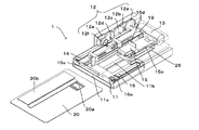
図1は、本発明の実施の形態に係るカードリーダ1の機械構成を示す斜視図である。なお、本実施形態では、情報の読み取り又は書き込みを行うカード状媒体として、表面にIC端子20aが配置されたICカード20を考えるが、本発明を適用するに当たってカード状媒体の種類の如何は問わない。
FIG. 1 is a perspective view showing a mechanical configuration of a card reader 1 according to an embodiment of the present invention. In the present embodiment, an
図1に示すカードリーダ1は、主として、ICカード20を約半分ほど収容する収容部材11と、収容部材11を移動させるための駆動力を伝達する駆動機構12と、を有している。
The card reader 1 shown in FIG. 1 mainly includes a
収容部材11は、カード挿入口11aを有しており、ICカード20が挿入されると、そのICカード20の上面及び下面の少なくとも一部を覆うことができるように、断面がコの字形状となっている。すなわち、収容部材11は、ICカード20が載置される下面板と、下面板に対向してICカード20の上面を覆う上面板とを有しており、上面板の一部には、情報処理用穴11bが形成されている。
The
情報処理用穴11bは、ICカード20表面のIC端子20aに対してIC接点(ブロック)17(図3参照)を当接させるための穴である。すなわち、この情報処理穴11bによって、IC端子20aとIC接点17との当接(接触)が許容されることになる。なお、図1では視認し得ないが、IC接点17は、バネ部材15の裏側(ICカード20と対向する側)に、IC接点保持部材15aによって保持されている。また、バネ部材15のうち折り曲げ部15dは、カードリーダ1の本体に固定されるようになっている。また、フレキシブル基板26は、柔軟な材質で形成されており、その一端は、IC接点17に取り付けられ、その他端は、収容部材11に取り付けられている。
The
収容部材11の上面板のうち、ICカード20の挿入方向から見て左端部分には、ピニオンギア12fと噛み合うラック14が設けられている。そして、アクチュエータ13からの駆動力は、駆動機構12及びラック14を介して、収容部材11に伝達されることになる。
A
駆動機構12は、複数の連動ギア12a〜12e及びピニオンギア12fから構成され、アクチュエータ13における回転軸の回転に伴って、その駆動力をピニオンギア12fまで伝達し得るようになっている。特に、本実施形態では、減速比率を高く設定している。これにより、ICカード20を収容部材11に収容する途中で、収容部材11がずれ動いてしまうのを防ぐことができる。つまり、例えば曲がったICカード20が収容部材11に押し込まれる際、減速比率の高い駆動機構12は、収容部材11が処理位置へ移動するのを防ぐためのストッパーとして機能することができる。
The
なお、収容部材11の内部には、ICカード20の収容完了を検知するとともに、駆動機構12による駆動を開始させるセンサ18(図4参照)が設けられているが、センサ18の機械構成については、図4を用いて後述する。また、本実施形態では、駆動機構12の一例としてラックアンドピニオンについて説明したが、例えば、ピニオンギア12f及びラック14をゴムローラ及びゴムベルトに代えてもよいし、その他、ワイヤーやリードスクリュー,ウォームアンドホイールを用いるなど、アクチュエータ13からの駆動力を収容部材11に伝達し得る機構であれば如何なるものであっても構わない。
Note that a sensor 18 (see FIG. 4) that detects the completion of housing of the
一方で、収容部材11の上面板のうち、ICカード20の挿入方向から見て右端部分には、板バネ16が設けられている。この板バネ16は、ICカード20と当接する当接部16aを有しており、この当接部16aは、収容部材11の下面板に臨んで、ICカード20を下面板に押圧する。これにより、ICカード20を収容部材11に収容された状態に保持できるようになっている。また、収容部材11が一旦移動し始めた後に、ICカード20が収容部材11から抜け出るのを確実に防ぐことができるようになっている。
On the other hand, a
なお、本実施形態では、当接部16aは、下面板に臨んで、ICカード20を下面板がある方向へ押圧することとしたが、逆に、上面板に臨んで、ICカード20を上面板がある方向へ押圧するものであってもよい。また、本実施形態では、収容部材11の上面板のうち、ICカード20の挿入方向から見て右端部分に板バネ16を設けることとしたが、この設置場所についてはどの場所であってもよい。ただし、図1に示すICカード20の表面には、エンボス20bが形成されており、このエンボス20bは、ICカード20の表面のうちICカード20の挿入方向から見て左端部分に形成されるのが一般的である。したがって、本実施形態のように、収容部材11の上面板のうち、ICカード20の挿入方向から見て右端部分に板バネ16を設けることによって、エンボス20bが板バネ16の当接部16aによって傷付くのを防ぐことができる。仮に、板バネ16の当接部16aがエンボス20bに何回も乗り上がると、板バネ16の早期劣化を惹き起こす可能性があるが、このような問題も解消することができる。
In the present embodiment, the
また、本実施形態では、ICカード20を収容部材11に収容された状態に保持する保持部材の一例として、板バネ16を挙げたが、本発明はこれに限られず、例えば、2枚の板バネ16を用いて、ICカード20の厚さ方向(又はこれと直交する方向)に、ICカード20を挟みこんで保持してもよい。
In the present embodiment, the
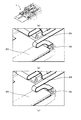
図2は、駆動機構12によって収容部材11が移動する様子を説明するための斜視図である。図3は、駆動機構12によって収容部材11が移動する様子を説明するための断面図である。なお、図2(a)及び図3(a)は、ICカード20がカードリーダ1に挿入される前の状態を示している。また、図3において、一点鎖線Xは、カードリーダ1が組み込まれた機器の外枠(フロントパネル)を示す。すなわち、一点鎖線Xよりもカードリーダ1側は、外部からは視認し得ないようになっている。
FIG. 2 is a perspective view for explaining how the
まず、ICカード20は、カードリーダ1(収容部材11)のカード挿入口11aに差し込まれる。そして、ICカード20が収容部材11の奥まで差し込まれると、ICカード20の差し込みが完了する(図2(b)及び図3(b)参照)。図2(b)及び図3(b)に示す収容部材11の位置は、ICカード20が収容される「収容位置」となる。すなわち、収容部材11の移動が開始される直前の位置である。
First, the
ここで、収容部材11の奥には、駆動機構12による駆動を開始させるセンサ18が設けられている。このセンサ14の機械構成について、図4を用いて詳述する。
Here, a
図4は、収容部材11の奥にセンサ18が設けられている様子を示す図である。なお、図4(b)及び図4(c)は、図4(a)に示す四角枠を拡大した図である。
FIG. 4 is a diagram illustrating a state in which the
収容部材11の奥には、センサ18としてプッシュスイッチが設けられており(図4(b)参照)、このセンサ18にICカード20の挿入方向先端が衝突すると(図4(c)参照)、ICカード収容完了信号がセンサ18からカードリーダ1の情報処理ユニット(図示せず)に送られる。これを受信した情報処理ユニットは、アクチュエータ13に対して駆動信号を送信する。その結果、アクチュエータ13の回転軸が回転し始め、その駆動力が駆動機構12を介して収容部材11に伝達され、収容部材11は移動を開始する。
A push switch is provided as a
なお、本実施形態では、センサ18を収容部材11の奥に配置することとしたが、本発明はこれに限られず、収容部材11のどこに配置しても構わない。また、本実施形態ではセンサ18の一例としてプッシュスイッチを用いたが、その他、発光素子及び受光素子による光スイッチを用いることもできる。
In the present embodiment, the
収容部材11が「収容位置」から移動を開始した後、ICカード20に対して情報の読み取り又は書き込みが行われる位置まで移動したとき、収容部材11の移動は停止する(図2(c)及び図3(c)参照)。図2(c)及び図3(c)に示す収容部材11の位置は、IC接点17を介して、ICカード20に対する情報の読み取り又は書き込みが行われる「処理位置」となる。すなわち、収容部材11の移動が完了した直後の位置を意味する。
After the
ICカード20に対する情報の読み取り又は書き込みが行われるまでについて、より具体的に説明する。まず、ICカード20が収容部材11に挿入され、センサ18によって収容部材11の移動が開始される(図3(b)参照)。その後、収容部材11の先端が、IC接点保持部材15aの度当たり15cに当接する。すると、更に収容部材11が装置奥側(図3中右側)へ移動するとともに、ガイドピン15bによって支持されたIC接点保持部材15a(IC接点17)は、収容部材11に接近する方向に移動する。IC接点保持部材15aは、ストッパー25によって装置奥側への移動を停止する。このとき、IC接点保持部材15aが収容部材11へ接近する方向に移動しているので、IC接点17と、ICカード20のIC端子20aとが接触し、IC通信が行われる。収容部材11が収容位置に戻るときには、逆の動作が行われる。なお、本実施形態では、ガイドピン15bを通じてIC接点保持部材15aをICカード20に接近させることとしたが、本発明はこれに限られず、例えば一又は複数のリンク機構を用いて、IC接点保持部材15aをICカード20に接触或いは接離(離反)させてもよい。
The process until the information is read or written to the
以上説明したように、本実施形態に係るカードリーダ1では、収容部材11は、駆動機構12を介してアクチュエータ13からの駆動力を受け、ICカードの挿入方向又はその反対方向に前後移動(スライド移動)する(図2,図3)。
As described above, in the card reader 1 according to the present embodiment, the
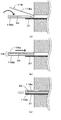
ここで、ICカード20の形態に多少変形が生じている場合を考える。図5は、湾曲しているICカード20がカードリーダ1に挿入される様子を示す断面図である。
Here, consider a case where the
図5(a)に示すように、カードリーダ1に挿入されるICカード20は、湾曲して反った形態となっている。しかし、このような形態のICカード20であっても、収容部材11のカード挿入口11aに差し込まれると、図5(b)に示すように、収容部材11の内部で平らで真っ直ぐな形態に近い形態となる。すなわち、ICカード20の湾曲部分20cは、収容部材11によって、その曲率が小さくなる。そして、この状態で、ICカード20が収容された収容部材11は、上述した所定の位置まで移動する(図5(c))。このように、たとえICカード20の形態に多少変形が生じている場合であっても、カード搬送の際(図5(b)→図5(c))、ICカード20の湾曲部分20cからの圧力が、搬送路ではなく収容部材11に対して加わるようにし、ICカード20の形態の変形分を収容部材11で吸収することによって、カード搬送の負荷が増大するのを防ぐことができる。
As shown in FIG. 5A, the
[実施形態の効果]
以上説明したように、本実施形態に係るカードリーダ1によれば、ICカード20が平らで真っ直ぐの形態であったとしても、或いは、ICカード20が湾曲したり一部が曲がったりした形態であったとしても、収容部材11の移動自体は駆動機構12によって行われるので、ICカード20の形態に起因した搬送負荷のバラツキが生じるのを防ぐことができる。そして、搬送負荷のバラツキを抑えることで、小型かつ安価のアクチュエータを使用して、適切にカード搬送を行うことができる。
[Effect of the embodiment]
As described above, according to the card reader 1 according to this embodiment, even if the
また、収容部材11に収容されたICカード20を、板バネ16の当接部16aによって押さえつけることで、ICカード20が収容部材から抜け出るのを防ぐことができる。
Further, by pressing the
さらに、収容部材11の奥底にはセンサ18が設けられ、ICカード20の収容が完了すると、スムーズに収容部材11の移動へと移行するので、迅速な媒体処理に寄与することができる。
Further, the
なお、本実施形態に係るカードリーダ1では、図1及び図6に示すように、ICカード20を、収容部材11の「処理位置」から「収容位置」向けて強制排出させる排出部材19が設けられている。
In the card reader 1 according to the present embodiment, as shown in FIGS. 1 and 6, a
図6は、排出部材19の強制排出機能について説明するための説明図である。
FIG. 6 is an explanatory diagram for explaining the forced discharge function of the
図6(a)に示すように、排出部材19は、作業者がつまんで引っ張るつまみ部19aと、つまみ部19aと連結し、ICカード20を引っかき出す引っかき部19bと、から構成されている。排出部材19を使用しないときは、図1に示すように、つまみ部19aは、その長手方向がカード挿入方向と直交するようになっている。そして、収容部材11が「処理位置」にある場合において、仮に、何らかのトラブルで収容部材11を「収容位置」に戻せなくなったとき、作業者は、つまみ部19aの一部を起こし(図6(a))、そのままつまみ部19aを手前に引く。そうすると、引っかき部19bの折れ曲がった一端は、ICカード20の端部に引っ掛かっていることから、つまみ部19aを引くにつれてICカード20が強制排出されることになる(図6(b))。
As shown in FIG. 6A, the
このように、ICカード20がカードリーダ1内で詰まってしまった場合であっても、排出部材19を使ってICカード20をカードリーダ1から排出することができる。
Thus, even if the
[変形例]
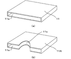
図7は、収容部材11の形態に関する変形例を示す収容部材11Aの概略図である。なお、図7(a)は、上述した実施形態における収容部材11の形態を示している(ただし、上面板の一部に設けられた情報処理穴11bについては、図示を省略している)。
[Modification]
FIG. 7 is a schematic view of the
図7(b)に示すように、収容部材11Aは、カード挿入口11a付近に切欠部11cが設けられている。これにより、カードを収容部材11Aから取り出すときに、取り出しやすくすることができる。
As shown in FIG. 7B, the
図8は、収容部材11の形態に関する変形例を示す収容部材11Bの概略図である。
FIG. 8 is a schematic view of the
図8に示す収容部材11Bは、ICカード20が載置される下面板11Bbと、この下面板11Bbに対向してICカード20の上面を覆う上面板11Baと、を有する箱体であって、上面板11Baは開閉可能となっている。
The
ICカード20を収容部材11Bに収容するときには、上面板11Baを開き、開いた隙間からICカード20を収容する(図8(a)参照)。そして、収容部材11Bは、ベルトやワイヤーなどによって、支持板31の上を摺動しつつ、カードリーダ1の内部に移動していく(図8(b)参照)。収容部材11Bの末端(手前側端)が支持板31の先端部まで移動すると、支持板31は収容部材11Bとともにカードリーダ1の内部に移動していく(図8(c)参照)。
When accommodating the
このように、収容部材の一例として、図8に示すような箱型の収容部材11Bであっても構わない。収容部材11Bであっても、ICカード20の上面及び、下面を覆うことができるので、ICカード20の形態の変形分を吸収することが可能である。なお、収容部材11Bにおいて、収容部材11と同様に、センサ18を取り付けたり(図4参照)、排出部材19を取り付けたり(図6参照)、IC端子20aに対してIC接点17を当接させるための情報処理用穴11bを形成したりしてもよい(図1参照)。
Thus, as an example of the housing member, a box-shaped
本発明に係る媒体処理装置は、カード状媒体の形態に起因した搬送負荷のバラツキが生じるのを防ぐことが可能なものとして有用である。 The medium processing apparatus according to the present invention is useful as a device that can prevent variations in the transport load due to the form of the card-like medium.
1 カードリーダ
11 収容部材
12 駆動機構
12a〜12e 連動ギア
12f ピニオンギア
13 アクチュエータ
14 ラック
15 バネ部材
15a IC接点保持部材
16 板バネ
17 IC接点
18 センサ
19 排出部材
20 ICカード
DESCRIPTION OF SYMBOLS 1
Claims (3)
前記カード状媒体の上面及び下面の少なくとも一部を覆って、前記カード状媒体を収容する収容部材と、
前記収容部材に駆動力を伝達する駆動機構と、
前記カード状媒体表面に配置されたIC端子に当接して、前記カード状媒体に対して情報の読み取り又は書き込みを行うIC接点と、を備え、
前記収容部材は、前記駆動機構によって、前記カード状媒体が収容される収容位置から、前記カード状媒体に対して情報の読み取り又は書き込みが行われる処理位置との間を移動し、
前記収容部材は、前記カード状媒体を当該収容部材に収容された状態に保持する保持部材と、前記カード状媒体を前記処理位置から前記収容位置に向けて強制排出させる排出部材と、を備え、
前記収容部材は、前記カード状媒体が載置される下面板と、当該下面板に対向して前記カード状媒体の上面を覆う上面板と、を有し、
前記保持部材は、前記下面板又は前記上面板のいずれか一方に臨んで、前記カード状媒体を前記下面板又は前記上面板のいずれか他方に押圧する押圧部材であり、
前記カード状媒体表面にはエンボスが形成されており、前記押圧部材は、前記IC端子及び前記エンボスが形成されていないカード状媒体表面に当接する位置に配置されるとともに、前記エンボスが形成されている前記カード状媒体側には前記排出部材が配置されていることを特徴とする媒体処理装置。 In a medium processing apparatus that reads or writes information on a card-like medium,
An accommodation member that covers at least a part of the upper and lower surfaces of the card-like medium and accommodates the card-like medium;
A driving mechanism for transmitting a driving force to the housing member;
An IC contact that abuts on an IC terminal disposed on the surface of the card-like medium and reads or writes information on the card-like medium ,
The storage member is moved by the drive mechanism from a storage position where the card-like medium is stored to a processing position where information is read from or written to the card-like medium ,
The housing member includes a holding member that holds the card-like medium in a state of being housed in the housing member, and a discharge member that forcibly ejects the card-like medium from the processing position toward the housing position,
The housing member includes a lower surface plate on which the card-like medium is placed, and an upper surface plate that faces the lower surface plate and covers the upper surface of the card-like medium,
The holding member is a pressing member that faces either one of the lower surface plate or the upper surface plate and presses the card-like medium against either the lower surface plate or the upper surface plate,
An emboss is formed on the surface of the card-like medium, and the pressing member is disposed at a position that contacts the surface of the card-like medium on which the IC terminal and the emboss are not formed, and the emboss is formed. The medium processing apparatus, wherein the discharge member is arranged on the card-like medium side .
前記カード状媒体は、前記上面板の開閉により前記収容部材に収容されることを特徴とする請求項1記載の媒体処理装置。 The accommodating member is a box having a lower surface plate on which the card-like medium is placed and an upper surface plate that faces the lower surface plate and covers the upper surface of the card-like medium,
The medium processing apparatus according to claim 1, wherein the card-like medium is accommodated in the accommodating member by opening and closing the upper surface plate.
Priority Applications (1)
| Application Number | Priority Date | Filing Date | Title |
|---|---|---|---|
| JP2006209259A JP4867006B2 (en) | 2006-07-31 | 2006-07-31 | Media processing device |
Applications Claiming Priority (1)
| Application Number | Priority Date | Filing Date | Title |
|---|---|---|---|
| JP2006209259A JP4867006B2 (en) | 2006-07-31 | 2006-07-31 | Media processing device |
Publications (2)
| Publication Number | Publication Date |
|---|---|
| JP2008033842A JP2008033842A (en) | 2008-02-14 |
| JP4867006B2 true JP4867006B2 (en) | 2012-02-01 |
Family
ID=39123149
Family Applications (1)
| Application Number | Title | Priority Date | Filing Date |
|---|---|---|---|
| JP2006209259A Expired - Fee Related JP4867006B2 (en) | 2006-07-31 | 2006-07-31 | Media processing device |
Country Status (1)
| Country | Link |
|---|---|
| JP (1) | JP4867006B2 (en) |
Families Citing this family (1)
| Publication number | Priority date | Publication date | Assignee | Title |
|---|---|---|---|---|
| JP2021149359A (en) * | 2020-03-18 | 2021-09-27 | 大日本印刷株式会社 | Housing for reading rfid |
Family Cites Families (5)
| Publication number | Priority date | Publication date | Assignee | Title |
|---|---|---|---|---|
| JPS6292267A (en) * | 1985-10-18 | 1987-04-27 | Canon Inc | Information recording and reproducing device |
| JPS639057A (en) * | 1986-06-30 | 1988-01-14 | Canon Inc | Card placing device |
| JPH11149524A (en) * | 1997-11-14 | 1999-06-02 | Omron Corp | Recording medium reader |
| JP2003045559A (en) * | 2001-07-27 | 2003-02-14 | Alps Electric Co Ltd | Memory card connecting device |
| JP2003150910A (en) * | 2001-11-09 | 2003-05-23 | Canon Inc | Information processing equipment |
-
2006
- 2006-07-31 JP JP2006209259A patent/JP4867006B2/en not_active Expired - Fee Related
Also Published As
| Publication number | Publication date |
|---|---|
| JP2008033842A (en) | 2008-02-14 |
Similar Documents
| Publication | Publication Date | Title |
|---|---|---|
| JP5326011B2 (en) | Card reader | |
| US8998206B2 (en) | Medium feeding direction switching mechanism and medium issuing and collecting device | |
| US9558379B2 (en) | Card reader | |
| CN102089771B (en) | Card processing unit and card issuing device | |
| US8040575B2 (en) | Double side image scanner | |
| JP4867006B2 (en) | Media processing device | |
| US9922213B2 (en) | Card reader | |
| JP4148815B2 (en) | Card insertion device | |
| JP3898173B2 (en) | Card processing device | |
| JP4212996B2 (en) | Card processing device | |
| JP4834368B2 (en) | Card processing device | |
| JP2009053936A (en) | Card reader cleaning structure | |
| JP4441242B2 (en) | Card processing device | |
| JP2012159906A (en) | Card processing device equipped with stored card dispensing mechanism | |
| JP4111230B2 (en) | Card reader insertion slot blocking mechanism | |
| JP5215134B2 (en) | Card reader card transport mechanism and card reader | |
| JP4250065B2 (en) | Card processing device | |
| KR100726811B1 (en) | Duplex image scanner | |
| JPH02281464A (en) | Card reader/writer | |
| JP2005157567A (en) | Card storage device | |
| JP5778556B2 (en) | Card-like medium processing device | |
| JP2005157808A (en) | Card storage device | |
| JP4648795B2 (en) | Card reader | |
| JPH03250389A (en) | Mobile punch type magnetic card reader | |
| JP5314340B2 (en) | Card processing unit and card issuing device |
Legal Events
| Date | Code | Title | Description |
|---|---|---|---|
| A621 | Written request for application examination |
Free format text: JAPANESE INTERMEDIATE CODE: A621 Effective date: 20081027 |
|
| A977 | Report on retrieval |
Free format text: JAPANESE INTERMEDIATE CODE: A971007 Effective date: 20110628 |
|
| A131 | Notification of reasons for refusal |
Free format text: JAPANESE INTERMEDIATE CODE: A131 Effective date: 20110705 |
|
| A521 | Written amendment |
Free format text: JAPANESE INTERMEDIATE CODE: A523 Effective date: 20110905 |
|
| TRDD | Decision of grant or rejection written | ||
| A01 | Written decision to grant a patent or to grant a registration (utility model) |
Free format text: JAPANESE INTERMEDIATE CODE: A01 Effective date: 20111004 |
|
| A01 | Written decision to grant a patent or to grant a registration (utility model) |
Free format text: JAPANESE INTERMEDIATE CODE: A01 |
|
| A61 | First payment of annual fees (during grant procedure) |
Free format text: JAPANESE INTERMEDIATE CODE: A61 Effective date: 20111020 |
|
| R150 | Certificate of patent or registration of utility model |
Free format text: JAPANESE INTERMEDIATE CODE: R150 |
|
| FPAY | Renewal fee payment (event date is renewal date of database) |
Free format text: PAYMENT UNTIL: 20141125 Year of fee payment: 3 |
|
| LAPS | Cancellation because of no payment of annual fees |