JP4863406B2 - Mobile optical communication system and mobile optical communication method - Google Patents
Mobile optical communication system and mobile optical communication method Download PDFInfo
- Publication number
- JP4863406B2 JP4863406B2 JP2008528769A JP2008528769A JP4863406B2 JP 4863406 B2 JP4863406 B2 JP 4863406B2 JP 2008528769 A JP2008528769 A JP 2008528769A JP 2008528769 A JP2008528769 A JP 2008528769A JP 4863406 B2 JP4863406 B2 JP 4863406B2
- Authority
- JP
- Japan
- Prior art keywords
- moving body
- light
- moving
- path
- light receiving
- Prior art date
- Legal status (The legal status is an assumption and is not a legal conclusion. Google has not performed a legal analysis and makes no representation as to the accuracy of the status listed.)
- Expired - Fee Related
Links
Images


Classifications
-
- G—PHYSICS
- G02—OPTICS
- G02B—OPTICAL ELEMENTS, SYSTEMS OR APPARATUS
- G02B6/00—Light guides; Structural details of arrangements comprising light guides and other optical elements, e.g. couplings
- G02B6/24—Coupling light guides
- G02B6/42—Coupling light guides with opto-electronic elements
- G02B6/4201—Packages, e.g. shape, construction, internal or external details
-
- B—PERFORMING OPERATIONS; TRANSPORTING
- B61—RAILWAYS
- B61L—GUIDING RAILWAY TRAFFIC; ENSURING THE SAFETY OF RAILWAY TRAFFIC
- B61L3/00—Devices along the route for controlling devices on the vehicle or vehicle train, e.g. to release brake, to operate a warning signal
- B61L3/02—Devices along the route for controlling devices on the vehicle or vehicle train, e.g. to release brake, to operate a warning signal at selected places along the route, e.g. intermittent control simultaneous mechanical and electrical control
- B61L3/06—Devices along the route for controlling devices on the vehicle or vehicle train, e.g. to release brake, to operate a warning signal at selected places along the route, e.g. intermittent control simultaneous mechanical and electrical control controlling by electromagnetic or particle radiation, e.g. by light beam
- B61L3/065—Devices along the route for controlling devices on the vehicle or vehicle train, e.g. to release brake, to operate a warning signal at selected places along the route, e.g. intermittent control simultaneous mechanical and electrical control controlling by electromagnetic or particle radiation, e.g. by light beam controlling optically
-
- H—ELECTRICITY
- H04—ELECTRIC COMMUNICATION TECHNIQUE
- H04B—TRANSMISSION
- H04B10/00—Transmission systems employing electromagnetic waves other than radio-waves, e.g. infrared, visible or ultraviolet light, or employing corpuscular radiation, e.g. quantum communication
- H04B10/11—Arrangements specific to free-space transmission, i.e. transmission through air or vacuum
- H04B10/112—Line-of-sight transmission over an extended range
- H04B10/1123—Bidirectional transmission
- H04B10/1125—Bidirectional transmission using a single common optical path
-
- G—PHYSICS
- G02—OPTICS
- G02B—OPTICAL ELEMENTS, SYSTEMS OR APPARATUS
- G02B6/00—Light guides; Structural details of arrangements comprising light guides and other optical elements, e.g. couplings
- G02B6/24—Coupling light guides
- G02B6/26—Optical coupling means
- G02B6/28—Optical coupling means having data bus means, i.e. plural waveguides interconnected and providing an inherently bidirectional system by mixing and splitting signals
- G02B6/2804—Optical coupling means having data bus means, i.e. plural waveguides interconnected and providing an inherently bidirectional system by mixing and splitting signals forming multipart couplers without wavelength selective elements, e.g. "T" couplers, star couplers
- G02B6/2852—Optical coupling means having data bus means, i.e. plural waveguides interconnected and providing an inherently bidirectional system by mixing and splitting signals forming multipart couplers without wavelength selective elements, e.g. "T" couplers, star couplers using tapping light guides arranged sidewardly, e.g. in a non-parallel relationship with respect to the bus light guides (light extraction or launching through cladding, with or without surface discontinuities, bent structures)
Landscapes
- Physics & Mathematics (AREA)
- Electromagnetism (AREA)
- Engineering & Computer Science (AREA)
- Mechanical Engineering (AREA)
- Computer Networks & Wireless Communication (AREA)
- Signal Processing (AREA)
- General Physics & Mathematics (AREA)
- Optics & Photonics (AREA)
- Optical Communication System (AREA)
Description
本発明は、移動体光通信システム及び移動体光通信方法に関し、特に光ファイバを用いた移動体光通信システム及び移動体光送信方法に関する。 The present invention relates to a mobile optical communication system and a mobile optical communication method, and more particularly to a mobile optical communication system and a mobile optical transmission method using an optical fiber.
従来の移動体光通信システムとして、漏洩光ファイバを移動体及び移動体の経路に沿って設けたものが知られている。当該移動体光通信システムにおいては、移動体の経路に沿って設けられた漏洩光ファイバから送出された光信号が、移動体の受光部にて受光される。また、移動体に設けられた漏洩光ファイバから送出された光信号が移動体の経路に設けられた受光部にて受光される(例えば、特許文献1参照。)。
しかし、従来の移動体光通信システムでは、漏洩光ファイバの周方向の全方位に、かつ長手方向の全てに渡って光が漏れ出る。そのため、膨大なエネルギーのロスが生じ、それを補うために非常識的な強度の光信号を漏洩光ファイバに送り込み続けなければなかった。そのため列車などの移動体通信に用いることは困難であった。 However, in the conventional mobile optical communication system, light leaks in all directions in the circumferential direction of the leaking optical fiber and in all the longitudinal directions. Therefore, enormous energy loss occurs, and in order to compensate for this, an insane optical signal had to be continuously sent to the leaky optical fiber. Therefore, it was difficult to use for mobile communication such as trains.
すなわち、漏洩光ファイバからは、ファイバ軸全体から常に光が漏洩しているのに対し、移動体に設けられた受光部は、そのわずか一部のみを受光しているに過ぎない。それでもS/Nを確保するためにはある量以上の強度をファイバに送らなければならず、そのために光源が必要とするパワーは、計算上数ワットにものぼる。 That is, light always leaks from the entire fiber axis from the leaking optical fiber, whereas the light receiving portion provided on the moving body receives only a small part thereof. Nevertheless, in order to ensure S / N, a certain amount or more of the intensity must be sent to the fiber, and the power required for the light source is as high as several watts.
例えば、受光部を半導体素子で構成した場合、受光素子の大きさは直径0.1mm程度となる。これは受光素子の大きさが大き過ぎるとブロードバンドに必要なギガビットクラスの通信には使えないためである。この受光素子を移動体に1mおきに設置すると仮定すると、光の利用効率は0.1mm/1mで1万分の1にしかならない。また漏洩率として、100mで光が漏洩し尽くすと仮定し、外乱光の影響を考慮して必要なS/Nを確保するために、受光部に1μWの光量が必要と仮定する。このときの投入パワーは1μW/0.1mm×100mで1Wも必要になる。当然ながら、信号光は100m毎に増幅しなければならない。 For example, when the light receiving unit is formed of a semiconductor element, the size of the light receiving element is about 0.1 mm in diameter. This is because if the size of the light receiving element is too large, it cannot be used for gigabit class communication required for broadband. Assuming that this light receiving element is installed on the moving body every 1 m, the light use efficiency is only 1 / 10,000 at 0.1 mm / 1 m. Further, it is assumed that light leaks out at 100 m as a leakage rate, and in order to secure a necessary S / N in consideration of the influence of disturbance light, it is assumed that a light amount of 1 μW is necessary for the light receiving unit. The input power at this time is 1 μW / 0.1 mm × 100 m, and 1 W is required. Of course, the signal light must be amplified every 100 m.
すなわち、沿線100mに渡り、直径0.1mmの受光素子を乗せた移動体が軌道上のどこを走っていても、受光素子に1μWの到達が必要となる。軌道がほぼ直線と仮定した場合、直径0.1mmの受光素子が軌道に沿って走る面積は、100m×0.1mm、即ち、10−2m2である。この10−2m2の中のどの位置に受光面直径0.1mmすなわち受光面積0.00785×10⁻⁶m2の受光素子があっても、1μWが入射していなければならない。したがって、光ファイバから漏洩された光が広がらないと仮定しても、投入パワーは最低でも、1μW×10−2m2÷0.00785×10⁻⁶m2=1.27Wが必要となる。実際には、光ファイバから漏洩された光は空間的に広がるため、この何倍ものパワーを投入しなければならない。In other words, it is necessary to reach 1 μW to the light receiving element regardless of where the moving body carrying the light receiving element having a diameter of 0.1 mm runs along the track 100 m. Assuming that the track is a substantially straight line, the area where a light receiving element having a diameter of 0.1 mm runs along the track is 100 m × 0.1 mm, that is, 10 −2 m 2 . Even if there is a light receiving element having a light receiving surface diameter of 0.1 mm, that is, a light receiving area of 0.00785 × 10 −6 m 2 at any position in the 10 −2 m 2 , 1 μW must be incident. Therefore, even if it is assumed that the light leaked from the optical fiber does not spread, the input power is required to be at least 1 μW × 10 −2 m 2 ÷ 0.00785 × 10 −6 m 2 = 1.27 W. Actually, since the light leaked from the optical fiber spreads spatially, many times this power must be input.
また、漏洩光の広がりを考慮する必要がある。漏洩光はファイバから放射された瞬間から空間的に広がってしまう。信号光はファイバ中を時系列のパターンとして伝播してくるビット列である。例えば1Gb/s(毎秒1ギガビット)の信号の場合、20〜30cm毎のビット列となっている。これが空間的に広がることは、時間的な歪みを生じることに相当するので、ビットエラーの増大につながることになる。 In addition, it is necessary to consider the spread of leakage light. Leakage light spreads spatially from the moment it is emitted from the fiber. The signal light is a bit string that propagates through the fiber as a time-series pattern. For example, in the case of a signal of 1 Gb / s (1 gigabit per second), the bit string is 20 to 30 cm. This spatial expansion corresponds to the occurrence of temporal distortion, leading to an increase in bit errors.
そこで本発明は、効率的に光を送受信することによりエネルギーロスを減少させることが可能な移動体光通信システム及び移動体光通信方法を提供することを目的とする。 Then, an object of this invention is to provide the mobile optical communication system and the mobile optical communication method which can reduce an energy loss by transmitting / receiving light efficiently.
上記目的を達成するために、本発明は、複数の移動体側受光手段を有する移動体と、該移動体の移動経路に沿って敷設され、該複数の移動体側受光手段が受光可能な光を送出する複数のファイバ側光送出手段を有する光ファイバケーブルと、を備えた移動体光通信システムであって、該複数のファイバ側光送出手段は該移動体の移動方向における長さ以下の間隔で並設され、該移動体側受光手段は、該移動体の移動方向に沿って、該ファイバ側光送出手段から該移動体に照射された光像の該移動体の移動方向における長さ以下の所定間隔で並設されており、該光ファイバケーブルは、コアと該コアよりも屈折率が低く該コアに外接したクラッドと、該コアに接して形成され屈折率が該コアの屈折率より低く、かつ該クラッドの屈折率より高い光漏洩部であって、該移動体の移動方向に断続的に複数設けられた光漏洩部とを有する漏洩光ファイバケーブルであり、該光漏洩部は該ファイバ側光送出手段として機能することを特徴とする移動体光通信システムを提供している。
In order to achieve the above object, the present invention provides a moving body having a plurality of moving body side light receiving means and light that is laid along the moving path of the moving body and that can be received by the plurality of moving body side light receiving means. An optical fiber cable having a plurality of fiber-side light sending means, wherein the plurality of fiber-side light sending means are arranged at intervals equal to or less than the length in the moving direction of the moving body. The moving body-side light receiving means is provided at a predetermined interval along the moving direction of the moving body, which is equal to or shorter than the length in the moving direction of the moving body of the optical image irradiated to the moving body from the fiber-side light sending means. The optical fiber cable includes a core, a cladding having a lower refractive index than the core, and a cladding circumscribing the core; a refractive index formed in contact with the core; the refractive index being lower than the refractive index of the core; and Higher than the refractive index of the cladding A leakage optical fiber cable having a leakage portion, and a plurality of light leakage portions intermittently provided in the moving direction of the moving body, wherein the light leakage portion functions as the fiber-side light transmission means. A mobile optical communication system is provided.
ここで、該光漏洩部は該光ファイバケーブルの周方向の一部に設けられていることが好ましい。さらに、該複数の光漏洩部のうち、該移動体の移動方向下流側の該光漏洩部の方が上流側の該光漏洩部より光の漏洩率が高いことが好ましい。さらに、該光漏洩部の長手方向の長さは、伝播する光信号の1ビットに相当する空間的な長さ以下であることが好ましい。あるいは、該ファイバ側光送出手段は光送信装置であることが好ましい。
Here, it is preferable that the light leakage mode portion is provided on a part of circumferential direction of the optical fiber cable. Furthermore, it is preferable that, among the plurality of light leakage portions, the light leakage portion on the downstream side in the moving direction of the moving body has a higher light leakage rate than the light leakage portion on the upstream side. Furthermore, it is preferable that the length of the light leakage portion in the longitudinal direction is not more than a spatial length corresponding to one bit of the propagating optical signal. Alternatively, it is preferable that the fiber side light transmission means is an optical transmission device.
また、本発明は、複数の移動体側受光手段を有する移動体と、該移動体の移動経路に沿って敷設され、該複数の移動体側受光手段が受光可能な光を送出する複数のファイバ側光送出手段を有する光ファイバケーブルと、を備えた移動体光通信システムであって、該複数のファイバ側光送出手段は該移動体の移動方向における長さ以下の間隔で並設され、該移動体側受光手段は、該移動体の移動方向に沿って、該ファイバ側光送出手段から該移動体に照射された光像の該移動体の移動方向における長さ以下の所定間隔で並設されており、該移動体は、それぞれ該複数の移動体側受光手段を有する複数の移動体を備え、該移動経路には、1本の経路が複数の分岐経路に分岐する分岐位置と、該複数の分岐経路が再び1本の経路に合流する合流位置が設けられ、該移動経路は、各区間に該複数の移動体のうち1台のみが存在するように設定される複数の区間を有し、各分岐経路は、該複数の区間のうちの一区間として機能し、各区間に1対1で対応するように複数の基地局が設けられ、各区間における該複数のファイバ側光送出手段は対応する該基地局に接続されていることを特徴とする移動体光通信システムを提供している。
The present invention also provides a moving body having a plurality of moving body side light receiving means, and a plurality of fiber side lights that are laid along the moving path of the moving body and transmit light that can be received by the plurality of moving body side light receiving means. An optical fiber cable having a sending means, wherein the plurality of fiber-side light sending means are arranged in parallel at intervals equal to or less than the length in the moving direction of the moving body. The light receiving means are arranged in parallel along the moving direction of the moving body at predetermined intervals equal to or less than the length in the moving direction of the moving body of the optical image irradiated to the moving body from the fiber side light sending means. , the moving body is provided with a plurality of mobile bodies each having a movable body side light-receiving means of the plurality of, in the movement path, a branching position where one path is branched into a plurality of branch paths, the plurality of branch path Where merging again into one path The moving path has a plurality of sections set so that only one of the plurality of moving bodies exists in each section, and each branch path is one section of the plurality of sections. functions as a plurality of base stations are provided so as to correspond to one-to-one to each section, the fiber side light delivery means of said plurality of in each section is characterized by being connected to a corresponding base station A mobile optical communication system is provided.
また、本発明は、複数の移動体側光送出手段を有する移動体と、該移動体の移動経路に沿って敷設され、該複数の移動体側光送出手段から送出された光を受光可能な複数のファイバ側受光手段を有する光ファイバケーブルと、を備えた移動体光通信システムであって、該複数の移動体側光送出手段は移動体の移動方向に沿って配置され、該移動体が該移動経路に沿って移動したときに、任意の隣接する2つの移動体側光送出手段から該移動経路に向けて照射されたそれぞれの光像は重なる領域を有し、該重なる領域は、各ファイバ側受光手段を通過するように配置されており、該複数のファイバ側受光手段は該移動体の移動方向における長さ以下の間隔で並設されており、任意の隣接する2つの移動体側光送出手段から送出される光の波長は互いに異なっていることを特徴とする移動体光通信システムを提供している。
In addition, the present invention provides a moving body having a plurality of moving body side light transmitting means, and a plurality of light bodies that are laid along the moving path of the moving body and are capable of receiving light transmitted from the plurality of moving body side light transmitting means. An optical fiber cable having a fiber-side light receiving means, wherein the plurality of mobile-side light transmitting means are arranged along a moving direction of the moving body, and the moving body is connected to the moving path. Each of the optical images emitted from any two adjacent moving body side light transmitting means toward the moving path has an overlapping area, and the overlapping area is defined by each fiber side light receiving means. The plurality of fiber side light receiving means are arranged in parallel at intervals equal to or less than the length in the moving direction of the moving body, and are sent from any two adjacent moving body side light sending means. The wavelength of the light It provides a mobile optical communication system, characterized in that different you are.
さらに、該移動体は、それぞれ該複数の移動体側光送出手段を有する複数の移動体を備え、該移動経路には、1本の経路が複数の分岐経路に分岐する分岐位置と、該複数の分岐経路が再び1本の経路に合流する合流位置が設けられ、該移動経路は、各区間に該複数の移動体のうち1台のみが存在するように設定される複数の区間を有し、各分岐経路は、該複数の区間のうちの一区間として機能し、各区間に1対1で対応するように複数の基地局が設けられ、各区間における該複数のファイバ側受光手段は対応する該基地局に接続されていることが好ましい。 Further, the moving body includes a plurality of moving bodies each having the plurality of moving body side light transmission means, and the moving path includes a branch position where one path branches into a plurality of branch paths, and the plurality of the moving bodies. A joining position where the branching route joins again one route is provided, and the moving route has a plurality of sections set so that only one of the plurality of moving bodies exists in each section, Each branch path functions as one section of the plurality of sections, and a plurality of base stations are provided so as to correspond to each section on a one-to-one basis, and the plurality of fiber side light receiving means in each section correspond to each branch path. It is preferable to be connected to the base station.
さらに本発明は、複数の移動体側受光手段と複数の移動体側光送出手段とを有する移動体と、該移動体の移動経路に沿って敷設され、該複数の移動体側受光手段が受光可能な光を送出する複数のファイバ側光送出手段を有する第1の光ファイバケーブルと、該複数の移動体側光送出手段から送出された光を受光可能な複数のファイバ側受光手段を有する第2の光ファイバケーブルと、を備えた移動体光通信システムであって、該複数のファイバ側光送出手段は該移動体の移動方向における長さ以下の間隔で並設され、該移動体側受光手段は、該移動体の移動方向に沿って、該ファイバ側光送出手段から該移動体に照射された光像の該移動体の移動方向における長さ以下の所定間隔で並設されており、該移動体が該移動経路に沿って移動したときに、任意の隣接する2つの移動体側光送出手段から該移動経路に向けて照射されたそれぞれの光像は重なる領域を有し、該重なる領域は、各ファイバ側受光手段を通過するように配置されており、該複数のファイバ側受光手段は該移動体の移動方向における長さ以下の間隔で並設されており、任意の隣接する2つの移動体側光送出手段から送出される光の波長は、互いに異なり、且つファイバ側光送出手段から送出される光の波長とも異なっていることを特徴とする移動体光通信システムを提供している。
Furthermore, the present invention provides a moving body having a plurality of moving body side light receiving means and a plurality of moving body side light transmitting means, and light laid along the moving path of the moving body and capable of receiving light by the plurality of moving body side light receiving means. A first optical fiber cable having a plurality of fiber side light transmitting means for transmitting light, and a second optical fiber having a plurality of fiber side light receiving means capable of receiving light transmitted from the plurality of mobile body side light transmitting means A plurality of fiber-side light transmitting means arranged in parallel at intervals equal to or less than a length in a moving direction of the moving body, and the moving-side light receiving means Along the moving direction of the body, a light image irradiated to the moving body from the fiber side light transmitting means is arranged in parallel at a predetermined interval equal to or less than the length in the moving direction of the moving body, and the moving body is If you move along the movement path In addition, the respective light images emitted from any two adjacent moving body side light transmitting means toward the moving path have overlapping areas, and the overlapping areas are arranged so as to pass through the respective fiber side light receiving means. The plurality of fiber side light receiving means are arranged in parallel at intervals equal to or less than the length in the moving direction of the moving body, and the wavelength of light transmitted from any two adjacent moving body side light transmitting means is There is provided a mobile optical communication system characterized by being different from each other and having different wavelengths of light transmitted from the fiber side light transmitting means .
ここで、該第1の光ファイバケーブルは、コアと、該コアよりも屈折率が低く該コアに外接したクラッドと、該コアに接して形成され屈折率が該コアの屈折率より低く、かつ該クラッドの屈折率より高い光漏洩部であって該移動体の移動方向に断続的に複数設けられた光漏洩部とを有する漏洩光ファイバケーブルであり、該光漏洩部は該ファイバ側光送出手段としているのが好ましい。また、該光漏洩部は該第1の光ファイバケーブルの周方向の一部に設けられていることが好ましい。さらに、該複数の光漏洩部のうち、該移動体の移動方向下流側の該光漏洩部の方が上流側の該光漏洩部より光の漏洩率が高いことが好ましい。あるいは、該ファイバ側光送出手段は光送信装置であることが好ましい。 Here, the first optical fiber cable includes a core, a clad having a lower refractive index than the core and circumscribing the core, a refractive index formed in contact with the core and lower than a refractive index of the core, and A leakage optical fiber cable having a light leakage portion higher than the refractive index of the cladding and a plurality of light leakage portions intermittently provided in a moving direction of the moving body, the light leakage portion being a fiber-side light transmitting portion Preferably it is a means. Further, it is preferable that the light leakage portion is provided in a part of the circumferential direction of the first optical fiber cable. Furthermore, it is preferable that, among the plurality of light leakage portions, the light leakage portion on the downstream side in the moving direction of the moving body has a higher light leakage rate than the light leakage portion on the upstream side. Alternatively, it is preferable that the fiber side light transmission means is an optical transmission device.
また、該移動体は、それぞれ該複数の移動体側光送出手段と該複数の移動体側受光手段とを有する複数の移動体を備え、該移動経路には、1本の経路が複数の分岐経路に分岐する分岐位置と、該複数の分岐経路が再び1本の経路に合流する合流位置が設けられ、該移動経路は、各区間に該複数の移動体のうち1台のみが存在するように設定される複数の区間を有し、各分岐経路は、該複数の区間のうちの一区間として機能し、各区間に1対1で対応するように複数の基地局が設けられ、各区間における該複数のファイバ側光送出手段及び複数のファイバ側受光手段は対応する該基地局に接続されていることが好ましい。 In addition, the moving body includes a plurality of moving bodies each having the plurality of moving body side light transmitting means and the plurality of moving body side light receiving means, and one path is divided into a plurality of branch paths. A branching position for branching and a joining position where the plurality of branching paths join again to one path are provided, and the moving path is set so that only one of the plurality of moving bodies exists in each section. Each branch path functions as one section of the plurality of sections, and a plurality of base stations are provided so as to correspond to each section on a one-to-one basis. The plurality of fiber side light transmitting means and the plurality of fiber side light receiving means are preferably connected to the corresponding base station.
また、本発明は、移動体の移動方向に沿って該移動体に設けられた複数の送出位置から光を送出し、該送出された光を、該移動体の経路上に設けられた複数の受光位置のうち少なくとも一つの受光位置で受光し、該移動体の経路上の該複数の受光位置のうち少なくとも一つの受光位置で受光された光を、該移動体の経路に沿って伝達する移動体光通信方法において、該移動体が該移動体の経路に沿って移動したときに、任意の隣接する2つの移動体側送出位置から該移動体の経路に向けて照射されたそれぞれの光像は重なる領域を有し、該重なる領域は、該移動体の経路上の各受光位置を通過するように配置されており、該経路上の該複数の受光位置は該移動体の移動方向における長さ以下の間隔で並設されており、任意の隣接する2つの移動体側送出位置から送出される光の波長は互いに異なっていることを特徴とする移動体光通信方法を提供している。
Further, the present invention sends light from a plurality of transmission positions provided on the moving body along the moving direction of the moving body, and sends the transmitted light to a plurality of paths provided on the path of the moving body. Movement that receives light at at least one light receiving position among light receiving positions and transmits light received at at least one light receiving position among the plurality of light receiving positions on the path of the moving body along the path of the moving body In the body optical communication method, when the mobile body moves along the path of the mobile body, each optical image irradiated toward the path of the mobile body from any two adjacent mobile-side transmission positions is The overlapping area is disposed so as to pass through each light receiving position on the path of the moving body, and the plurality of light receiving positions on the path have a length in the moving direction of the moving body. It is juxtaposed at intervals of less than, any two adjacent TsunoUtsuri Wavelength of light transmitted from side delivery position provides a mobile optical communication method characterized in that are different from each other.
また、本発明は、移動体の経路に沿って光を伝達し、該移動体の経路上に設けられた複数の送出位置から、該移動体の経路に沿って伝達された光を該移動体に向けて送出し、該移動体に向けて送出された光を、該移動体の複数の受光位置のうち少なくとも一つの受光位置で受光し、該移動体の移動方向に沿って該移動体に設けられた複数の送出位置から光を送出し、該送出された光を、該移動体の経路上に設けられた複数の受光位置のうち少なくとも一つの受光位置で受光し、該移動体の経路上の該複数の受光位置のうち少なくとも一つの受光位置で受光された光を、該移動体の経路に沿って伝達する移動体光通信方法において、該経路上の該複数の送出位置は、該移動体の移動方向における長さ以下の間隔で設けられ、該移動体の該複数の受光位置は、該移動体の移動方向に沿って、該経路上の該複数の送出位置から該移動体に照射された光像の該移動体の移動方向における長さ以下の所定間隔で並設され、該移動体が該移動体の経路に沿って移動したときに、任意の隣接する2つの移動体側送出位置から該移動体の経路に向けて照射されたそれぞれの光像は重なる領域を有し、該重なる領域は、該移動体の経路上の各受光位置を通過するように配置されており、該経路上の該複数の受光位置は該移動体の移動方向における長さ以下の間隔で並設されており、任意の隣接する2つの移動体側送出位置から送出される光の波長は、互いに異なり、且つ経路上の送出位置から送出される光の波長とも異なっていることを特徴とする移動体光通信方法を提供している。
The present invention also transmits light along the path of the moving body, and transmits the light transmitted along the path of the moving body from a plurality of transmission positions provided on the path of the moving body. The light transmitted toward the moving body is received at at least one light receiving position among the plurality of light receiving positions of the moving body, and is transmitted to the moving body along the moving direction of the moving body. Light is transmitted from a plurality of transmission positions provided, and the transmitted light is received at at least one light reception position among a plurality of light reception positions provided on the path of the mobile body, and the path of the mobile body In the mobile optical communication method for transmitting light received at at least one light receiving position among the plurality of light receiving positions on the mobile body along the path of the mobile body, the plurality of transmission positions on the path are Provided at intervals equal to or less than the length in the moving direction of the moving body, The light positions are arranged in parallel along the moving direction of the moving body at predetermined intervals equal to or less than the length in the moving direction of the moving body of the light image irradiated to the moving body from the plurality of sending positions on the path. When the moving body moves along the path of the moving body, the respective light images irradiated toward the path of the moving body from any two adjacent mobile-side transmission positions have overlapping regions. The overlapping region is arranged so as to pass through each light receiving position on the path of the moving body, and the plurality of light receiving positions on the path are at intervals equal to or shorter than the length in the moving direction of the moving body. The wavelengths of light transmitted from any two adjacent mobile-side transmission positions are different from each other, and are different from the wavelengths of light transmitted from the transmission positions on the path. A mobile optical communication method is provided.
請求項1記載の移動体光通信システムによれば、複数のファイバ側光送出手段は移動体の移動方向における長さ以下の間隔で並設され、移動体側受光手段は、移動体の移動方向に沿って、ファイバ側光送出手段から移動体に照射された光像の移動体の移動方向における長さ以下の所定間隔で並設されている。このため、移動体が移動体の経路上のいずれの地点にいても、ファイバ側光送出手段から送出された光を複数の移動体側受光手段のうち少なくとも一つの移動体側受光手段で確実に受信することができる。よって、シームレスなダウンリンクが達成される。また、光ファイバケーブルは漏洩光ファイバケーブルであるため、装置の設置が容易になり、装置の設置にかかる費用を抑えられる。
According to the mobile optical communication system of the first aspect, the plurality of fiber-side light transmitting means are arranged in parallel at intervals equal to or less than the length in the moving direction of the moving body, and the moving body-side light receiving means is arranged in the moving direction of the moving body. Along with this, the optical images irradiated from the fiber-side light transmission means are arranged in parallel at a predetermined interval equal to or less than the length in the moving direction of the moving body. Therefore, regardless of the position of the moving body on the path of the moving body, the light transmitted from the fiber-side light transmitting means is reliably received by at least one moving body-side light receiving means among the plurality of moving body-side light receiving means. be able to. Thus, seamless downlink is achieved. In addition, since the optical fiber cable is a leaky optical fiber cable, the installation of the apparatus becomes easy, and the cost required for the installation of the apparatus can be suppressed.
請求項2記載の移動体光通信システムによれば、光漏洩部は光ファイバケーブルの周方向の一部に設けられている。このため光漏洩部から漏れ出る光の量を周方向に関して限定することができる。これにより、光の無駄な漏洩を減らすことが出来、長距離に渡って光信号を伝播させることができる。
According to the mobile optical communication system of the second aspect , the light leakage portion is provided in a part of the optical fiber cable in the circumferential direction. For this reason, the amount of light leaking from the light leakage portion can be limited in the circumferential direction. Thereby, useless leakage of light can be reduced, and an optical signal can be propagated over a long distance.
請求項3記載の移動体光通信システムによれば、移動体の移動方向下流側の光漏洩部の方が上流側の光漏洩部より光の漏洩率が高くなっている。このため各光漏洩部から漏れ出る光の量を一定にすることができる。よって、安定した光通信が達成される。
According to the mobile optical communication system of the third aspect, the light leakage rate at the downstream side in the moving direction of the mobile body is higher than that at the upstream side. For this reason, the amount of light leaking from each light leakage portion can be made constant. Therefore, stable optical communication is achieved.
請求項4記載の移動体光通信システムによれば、光漏洩部の長手方向の長さは、伝播する光信号の1ビットに相当する空間的な長さ以下であるため、複数個のビット信号が一度に空間に放射されることはない。よって、信号の歪みのない安定したダウンリンクが達成できる。
According to the mobile optical communication system of
請求項5記載の移動体光通信システムによれば、ファイバ側光送出手段は光送信装置であるため、エラーの少ない精度のよい光通信が達成される。
According to the mobile optical communication system of the fifth aspect , since the fiber-side optical transmission means is an optical transmission device, optical communication with high accuracy with few errors can be achieved.
請求項6記載の移動体光通信システムによれば移動経路には、移動体は、それぞれ複数の移動体側受光手段を有する複数の移動体を備えている。1本の経路が複数の分岐経路に分岐する分岐位置と、複数の分岐経路が再び1本の経路に合流する合流位置が設けられている。そして、移動経路は、各区間に複数の移動体のうち1台のみが存在するように設定される複数の区間を有している。また、各分岐経路は、該複数の区間のうちの一区間として機能する。さらに、各区間に1対1で対応するように複数の基地局が設けられている。各区間における複数のファイバ側光送出手段は対応する基地局に接続されている。このため、分岐経路を有する移動経路において、複数の車両の間で混線がないダウンリンクを行うことができる。また、複数の車両が独立してシームレスなダウンリンクを行うことができる。
According to the mobile optical communication system of the sixth aspect , the moving body includes a plurality of moving bodies each having a plurality of moving body side light receiving means on the moving path. A branch position where one path branches into a plurality of branch paths, and a merge position where a plurality of branch paths merge into one path again are provided. The movement route has a plurality of sections set so that only one of the plurality of moving bodies exists in each section. Each branch path functions as one section of the plurality of sections. Further, a plurality of base stations are provided so as to correspond to each section on a one-to-one basis. A plurality of fiber-side light transmission means in each section are connected to a corresponding base station. For this reason, in a moving route having a branch route, it is possible to perform downlink without crosstalk between a plurality of vehicles. In addition, a plurality of vehicles can independently perform a seamless downlink.
請求項7記載の移動体光通信システムによれば、複数の移動体側光送出手段は移動体の移動方向に沿って配置されている。移動体が移動経路に沿って移動したときに、任意の隣接する2つの移動体側光送出手段から移動経路に向けて照射されたそれぞれの光像は重なる領域を有し、重なる領域は、各ファイバ側受光手段を通過するように配置されている。複数のファイバ側受光手段は移動体の移動方向における長さ以下の間隔で並設されている。このため、移動体が移動体の経路上のいずれの地点にいても、複数の移動体側光送出手段のうち少なくとも一つの移動体側光送出手段から送出された光がファイバ側受光手段に受信される。よって、シームレスなアップリンクを達成できる。また、任意の隣接する2つの移動体側光送出手段から送出される光の波長は互いに異なっている。このため、任意の隣接する2つの移動体側光送出手段から照射される光による干渉ノイズを避けることができる。よって、ファイバ側受光手段は確実に移動体側光送出手段から送出される光を受光する。従って、混線のないアップリンクを達成できる。
According to the mobile optical communication system of the seventh aspect , the plurality of mobile-side light transmitting means are arranged along the moving direction of the mobile body. When the moving body moves along the moving path, the respective optical images irradiated toward the moving path from any two adjacent moving body-side light transmitting means have overlapping areas, and the overlapping areas correspond to the respective fibers. It arrange | positions so that a side light-receiving means may be passed. The plurality of fiber side light receiving means are arranged in parallel at intervals equal to or less than the length in the moving direction of the moving body. For this reason, the light transmitted from at least one moving body side light transmitting means among the plurality of moving body side light transmitting means is received by the fiber side light receiving means regardless of the position of the moving body on the path of the moving body. . Thus, a seamless uplink can be achieved. Further, the wavelengths of light transmitted from any two adjacent mobile-side light transmitting means are different from each other. For this reason, it is possible to avoid interference noise caused by light emitted from any two adjacent mobile-side light transmission means. Therefore, the fiber side light receiving means reliably receives the light sent from the moving body side light sending means. Therefore, an uplink without crossing can be achieved.
請求項8記載の移動体光通信システムによれば移動経路には、移動体は、それぞれ複数の移動体側光送出手段を有する複数の移動体を備えている。1本の経路が複数の分岐経路に分岐する分岐位置と、複数の分岐経路が再び1本の経路に合流する合流位置が設けられている。そして、移動経路は、各区間に複数の移動体のうち1台のみが存在するように設定される複数の区間を有している。また、各分岐経路は、該複数の区間のうちの一区間として機能する。さらに、各区間に1対1で対応するように複数の基地局が設けられている。各区間における複数のファイバ側光受光手段は対応する基地局に接続されている。このため、分岐経路を有する移動経路において、複数の車両の間で混線がないアップリンクを行うことができる。また、複数の車両が独立してシームレスなアップリンクを行うことができる。
According to the mobile optical communication system of the eighth aspect , the mobile body includes a plurality of mobile bodies each having a plurality of mobile body side light transmitting means on the movement path. A branch position where one path branches into a plurality of branch paths, and a merge position where a plurality of branch paths merge into one path again are provided. The movement route has a plurality of sections set so that only one of the plurality of moving bodies exists in each section. Each branch path functions as one section of the plurality of sections. Further, a plurality of base stations are provided so as to correspond to each section on a one-to-one basis. A plurality of fiber side light receiving means in each section are connected to the corresponding base station. For this reason, in a moving route having a branch route, it is possible to perform an uplink without crosstalk between a plurality of vehicles. In addition, a plurality of vehicles can independently perform a seamless uplink.
請求項9記載の移動体光通信システムによれば、複数のファイバ側光送出手段は移動体の移動方向における長さ以下の間隔で並設されている。移動体側受光手段は、移動体の移動方向に沿って、ファイバ側光送出手段から移動体に照射された光像の移動体の移動方向における長さ以下の所定間隔で並設されている。さらに、移動体が移動経路に沿って移動したときに、任意の隣接する2つの移動体側光送出手段から移動経路に向けて照射されたそれぞれの光像は重なる領域を有し、重なる領域は、各ファイバ側受光手段を通過するように配置されている。複数のファイバ側受光手段は移動体の移動方向における長さ以下の間隔で並設されている。このため、移動体が移動体の経路上のいずれの地点にいても、光送出手段から送出された光を複数の移動体側受光手段のうち少なくとも一つの移動体側受光手段で確実に受信することができる。また、移動体が移動体の経路上のいずれの地点にいても、複数の移動体側光送出手段のうち少なくとも一つの移動体側光送出手段から送出された光がファイバ側受光手段に受信される。従って、シームレスな双方向通信を達成できる。また、任意の隣接する2つの移動体側光送出手段から送出される光の波長は、互いに異なり、且つファイバ側光送出手段から送出される光の波長とも異なっている。このため、任意の隣接する2つの移動体側光送出手段から照射される光及びファイバ側光送出手段から送出される光による干渉ノイズを避けることができる。よって、ファイバ側受光手段は確実に移動体側光送出手段から送出される光を受光し、移動体側受光手段はファイバ側光送出手段から送出される光を確実に受光することができる。従って、混線のない双方向通信を達成できる。
According to the mobile optical communication system of the ninth aspect , the plurality of fiber-side light transmitting means are arranged in parallel at intervals equal to or less than the length in the moving direction of the mobile body. The moving body side light receiving means are arranged in parallel along the moving direction of the moving body at predetermined intervals equal to or less than the length in the moving direction of the moving body of the optical image irradiated from the fiber side light sending means to the moving body. Furthermore, when the moving body moves along the moving path, the respective light images emitted toward the moving path from any two adjacent moving body side light transmitting means have overlapping areas, and the overlapping areas are: It arrange | positions so that each fiber side light-receiving means may be passed. The plurality of fiber side light receiving means are arranged in parallel at intervals equal to or less than the length in the moving direction of the moving body. For this reason, the light transmitted from the light transmitting means can be reliably received by at least one moving body side light receiving means among the plurality of moving body side light receiving means, regardless of the position of the moving body on the path of the moving body. it can. In addition, regardless of the position of the moving body on the path of the moving body, the light transmitted from at least one of the plurality of moving body side light transmitting means is received by the fiber side light receiving means. Therefore, seamless bidirectional communication can be achieved. In addition, the wavelengths of light transmitted from any two adjacent mobile-side light transmission means are different from each other, and are different from the wavelengths of light transmitted from the fiber-side light transmission means. For this reason, it is possible to avoid interference noise caused by light emitted from any two adjacent mobile-side light sending means and light sent from the fiber-side light sending means. Therefore, the fiber side light receiving means can reliably receive the light transmitted from the moving body side light sending means, and the moving body side light receiving means can surely receive the light sent from the fiber side light sending means. Therefore, bidirectional communication without crossing can be achieved.
請求項10記載の移動体光通信システムによれば、光ファイバケーブルは漏洩光ファイバケーブルであるため、装置の設置が容易になり、装置の設置にかかる費用を抑えられる。
According to the mobile optical communication system of the tenth aspect , since the optical fiber cable is a leaky optical fiber cable, the installation of the apparatus is facilitated, and the cost required for the installation of the apparatus can be suppressed.
請求項11記載の移動体光通信システムによれば、光漏洩部は光ファイバケーブルの周方向の一部に設けられている。このため光漏洩部から漏れ出る光の量を周方向に関して限定することができる。これにより、光の無駄な漏洩を減らすことが出来、長距離に渡って光信号を伝播させることができる。
According to the mobile optical communication system of the eleventh aspect , the light leakage part is provided in a part of the optical fiber cable in the circumferential direction. For this reason, the amount of light leaking from the light leakage portion can be limited in the circumferential direction. Thereby, useless leakage of light can be reduced, and an optical signal can be propagated over a long distance.
請求項12記載の移動体光通信システムによれば、移動体の移動方向下流側の光漏洩部の方が上流側の光漏洩部より光の漏洩率が高くなっている。このため各光漏洩部から漏れ出る光の量を一定にすることができる。よって、安定した光通信が達成される。
According to the mobile optical communication system of the twelfth aspect, the light leakage rate at the downstream side in the moving direction of the mobile body is higher than that at the upstream side. For this reason, the amount of light leaking from each light leakage portion can be made constant. Therefore, stable optical communication is achieved.
請求項13記載の移動体光通信システムによれば、ファイバ側光送出手段は光送信装置であるため、エラーの少ない精度のよい光通信が達成される。
According to the mobile optical communication system of the thirteenth aspect , since the fiber side optical transmission means is an optical transmission apparatus, optical communication with high accuracy with few errors is achieved.
請求項14記載の移動体光通信システムによれば移動経路には、移動体は、それぞれ複数の移動体側光送出手段と複数の移動体側受光手段とを有する複数の移動体を備えている。1本の経路が複数の分岐経路に分岐する分岐位置と、複数の分岐経路が再び1本の経路に合流する合流位置が設けられている。そして、移動経路は、各区間に複数の移動体のうち1台のみが存在するように設定される複数の区間を有している。また、各分岐経路は、該複数の区間のうちの一区間として機能する。さらに、各区間に1対1で対応するように複数の基地局が設けられている。各区間における複数のファイバ側光送出手段および複数のファイバ側光受光手段は対応する基地局に接続されている。このため、分岐経路を有する移動経路において、複数の車両の間で混線がない双方向通信を行うことができる。また、複数の車両が独立してシームレスな双方向通信を行うことができる。
According to the mobile optical communication system of the fourteenth aspect, the moving path includes a plurality of moving bodies each having a plurality of moving body side light transmitting means and a plurality of moving body side light receiving means. A branch position where one path branches into a plurality of branch paths, and a merge position where a plurality of branch paths merge into one path again are provided. The movement route has a plurality of sections set so that only one of the plurality of moving bodies exists in each section. Each branch path functions as one section of the plurality of sections. Further, a plurality of base stations are provided so as to correspond to each section on a one-to-one basis. The plurality of fiber side light transmitting means and the plurality of fiber side light receiving means in each section are connected to the corresponding base station. For this reason, bi-directional communication without crosstalk can be performed between a plurality of vehicles on a moving route having a branch route. Moreover, a plurality of vehicles can independently perform seamless bidirectional communication.
請求項15記載の移動体光通信方法によれば、移動体が移動体の経路に沿って移動したときに、任意の隣接する2つの移動体側光送出位置から移動体の経路に向けて照射されたそれぞれの光像は重なる領域を有し、重なる領域は、移動体の経路上の各受光位置を通過するように配置されている。経路上の複数の受光位置は移動体の移動方向における長さ以下の間隔で並設されている。このため、移動体が移動体の経路上のいずれの地点にいても、複数の移動体の光送出位置のうち少なくとも一つの移動体の光送出位置から送出された光が経路上の受光位置に受信される。よって、シームレスなアップリンクが達成される。また、任意の隣接する2つの移動体側光送出位置から送出される光の波長は互いに異なっている。このため、任意の隣接する2つの移動体の送出位置から照射される光による干渉ノイズを避けることができ、経路上の受光位置は確実に移動体の送出位置から送出される光を受光する。従って、混線のないアップリンクを達成できる。
According to the mobile optical communication method according to claim 15 , when the mobile body moves along the path of the mobile body, irradiation is performed toward the path of the mobile body from any two adjacent mobile body side light transmission positions. Each optical image has an overlapping region, and the overlapping region is arranged so as to pass through each light receiving position on the path of the moving body. The plurality of light receiving positions on the path are arranged in parallel at intervals equal to or shorter than the length in the moving direction of the moving body. For this reason, regardless of where the moving body is located on the path of the moving body, light transmitted from the light transmitting position of at least one moving body among the light transmitting positions of the plurality of moving bodies becomes the light receiving position on the path. Received. Thus, a seamless uplink is achieved. Further, the wavelengths of light transmitted from any two adjacent mobile-side light transmission positions are different from each other. For this reason, it is possible to avoid interference noise caused by light irradiated from the transmission positions of any two adjacent mobile bodies, and the light receiving position on the path reliably receives light transmitted from the transmission position of the mobile body. Therefore, an uplink without crossing can be achieved.
請求項16記載の移動体光通信方法によれば、経路上の複数の送出位置は、移動体の移動方向における長さ以下の間隔で設けられている。移動体の複数の受光位置は、移動体の移動方向に沿って、経路上の複数の送出位置から移動体に照射された光像の移動体の移動方向における長さ以下の所定間隔で並設されている。移動体が移動体の経路に沿って移動したときに、任意の隣接する2つの移動体側送出位置から移動体の経路に向けて照射されたそれぞれの光像は重なる領域を有し、重なる領域は、移動体の経路上の各受光位置を通過するように配置されている。経路上の複数の受光位置は移動体の長さ以下の間隔で並設されている。このため、移動体が移動体の経路上のいずれの地点にいても、経路上の送出位置から送出された光を複数の移動体の受光位置のうち少なくとも一つの移動の受光位置で確実に受信することができる。また、移動体が移動体の経路上のいずれの地点にいても、複数の移動体の光送出位置のうち少なくとも一つの移動体の光送出位置から送出された光が、経路上の受光位置に受信される。よって、シームレスな双方向通信が達成される。さらに、任意の隣接する2つの移動体側送出位置から送出される光の波長は、互いに異なり、且つ経路上の送出位置から送出される光の波長とも異なっている。このため、任意の隣接する2つの移動体の送出位置から照射される光及び経路上の送出位置から送出される光による干渉ノイズを避けることができる。よって、経路上の受光位置は確実に少なくとも一つの移動体の送出位置から送出される光を受光し、少なくとも一つの移動体の受光位置は確実に経路上の送出位置から送出される光を受光する。従って、混線のない双方向を達成できる。
According to the mobile optical communication method of the sixteenth aspect , the plurality of sending positions on the route are provided at intervals equal to or shorter than the length in the moving direction of the mobile body. The plurality of light receiving positions of the moving body are arranged in parallel along the moving direction of the moving body at predetermined intervals equal to or less than the length in the moving direction of the moving body of the light image irradiated to the moving body from the plurality of sending positions on the path Has been. When the moving body moves along the path of the moving body, the respective light images irradiated toward the path of the moving body from any two adjacent moving body side transmission positions have overlapping areas, and the overlapping area is These are arranged so as to pass through each light receiving position on the path of the moving body. A plurality of light receiving positions on the path are arranged in parallel at intervals equal to or less than the length of the moving body. Therefore, regardless of where the moving body is located on the path of the moving body, the light transmitted from the transmission position on the path is reliably received at the light receiving position of at least one movement among the light receiving positions of the plurality of moving bodies. can do. In addition, regardless of where the moving body is located on the path of the moving body, the light transmitted from the light transmitting position of at least one moving body among the light transmitting positions of the plurality of moving bodies reaches the light receiving position on the path. Received. Therefore, seamless bidirectional communication is achieved. Furthermore, the wavelengths of light transmitted from any two adjacent mobile-side transmission positions are different from each other, and are also different from the wavelengths of light transmitted from the transmission positions on the path. For this reason, the interference noise by the light irradiated from the transmission position of arbitrary adjacent 2 mobile bodies and the light transmitted from the transmission position on a path | route can be avoided. Therefore, the light receiving position on the path reliably receives light transmitted from the transmission position of at least one moving body, and the light receiving position of at least one mobile body reliably receives light transmitted from the transmission position on the path. To do. Therefore, it is possible to achieve bidirectionality without crosstalk.
1・・・移動体光通信システム、 2・・・線路、 3・・・車両、
4・・・基地局、 5・・・中継局、
6・・・インターネット公衆基地局、10・・・漏洩光ファイバ、
11・・・コア、 12・・・クラッド、
13・・・光漏洩部、 20・・・光ファイバ、
21・・・受光装置、 25・・・信号生成装置、
31・・・受信用光ファイバ、 32・・・受光装置、
33・・・復調装置、 34・・・送信用光ファイバ、
35・・・信号生成装置、 36・・・光送信装置、
101・・・移動体光通信システム、
102a〜102d・・・線路、
103x,103y・・・車両、
104a〜104d・・・基地局、
105・・・中継局、 106・・・インターネット公衆基地局、
110a〜110d・・・漏洩光ファイバ、
113a〜113d・・・光漏洩部、
120a〜120d・・・光ファイバ、
121a〜121d・・・受光装置、
220,320・・・光送信装置、
131x,131y・・・受信用光ファイバ、
133x,133y・・・復調装置、
134x,134y・・・送信用光ファイバ、
135x,135y・・・信号生成装置、
136x,136y・・・光送信装置
P1・・・軌跡、 P2・・・軌跡。DESCRIPTION OF
4 ... base station, 5 ... relay station,
6 ... Internet public base station, 10 ... leaking optical fiber,
11 ... core, 12 ... cladding,
13 ... light leakage part, 20 ... optical fiber,
21 ... light receiving device, 25 ... signal generating device,
31 ... optical fiber for reception, 32 ... light receiving device,
33 ... demodulator, 34 ... optical fiber for transmission,
35 ... Signal generation device, 36 ... Optical transmission device,
101: Mobile optical communication system,
102a to 102d ... lines,
103x, 103y ... vehicle,
104a to 104d ... base station,
105 ...
110a-110d ... Leaky optical fiber,
113a-113d ... Light leakage part,
120a-120d ... optical fiber,
121a to 121d, a light receiving device,
220, 320 ... optical transmitter,
131x, 131y... Receiving optical fiber,
133x, 133y ... demodulator,
134x, 134y ... optical fiber for transmission,
135x, 135y ... signal generation device,
136x, 136y ... optical transmission device P1 ... locus, P2 ... locus.
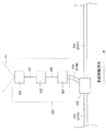
本発明の第1の実施の形態による移動体光通信システムについて図1乃至図6に基づき説明する。本実施の形態による移動体光通信システム1は、新幹線などの鉄道車両と、インターネットなどのネットワークとの間で高速通信を行うためのシステムである。図1は移動体光通信システム1の全体構成を示す説明図である。移動体光通信システム1は線路2、車両3、複数の基地局4、中継局5、インターネット公衆基地局6を備えている。線路2に沿って複数の漏洩光ファイバ10、複数の光ファイバ20、複数の受光装置21が設けられている。
A mobile optical communication system according to a first embodiment of the present invention will be described with reference to FIGS. A mobile
車両3は線路2に沿って移動する。車両3には、受信用光ファイバ31、複数の受光装置32、復調装置33、送信用光ファイバ34、信号生成装置35、複数の光送信装置36が設けられている。
The vehicle 3 moves along the
複数の基地局4は線路上に一定の間隔で設けられている。基地局4はそれぞれ中継局5にネットワーク回線によって接続されている。中継局5はインターネット公衆基地局6にネットワーク回線によって接続されている。複数の基地局4が設けられる間隔は、線路上に複数の車両が存在する場合、複数の車両の間で信号が混線しないように、各基地局4の間に車両3が最大でも1台のみ存在するような間隔であればよい。例えば、新幹線などの鉄道車両において、車両の現在位置はATC(自動列車制御装置)によって常時監視されており、その制御区間内には必ず一台の車両しか走行していない。このため、本実施の形態でも、ATCが設置された箇所に基地局4を設置するのが好適である。例えば、新幹線などで設置されているATCは主として3000m間隔で設置されており、ATCの集中制御方式では主として20km毎に複数のATCを集中制御している。よって本実施の形態においても、例えば、基地局4は3000m毎に設置され、複数の基地局4を束ねる中継局5は20km毎に設置されるのが好適である。
The plurality of
以下では、車両3の移動方向(図1)に関して上流側を単に上流側と表し、車両3の移動方向に関して下流側を単に下流側と表す。 Hereinafter, the upstream side with respect to the moving direction of the vehicle 3 (FIG. 1) is simply referred to as the upstream side, and the downstream side with respect to the moving direction of the vehicle 3 is simply referred to as the downstream side.
まず、ダウンリンク、即ち線路2側に設けられた漏洩光ファイバ10から車両3に光を送信するための構成について説明する。
First, a configuration for transmitting light from the leaky
各漏洩光ファイバ10は隣接する2つの基地局4の間に敷設されている。2つの基地局4のうち上流側もしくは下流側いずれか一方の基地局4に漏洩光ファイバ10が接続されている。本実施の形態では、漏洩光ファイバ10は上流側の基地局4に接続されているとする。基地局4は漏洩光ファイバ10に光信号を送信する。
Each leakage
図2は漏洩光ファイバ10の構造を示す斜視図である。図3は漏洩光ファイバ10を光軸方向(車両3の移動方向)に直交する方向に切断した面による断面図である。漏洩光ファイバの長手方向は車両3の移動方向と等しい。
FIG. 2 is a perspective view showing the structure of the leaky
図2、図3に示すように、漏洩光ファイバ10はコア11、クラッド12、光漏洩部13を備えている。コア11は漏洩光ファイバ10の中心部分に設けられている。クラッド12はコア11に外接している。光漏洩部13はコア11に接して、コア11の周方向の一部に設けられている。図2に示すように、光漏洩部13は長手方向に沿って断続的に複数、例えば光漏洩部13A,13B,13Cのように設けられている。漏洩光ファイバ10内の光の伝播方向と車両3の進行方向とは同じである。この場合、光漏洩部13Aが設けられた方を上流側、13Cが設けられた方を下流側とする。
As shown in FIGS. 2 and 3, the leaky
例えば車両3の移動方向における長さ(車両3の長さ)を400mとした場合、光漏洩部13は車両3の移動方向の長さ400m以下の間隔で設けられており、漏洩光ファイバ10は光漏洩部13が設けられた箇所が移動する車両3の底面と対向するように上を向くように敷設されている。図1に示すように、基地局4の近傍で、車両3の移動方向に関して上流側の線路2上には漏洩光ファイバ10が設けられていない区間41が存在する。このような区間41においても、基地局4の上流側であって基地局4に最も近い光漏洩部13と、基地局4の下流側であって基地局4に最も近い光漏洩部13との距離は車両3の移動方向の長さ以下である。即ち、線路2上には、光漏洩部13が車両3の長さより短い間隔で必ず存在する。
For example, when the length in the moving direction of the vehicle 3 (the length of the vehicle 3) is 400 m, the
光漏洩部13の漏洩率をLとする。漏洩率Lはコア11内を進行する光の量に対する、光漏洩部13から漏れ出る光の量の割合である。各光漏洩部13の漏洩量を一定にするために、下流側に行くほど漏洩率を漸次増加させる。すなわち、漏洩光ファイバ10の上流から数えてi番目の光漏洩部13の漏洩率Liが Li=Li−1/(1−Li−1) になるように、あるいは1番目の光漏洩部13Aの漏洩率をL1とした場合に、Liが Li=1/(1−(i−1)*L1) となるように、漏洩率を変化させる。例えば、光ファイバ10への光信号の投入量を10mWとし、各光漏洩部13における漏洩量を50μW一定とした場合、光漏洩部13Aの漏洩率は0.5%、光漏洩部13Bの漏洩率は0.5025%、光漏洩部13Cの漏洩率は0.5051%、となるように、漸次増加させて設置する。漏洩率Liは、例えば光漏洩部13の屈折率または大きさを変化させることにより調整する。Let the leakage rate of the
また、車両3の移動方向における光漏洩部13の長さは、伝送レートの1ビット分の波長の長さ以下とする。もし光漏洩部13の長さが伝送レートの1ビット分の光信号の空間的な長さ以上になると、複数個のビット信号が一度に空間に放射される。これらの複数のビット信号が空間的に混じりあってしまった場合には信号の歪みが生じてしまい、ビットエラーの可能性が非常に大きくなってしまう。漏洩光ファイバ10の伝送レートを1Gb/sとすると、1ビットに相当する光信号の空間的な長さはおよそ20〜30cm程度である。このため光漏洩部13の長手方向の長さも1ビットに相当する光信号の空間的な長さ以下とするのが好ましい。
In addition, the length of the
車両3の底面には、複数の受光装置32が漏洩光ファイバ10に対向して配置されている。複数の受光装置32は、一定の長さd(図4)以下の間隔で車両3の移動方向に沿って、車両3の移動方向全体にわたって配置されている。受光装置32は、例えば半導体受光素子と、信号波形整形装置及び半導体レーザとで構成される。受光装置32は、漏洩光ファイバ10の光漏洩部13から照射された光を、半導体受光素子で一旦電気信号に変換し、信号波形を整形した後、半導体レーザにより電気信号を光信号に再び変換して出力する。図4は漏洩光ファイバ10から照射された光の軌跡P1を車両3の移動方向及び上下方向に直交する方向から見た側面図である。図4に示すように、光漏洩部13から照射された光が受光装置32(32A,32B,32C,32D)で受光される。長さdは以下のようにして決定される。側面(車両3の移動方向および上下方向と直交する方向)から見ると光の軌跡P1は略三角形状である。この光が車両3に照射され光像が形成される。この光像の車両3の移動方向における長さがdである。
A plurality of
図1及び図5に示されるように、複数の受光装置32は光ファイバ31によって復調装置33に接続されている。図1では、複数の受光装置32が一本の光ファイバ31で接続されているように見えるが、実際には図5に示されるように各受光装置32(32A,32B,32C)は、複数の光ファイバ31(31A,31B,31C)によりそれぞれ独立して復調装置33に接続されている。各受光装置32で受光された信号は復調装置33に送られる。復調装置33は信号の波形を再生する。各光ファイバ31は同じ材質で作られている。また、図5に示すように、各光ファイバ31は屈曲して配線されることにより、同じ長さとなるように構成されている。このため、同時刻に各受光装置32で受信された光信号は同時に復調装置33に辿り着く。よって、各受光装置32から送られてくる光信号にズレがないため、復調装置33で信号の再生を容易に行うことができる。
As shown in FIGS. 1 and 5, the plurality of
次に、アップリンク、即ち車両3から線路2側の光ファイバ20に光を送信するための構成について説明する。
Next, a configuration for transmitting light from the uplink, that is, the
図1に示されるように、車両3には信号生成装置35が設けられている。車両3の底面には複数の光送信装置36が車両3の移動方向に沿って、車両3の長さ全体に渡って配置されている。また複数の光送信装置36は車両3の移動方向に沿って、所定の間隔で設けられている。各光送信装置36は信号生成装置35と光ファイバ34により接続されている。
As shown in FIG. 1, the signal generator 35 is provided in the vehicle 3. A plurality of
線路2上の受光装置21は、車両3の移動方向の長さより短い間隔で設けられている。本実施の形態では光漏洩部13と受光装置21とは同じ箇所に配置されている。すなわち、各受光装置21間の間隔と各光漏洩部13間の間隔は同じになっている。受光装置21は車両3の移動により、光送信装置36に対向可能な位置に設けられている。隣接する2つの基地局4の間に存在する全ての受光装置21は、隣接する基地局4のうち上流側の基地局4に光ファイバ20によって接続されている。受光装置21は、例えば半導体受光素子と、信号波形整形装置及び半導体レーザとで構成される。受光装置21は、光送信装置36から照射された光を、半導体受光素子で一旦電気信号に変換し、信号波形を整形した後、半導体レーザにより電気信号を光信号に再び変換して出力する。また、図5に示した光ファイバ31と同様に、実際には図6に示すように、各受光装置21(21A,21B)は複数の光ファイバ20(20A,20B)によりそれぞれ独立して基地局4に接続されている。各光ファイバ20は同じ材質で作られている。図5に示す光ファイバ31と同様に、各光ファイバ20は一部を屈曲して配線されることにより、同じ長さとなるように構成されている。このため、同時刻に各受光装置21で受信された光信号は同時に基地局4に辿り着く。よって、各受光装置21から送られてくる光信号にズレがないため、ビットエラーの少ない光通信が達成される。
The
図6は、光送信装置36から照射された光の軌跡P2を示す側面図である。側面(車両3の移動方向及び上下方向に直交する方向)から見ると光の軌跡P2は略三角形状をしている。この光が線路2上に照射され光像を形成する。図6に示すように、隣り合う光送信装置36は、それぞれの光送信装置36から線路上に設置された受光装置21(21A,21B)に照射された場合には、その光像が、車両3の移動方向において受光装置21上で重なるように配置されている。言い換えれば、車両3が線路2に沿って移動したときに任意の隣接する2つの光送信装置36から線路2に向けて照射されたそれぞれの光像は重なる領域を有し、その重なる領域は、各受光装置21を通過するように配置されている。また、車両3側の隣り合った2つの光送信装置36から放射される光(2ビーム)と、線路2側の光漏洩部13から放射される光(1ビーム)との、少なくとも3ビームの波長は、干渉ノイズを避けるために互いに異なっている。即ち、任意の隣接する2つの光送信装置36から照射される光の波長は、互いに異なり、且つ光漏洩部13から送出される光の波長とも異なっている。
FIG. 6 is a side view showing the locus P2 of the light emitted from the
上記説明した移動体光通信システム1の構成によれば、基地局4から送信された光は、コア11とクラッド12の間で反射を繰り返しながらコア11の内部を進行する。光漏洩部13に入射した光の一部は漏洩光ファイバ10の外部へと漏れ出る。外部に漏れ出た光は車両3の受光装置32で受光される。受光された光は光ファイバ31を介して復調装置33に伝送され、復調装置33で光信号が再生される。復調装置33で再生された光信号は車両3内の図示しない端末に送られる。一方、車両3の信号生成装置35によって生成された光信号は光送信装置36から線路2側へと照射される。照射された光信号は受光装置21で受光され光ファイバ20を介して基地局4へと送られる。基地局4から中継局5に送られた信号は、復調装置(図示せず)で復調されて、インターネットなどのネットワークに送出される。
According to the configuration of the mobile
本実施の形態ではATCと基地局4は同じ位置に設けられている。つまり、隣接する2つの基地局4の間には車両3は最大でも1台しか存在しない。このような場合には以下のような切れ目のない通信の受け渡し(ハンドオーバー)が可能になる。隣接する2つの基地局4のうち車両3の移動方向上流側の基地局4を上流側基地局4とし、他方の基地局4を下流側基地局4と表現する。車両3は、上流側基地局4と下流側基地局4との間を走行し、上流側基地局4と通信を行っている。車両3が下流側基地局4を通過中であることをATCが判断すると同時に、下流側基地局4は、下流側基地局4に接続された漏洩光ファイバ10に車両3向けの光信号を送る。同時に下流側基地局4は各受光装置21で受信される光信号を処理するように設定される。これにより下流側基地局4と車両3との通信の準備が完了する。ただしこの段階では、それまで通信を行っていた上流側基地局4でも、車両3との間の通信を続けている。この通信は、車両3が下流側基地局4を通過した後に終了してもよいし、次の車両3が進入してきて、その車両3に通信対象を切り替えるまで続けていても構わない。これらの制御は、中継局5において集中管理されて行われる。これにより、基地局4を通過する瞬間でも、切れ目の無い通信の受け渡しが可能になる。
In this embodiment, the ATC and the
また、通信の切り替えに、線路側に設置された受光装置21を利用することもできる。上流側基地局4に接続された受光装置21のうち最も下流側にある受光装置21に、車両3からの光信号が入力されたことを検知した瞬間に、下流側基地局4は、下流側基地局4に接続された漏洩光ファイバ10に、車両3向けの光信号を送る。同時に下流側基地局4は各受光装置21で受信される光信号を処理するように設定される。これらの制御は、中継局5において集中管理されて行われる。この方法によれば、基地局4の設置場所がATCの設置場所と異なっていても切れ目のない通信の受け渡し(ハンドオーバー)が可能である。
Further, the
上述した実施の形態による移動体光通信システム1によれば、光漏洩部13は車両3の移動方向の長さ以下の間隔をおいて、不連続に設けられている。このため、光漏洩部が連続的に設けられる場合と比べて、光漏洩部13から漏れ出る光の量を車両3の移動方向に関して限定することができる。これにより、光の無駄な漏洩を減らすことが出来、長距離に渡って光信号を伝播させることができる。また、車両3が線路2上のいずれの地点に位置していても、車両3は光漏洩部13から漏れ出た光を確実に受信することができる。よって、シームレスなダウンリンクが達成される。
According to the mobile
また、複数の受光装置32は、一定の長さd以下の間隔で車両3の移動方向に沿って、車両3の移動方向における長さの全体にわたって、車両3の底面に配置されている。このため、光漏洩部13から漏れ出た光を複数の受光装置32のうち少なくとも一つの受光装置32で確実に受信することができる。よって、シームレスなダウンリンクが達成される。
The plurality of
また、上述した実施の形態による移動体光通信システム1によれば、複数設けられた光漏洩部13の漏洩率は光の伝播方向下流側に向かって漸次増加している。このため各光漏洩部13から漏れ出る光の量を常に一定にすることができる。よって、安定した光通信を行うことができる。
Further, according to the mobile
また移動体光通信システム1は、漏洩光ファイバ10を用いているため装置の設置が容易であり、装置の設置に関わるコストを削減できる。また、光漏洩部13は周方向の一部に設けられている。このため光漏洩部13から漏れ出る光の量を周方向に関して限定することができる。これにより、光の無駄な漏洩を減らすことが出来、長距離に渡って光信号を伝播させることができる。
In addition, since the mobile
更に、複数の光送信装置36は、車両3が線路2に沿って移動したときに、任意の隣接する2つの光送信装置36から線路2に向けて照射されたそれぞれの光像は重なる領域を有し、この重なる領域は受光装置21を通過するように配置されている。よって、複数の光送信装置36のうち少なくとも一つの光送信装置36から放射された光は確実に受光装置21に受信される。よって、シームレスなアップリンクが達成される。また、任意の隣接する2つの光送信装置36から照射される光の波長は、互いに異なり、且つ光漏洩部13から送出される光の波長とも異なっている。このため、任意の隣接する2つの光送信装置36から照射される光および光漏洩部13から送出される光による干渉ノイズを避けることができる。このため、受光装置32は確実に光漏洩部13から送出される光を受光し、受光装置21は確実に光送信装置36から送出される光を受光する。従って、混線のない双方向通信が達成できる。
Furthermore, when the vehicle 3 moves along the
また、移動体光通信システム1の受光装置21は、車両3の移動方向に沿って、車両3の移動方向の長さより短い間隔で設けられている。よって、車両3が線路2のいずれの位置に位置していても、車両3から送信された光信号は受光装置21に受信される。よって、シームレスなアップリンクを達成できる。
The
また上述した実施の形態による移動体光通信システム1によれば、車両3の移動方向における光漏洩部13の長さは、伝送レートの1ビット分の光信号の空間的な長さ以下である。よって、複数個のビット信号が一度に空間に放射されることはない。よって、信号の歪みのない安定したダウンリンクを達成できる。
Moreover, according to the mobile
本発明の第2の実施の形態による移動体光通信システム101について図7に基づき説明する。第2の実施の形態による移動体光通信システム101は、車両が、停車中の別の車両を追い越す際のシームレスな光通信を実現する。移動体光通信システム101では線路が分岐し、再び結合している。即ち、線路102aは下流側の端部の分岐点B1において、線路102bと線路102cに分岐する。線路102bと線路102cとが一定の区間並列して設けられたのちそれぞれの下流側端部の合流点B2において線路102dに接続される。線路102aの上流側端部近傍に基地局104aが設けられている。また、線路102bの上流側端部近傍に基地局104bが設けられている。線路102cの上流側端部近傍に基地局104cが設けられている。また線路102dの上流側端部に基地局104dが設けられている。基地局104a〜104dが設けられる間隔は、基地局104a〜104dのそれぞれの間に車両が最大でも1台のみとなるような間隔である。本実施の形態においても基地局104a〜104dは、ATCの設置場所に設置されている。なお図7では、線路102bはαで途切れているが実際にはαで連続している。同様に線路102cもβで連続している。
A mobile
線路102a〜102dに沿ってそれぞれ、漏洩光ファイバ110a〜110d、複数の光ファイバ120a〜120dが設けられている。漏洩光ファイバ110a〜110d及び複数の光ファイバ120a〜120dはそれぞれ基地局104a〜104dに接続されている。基地局104a〜104dはそれぞれネットワーク回線によって中継局105に接続されており、送られてきた信号は復調装置(図示せず)で復調されて、さらに接続されているインターネット基地局106へ送出される。
Leaky
車両103x,103yにはそれぞれ、複数の受信用光ファイバ131x,131y、送信用光ファイバ134x,134y、復調装置133x,133y、信号生成装置135x,135y、及び光送信装置136x,136yが設けられている。車両103x,103yのこれらの装置の構成は、第1の実施の形態の車両3の複数の受信用光ファイバ31、送信用光ファイバ34、復調装置33、信号生成装置35、及び光送信装置36とそれぞれ同様である。
The
受光装置121a〜121dは、車両103xまたは車両103yの移動により光送信装置136xまたは光送信装置136yに対向可能な位置に設けられている。
The
漏洩光ファイバ110a〜110d、光ファイバ120a〜120d、及び受光装置121a〜121dの構成は第1の実施の形態の漏洩光ファイバ1、光ファイバ20、及び受光装置21とそれぞれ同様である。但し、基地局104b〜104d近傍の構成は以下のようになっている。
The configurations of the leaky
漏洩光ファイバ110a〜110dはそれぞれ光漏洩部113a〜113dを有する。複数の光漏洩部113aのうち最も下流側にある光漏洩部113aと、複数の光漏洩部113bのうち最も上流側にある光漏洩部113bとの距離は車両103xの長さ以下である。以下同様に、複数の光漏洩部113aのうち最も下流側にある光漏洩部113aと、複数の光漏洩部113cのうち最も上流側にある光漏洩部113cとの距離は車両103yの長さ以下である。複数の光漏洩部113bのうち最も下流側にある光漏洩部113bと、複数の光漏洩部113dのうち最も上流側にある光漏洩部113dとの距離は車両103xの長さ以下である。同様に、複数の光漏洩部113cのうち最も下流側にある光漏洩部113cと、光漏洩部113dのうち最も上流側にある光漏洩部113dとの距離は車両103yの長さ以下である。即ち線路102a,102b,102c,102d上のいずれの地点からでも、光漏洩部113a〜113dのいずれかが、車両103xおよび車両103yの長さの範囲内に存在する。
The leaky
各基地局104b〜104d近傍における受光装置121a〜121dの構成も、それぞれ光漏洩部113a〜113dの構成と同様である。即ち線路102a,102b,102c,102d上のいずれの地点からでも、受光装置121a〜121dのいずれかが、車両103xおよび車両103yの長さの範囲内に存在する。なお、本実施の形態では光漏洩部113と受光装置121は同じ箇所に設けられている。
The configurations of the
上述したように、基地局104a〜104dは、ATCの設置場所と同じ場所に設置されている。そのため、以下に示すように第2の実施の形態においても切れ目の無い通信の受け渡し(ハンドオーバー)が可能である。初めの状態では、線路102a〜102d上に車両103x、103yは共に存在しない。そこに、車両103xが線路102a上を進行して来る。この時点では車両103xは基地局104aと通信を行っている。車両103xは線路102bに進入する。車両103xが基地局104bを通過中であることをATCが判断すると同時に、基地局104bは、漏洩光ファイバ110bに、車両103x向けの光信号を送る。同時に基地局104bは受光装置121bで受信される光信号を処理するように設定される。これにより、基地局104bと車両103xとの通信の準備が完了する。ただしこの段階では、それまで通信を行っていた基地局104aでも、車両103xとの間の通信を続けている。この通信は、車両103xが基地局104bを通過した後に終了してもよいし、次の車両が進入してきて、その車両に通信対象を切り替えるまで続けていても構わない。続いて、車両103xは線路102b上の所定の位置に停車する。例えば、停車位置はホームが設置された区間などである。
As described above, the
次に車両103yが、基地局104aと通信を行いながら線路102a上を走行して来る。車両103yは線路102cに進入する。車両103yが基地局104cを通過中であることをATCが判断すると同時に、基地局104cは、漏洩光ファイバ110cに、車両103y向けの光信号を送る。同時に基地局104cは受光装置121cで受信される光信号を処理するように設定される。これにより、基地局104cと車両103yとの通信の準備が完了する。ただしこの段階では、それまで通信を行っていた基地局104aでも、車両103yとの間の通信を続けている。この通信は、車両103yが基地局104cを通過した後に終了してもよいし、次の車両が進入してきて、その車両に通信対象を切り替えるまで続けていても構わない。
Next, the
さらに車両103yは停車中の車両103xを追い越す。車両103yが基地局104dを通過中であることをATCが判断すると同時に、基地局104dは漏洩光ファイバ110dに、車両103y向けの光信号を送る。同時に基地局104dは受光装置121dで受信される光信号を処理するように設定される。これにより、基地局104dと車両103yとの通信の準備が完了する。ただしこの段階では、それまで通信を行っていた基地局104cでも、車両103yとの間の通信を続けている。この通信は、車両103yが基地局104dを通過した後に終了してもよいし、次の車両が進入してきて、その車両に通信対象を切り替えるまで続けていても構わない。
Further, the
車両103yが線路102dの下流側の基地局(図示せず)を通過した後に車両103xがホームを発車する。車両103xが基地局104dを通過中であるとATCが判断すると同時に、基地局104dは漏洩光ファイバ110dに、車両103x向けの光信号を送る。同時に基地局104dは受光装置121dで受信される光信号を処理するように設定される。これにより、基地局104dと車両103xとの通信の準備が完了する。ただしこの段階では、それまで通信を行っていた基地局104bでも、車両103xとの間の通信を続けている。この通信は、車両103xが基地局104dを通過した後に終了してもよいし、次の車両が線路102bに進入してきて、その車両に通信対象を切り替えるまで続けていても構わない。以上の制御は、中継局105において集中管理されて行われる。以上より、車両103xが基地局104b,104dを通過する瞬間でも、切れ目の無い通信の受け渡しが可能になる。また、車両103yが基地局104c,104dを通過する瞬間でも、切れ目の無い通信の受け渡し(ハンドオーバー)が可能になる。
After the
また、通信の切り替えに、それぞれの線路102a〜102dに設置されたそれぞれの受光装置121a〜121dを利用することもできる。車両103xが線路102aを走行しているとする。この段階で、車両103xが線路102bに進むことは予め決められているはずであり、中継局105はこの情報を元に基地局104bないし104cの制御を行うことが可能である。この場合には、基地局104aに接続された複数の受光装置121aのうち最も下流側にある受光装置121aに、車両103xからの光信号が入力されたことを検知した瞬間に、基地局104bは、基地局104bに接続された漏洩光ファイバ110bに、車両103x向けの光信号を送る。同時に基地局104bは各受光装置121bで受信される光信号を処理するように設定される。車両103xは線路102bに進入し停車する。
Moreover, each
次に、車両103yが線路102aを走行しているとする。この段階で、車両103yが線路102cに進むことは予め決められているはずであり、中継局105はこの情報を元に基地局104bないし104cの制御を行うことが可能である。この場合には、基地局104aに接続された複数の受光装置121aのうち最も下流側にある受光装置121aに、車両103yからの光信号が入力されたことを検知した瞬間に、基地局104cは、基地局104cに接続された漏洩光ファイバ110cに車両103y向けの光信号を送る。同時に基地局104cは各受光装置121cで受信される光信号を処理するように設定される。そして、基地局104cに接続された受光装置121cのうち最も下流側にある受光装置121cに、車両103yからの光信号が入力されたことを検知した瞬間に、基地局104dは、基地局104dに接続された漏洩光ファイバ110dに、車両103y向けの光信号を送る。同時に基地局104dは各受光装置121dで受信される光信号を処理するように設定される。
Next, it is assumed that the
車両103yが線路102dの下流側の基地局(図示せず)を通過した後、車両103xが発車する。基地局104bに接続された受光装置121bのうち最も下流側にある受光装置121bに、車両103xからの光信号が入力されたことを検知した瞬間に、基地局104dは、基地局104dに接続された漏洩光ファイバ110dに、車両103x向けの光信号を送る。同時に基地局104dは各受光装置121dで受信される光信号を処理するように設定される。以上の制御は、中継局105において集中管理されて行われる。この方法によれば、基地局の設置場所とATCの設置場所が異なる場合でも、切れ目のない通信の受け渡しが可能である。
After the
上述した第2の実施の形態による移動体光通信システム101によれば、車両103xを車両103yが追い越す際に、車両103x,103yは、基地局104a〜104dのいずれかと常に通信を行っている。このため、車両103x,103y共にシームレスな双方向通信が可能である。
According to the mobile
また、第2の実施の形態による移動体光通信システム101によれば線路102a〜dには、複数の車両(この例では車両103x、103y)が存在する。また、一本の線路102aが複数の線路102b、102cに分岐する分岐点B1と、線路102b、102cが再び1本の線路102dに合流する合流点B2が設けられている。そして、各線路(各区間)102a〜102dには、最大で1台の車両のみ(車両103xまたは車両103y)が存在するように設定されている。すなわち、分岐経路である線路102b、102cにおいてもそれぞれ車両は最大で1台のみ存在するように設定されている。さらに、線路102a〜102dに1対1で対応するように基地局104a〜104dが設けられている。そして、漏洩光ファイバ110a〜110dおよび受光装置121a〜121dが対応する線路102a〜102dに設けられている。よって、漏洩光ファイバ110a〜110dおよび受光装置121a〜121dは、対応する基地局104a〜104dに接続されている。このため、車両103x、103yの間で混線がない双方向通信を行うことができる。また、車両103x、103yが独立して、シームレスな双方向通信を行うことができる。
Moreover, according to the mobile
本発明による移動体光通信システム及び移動体光通信方法は上述した実施の形態に限定されず、特許請求の範囲に記載した範囲で種々の変形や改良が可能である。例えば、光ファイバ20及び受光装置21は線路2に沿って設けられていたが、受光装置21が線路2に沿って設けられていれば、光ファイバ20は線路2に沿って設けられていなくともよい。また、光送出手段に関しても同様に、光漏洩部13が線路2に沿って設けられていれば、漏洩光ファイバ10の非漏洩部は線路2に沿って設けられていなくともよい。
The mobile optical communication system and the mobile optical communication method according to the present invention are not limited to the above-described embodiments, and various modifications and improvements can be made within the scope described in the claims. For example, although the
また、図8のように、漏洩光ファイバ10の代わりに通常の(光漏洩部を有さない)光ファイバ210(210A、210B、210C)を用い、光漏洩部に相当する位置に光送信装置220を設けてもよい。光ファイバ210Aは車両移動方向上流側から延びており、下流側端部がファイバカプラ230に接続されている。光ファイバ210Cはその上流側端部がファイバカプラ230に接続され、下流側に延び、さらに下流側の図示せぬファイバカプラ230に接続されている。即ち、光ファイバ210A、210Cは線路に沿って延設されている。光ファイバ210Bは、光ファイバ210A及び210Cから枝分かれするような形で、一端がファイバカプラ230に接続されている。光ファイバ210Bの他端は光送信装置220(受光素子221)に接続している。光送信装置220は、フォトダイオードなどからなる受光素子221、信号処理回路222、レーザダイオードなどからなる発光素子223を備える。発光素子221と信号処理回路222とは、電気ケーブル226で接続され、信号処理回路222と、発光素子223とは電気ケーブル227で接続されている。光ファイバ210Aを伝播してきた光は、ファイバカプラ230に入力され、2つの光に分岐されて、光ファイバ210B、210Cに出力される。ファイバカプラ230から出力され、光ファイバ210Bを伝播してきた光は受光素子221に入力される。受光素子221は、光信号を電気信号に変換するO/E変換を行う。O/E変換によって生成された電気信号は、受光素子221から、電気ケーブル226を通って信号処理回路222に送信される。信号処理回路222は、入力された電気信号を増幅し、波形を整形する。増幅、及び、波形整形された電気信号は、光ケーブル227を通って発光素子223に送信される。発光素子223は電気信号を光信号に変換するE/O変換を行い、車両3(図4参照)に向けて光(軌跡P1)を送出する。
In addition, as shown in FIG. 8, instead of the leaky
あるいは、図9のように、漏洩光ファイバ10の代わりに通常の(光漏洩部を有さない)光ファイバ310(310A、310B)を用い、光漏洩部に相当する位置に光送信装置320を設けてもよい。光ファイバ310A、310Bは共に線路2に沿って延設されている。光送信装置320は、受光素子321、信号処理回路322、発光素子323、発光素子324を備える。受光素子321と信号処理回路322とは、電気ケーブル326で接続されている。信号処理回路322と、発光素子323とは電気ケーブル327で接続され、信号処理回路322と、発光素子324とは電気ケーブル328で接続されている。光ファイバ310Aは受光素子321と接続されている。また、発光素子324は光ファイバ310Bと接続されている。ファイバ310Aを伝播してきた光は、受光素子321に入力される。受光素子321は、光信号を電気信号に変換するO/E変換を行う。電気信号は、受光素子321から、電気ケーブル326を通って信号処理回路322に送信される。信号処理回路322は、電気信号を増幅し、波形を整形する。増幅、及び、波形整形された電気信号は、電気ケーブル326を通って発光素子323に送信されると共に、電気ケーブル328を通って発光素子324に送信される。発光素子323は電気信号を光信号に変換するE/O変換を行い、車両3に向けて光を送出する。また、発光素子324は電気信号を光信号に変換するE/O変換を行い、光ファイバ310Bに光を送出する。
光送信装置220、320を用いることによって、光はいったんO/E、E/O変換を経て波形が整形されるため、エラーの少ない精度のよい光通信が達成できる。尚、光送信装置220、320が線路2に沿って設けられていれば、光送信装置に接続する光ファイバは線路2に沿って設けられていなくともよい。Alternatively, as shown in FIG. 9, a normal optical fiber 310 (310 </ b> A, 310 </ b> B) is used instead of the leaking
By using the
また、図8、9の光送信装置220、320は、O/E、E/O変換の代わりに光−光制御などを行う構成でもよい。この場合にも、光はいったん光−光制御を経て波形が整形されるため、エラーの少ない精度のよい光通信が達成できる。なお、図8、9には図示されていないが、光ファイバ210Bと受光素子221、光ファイバ310Aと受光素子321、及び、発光素子324と光ファイバ310Bは、しかるべき光学部品を介して適切に接続されるものとする。
8 and 9 may be configured to perform light-light control or the like instead of O / E and E / O conversion. Also in this case, since the waveform of the light is once shaped through light-light control, it is possible to achieve high-precision optical communication with few errors. Although not shown in FIGS. 8 and 9, the
また、上述した実施の形態では車両側に光送信装置36、136x、136yを設けていた。しかし、車両側に光送信装置の代わりに送信用の漏洩光ファイバを設け、光漏洩部から光信号を送出するという構成であってもよい。
In the above-described embodiment, the
本発明の移動体通信システムは、新幹線などの鉄道車両と、インターネットとの間でブロードバンド通信を行うのに適している。 The mobile communication system of the present invention is suitable for performing broadband communication between a railway vehicle such as a Shinkansen and the Internet.
Claims (16)
該移動体の移動経路(2、102a−102d)に沿って敷設され、該複数の移動体側受光手段が受光可能な光を送出する複数のファイバ側光送出手段(13、113a−113d)を有する光ファイバケーブル(10、110a−110d)と、を備えた移動体光通信システム(1、101)であって、
該複数のファイバ側光送出手段は該移動体の移動方向における長さ以下の間隔で並設され、
該移動体側受光手段は、該移動体の移動方向に沿って、該ファイバ側光送出手段から該移動体に照射された光像の該移動体の移動方向における長さ(d)以下の所定間隔で並設されており、
該光ファイバケーブルは、コア(11)と、該コアよりも屈折率が低く該コアに外接したクラッド(12)と、該コアに接して形成され屈折率が該コアの屈折率より低く、かつ該クラッドの屈折率より高い光漏洩部(13、113a−113d)であって該移動体の移動方向に断続的に複数設けられた光漏洩部とを有する漏洩光ファイバケーブルであり、
該光漏洩部は該ファイバ側光送出手段として機能することを特徴とする移動体光通信システム。A moving body (3, 103x, 103y) having a plurality of moving body side light receiving means (32, 132x, 132y);
A plurality of fiber-side light transmitting means (13, 113a-113d) that are laid along the movement path (2, 102a-102d) of the moving body and that transmit light that can be received by the plurality of moving body-side light receiving means. A mobile optical communication system (1, 101) comprising optical fiber cables (10, 110a-110d),
The plurality of fiber-side light transmitting means are arranged in parallel at intervals equal to or less than the length in the moving direction of the moving body,
The moving body side light receiving means has a predetermined interval less than a length (d) in the moving direction of the moving body of the optical image irradiated to the moving body from the fiber side light sending means along the moving direction of the moving body. Are juxtaposed ,
The optical fiber cable includes a core (11), a clad (12) having a lower refractive index than the core and circumscribing the core, a refractive index formed in contact with the core and lower than a refractive index of the core, and A leakage optical fiber cable having a light leakage portion (13, 113a-113d) higher than the refractive index of the clad and a plurality of light leakage portions intermittently provided in the moving direction of the moving body;
The mobile optical communication system, wherein the light leakage part functions as the fiber side light transmitting means .
該移動体の移動経路(2、102a−102d)に沿って敷設され、該複数の移動体側受光手段が受光可能な光を送出する複数のファイバ側光送出手段(13、113a−113d)を有する光ファイバケーブル(10、110a−110d)と、を備えた移動体光通信システム(1、101)であって、
該複数のファイバ側光送出手段は該移動体の移動方向における長さ以下の間隔で並設され、
該移動体側受光手段は、該移動体の移動方向に沿って、該ファイバ側光送出手段から該移動体に照射された光像の該移動体の移動方向における長さ(d)以下の所定間隔で並設されており、
該移動体は、それぞれ該複数の移動体側受光手段(132x、132y)を有する複数の移動体(103x、103y)を備え、
該移動経路には、1本の経路が複数の分岐経路(102b、102c)に分岐する分岐位置(B1)と、該複数の分岐経路が再び1本の経路に合流する合流位置(B2)が設けられ、
該移動経路は、各区間に該複数の移動体のうち1台のみが存在するように設定される複数の区間(102a−102d)を有し、
各分岐経路は、該複数の区間のうちの一区間として機能し、
各区間に1対1で対応するように複数の基地局(104a−104d)が設けられ、
各区間における該複数のファイバ側光送出手段は対応する該基地局に接続されていることを特徴とする移動体光通信システム。 A moving body (3, 103x, 103y) having a plurality of moving body side light receiving means (32, 132x, 132y);
A plurality of fiber-side light transmitting means (13, 113a-113d) that are laid along the movement path (2, 102a-102d) of the moving body and that transmit light that can be received by the plurality of moving body-side light receiving means. A mobile optical communication system (1, 101) comprising optical fiber cables (10, 110a-110d),
The plurality of fiber-side light transmitting means are arranged in parallel at intervals equal to or less than the length in the moving direction of the moving body,
The moving body side light receiving means has a predetermined interval less than a length (d) in the moving direction of the moving body of the optical image irradiated to the moving body from the fiber side light sending means along the moving direction of the moving body. Are juxtaposed,
The moving body includes a plurality of moving bodies (103x, 103y) each having the plurality of moving body side light receiving means (132x, 132y),
The travel path includes a branch position (B1) where one path branches into a plurality of branch paths (102b, 102c), and a merge position (B2) where the plurality of branch paths merge into one path again. Provided,
The movement route has a plurality of sections (102a-102d) set so that only one of the plurality of moving bodies exists in each section,
Each branch route functions as one section of the plurality of sections,
A plurality of base stations (104a-104d) are provided so as to correspond to each section on a one-to-one basis,
The mobile optical communication system, wherein the plurality of fiber-side optical transmission means in each section are connected to the corresponding base station .
該移動体の移動経路(2、102a−102d)に沿って敷設され、該複数の移動体側光送出手段から送出された光を受光可能な複数のファイバ側受光手段(21、121a−121d)を有する光ファイバケーブル(10、110a−110d)と、を備えた移動体光通信システム(1、101)であって、A plurality of fiber side light receiving means (21, 121a-121d) which are laid along the moving path (2, 102a-102d) of the moving body and are capable of receiving light transmitted from the plurality of moving body side light transmitting means. A mobile optical communication system (1, 101) comprising: an optical fiber cable (10, 110a-110d) comprising:
該複数の移動体側光送出手段は移動体の移動方向に沿って配置され、The plurality of moving body side light sending means are arranged along the moving direction of the moving body,
該移動体が該移動経路に沿って移動したときに、任意の隣接する2つの移動体側光送出手段から該移動経路に向けて照射されたそれぞれの光像は重なる領域を有し、該重なる領域は、各ファイバ側受光手段を通過するように配置されており、When the moving body moves along the moving path, the respective light images irradiated toward the moving path from any two adjacent moving body-side light transmission means have overlapping areas, and the overlapping areas Are arranged to pass through each fiber side light receiving means,
該複数のファイバ側受光手段は該移動体の移動方向における長さ以下の間隔で並設されており、The plurality of fiber side light receiving means are arranged in parallel at intervals equal to or less than the length in the moving direction of the moving body,
任意の隣接する2つの移動体側光送出手段から送出される光の波長は互いに異なっていることを特徴とする移動体光通信システム。2. A mobile optical communication system, wherein wavelengths of light transmitted from any two adjacent mobile-side light transmitting means are different from each other.
該移動経路には、1本の経路が複数の分岐経路(102b、102c)に分岐する分岐位置(B1)と、該複数の分岐経路が再び1本の経路に合流する合流位置(B2)が設けられ、The travel path includes a branch position (B1) where one path branches into a plurality of branch paths (102b, 102c), and a merge position (B2) where the plurality of branch paths merge into one path again. Provided,
該移動経路は、各区間に該複数の移動体のうち1台のみが存在するように設定される複数の区間(102a−102d)を有し、The movement route has a plurality of sections (102a-102d) set so that only one of the plurality of moving bodies exists in each section,
各分岐経路は、該複数の区間のうちの一区間として機能し、Each branch route functions as one section of the plurality of sections,
各区間に1対1で対応するように複数の基地局(104a−104d)が設けられ、A plurality of base stations (104a-104d) are provided so as to correspond to each section on a one-to-one basis,
各区間における該複数のファイバ側受光手段は対応する該基地局に接続されていることを特徴とする請求項7記載の移動体光通信システム。8. The mobile optical communication system according to claim 7, wherein the plurality of fiber side light receiving means in each section are connected to the corresponding base station.
該移動体の移動経路(2、102a−102d)に沿って敷設され、該複数の移動体側受光手段が受光可能な光を送出する複数のファイバ側光送出手段(13、113a−113d)を有する第1の光ファイバケーブル(20、120a−120d)と、A plurality of fiber-side light transmitting means (13, 113a-113d) that are laid along the movement path (2, 102a-102d) of the moving body and that transmit light that can be received by the plurality of moving body-side light receiving means. A first optical fiber cable (20, 120a-120d);
該複数の移動体側光送出手段から送出された光を受光可能な複数のファイバ側受光手段(21、121a−121d)を有する第2の光ファイバケーブル(10、110a−110d)と、を備えた移動体光通信システム(1、101)であって、A second optical fiber cable (10, 110a-110d) having a plurality of fiber side light receiving means (21, 121a-121d) capable of receiving the light transmitted from the plurality of mobile body side light transmitting means. A mobile optical communication system (1, 101),
該複数のファイバ側光送出手段は該移動体の移動方向における長さ以下の間隔で並設され、The plurality of fiber-side light transmitting means are arranged in parallel at intervals equal to or less than the length in the moving direction of the moving body,
該移動体側受光手段は、該移動体の移動方向に沿って、該ファイバ側光送出手段から該移動体に照射された光像の該移動体の移動方向における長さ(d)以下の所定間隔で並設されており、The moving body side light receiving means has a predetermined interval less than a length (d) in the moving direction of the moving body of the optical image irradiated to the moving body from the fiber side light sending means along the moving direction of the moving body. Are juxtaposed,
該移動体が該移動経路に沿って移動したときに、任意の隣接する2つの移動体側光送出手段から該移動経路に向けて照射されたそれぞれの光像は重なる領域を有し、該重なる領域は、各ファイバ側受光手段を通過するように配置されており、When the moving body moves along the moving path, the respective light images irradiated toward the moving path from any two adjacent moving body-side light transmission means have overlapping areas, and the overlapping areas Are arranged to pass through each fiber side light receiving means,
該複数のファイバ側受光手段は該移動体の移動方向における長さ以下の間隔で並設されており、The plurality of fiber side light receiving means are arranged in parallel at intervals equal to or less than the length in the moving direction of the moving body,
任意の隣接する2つの移動体側光送出手段から送出される光の波長は、互いに異なり、且つファイバ側光送出手段から送出される光の波長とも異なっていることを特徴とする移動体光通信システム。2. A mobile optical communication system characterized in that the wavelengths of light transmitted from any two adjacent mobile-side light transmitting means are different from each other and the wavelengths of light transmitted from the fiber-side light transmitting means are also different. .
該光漏洩部は該ファイバ側光送出手段として機能することを特徴とする請求項9に記載の移動体光通信システム。10. The mobile optical communication system according to claim 9, wherein the light leakage part functions as the fiber-side light transmission means.
該移動経路には、1本の経路が複数の分岐経路(102b、102c)に分岐する分岐位置(B1)と、該複数の分岐経路が再び1本の経路に合流する合流位置(B2)が設けられ、
該移動経路は、各区間に該複数の移動体のうち1台のみが存在するように設定される複数の区間(102a−102d)を有し、
各分岐経路は、該複数の区間のうちの一区間として機能し、
各区間に1対1で対応するように複数の基地局(104a−104d)が設けられ、
各区間における該複数のファイバ側光送出手段及び複数のファイバ側受光手段は対応する該基地局に接続されていることを特徴とする請求項9記載の移動体光通信システム。 The moving body includes a plurality of moving bodies (103x, 103y) each having the plurality of moving body side light transmitting means (136x, 136y) and the plurality of moving body side light receiving means (132x, 132y),
The travel path includes a branch position (B1) where one path branches into a plurality of branch paths (102b, 102c), and a merge position (B2) where the plurality of branch paths merge into one path again. Provided,
The movement route has a plurality of sections (102a-102d) set so that only one of the plurality of moving bodies exists in each section,
Each branch route functions as one section of the plurality of sections,
A plurality of base stations (104a-104d) are provided so as to correspond to each section on a one-to-one basis,
10. The mobile optical communication system according to claim 9, wherein the plurality of fiber side light transmitting means and the plurality of fiber side light receiving means in each section are connected to the corresponding base station.
該送出された光を、該移動体の経路上に設けられた複数の受光位置のうち少なくとも一つの受光位置で受光し、
該移動体の経路上の該複数の受光位置のうち少なくとも一つの受光位置で受光された光を、該移動体の経路に沿って伝達する移動体光通信方法において、
該移動体が該移動体の経路に沿って移動したときに、任意の隣接する2つの移動体側送出位置から該移動体の経路に向けて照射されたそれぞれの光像は重なる領域を有し、該重なる領域は、該移動体の経路上の各受光位置を通過するように配置されており、
該経路上の該複数の受光位置は該移動体の移動方向における長さ以下の間隔で並設されており、
任意の隣接する2つの移動体側送出位置から送出される光の波長は互いに異なっていることを特徴とする移動体光通信方法。 Sending light from a plurality of sending positions provided in the moving body along the moving direction of the moving body,
The transmitted light is received at at least one light receiving position among a plurality of light receiving positions provided on the path of the moving body,
In the mobile optical communication method for transmitting light received at at least one light receiving position among the plurality of light receiving positions on the path of the mobile body along the path of the mobile body,
When the moving body moves along the path of the moving body, the respective light images emitted toward the path of the moving body from any two adjacent mobile-side transmission positions have overlapping areas, The overlapping area is arranged to pass through each light receiving position on the path of the moving body,
The plurality of light receiving positions on the path are arranged in parallel at intervals equal to or less than the length in the moving direction of the moving body,
A mobile optical communication method, wherein wavelengths of light transmitted from any two adjacent mobile-side transmission positions are different from each other.
該移動体の経路上に設けられた複数の送出位置から、該移動体の経路に沿って伝達された光を該移動体に向けて送出し、From a plurality of transmission positions provided on the path of the mobile body, the light transmitted along the path of the mobile body is transmitted toward the mobile body,
該移動体に向けて送出された光を、該移動体の複数の受光位置のうち少なくとも一つの受光位置で受光し、The light transmitted toward the moving body is received at at least one light receiving position among the plurality of light receiving positions of the moving body,
該移動体の移動方向に沿って該移動体に設けられた複数の送出位置から光を送出し、Transmitting light from a plurality of transmission positions provided in the moving body along the moving direction of the moving body;
該送出された光を、該移動体の経路上に設けられた複数の受光位置のうち少なくとも一つの受光位置で受光し、The transmitted light is received at at least one light receiving position among a plurality of light receiving positions provided on the path of the moving body,
該移動体の経路上の該複数の受光位置のうち少なくとも一つの受光位置で受光された光を、該移動体の経路に沿って伝達する移動体光通信方法において、In the mobile optical communication method for transmitting light received at at least one light receiving position among the plurality of light receiving positions on the path of the mobile body along the path of the mobile body,
該経路上の該複数の送出位置は、該移動体の移動方向における長さ以下の間隔で設けられ、The plurality of delivery positions on the route are provided at intervals equal to or shorter than the length in the moving direction of the moving body,
該移動体の該複数の受光位置は、該移動体の移動方向に沿って、該経路上の該複数の送出位置から該移動体に照射された光像の該移動体の移動方向における長さ(d)以下の所定間隔で並設され、The plurality of light receiving positions of the moving body are the lengths in the moving direction of the moving body of light images irradiated on the moving body from the plurality of sending positions on the path along the moving direction of the moving body. (D) are arranged in parallel at the following predetermined intervals,
該移動体が該移動体の経路に沿って移動したときに、任意の隣接する2つの移動体側送出位置から該移動体の経路に向けて照射されたそれぞれの光像は重なる領域を有し、該重なる領域は、該移動体の経路上の各受光位置を通過するように配置されており、When the moving body moves along the path of the moving body, the respective light images emitted toward the path of the moving body from any two adjacent mobile-side transmission positions have overlapping areas, The overlapping area is arranged to pass through each light receiving position on the path of the moving body,
該経路上の該複数の受光位置は該移動体の移動方向における長さ以下の間隔で並設されており、The plurality of light receiving positions on the path are arranged in parallel at intervals equal to or less than the length in the moving direction of the moving body,
任意の隣接する2つの移動体側送出位置から送出される光の波長は、互いに異なり、且つ経路上の送出位置から送出される光の波長とも異なっていることを特徴とする移動体光通信方法。A mobile optical communication method, wherein wavelengths of light transmitted from any two adjacent mobile-side transmission positions are different from each other, and are different from wavelengths of light transmitted from transmission positions on a path.
Priority Applications (1)
| Application Number | Priority Date | Filing Date | Title |
|---|---|---|---|
| JP2008528769A JP4863406B2 (en) | 2006-08-07 | 2007-07-20 | Mobile optical communication system and mobile optical communication method |
Applications Claiming Priority (4)
| Application Number | Priority Date | Filing Date | Title |
|---|---|---|---|
| JP2006214192 | 2006-08-07 | ||
| JP2006214192 | 2006-08-07 | ||
| JP2008528769A JP4863406B2 (en) | 2006-08-07 | 2007-07-20 | Mobile optical communication system and mobile optical communication method |
| PCT/JP2007/064331 WO2008018281A1 (en) | 2006-08-07 | 2007-07-20 | Mobile optical communication system and mobile optical communication method |
Publications (2)
| Publication Number | Publication Date |
|---|---|
| JPWO2008018281A1 JPWO2008018281A1 (en) | 2009-12-24 |
| JP4863406B2 true JP4863406B2 (en) | 2012-01-25 |
Family
ID=39032815
Family Applications (1)
| Application Number | Title | Priority Date | Filing Date |
|---|---|---|---|
| JP2008528769A Expired - Fee Related JP4863406B2 (en) | 2006-08-07 | 2007-07-20 | Mobile optical communication system and mobile optical communication method |
Country Status (4)
| Country | Link |
|---|---|
| EP (1) | EP2056492A4 (en) |
| JP (1) | JP4863406B2 (en) |
| CN (1) | CN101502028B (en) |
| WO (1) | WO2008018281A1 (en) |
Families Citing this family (15)
| Publication number | Priority date | Publication date | Assignee | Title |
|---|---|---|---|---|
| GB201020201D0 (en) | 2010-11-30 | 2011-01-12 | Airbus Uk Ltd | Data transmission network |
| DE102012217620A1 (en) * | 2012-09-27 | 2014-03-27 | Siemens Aktiengesellschaft | Method for operating a mobile device in a railway system, railway system and mobile device |
| FR3006835B1 (en) * | 2013-06-05 | 2015-06-19 | Reseau Ferre De France | BIDIRECTIONAL COMMUNICATION SYSTEMS CONTINUED BY ATMOSPHERIC LINKAGE |
| KR102394712B1 (en) * | 2015-09-09 | 2022-05-04 | 삼성전자주식회사 | Transporting system, transporting unit included therein |
| DE102016116396A1 (en) | 2016-09-01 | 2018-03-15 | Conductix-Wampfler Gmbh | Conductor line, pantograph, conductor rail system and method for contactless data transmission |
| KR101936271B1 (en) * | 2016-10-10 | 2019-01-08 | 오학서 | Apparatus for Controlling Line Guide of Automated Material Handling System and the Method Thereof |
| DE102016224613A1 (en) * | 2016-12-09 | 2018-06-14 | Siemens Aktiengesellschaft | Network connection of vehicles |
| US9866325B1 (en) | 2017-03-28 | 2018-01-09 | Les Industries Show Canada Inc | System and method for bidirectional exchange of data with a mobile apparatus through at least one leaky optical fiber |
| EP3422604B1 (en) * | 2017-06-30 | 2020-03-04 | Vestel Elektronik Sanayi ve Ticaret A.S. | A system of visible light communication for a mass transit vehicle |
| US11333837B2 (en) | 2017-09-07 | 2022-05-17 | Murata Machinery, Ltd. | Optical communication system for rail-guided truck |
| JP2019114978A (en) * | 2017-12-25 | 2019-07-11 | 株式会社アウトスタンディングテクノロジー | Visible light transmission device |
| JP7347546B2 (en) * | 2020-01-27 | 2023-09-20 | 株式会社島津製作所 | Underwater optical communication equipment and underwater inspection system |
| CN111762236B (en) * | 2020-06-29 | 2022-05-10 | 交控科技股份有限公司 | Rail transit train positioning method, device and system |
| CN111891185B (en) * | 2020-07-24 | 2022-05-10 | 交控科技股份有限公司 | Rail transit train parking method and system |
| CN113904725A (en) * | 2021-09-30 | 2022-01-07 | 西安邮电大学 | Underwater optical communication system and method thereof |
Citations (6)
| Publication number | Priority date | Publication date | Assignee | Title |
|---|---|---|---|---|
| JPS63199303A (en) * | 1987-02-16 | 1988-08-17 | Fujikura Ltd | Leaky optical fiber and its production |
| JPH0263331A (en) * | 1988-08-30 | 1990-03-02 | Mitsubishi Electric Corp | Space information transmission system |
| JPH0815527A (en) * | 1994-07-04 | 1996-01-19 | Hitachi Cable Ltd | Side face light emitting plastic optical fiber and its production |
| JP2001168803A (en) * | 1999-12-08 | 2001-06-22 | Yagi Antenna Co Ltd | Light sending apparatus and light transmitter-receiver for optical communication |
| JP2001308798A (en) * | 2000-04-21 | 2001-11-02 | Hokuyo Automatic Co | Side face leakage optical fiber type light data transmission equipment |
| JP2004282685A (en) * | 2003-06-06 | 2004-10-07 | Global Com:Kk | Mobile optical communication system and mobile optical communication method |
Family Cites Families (14)
| Publication number | Priority date | Publication date | Assignee | Title |
|---|---|---|---|---|
| JPS63153489A (en) * | 1986-12-18 | 1988-06-25 | Mitsubishi Heavy Ind Ltd | Information detector for mobile body |
| FR2612146B1 (en) * | 1987-03-11 | 1991-11-29 | Comp Generale Electricite | INFORMATION TRANSMISSION SYSTEM FOR VEHICLES |
| JPH04125423A (en) * | 1990-09-17 | 1992-04-24 | Beam Soken:Kk | Lateral leakage optical fiber type level gage |
| JP2983600B2 (en) * | 1990-09-20 | 1999-11-29 | 小糸工業株式会社 | Optical space transmission equipment |
| JPH05329753A (en) * | 1992-05-26 | 1993-12-14 | Hitachi Ltd | Automatic production line equipment control system |
| DE69311345T2 (en) * | 1992-07-28 | 1997-11-06 | British Telecomm | DEVICE FOR WIRED SIGNAL TRANSMISSION BY LIGHT |
| JPH0811719A (en) * | 1994-06-29 | 1996-01-16 | Nec Corp | Mobile communication system |
| JP2001133652A (en) * | 1999-11-09 | 2001-05-18 | Hitachi Cable Ltd | Leakage optical fiber |
| JP2002063331A (en) * | 2000-08-21 | 2002-02-28 | Hiroyuki Kanazawa | Remote control type mobile public information system |
| JP2002156564A (en) * | 2000-09-05 | 2002-05-31 | Matsushita Electric Ind Co Ltd | Optical signal reader |
| JP2005064993A (en) * | 2003-08-18 | 2005-03-10 | Fuji Xerox Co Ltd | Apparatus and system of optical radio |
| JP2005284250A (en) * | 2004-03-04 | 2005-10-13 | Nakagawa Kenkyusho:Kk | Communication system and leakage optical fiber |
| EP1582430A1 (en) * | 2004-03-29 | 2005-10-05 | The Hong Kong Polytechnic University | System and process for monitoring railway tracks |
| JP2005329753A (en) * | 2004-05-18 | 2005-12-02 | Kojima Press Co Ltd | Cup holder |
-
2007
- 2007-07-20 EP EP07791069.3A patent/EP2056492A4/en not_active Withdrawn
- 2007-07-20 JP JP2008528769A patent/JP4863406B2/en not_active Expired - Fee Related
- 2007-07-20 WO PCT/JP2007/064331 patent/WO2008018281A1/en active Application Filing
- 2007-07-20 CN CN2007800293903A patent/CN101502028B/en not_active Expired - Fee Related
Patent Citations (6)
| Publication number | Priority date | Publication date | Assignee | Title |
|---|---|---|---|---|
| JPS63199303A (en) * | 1987-02-16 | 1988-08-17 | Fujikura Ltd | Leaky optical fiber and its production |
| JPH0263331A (en) * | 1988-08-30 | 1990-03-02 | Mitsubishi Electric Corp | Space information transmission system |
| JPH0815527A (en) * | 1994-07-04 | 1996-01-19 | Hitachi Cable Ltd | Side face light emitting plastic optical fiber and its production |
| JP2001168803A (en) * | 1999-12-08 | 2001-06-22 | Yagi Antenna Co Ltd | Light sending apparatus and light transmitter-receiver for optical communication |
| JP2001308798A (en) * | 2000-04-21 | 2001-11-02 | Hokuyo Automatic Co | Side face leakage optical fiber type light data transmission equipment |
| JP2004282685A (en) * | 2003-06-06 | 2004-10-07 | Global Com:Kk | Mobile optical communication system and mobile optical communication method |
Also Published As
| Publication number | Publication date |
|---|---|
| CN101502028A (en) | 2009-08-05 |
| EP2056492A4 (en) | 2016-07-06 |
| CN101502028B (en) | 2012-07-04 |
| WO2008018281A1 (en) | 2008-02-14 |
| EP2056492A1 (en) | 2009-05-06 |
| JPWO2008018281A1 (en) | 2009-12-24 |
Similar Documents
| Publication | Publication Date | Title |
|---|---|---|
| JP4863406B2 (en) | Mobile optical communication system and mobile optical communication method | |
| JP3521111B2 (en) | Single fiber bidirectional data link | |
| US5991478A (en) | Fiber optic rotary joint | |
| EP1019763A1 (en) | Fiber optic rotary joint | |
| CN103430068A (en) | Optical coupling unit for a unit for sending optical signals, unit for sending optical signals and an optical transceiver | |
| WO2015163124A1 (en) | Multicore/multimode fiber joining device | |
| TW202019113A (en) | Optical wireless unit, free space optical wireless control unit and free space optical wireless control method | |
| CN109641529A (en) | Trolley, current-collector, sliding contact line system and the method for the transmission of contactless data | |
| US20020164115A1 (en) | Optical fiber communication system, communications apparatus and optical transceiver | |
| US20160344478A1 (en) | Multimode fiber for modulatable source | |
| JP2005284250A (en) | Communication system and leakage optical fiber | |
| EP3382906A1 (en) | System and method for bidirectional exchange of data with a mobile apparatus through at least one leaky optical fiber | |
| JP7430993B2 (en) | Optical fiber parts, splitters and optical transmission systems | |
| JP5345459B2 (en) | Local signal light input / output method and local signal light input / output device | |
| US4678269A (en) | Concentric light source to fiber coupling system | |
| JP5483738B2 (en) | Light incident / exit device and light incident / exit method | |
| US7054511B2 (en) | Optical coupling device for single mode optical fibers | |
| JP2007259179A (en) | Optical communication apparatus | |
| TW201925052A (en) | Apparatus for controlling line guide of automatic material handling system and the method thereof having the set length of the optical lines be set longer than that in the prior art | |
| JP2004515820A (en) | Optical waveguide cable and method for transmitting optical signals, for example by wavelength division multiplexing technology | |
| JPS6117641Y2 (en) | ||
| JPS6177019A (en) | Method and device for switching optical fiber cable without momentary disconnection | |
| CN112713937A (en) | Indoor visible light communication system | |
| Aggarwal et al. | Digital communications for protection. III. Fibre optics | |
| JP3106932B2 (en) | Optical splitter |
Legal Events
| Date | Code | Title | Description |
|---|---|---|---|
| A621 | Written request for application examination |
Free format text: JAPANESE INTERMEDIATE CODE: A621 Effective date: 20100203 |
|
| A131 | Notification of reasons for refusal |
Free format text: JAPANESE INTERMEDIATE CODE: A131 Effective date: 20110809 |
|
| A521 | Request for written amendment filed |
Free format text: JAPANESE INTERMEDIATE CODE: A523 Effective date: 20110922 |
|
| TRDD | Decision of grant or rejection written | ||
| A01 | Written decision to grant a patent or to grant a registration (utility model) |
Free format text: JAPANESE INTERMEDIATE CODE: A01 Effective date: 20111104 |
|
| A01 | Written decision to grant a patent or to grant a registration (utility model) |
Free format text: JAPANESE INTERMEDIATE CODE: A01 |
|
| A61 | First payment of annual fees (during grant procedure) |
Free format text: JAPANESE INTERMEDIATE CODE: A61 Effective date: 20111104 |
|
| FPAY | Renewal fee payment (event date is renewal date of database) |
Free format text: PAYMENT UNTIL: 20141118 Year of fee payment: 3 |
|
| R150 | Certificate of patent or registration of utility model |
Free format text: JAPANESE INTERMEDIATE CODE: R150 |
|
| LAPS | Cancellation because of no payment of annual fees |