JP4860964B2 - Apparatus for centering rotor assembly bearings - Google Patents
Apparatus for centering rotor assembly bearings Download PDFInfo
- Publication number
- JP4860964B2 JP4860964B2 JP2005245801A JP2005245801A JP4860964B2 JP 4860964 B2 JP4860964 B2 JP 4860964B2 JP 2005245801 A JP2005245801 A JP 2005245801A JP 2005245801 A JP2005245801 A JP 2005245801A JP 4860964 B2 JP4860964 B2 JP 4860964B2
- Authority
- JP
- Japan
- Prior art keywords
- spring
- springs
- bearing assembly
- outer race
- assembly
- Prior art date
- Legal status (The legal status is an assumption and is not a legal conclusion. Google has not performed a legal analysis and makes no representation as to the accuracy of the status listed.)
- Expired - Fee Related
Links
Images


Classifications
-
- F—MECHANICAL ENGINEERING; LIGHTING; HEATING; WEAPONS; BLASTING
- F01—MACHINES OR ENGINES IN GENERAL; ENGINE PLANTS IN GENERAL; STEAM ENGINES
- F01D—NON-POSITIVE DISPLACEMENT MACHINES OR ENGINES, e.g. STEAM TURBINES
- F01D25/00—Component parts, details, or accessories, not provided for in, or of interest apart from, other groups
- F01D25/16—Arrangement of bearings; Supporting or mounting bearings in casings
- F01D25/162—Bearing supports
- F01D25/164—Flexible supports; Vibration damping means associated with the bearing
-
- F—MECHANICAL ENGINEERING; LIGHTING; HEATING; WEAPONS; BLASTING
- F16—ENGINEERING ELEMENTS AND UNITS; GENERAL MEASURES FOR PRODUCING AND MAINTAINING EFFECTIVE FUNCTIONING OF MACHINES OR INSTALLATIONS; THERMAL INSULATION IN GENERAL
- F16C—SHAFTS; FLEXIBLE SHAFTS; ELEMENTS OR CRANKSHAFT MECHANISMS; ROTARY BODIES OTHER THAN GEARING ELEMENTS; BEARINGS
- F16C27/00—Elastic or yielding bearings or bearing supports, for exclusively rotary movement
- F16C27/04—Ball or roller bearings, e.g. with resilient rolling bodies
- F16C27/045—Ball or roller bearings, e.g. with resilient rolling bodies with a fluid film, e.g. squeeze film damping
-
- F—MECHANICAL ENGINEERING; LIGHTING; HEATING; WEAPONS; BLASTING
- F05—INDEXING SCHEMES RELATING TO ENGINES OR PUMPS IN VARIOUS SUBCLASSES OF CLASSES F01-F04
- F05D—INDEXING SCHEME FOR ASPECTS RELATING TO NON-POSITIVE-DISPLACEMENT MACHINES OR ENGINES, GAS-TURBINES OR JET-PROPULSION PLANTS
- F05D2230/00—Manufacture
- F05D2230/60—Assembly methods
- F05D2230/64—Assembly methods using positioning or alignment devices for aligning or centring, e.g. pins
-
- F—MECHANICAL ENGINEERING; LIGHTING; HEATING; WEAPONS; BLASTING
- F16—ENGINEERING ELEMENTS AND UNITS; GENERAL MEASURES FOR PRODUCING AND MAINTAINING EFFECTIVE FUNCTIONING OF MACHINES OR INSTALLATIONS; THERMAL INSULATION IN GENERAL
- F16C—SHAFTS; FLEXIBLE SHAFTS; ELEMENTS OR CRANKSHAFT MECHANISMS; ROTARY BODIES OTHER THAN GEARING ELEMENTS; BEARINGS
- F16C19/00—Bearings with rolling contact, for exclusively rotary movement
- F16C19/22—Bearings with rolling contact, for exclusively rotary movement with bearing rollers essentially of the same size in one or more circular rows, e.g. needle bearings
- F16C19/24—Bearings with rolling contact, for exclusively rotary movement with bearing rollers essentially of the same size in one or more circular rows, e.g. needle bearings for radial load mainly
- F16C19/26—Bearings with rolling contact, for exclusively rotary movement with bearing rollers essentially of the same size in one or more circular rows, e.g. needle bearings for radial load mainly with a single row of rollers
-
- F—MECHANICAL ENGINEERING; LIGHTING; HEATING; WEAPONS; BLASTING
- F16—ENGINEERING ELEMENTS AND UNITS; GENERAL MEASURES FOR PRODUCING AND MAINTAINING EFFECTIVE FUNCTIONING OF MACHINES OR INSTALLATIONS; THERMAL INSULATION IN GENERAL
- F16C—SHAFTS; FLEXIBLE SHAFTS; ELEMENTS OR CRANKSHAFT MECHANISMS; ROTARY BODIES OTHER THAN GEARING ELEMENTS; BEARINGS
- F16C2360/00—Engines or pumps
- F16C2360/23—Gas turbine engines
Landscapes
- Engineering & Computer Science (AREA)
- General Engineering & Computer Science (AREA)
- Mechanical Engineering (AREA)
- Rolling Contact Bearings (AREA)
- Support Of The Bearing (AREA)
Description
本発明は、総括的にはガスタービンエンジンロータ組立体に関し、より具体的には、ガスタービンエンジンロータ組立体用の軸受組立体に関する。 The present invention relates generally to gas turbine engine rotor assemblies, and more specifically to bearing assemblies for gas turbine engine rotor assemblies.
ガスタービンエンジンは一般的に、ファンロータ組立体、圧縮機及びタービンを含む。ファンロータ組立体は、ロータシャフトから半径方向外向きに延びるファンブレードの列を備えたファンを含む。ロータシャフトは、タービンから圧縮機及びファンに動力及び回転運動を伝達し、複数の軸受組立体で長手方向に支持される。軸受組立体は、ロータシャフトを支持し、一般的にインナレース及びアウタレース内に置かれた転動体を含む。 Gas turbine engines typically include a fan rotor assembly, a compressor, and a turbine. The fan rotor assembly includes a fan with a row of fan blades extending radially outward from the rotor shaft. The rotor shaft transmits power and rotational motion from the turbine to the compressor and fan and is supported longitudinally by a plurality of bearing assemblies. The bearing assembly includes rolling elements that support the rotor shaft and are typically placed within the inner race and the outer race.
さらに、少なくとも幾つかの公知の軸受組立体は、軸受アウタレースに取付けられた複数の同一のばねを含む。このばねは、ロータシャフトの円周方向の周りに単一の列として等しい間隔を置いて配置されて、軸受に対して離散的な半径方向の剛性を与えかつ支持フレームに対してアウタレースをセンタリングする。ばねの第1の端部は、軸受組立体アウタレースに取付けられ、またばねの第2の端部は、支持フレームに結合したフランジに取付けられる。 In addition, at least some known bearing assemblies include a plurality of identical springs attached to the bearing outer race. The springs are equally spaced as a single row around the circumference of the rotor shaft to provide discrete radial stiffness to the bearing and center the outer race relative to the support frame. . The first end of the spring is attached to the bearing assembly outer race, and the second end of the spring is attached to a flange coupled to the support frame.
運転中、エンジン内に不釣合いがあると、エンジンロータシャフトを半径方向に変位させることになる。シャフトの半径方向の変位は、軸受組立体に伝達される。ばねは、単一の円周方向列として配置されているので、各ばねの撓みは同じである。並行なすなわち2重の列構成は、より短い軸方向間隔を使用することによって、軸受組立体の重量を最適化することを可能にする。しかしながら、この構成はまた、ばねの曲げ応力を低下させ、従って疲労寿命を高める。この応力場において、一般的な単一列構成は、より多くのばね、より大きな材料強度、より大きな断面慣性及び/又は大きなばね長さを必要とする。その結果、軸受組立体の価格及び重量は増加することになる。 During operation, any imbalance in the engine will cause the engine rotor shaft to be displaced radially. The radial displacement of the shaft is transmitted to the bearing assembly. Since the springs are arranged as a single circumferential row, the deflection of each spring is the same. The parallel or double row configuration allows the weight of the bearing assembly to be optimized by using shorter axial spacing. However, this configuration also reduces the bending stress of the spring and thus increases the fatigue life. In this stress field, a typical single row configuration requires more springs, greater material strength, greater cross-sectional inertia and / or greater spring length. As a result, the price and weight of the bearing assembly is increased.
損傷を与える可能性がある半径方向の力の影響を最小にするために、多くの場合、ばね数、断面積及びばね長さが増大される。その結果、軸受組立体の価格及び重量もまた増加する。
1つの態様では、ガスタービンエンジンロータ用の軸受組立体を提供する。本軸受組立体は、インナレースと、アウタレース組立体と、転動体とを含む。アウタレース組立体は、本体と、本体に取付けられた複数の第1のばねと、複数の第2のばねとを含む。各第1のばねは、対応する第2のばねと半径方向に整列してばね対を形成する。アウタレース組立体はまた、複数の結合部材を含む。各結合部材は、ばね対の第1のばねの第1の端部と第2のばねの第1の端部との間で延びかつそれらを結合する。アウタレース組立体はさらに、フランジを含み、フランジに対して各第2のばねが取付けられる。 In one aspect, a bearing assembly for a gas turbine engine rotor is provided. The bearing assembly includes an inner race, an outer race assembly, and a rolling element. The outer race assembly includes a main body, a plurality of first springs attached to the main body, and a plurality of second springs. Each first spring is radially aligned with a corresponding second spring to form a spring pair. The outer race assembly also includes a plurality of coupling members. Each coupling member extends between and couples the first end of the first spring of the spring pair and the first end of the second spring. The outer race assembly further includes a flange to which each second spring is attached.
別の態様では、ロータ組立体を提供し、本ロータ組立体は、ロータシャフトとロータシャフトを支持フレーム上に支持するように構成された軸受組立体とを含む。軸受組立体は、インナレースと、アウタレース組立体と、転動体とを含む。アウタレース組立体は、本体と、本体に取付けられた複数の第1のばねと、複数の第2のばねとを含む。各第1のばねは、対応する第2のばねと半径方向に整列してばね対を形成する。アウタレース組立体はまた、複数の結合部材を含む。各結合部材は、ばね対の第1のばねの第1の端部と第2のばねの第1の端部との間で延びかつそれらを結合する。アウタレース組立体はさらに、フランジを含み、フランジに対して各第2のばねが取付けられる。 In another aspect, a rotor assembly is provided, the rotor assembly including a rotor shaft and a bearing assembly configured to support the rotor shaft on a support frame. The bearing assembly includes an inner race, an outer race assembly, and a rolling element. The outer race assembly includes a main body, a plurality of first springs attached to the main body, and a plurality of second springs. Each first spring is radially aligned with a corresponding second spring to form a spring pair. The outer race assembly also includes a plurality of coupling members. Each coupling member extends between and couples the first end of the first spring of the spring pair and the first end of the second spring. The outer race assembly further includes a flange to which each second spring is attached.
図1は、ファン組立体12、高圧圧縮機14及び燃焼器16を含むガスタービンエンジン10の概略図である。エンジン10はまた、高圧タービン18、低圧タービン20及びブースタ22を含む。ファン組立体12は、ロータディスク26から半径方向外向きに延びるファンブレード24の列を含む。エンジン10は、吸気側28及び排気側30を有する。
FIG. 1 is a schematic view of a
運転中、空気はファン組立体12を通って流れ、加圧された空気は、高圧圧縮機14に供給される。高度に加圧された空気は、燃焼器16に送られる。燃焼器16からの空気流(図1には図示せず)は、タービン18及び20を駆動し、タービン20は、ファン組立体12を駆動する。
During operation, air flows through the
図2は、図1に示すエンジン10のような、ガスタービンエンジンで使用することができるロータ及び軸受組立体40の例示的な実施形態の断面図である。1つの実施形態では、ガスタービンエンジンは、オハイオ州シンシナティ所在のゼネラル・エレクトリック社から購入可能なGE90型である。ロータ及び軸受組立体40は、ロータディスク26(図1に示す)とロータディスク26から半径方向外向きに延びるファンブレード24の列(図1に示す)を支持するロータシャフト42とを含む。ロータシャフト42は、該ロータシャフト42を支持する複数の軸受組立体46によって構造支持フレーム44に回転可能に固定される。
FIG. 2 is a cross-sectional view of an exemplary embodiment of a rotor and
例示的な実施形態では、各軸受組立体46は、対になったレース50と転動体52とを含む。1つの実施形態では、軸受組立体46は、油膜ダンパを含む。対になったレース50は、アウタレース54とアウタレース54から半径方向内側にあるインナレース56とを含む。転動体52は、インナレース56とアウタレース54との間に置かれる。軸受組立体46は、ロータシャフト42及び軸受支持体44によって半径方向に境界付けられた環状の密封区画58内に封入される。
In the exemplary embodiment, each bearing
支持フレーム44は、環状の支持スリーブ70とアウタレース54内に形成された複数の溝74内に収容するような寸法にされた複数のリング72とを含む。アウタレース54は、該レース54と環状の支持スリーブ70との間にギャップ75が形成されるように位置決めされる。
The
アウタレース54の面84は、転がり接触状態で転動体52を受ける。インナレース56は、内側面90と転がり接触状態で転動体52を受ける内面92とを含む。インナレース56は、インナレース内表面90が陥凹部96の外表面98に隣接するようにシャフト42の陥凹部96内に固定される。
The
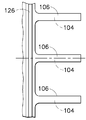
また、図3及び図4を参照すると、アウタレース54は、本体100とエンジン10の周りで円周方向に延びる複数のばね102とを含む。より具体的には、アウタレース54は、複数の第1のばね104と、複数の第2のばね106と、複数の結合部材108とを含む。ばね104及び106は、エンジン10の周りで列の形態で(図4に示す)円周方向に延びる。
3 and 4, the
各第1のばね104は、前端部110と、後端部112と、それらの間で延びる本体114とを含む。各第1のばね前端部110は、アウタレース本体100の下流側面116に結合されて、第1のばね本体114がアウタレース本体100から下流方向に延びるようになる。より具体的には、各第1のばね104は、転動体52から外側に半径方向距離118を置いて取付けられる。各第1のばね後端部112は、環状の区画58内において、アウタレース本体100の下流で対応する結合部材108に結合される。1つの例示的な実施形態では、結合部材108は、第3のばねである。
Each
各第2のばね106は、前端部121と、後端部122と、それらの間で延びる本体124とを含む。各第2のばねの前端部121は、締結具128によって支持フレームに結合されたフランジ126に取付けられて、第2のばねの本体124が支持フレーム44から下流方向に延びるようになる。さらに、締結具128によりフランジ126が支持フレーム44に固定されると、その時アウタレース54は、所定の位置で支持フレーム44に固定される。
Each
各第2のばね106は、転動体52から外側に半径方向距離130を置いて取付けられる。半径方向距離130は、半径方向距離118よりも大きい。各第2のばね後端部122は、環状の区画58内において、アウタレース本体100の下流で対応する結合部材108に結合されて、結合部材108が対応するばね104及び106間で延びかつばね対120を形成するようになる。別の実施形態では、結合部材108は、該結合部材108がばね104及び106に対して比較的弾性があるので、第3のばねとして考えることができる。図2〜図4に示す例示的な実施形態では、アウタレース本体100、第1のばね104、第2のばね106及び結合部材108は、1つの部品として形成される。別の実施形態では、アウタレース本体100、第1のばね104、第2のばね106及び結合部材108は、任意の適当な方法、例えば締結具及び/又は溶接によって取付けられる別個の部品として形成される。
Each
この例示的な実施形態では、各第1のばね本体114は、矩形断面を有し、第1の側面134、第2の側面136、第3の側面138及び第4の側面140を含む。第1の側面134は、第3の側面138にほぼ平行であり、また第2の側面136は、第4の側面140にほぼ平行である。さらに、各第2のばね本体124は、矩形断面を有し、第1の側面142、第2の側面144、第3の側面146及び第4の側面148を含み、第1の側面142は、第3の側面146にほぼ平行であり、また第2の側面144は、第4の側面148にほぼ平行である。各第1のばね本体114の断面積は、前端部110から後端部112までほぼ同一であり、また各第2のばね本体124の断面積は、前端部121から後端部122までほぼ同一である。別の実施形態では、ばね本体114及び124は、多角形断面、円形断面又は楕円形断面を有することができる。
In the exemplary embodiment, each
軸受センタリング部分組立体の第1及び第2のばね本体114及び124は各々、それぞれ内面150及び152を含む。この例示的な実施形態では、各面150及び152はほぼ平面でありかつばね本体114及び124はほぼ平行であるので、軸受センタリング部分組立体のばね104及び106間の距離154は、ほぼ一定に保たれる。別の実施形態では、ばね本体114及び124は、平行でなく、距離154は、前端部110及び121から後端部112及び122まで変化することができる。
The first and
エンジン運転中、この例示的な実施形態では、エンジン100に不釣合いがあると、ファン組立体12(図1に示す)及び軸受組立体46に大きな半径方向の力が加わることになる。より具体的には、エンジン運転中の大きなロータの撓みにより、アウタレース54の半径方向の移動が生じることになる。この半径方向の力は、ばね102を通して支持フレーム44に伝達される。より具体的には、ロータの撓みの結果としてアウタレース本体100に強制的に半径方向外向きの力が加わると、第1のばね104はアウタレース本体100に取付けられているので、半径方向の移動は、第1のばね104に伝達される。
During engine operation, in this exemplary embodiment, if the
その上、ばね104及び106は結合部材108によって結合されているので、半径方向の力は次に、第2のばね106を通して支持フレーム44に伝達される。より具体的には、ばね104及び106は結合部材108によって結合されているので、ロータシャフト42が撓むと、ばね104は、ばね106が半径方向に変位する距離と等しい距離だけ半径方向に変位する。
Moreover, since the
ばね104及び106の撓み量の合計は、アウタレース本体100における全撓み量と等しい。半径方向の全剛性(トータルばね定数)は、
The total deflection amount of the

で与えられる。
ここで、K1は、ばね104のばね定数、K2は、ばね106のばね定数、そしてKtは、アウタレース54のトータルばね定数である。別の実施形態では、結合部材108は、第3のばねであり、K3は、結合部材108のばね定数とすれば、半径方向のトータルばね定数は、
Given in.
Here, K 1 is the spring constant of the
によって与えられる。 Given by.
第1のばね104及び第2のばね106は、それぞれエンジン10の周りで列160及び162の形態で円周方向に延びる。より具体的には、ばね104及び106は、図4に示すように、各第1のばね104が各対応する第2のばね106に対して半径方向に整列しかつ各対応する結合部材108によって第2のばね106に結合されるように、円周方向に配向される。その結果、アウタレース本体100を回転防止していない場合には、円周方向の力がアウタレース本体100から伝達された時に、ばね104及び106の両方には曲げが生じ、等しい量だけ長さが減少する。円周方向の力は、レース54と支持スリーブ70との間の半径方向ギャップ75が消滅又は最低になるほどロータ不釣合い荷重が大きい時に、発生する。このことにより、転動体52の軸受インナレース面92上での正味の軸方向移動すなわち変位が実質的にゼロに等しくなるようになる。
さらに、ばね102は直列に結合されているので、ばね104及び106は、所定の系剛性において、各ばねの撓みが全撓みの半分であることから、直列結合していないばね(図示せず)よりも応力がおよそ50%少なくなる。このことにより、所定のロータ不釣合い荷重に対してより長い疲労寿命が可能になる。
Furthermore, since the
上記のロータ組立体は、コスト効果がありかつ高い信頼性がある。ロータ組立体は、エンジン支持フレーム及び軸受組立体への動的半径方向力を減少させ、その結果、エンジンの有効寿命及び性能を高めることができる。さらに、ばねのトータルばね定数を指定することにより、構造的に調整し、特定の飛行ポイントにおける動的応答を低下させることが可能になる。このことにより、エンジンの長い有効寿命及び向上した性能が得られる。 The above rotor assembly is cost effective and highly reliable. The rotor assembly can reduce dynamic radial forces on the engine support frame and bearing assembly, thereby increasing the useful life and performance of the engine. Furthermore, by specifying the total spring constant of the spring, it is possible to adjust structurally and reduce the dynamic response at a specific flight point. This provides a long useful life and improved performance of the engine.
本発明を様々な特定の実施形態に関して説明してきたが、本発明が特許請求の範囲の技術思想及び技術的範囲内の変更で実施することができることは、当業者には明らかであろう。なお、特許請求の範囲に記載された符号は、理解容易のためであってなんら発明の技術的範囲を実施例に限縮するものではない。 While the invention has been described in terms of various specific embodiments, those skilled in the art will recognize that the invention can be practiced with modification within the spirit and scope of the claims. In addition, the code | symbol described in the claim is for easy understanding, and does not limit the technical scope of an invention to an Example at all.
42 ロータシャフト
44 支持フレーム
46 軸受組立体
52 転動体
54 アウタレース
56 インナレース
58 環状の密封区画
70 支持スリーブ
102 ばね
104 第1のばね
106 第2のばね
108 結合部材
114 第1のばね本体
120 ばね対
124 第2のばね本体
126 フランジ
42
Claims (10)
インナレース(56)と、
アウタレース組立体(54)と、
転動体(52)と、を含み、前記アウタレース組立体(54)が、
本体(100)と、
前記本体に取付けられた複数の第1のばね(104)と、
対応する1つと各前記第1のばねが半径方向に整列してばね対(120)を形成した、複数の第2のばね(106)と、
その各々が前記ばね対の第1のばね(104)の第1の端部(112)と第2のばね(106)の第1の端部(122)との間で延びかつそれらを結合する複数の結合部材(108)と、
それに対して前記第2のばねが取付けられた、フランジ(126)と、
を含み、
前記結合部材(108)のそれぞれから前記第1及び第2のばね(104、106)のそれぞれにばね力が伝達されることを特徴とする、軸受組立体。A bearing assembly (46) for a gas turbine engine (40) comprising:
Inner race (56),
Outer race assembly (54);
A rolling element (52), wherein the outer race assembly (54) comprises:
A main body (100);
A plurality of first springs (104) attached to the body;
A plurality of second springs (106), wherein a corresponding one and each said first spring is radially aligned to form a spring pair (120);
Each extends between and couples the first end (112) of the first spring (104) of the spring pair and the first end (122) of the second spring (106). A plurality of coupling members (108);
A flange (126) to which the second spring is attached;
Only including,
A bearing assembly , wherein a spring force is transmitted from each of the coupling members (108) to each of the first and second springs (104, 106) .
The bearing assembly (46) of any preceding claim, wherein each first spring (104) includes a rectangular cross-section and each second spring (106) includes a rectangular cross-section.
Each of the first springs (104) includes a first side (134), a second side (136), a third side (138), and a fourth side (140), the first side Is parallel to the third side, the second side is parallel to the fourth side, and each second spring (106) is connected to the first side (142), the second side Including a side surface (144), a third side surface (146), and a fourth side surface (148), wherein the first side surface is parallel to the third side surface, and the second side surface is the fourth side surface. The bearing assembly (46) of claim 3, wherein the bearing assembly (46) is parallel to
The bearing assembly (46) of claim 1, wherein each first spring (104) and second spring (106) of the spring pair (120) is parallel .
Applications Claiming Priority (2)
| Application Number | Priority Date | Filing Date | Title |
|---|---|---|---|
| US10/928,940 | 2004-08-27 | ||
| US10/928,940 US7384199B2 (en) | 2004-08-27 | 2004-08-27 | Apparatus for centering rotor assembly bearings |
Publications (2)
| Publication Number | Publication Date |
|---|---|
| JP2006077764A JP2006077764A (en) | 2006-03-23 |
| JP4860964B2 true JP4860964B2 (en) | 2012-01-25 |
Family
ID=35219273
Family Applications (1)
| Application Number | Title | Priority Date | Filing Date |
|---|---|---|---|
| JP2005245801A Expired - Fee Related JP4860964B2 (en) | 2004-08-27 | 2005-08-26 | Apparatus for centering rotor assembly bearings |
Country Status (3)
| Country | Link |
|---|---|
| US (1) | US7384199B2 (en) |
| EP (1) | EP1630357A3 (en) |
| JP (1) | JP4860964B2 (en) |
Families Citing this family (45)
| Publication number | Priority date | Publication date | Assignee | Title |
|---|---|---|---|---|
| DE102008037786A1 (en) * | 2007-09-18 | 2009-03-26 | Schaeffler Kg | Uniform center support for bearing subassembly for use in propel shaft or drive shaft, has plastic-bearing housing for bearing and plastic-support insert for support |
| US8267650B2 (en) * | 2007-10-30 | 2012-09-18 | Honeywell International Inc. | Sequential stiffness support for bearing assemblies and method of fabrication |
| FR2926604B1 (en) * | 2008-01-23 | 2010-03-26 | Snecma | CENTERING A WORKPIECE WITHIN A ROTOR SHAFT IN A TURBOMACHINE |
| US8182156B2 (en) * | 2008-07-31 | 2012-05-22 | General Electric Company | Nested bearing cages |
| FR2951232B1 (en) * | 2009-10-08 | 2017-06-09 | Snecma | DEVICE FOR CENTERING AND GUIDING ROTATION OF A TURBOMACHINE SHAFT |
| FR2960907B1 (en) * | 2010-06-02 | 2012-07-27 | Snecma | BEARING BEARING FOR AIRCRAFT TURBOJET ENGINE WITH IMPROVED AXIAL RETENTION MEANS FOR ITS OUTER RING |
| US8702377B2 (en) | 2010-06-23 | 2014-04-22 | Honeywell International Inc. | Gas turbine engine rotor tip clearance and shaft dynamics system and method |
| US8747054B2 (en) | 2011-01-24 | 2014-06-10 | United Technologies Corporation | Bearing system for gas turbine engine |
| US8834095B2 (en) * | 2011-06-24 | 2014-09-16 | United Technologies Corporation | Integral bearing support and centering spring assembly for a gas turbine engine |
| US8992161B2 (en) | 2011-08-26 | 2015-03-31 | Honeywell International Inc. | Gas turbine engines including broadband damping systems and methods for producing the same |
| US9046001B2 (en) | 2011-08-29 | 2015-06-02 | Honeywell International Inc. | Annular bearing support dampers, gas turbine engines including the same, and methods for the manufacture thereof |
| US8727632B2 (en) | 2011-11-01 | 2014-05-20 | General Electric Company | Bearing support apparatus for a gas turbine engine |
| US9297438B2 (en) | 2012-01-25 | 2016-03-29 | Honeywell International Inc. | Three parameter damper anisotropic vibration isolation mounting assembly |
| US10001028B2 (en) | 2012-04-23 | 2018-06-19 | General Electric Company | Dual spring bearing support housing |
| CA2870683C (en) * | 2012-04-25 | 2017-03-28 | General Electric Company | Apparatus and method for assembling a damper bearing assembly |
| DE102012208744A1 (en) * | 2012-05-24 | 2013-11-28 | Schaeffler Technologies AG & Co. KG | roller bearing |
| WO2014051657A1 (en) * | 2012-09-25 | 2014-04-03 | United Technologies Corporation | Turbomachine bearing support structure |
| FR2997996B1 (en) * | 2012-11-12 | 2015-01-09 | Snecma | AIR TUBE SUPPORT SUPPORT IN A TURBOMACHINE |
| FR2997997B1 (en) * | 2012-11-12 | 2014-12-26 | Snecma | AIR TUBE SUPPORT SUPPORT IN A TURBOMACHINE |
| DE102012221369A1 (en) | 2012-11-22 | 2014-05-22 | Schaeffler Technologies Gmbh & Co. Kg | roller bearing |
| EP2959116B1 (en) * | 2013-02-24 | 2018-11-28 | Rolls-Royce Corporation | Shaft displacement control |
| EP2978954A4 (en) * | 2013-03-28 | 2016-11-30 | United Technologies Corp | Rear bearing sleeve for gas turbine auxiliary power unit |
| EP3011194B1 (en) * | 2013-06-21 | 2021-08-25 | Raytheon Technologies Corporation | Nonlinear rolling bearing radial support stiffness |
| WO2015076902A2 (en) * | 2013-09-09 | 2015-05-28 | United Technologies Corporation | Reservoir egress fluid coupler |
| FR3013760B1 (en) * | 2013-11-26 | 2015-12-25 | Snecma | DEVICE FOR THE CENTERING AND ROTATION GUIDING OF A TURBOMACHINE SHAFT COMPRISING IMPROVED MEANS FOR RETAINING EXTERNAL BEARING RING |
| WO2015130370A2 (en) * | 2013-12-20 | 2015-09-03 | United Technologies Corporation | Bearing supports |
| PL406855A1 (en) | 2014-01-15 | 2015-07-20 | General Electric Company | An unit immobilizing a bearing and method for assembling it |
| US9784128B2 (en) * | 2014-04-24 | 2017-10-10 | United Technologies Corporation | Systems and methods for engine bearings |
| DE102014208040B4 (en) | 2014-04-29 | 2019-09-12 | MTU Aero Engines AG | Bearing cage and bearing device with such a bearing cage and method for forming, repairing and / or replacing such a bearing cage |
| US9933012B1 (en) | 2015-02-09 | 2018-04-03 | United Technologies Corporation | Bearing centering spring with integral outer rings |
| EP3115564A1 (en) * | 2015-07-09 | 2017-01-11 | General Electric Company | Bearing housing and related bearing assembly for a gas turbine engine |
| US9909451B2 (en) | 2015-07-09 | 2018-03-06 | General Electric Company | Bearing assembly for supporting a rotor shaft of a gas turbine engine |
| US9702404B2 (en) | 2015-10-28 | 2017-07-11 | United Technologies Corporation | Integral centering spring and bearing support and method of supporting multiple damped bearings |
| US10041534B2 (en) * | 2016-02-08 | 2018-08-07 | General Electric Company | Bearing outer race retention during high load events |
| FR3066550B1 (en) * | 2017-05-18 | 2019-07-12 | Safran Aircraft Engines | DEVICE FOR THE CENTERING AND ROTATION GUIDING OF A TURBOMACHINE TREE COMPRISING AXIAL RETAINING RINGS OF EXTERNAL BEARING RING |
| US10823002B2 (en) * | 2018-05-15 | 2020-11-03 | General Electric Company | Variable stiffness static structure |
| FR3086020B1 (en) * | 2018-09-13 | 2020-12-25 | Safran Aircraft Engines | AXIAL RETAINING SYSTEM OF A BEARING BUSH |
| FR3088672B1 (en) * | 2018-11-16 | 2020-12-18 | Safran Aircraft Engines | DEVICE FOR CENTERING AND GUIDING IN ROTATION OF A ROTATING PART WITH INTERLACED ARMS |
| US10935080B2 (en) * | 2019-03-14 | 2021-03-02 | Raytheon Technologies Corporation | Extended housing sleeve with stiffening ring feature |
| FR3094051B1 (en) | 2019-03-18 | 2021-04-23 | Skf Aerospace France | Squirrel-type cage ring in composite bi-material and metal, and rolling element bearing assembly equipped with such a ring |
| US10844746B2 (en) * | 2019-03-29 | 2020-11-24 | Pratt & Whitney Canada Corp. | Bearing housing |
| US10794222B1 (en) | 2019-08-14 | 2020-10-06 | General Electric Company | Spring flower ring support assembly for a bearing |
| US11118629B2 (en) | 2019-12-11 | 2021-09-14 | Raytheon Technologies Corporation | Curved beam centering spring for a thrust bearing |
| US11639304B2 (en) | 2020-02-07 | 2023-05-02 | Raytheon Technologies Corporation | Method of fabricating a glass-ceramic matrix composite |
| US11828235B2 (en) | 2020-12-08 | 2023-11-28 | General Electric Company | Gearbox for a gas turbine engine utilizing shape memory alloy dampers |
Family Cites Families (35)
| Publication number | Priority date | Publication date | Assignee | Title |
|---|---|---|---|---|
| GB595346A (en) * | 1941-05-07 | 1947-12-03 | Hayne Constant | Improvements relating to bearings of internal combustion gas turbines, turbine type gas compressors, and like high speed machinery |
| US3460873A (en) | 1967-10-26 | 1969-08-12 | Bendix Corp | Bearing overload protection means |
| US3738719A (en) | 1970-08-04 | 1973-06-12 | Snecma | Ball bearing |
| US4214796A (en) | 1978-10-19 | 1980-07-29 | General Electric Company | Bearing assembly with multiple squeeze film damper apparatus |
| GB2043833B (en) | 1979-03-17 | 1982-11-10 | Rolls Royce | Rotor assembly |
| GB2079402B (en) | 1980-06-27 | 1984-02-22 | Rolls Royce | System for supporting a rotor in conditions of dynamic imbalance |
| US4337982A (en) * | 1980-12-11 | 1982-07-06 | United Technologies Corporation | Friction damper |
| US4400098A (en) | 1980-12-15 | 1983-08-23 | Ransome Hoffmann Pollard Limited | Bearing arrangements |
| US4453890A (en) | 1981-06-18 | 1984-06-12 | General Electric Company | Blading system for a gas turbine engine |
| US4429923A (en) * | 1981-12-08 | 1984-02-07 | United Technologies Corporation | Bearing support structure |
| US4527912A (en) | 1984-05-31 | 1985-07-09 | General Motors Corporation | Squeeze film damper |
| JPS61211519A (en) | 1985-03-13 | 1986-09-19 | Nissan Motor Co Ltd | Bearing structure of turbocharger |
| US4872767A (en) | 1985-04-03 | 1989-10-10 | General Electric Company | Bearing support |
| DE3532456A1 (en) * | 1985-09-11 | 1987-03-19 | Mtu Muenchen Gmbh | INTERMEDIATE SHAFT (INTERSHAFT) BEARING WITH SQUEEZE FILM DAMPING WITH OR WITHOUT SQUIRREL CAGE |
| JPH0627458Y2 (en) * | 1985-09-21 | 1994-07-27 | 日産自動車株式会社 | Center bearing support device for propeller shaft |
| JP2521717B2 (en) * | 1986-06-10 | 1996-08-07 | 株式会社 ブリヂストン | Center bearing |
| US4687346A (en) | 1986-09-02 | 1987-08-18 | United Technologies Corporation | Low profile bearing support structure |
| GB8630754D0 (en) | 1986-12-23 | 1987-02-04 | Rolls Royce Plc | Turbofan gas turbine engine |
| US4971457A (en) | 1989-10-04 | 1990-11-20 | United Technologies Corporation | Fluid damper |
| US5088840A (en) * | 1990-07-26 | 1992-02-18 | United Technologies Corporation | Dashpot damper |
| US5161940A (en) * | 1991-06-21 | 1992-11-10 | Pratt & Whitney Canada, Inc. | Annular support |
| US5433584A (en) | 1994-05-05 | 1995-07-18 | Pratt & Whitney Canada, Inc. | Bearing support housing |
| US5603602A (en) | 1994-08-08 | 1997-02-18 | Pratt & Whitney Canada Inc. | Pressurized ball bearing assemblies |
| FR2749883B1 (en) | 1996-06-13 | 1998-07-31 | Snecma | METHOD AND BEARING SUPPORT FOR MAINTAINING A TURBOMOTOR FOR AN AIRCRAFT IN OPERATION AFTER AN ACCIDENTAL BALANCE ON A ROTOR |
| US6002778A (en) | 1996-08-07 | 1999-12-14 | Lord Corporation | Active structural control system and method including active vibration absorbers (AVAS) |
| US5735666A (en) | 1996-12-31 | 1998-04-07 | General Electric Company | System and method of controlling thrust forces on a thrust bearing in a rotating structure of a gas turbine engine |
| GB2322165B (en) | 1997-02-15 | 2001-02-28 | Rolls Royce Plc | Ducted fan gas turbine engine |
| GB2322914B (en) | 1997-03-05 | 2000-05-24 | Rolls Royce Plc | Ducted fan gas turbine engine |
| GB2326679B (en) | 1997-06-25 | 2000-07-26 | Rolls Royce Plc | Ducted fan gas turbine engine |
| JPH1182521A (en) * | 1997-08-29 | 1999-03-26 | Totsuku Bearing Kk | Bearing |
| US6240719B1 (en) * | 1998-12-09 | 2001-06-05 | General Electric Company | Fan decoupler system for a gas turbine engine |
| JP4014021B2 (en) * | 1998-12-10 | 2007-11-28 | 株式会社ショーワ | Propeller shaft support structure |
| US6099165A (en) | 1999-01-19 | 2000-08-08 | Pratt & Whitney Canada Corp. | Soft bearing support |
| US6443698B1 (en) | 2001-01-26 | 2002-09-03 | General Electric Company | Method and apparatus for centering rotor assembly damper bearings |
| US6540483B2 (en) * | 2001-08-27 | 2003-04-01 | General Electric Company | Methods and apparatus for bearing outer race axial retention |
-
2004
- 2004-08-27 US US10/928,940 patent/US7384199B2/en active Active
-
2005
- 2005-08-25 EP EP05255230A patent/EP1630357A3/en not_active Withdrawn
- 2005-08-26 JP JP2005245801A patent/JP4860964B2/en not_active Expired - Fee Related
Also Published As
| Publication number | Publication date |
|---|---|
| US20060045404A1 (en) | 2006-03-02 |
| EP1630357A3 (en) | 2011-06-29 |
| EP1630357A2 (en) | 2006-03-01 |
| JP2006077764A (en) | 2006-03-23 |
| US7384199B2 (en) | 2008-06-10 |
Similar Documents
| Publication | Publication Date | Title |
|---|---|---|
| JP4860964B2 (en) | Apparatus for centering rotor assembly bearings | |
| US6443698B1 (en) | Method and apparatus for centering rotor assembly damper bearings | |
| US6413046B1 (en) | Method and apparatus for centering rotor assembly damper bearings | |
| JP5830177B2 (en) | Series bearing support for a gas turbine engine | |
| EP3112588B1 (en) | Rotor damper | |
| EP3232072B1 (en) | Centering spring and damper assembly | |
| US7731426B2 (en) | Rotor supports and systems | |
| US10001028B2 (en) | Dual spring bearing support housing | |
| CA3024506C (en) | Turbine bearing support | |
| US20030039538A1 (en) | Methods and apparatus for bearing outer race axial retention | |
| JP2004190679A (en) | Method and apparatus for assembling bearing assembly | |
| CN104246145A (en) | Apparatus and method for assembling a damper bearing assembly | |
| GB2058245A (en) | Alleviating abnormal loadings in bearings | |
| EP3205819A1 (en) | Gas turbine engine with ring damper | |
| US20200096041A1 (en) | Bearing housing with damping arrangement | |
| US20150308510A1 (en) | Systems and methods for engine bearings | |
| KR20130004303A (en) | Flexible rear bearing mounting, having an abutment, for a turbine engine | |
| JP2018087633A (en) | Landing bearing assembly and rotary machine equipped with such assembly | |
| CN110701188A (en) | Flexible reed axial protection bearing for magnetic bearing | |
| US10746050B2 (en) | Variable stiffness bearing suspension device | |
| US20240093638A1 (en) | Improved ferrule for counter-rotating turbine impeller | |
| US20160245089A1 (en) | Bladed disc | |
| EP3825566B1 (en) | Bearing compartment arrangement with thrust sensing assembly. |
Legal Events
| Date | Code | Title | Description |
|---|---|---|---|
| A621 | Written request for application examination |
Free format text: JAPANESE INTERMEDIATE CODE: A621 Effective date: 20080821 |
|
| A977 | Report on retrieval |
Free format text: JAPANESE INTERMEDIATE CODE: A971007 Effective date: 20100909 |
|
| A131 | Notification of reasons for refusal |
Free format text: JAPANESE INTERMEDIATE CODE: A131 Effective date: 20100914 |
|
| A601 | Written request for extension of time |
Free format text: JAPANESE INTERMEDIATE CODE: A601 Effective date: 20101210 |
|
| RD02 | Notification of acceptance of power of attorney |
Free format text: JAPANESE INTERMEDIATE CODE: A7422 Effective date: 20101210 |
|
| RD04 | Notification of resignation of power of attorney |
Free format text: JAPANESE INTERMEDIATE CODE: A7424 Effective date: 20101210 |
|
| A602 | Written permission of extension of time |
Free format text: JAPANESE INTERMEDIATE CODE: A602 Effective date: 20101215 |
|
| A521 | Request for written amendment filed |
Free format text: JAPANESE INTERMEDIATE CODE: A523 Effective date: 20110314 |
|
| A131 | Notification of reasons for refusal |
Free format text: JAPANESE INTERMEDIATE CODE: A131 Effective date: 20110621 |
|
| A521 | Request for written amendment filed |
Free format text: JAPANESE INTERMEDIATE CODE: A523 Effective date: 20110921 |
|
| TRDD | Decision of grant or rejection written | ||
| A01 | Written decision to grant a patent or to grant a registration (utility model) |
Free format text: JAPANESE INTERMEDIATE CODE: A01 Effective date: 20111011 |
|
| A01 | Written decision to grant a patent or to grant a registration (utility model) |
Free format text: JAPANESE INTERMEDIATE CODE: A01 |
|
| A61 | First payment of annual fees (during grant procedure) |
Free format text: JAPANESE INTERMEDIATE CODE: A61 Effective date: 20111104 |
|
| R150 | Certificate of patent or registration of utility model |
Free format text: JAPANESE INTERMEDIATE CODE: R150 |
|
| FPAY | Renewal fee payment (event date is renewal date of database) |
Free format text: PAYMENT UNTIL: 20141111 Year of fee payment: 3 |
|
| R250 | Receipt of annual fees |
Free format text: JAPANESE INTERMEDIATE CODE: R250 |
|
| R250 | Receipt of annual fees |
Free format text: JAPANESE INTERMEDIATE CODE: R250 |
|
| R250 | Receipt of annual fees |
Free format text: JAPANESE INTERMEDIATE CODE: R250 |
|
| LAPS | Cancellation because of no payment of annual fees |