JP4857360B2 - Visual processing device, visual processing method, television, portable information terminal, camera and processor - Google Patents
Visual processing device, visual processing method, television, portable information terminal, camera and processor Download PDFInfo
- Publication number
- JP4857360B2 JP4857360B2 JP2009113828A JP2009113828A JP4857360B2 JP 4857360 B2 JP4857360 B2 JP 4857360B2 JP 2009113828 A JP2009113828 A JP 2009113828A JP 2009113828 A JP2009113828 A JP 2009113828A JP 4857360 B2 JP4857360 B2 JP 4857360B2
- Authority
- JP
- Japan
- Prior art keywords
- signal
- gain
- image
- unit
- value
- Prior art date
- Legal status (The legal status is an assumption and is not a legal conclusion. Google has not performed a legal analysis and makes no representation as to the accuracy of the status listed.)
- Active
Links
Images


Classifications
-
- G—PHYSICS
- G09—EDUCATION; CRYPTOGRAPHY; DISPLAY; ADVERTISING; SEALS
- G09G—ARRANGEMENTS OR CIRCUITS FOR CONTROL OF INDICATING DEVICES USING STATIC MEANS TO PRESENT VARIABLE INFORMATION
- G09G5/00—Control arrangements or circuits for visual indicators common to cathode-ray tube indicators and other visual indicators
- G09G5/02—Control arrangements or circuits for visual indicators common to cathode-ray tube indicators and other visual indicators characterised by the way in which colour is displayed
- G09G5/04—Control arrangements or circuits for visual indicators common to cathode-ray tube indicators and other visual indicators characterised by the way in which colour is displayed using circuits for interfacing with colour displays
-
- G—PHYSICS
- G09—EDUCATION; CRYPTOGRAPHY; DISPLAY; ADVERTISING; SEALS
- G09G—ARRANGEMENTS OR CIRCUITS FOR CONTROL OF INDICATING DEVICES USING STATIC MEANS TO PRESENT VARIABLE INFORMATION
- G09G5/00—Control arrangements or circuits for visual indicators common to cathode-ray tube indicators and other visual indicators
- G09G5/02—Control arrangements or circuits for visual indicators common to cathode-ray tube indicators and other visual indicators characterised by the way in which colour is displayed
- G09G5/06—Control arrangements or circuits for visual indicators common to cathode-ray tube indicators and other visual indicators characterised by the way in which colour is displayed using colour palettes, e.g. look-up tables
-
- H—ELECTRICITY
- H04—ELECTRIC COMMUNICATION TECHNIQUE
- H04N—PICTORIAL COMMUNICATION, e.g. TELEVISION
- H04N21/00—Selective content distribution, e.g. interactive television or video on demand [VOD]
- H04N21/40—Client devices specifically adapted for the reception of or interaction with content, e.g. set-top-box [STB]; Operations thereof
- H04N21/43—Processing of content or additional data, e.g. demultiplexing additional data from a digital video stream; Elementary client operations, e.g. monitoring of home network or synchronising decoder's clock; Client middleware
- H04N21/431—Generation of visual interfaces for content selection or interaction; Content or additional data rendering
- H04N21/4318—Generation of visual interfaces for content selection or interaction; Content or additional data rendering by altering the content in the rendering process, e.g. blanking, blurring or masking an image region
-
- H—ELECTRICITY
- H04—ELECTRIC COMMUNICATION TECHNIQUE
- H04N—PICTORIAL COMMUNICATION, e.g. TELEVISION
- H04N21/00—Selective content distribution, e.g. interactive television or video on demand [VOD]
- H04N21/40—Client devices specifically adapted for the reception of or interaction with content, e.g. set-top-box [STB]; Operations thereof
- H04N21/43—Processing of content or additional data, e.g. demultiplexing additional data from a digital video stream; Elementary client operations, e.g. monitoring of home network or synchronising decoder's clock; Client middleware
- H04N21/44—Processing of video elementary streams, e.g. splicing a video clip retrieved from local storage with an incoming video stream, rendering scenes according to MPEG-4 scene graphs
- H04N21/44008—Processing of video elementary streams, e.g. splicing a video clip retrieved from local storage with an incoming video stream, rendering scenes according to MPEG-4 scene graphs involving operations for analysing video streams, e.g. detecting features or characteristics in the video stream
-
- H—ELECTRICITY
- H04—ELECTRIC COMMUNICATION TECHNIQUE
- H04N—PICTORIAL COMMUNICATION, e.g. TELEVISION
- H04N21/00—Selective content distribution, e.g. interactive television or video on demand [VOD]
- H04N21/80—Generation or processing of content or additional data by content creator independently of the distribution process; Content per se
- H04N21/83—Generation or processing of protective or descriptive data associated with content; Content structuring
- H04N21/84—Generation or processing of descriptive data, e.g. content descriptors
-
- H—ELECTRICITY
- H04—ELECTRIC COMMUNICATION TECHNIQUE
- H04N—PICTORIAL COMMUNICATION, e.g. TELEVISION
- H04N5/00—Details of television systems
- H04N5/44—Receiver circuitry for the reception of television signals according to analogue transmission standards
- H04N5/57—Control of contrast or brightness
-
- H—ELECTRICITY
- H04—ELECTRIC COMMUNICATION TECHNIQUE
- H04N—PICTORIAL COMMUNICATION, e.g. TELEVISION
- H04N9/00—Details of colour television systems
- H04N9/64—Circuits for processing colour signals
- H04N9/643—Hue control means, e.g. flesh tone control
-
- H—ELECTRICITY
- H04—ELECTRIC COMMUNICATION TECHNIQUE
- H04N—PICTORIAL COMMUNICATION, e.g. TELEVISION
- H04N9/00—Details of colour television systems
- H04N9/64—Circuits for processing colour signals
- H04N9/68—Circuits for processing colour signals for controlling the amplitude of colour signals, e.g. automatic chroma control circuits
-
- G—PHYSICS
- G09—EDUCATION; CRYPTOGRAPHY; DISPLAY; ADVERTISING; SEALS
- G09G—ARRANGEMENTS OR CIRCUITS FOR CONTROL OF INDICATING DEVICES USING STATIC MEANS TO PRESENT VARIABLE INFORMATION
- G09G2320/00—Control of display operating conditions
- G09G2320/02—Improving the quality of display appearance
- G09G2320/0242—Compensation of deficiencies in the appearance of colours
-
- G—PHYSICS
- G09—EDUCATION; CRYPTOGRAPHY; DISPLAY; ADVERTISING; SEALS
- G09G—ARRANGEMENTS OR CIRCUITS FOR CONTROL OF INDICATING DEVICES USING STATIC MEANS TO PRESENT VARIABLE INFORMATION
- G09G2320/00—Control of display operating conditions
- G09G2320/02—Improving the quality of display appearance
- G09G2320/0285—Improving the quality of display appearance using tables for spatial correction of display data
-
- G—PHYSICS
- G09—EDUCATION; CRYPTOGRAPHY; DISPLAY; ADVERTISING; SEALS
- G09G—ARRANGEMENTS OR CIRCUITS FOR CONTROL OF INDICATING DEVICES USING STATIC MEANS TO PRESENT VARIABLE INFORMATION
- G09G2320/00—Control of display operating conditions
- G09G2320/06—Adjustment of display parameters
- G09G2320/066—Adjustment of display parameters for control of contrast
-
- G—PHYSICS
- G09—EDUCATION; CRYPTOGRAPHY; DISPLAY; ADVERTISING; SEALS
- G09G—ARRANGEMENTS OR CIRCUITS FOR CONTROL OF INDICATING DEVICES USING STATIC MEANS TO PRESENT VARIABLE INFORMATION
- G09G2320/00—Control of display operating conditions
- G09G2320/06—Adjustment of display parameters
- G09G2320/0673—Adjustment of display parameters for control of gamma adjustment, e.g. selecting another gamma curve
-
- H—ELECTRICITY
- H04—ELECTRIC COMMUNICATION TECHNIQUE
- H04N—PICTORIAL COMMUNICATION, e.g. TELEVISION
- H04N21/00—Selective content distribution, e.g. interactive television or video on demand [VOD]
- H04N21/40—Client devices specifically adapted for the reception of or interaction with content, e.g. set-top-box [STB]; Operations thereof
- H04N21/41—Structure of client; Structure of client peripherals
- H04N21/426—Internal components of the client ; Characteristics thereof
-
- H—ELECTRICITY
- H04—ELECTRIC COMMUNICATION TECHNIQUE
- H04N—PICTORIAL COMMUNICATION, e.g. TELEVISION
- H04N9/00—Details of colour television systems
- H04N9/64—Circuits for processing colour signals
- H04N9/68—Circuits for processing colour signals for controlling the amplitude of colour signals, e.g. automatic chroma control circuits
- H04N9/69—Circuits for processing colour signals for controlling the amplitude of colour signals, e.g. automatic chroma control circuits for modifying the colour signals by gamma correction
Description
本発明は、視覚処理装置、表示装置および集積回路に関し、特に、画像のコントラストを調整する視覚処理装置、表示装置および集積回路に関する。 The present invention relates to a visual processing device, a display device, and an integrated circuit, and more particularly to a visual processing device, a display device, and an integrated circuit that adjust the contrast of an image.
従来のカラーテレビジョン受像機では、画像の明暗を調整するためにコントラスト調整を行っていた。
コントラスト調整では、色バランスを崩さないように、RGB信号を輝度信号と色度信号に分離し、輝度信号のコントラストを調整するようにしていた。
また、輝度信号レベルを大きくした部分では、色が薄く見え、逆に輝度信号レベルを小さくした部分では色が濃く見えて不自然な状態で出力されるので、輝度信号レベルの変化に対応するように色度信号のレベルも増減させるようにしていた。
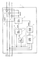
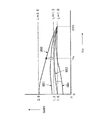
従来の表示装置のコントラスト調整回路について図52を用いて説明する。図52は従来の表示装置のコントラスト調整回路の構成を示すブロック図である。図52において、Yマトリクス100はR、G、B信号を輝度信号Yaに変換するものである。同様に、R−Yマトリクス101はR、G、B信号を色度信号であるR−Yに、B−Yマトリクス102はR、G、B信号を色度信号であるB−Yに変換するものである。ガンマ補正回路104は輝度信号Yaのリニアリティを輝度信号Ybに変換するものである。また、ガンマ補正回路104はルックアップテーブル(以下、「LUT」という)より構成され、例えば図53に示すような、ガンマ変換特性を有するテーブル値が書き込まれている。ここで、横軸が入力Ya、縦軸が出力Ybである。
In a conventional color television receiver, contrast adjustment is performed to adjust the contrast of an image.
In contrast adjustment, the RGB signal is separated into a luminance signal and a chromaticity signal so as not to break the color balance, and the contrast of the luminance signal is adjusted.
Also, when the luminance signal level is increased, the color appears lighter, whereas when the luminance signal level is decreased, the color appears darker and output in an unnatural state. In addition, the level of the chromaticity signal is also increased or decreased.
A contrast adjustment circuit of a conventional display device will be described with reference to FIG. FIG. 52 is a block diagram showing a configuration of a contrast adjustment circuit of a conventional display device. In FIG. 52, a
除算回路105は、輝度信号Ybを輝度信号Yaで除算し、変換率Yb/Yaを得る。係数器106は、変換率Yb/Yaと係数Kとの演算により、色信号を増幅する変換係数Kc=1+K(Yb/Ya−1)を得る。ここで、係数Kを変更することで、色信号の増加を抑えることができる。また、乗算器107、108は、R−Yマトリクス101の出力、B−Yマトリクス102の出力に変換係数Kcが乗算され、輝度コントラスト調整に対応した色度(R−Y)信号および色度(B−Y)信号が生成される(例えば特許文献1)。
The
しかしながら、上記構成のコントラスト調整回路では、色度信号に対して、輝度信号が除算回路により除算された後(輝度信号を除算する処理は、演算処理数が多いため、除算結果が出力されるまで時間がかかるので、遅延が発生する。)、乗算器により乗算を行うための係数が取得され、取得された係数を色度信号に乗算するという処理を行うことになるので、出力される輝度信号と出力される色度信号との出力タイミングがずれたものとなり、別途、出力輝度信号と出力色度信号とのタイミングを合わせるため、遅延手段等が必要となるという課題がある。
本発明が解決しようとする課題は、入力された画像信号に対して、高性能なコントラスト調整を実施することができ、かつ、出力される画像信号の出力タイミングにズレが生じない視覚処理装置を実現することである。また、その視覚処理装置を備える表示装置および、その視覚処理装置を含む集積回路を実現することである。
However, in the contrast adjustment circuit having the above-described configuration, after the luminance signal is divided by the divider circuit with respect to the chromaticity signal (the processing for dividing the luminance signal has a large number of arithmetic processing steps, so that the division result is output). Since it takes time, a delay occurs.) A coefficient for performing multiplication is acquired by the multiplier, and a process of multiplying the acquired coefficient by the chromaticity signal is performed. The output timings of the output chromaticity signal and the output chromaticity signal are shifted, and there is a problem that a delay means or the like is required to match the timing of the output luminance signal and the output chromaticity signal separately.
A problem to be solved by the present invention is to provide a visual processing device that can perform high-performance contrast adjustment on an input image signal and that does not cause a deviation in the output timing of the output image signal. Is to realize. Another object is to realize a display device including the visual processing device and an integrated circuit including the visual processing device.
第1の発明は、入力された画像信号を補正して出力する視覚処理装置であって、視覚処理部と、補正部とを備える。視覚処理部は、画像信号に対して所定のゲイン特性を有する第1ゲイン信号を出力する。補正部は、第1ゲイン信号に基づいて画像信号を補正する。
この視覚処理装置では、画像信号に対して所定のゲイン特性を有する第1ゲイン信号が視覚処理部により出力され、第1ゲイン信号に基づいて、視覚処理装置に入力された画像信号が補正されるので、高性能な補正処理を簡易な構成で実現することができる。つまり、画像信号を補正するのに、直接階調補正するのではなく、ゲイン信号により補正するので、簡易な処理で画像信号の補正を行うことができ、例えば、ハードウェアで構成する場合等に回路規模を削減することができる。また、ゲイン信号による補正により画像信号の補正を実現するので、補正後の出力画像信号の出力タイミングを容易に合わせることができる。
A first invention is a visual processing device that corrects and outputs an input image signal, and includes a visual processing unit and a correction unit. The visual processing unit outputs a first gain signal having a predetermined gain characteristic with respect to the image signal. The correction unit corrects the image signal based on the first gain signal.
In this visual processing device, a first gain signal having a predetermined gain characteristic with respect to the image signal is output by the visual processing unit, and the image signal input to the visual processing device is corrected based on the first gain signal. Therefore, high-performance correction processing can be realized with a simple configuration. In other words, the correction of the image signal is not performed directly by the gradation correction, but by the gain signal, so that the image signal can be corrected by a simple process. For example, when it is configured by hardware The circuit scale can be reduced. Further, since the correction of the image signal is realized by the correction by the gain signal, the output timing of the output image signal after the correction can be easily adjusted.
第2の発明は、第1の発明であって、設定された所定の制限値で第1ゲイン信号を制限して第2ゲイン信号を出力するゲイン制限部をさらに備える。補正部は、第2ゲイン信号に基づいて画像信号を補正する。
このような構成により、高彩度色で所定の制限値でゲインを抑えることで、画像のコントラスト調整をしても高彩度色でゲイン信号を制限することができ、例えば、濃い赤色、濃い青色で色飽和を防止することができる。また、所定の制限値は簡易なハードウェアで実現できるため、画素単位で制限値を変更できる。
第3の発明は、第1または第2の発明であって、画像信号に対して所定の空間処理を行い、処理信号を出力する空間処理部をさらに備える。視覚処理部は、画像信号と処理信号とに基づいたゲイン特性を有する第1ゲイン信号を出力する。
2nd invention is 1st invention, Comprising: The gain limiting part which restrict | limits a 1st gain signal with the set predetermined limit value and outputs a 2nd gain signal is further provided. The correction unit corrects the image signal based on the second gain signal.
With such a configuration, by suppressing the gain with a predetermined limit value in a high saturation color, the gain signal can be limited in a high saturation color even when the contrast of the image is adjusted. For example, color saturation is performed in dark red and dark blue Can be prevented. Further, since the predetermined limit value can be realized with simple hardware, the limit value can be changed in units of pixels.
3rd invention is 1st or 2nd invention, Comprising: The spatial processing part which performs predetermined | prescribed spatial processing with respect to an image signal, and outputs a processing signal is further provided. The visual processing unit outputs a first gain signal having a gain characteristic based on the image signal and the processed signal.
これによれば、さらに、空間処理が施された処理信号を用いることで画像中の暗部領域と明部領域で異なるゲイン特性で画像信号を補正できるので、画像中の暗部を明るくしても、その背景の明部領域を飽和させることなく両方に最適なコントラスト調整ができる。また、周りが暗い中の明るい画素でもオーバーフローして飽和することなくコントラスト調整ができる。
第4の発明は、第1から第3のいずれか1つの発明であって、視覚処理部は、画像信号と処理信号とを入力とする2次元ルックアップテーブルを備えている。
これによれば、さらに、また、ルックアップテーブルのデータを書き換えることにより異なる視覚特性を実現できる。また、複雑な非線形の2次元ゲイン特性を容易に実現できる。また、2次元ゲイン特性に基づいたデータを格納することで、ガンマ変換値をそのままルックアップテーブルのデータとするよりもメモリ容量を小さくできる。
According to this, since the image signal can be corrected with different gain characteristics in the dark area and the bright area in the image by using the processed signal subjected to the spatial processing, even if the dark area in the image is brightened, Contrast adjustment optimal for both can be performed without saturating the bright area of the background. Further, contrast adjustment can be performed without overflowing and saturating even a bright pixel in the dark surroundings.
A fourth invention is any one of the first to third inventions, wherein the visual processing unit includes a two-dimensional lookup table having an image signal and a processed signal as inputs.
According to this, furthermore, different visual characteristics can be realized by rewriting the data of the lookup table. In addition, complicated nonlinear two-dimensional gain characteristics can be easily realized. By storing data based on the two-dimensional gain characteristics, the memory capacity can be reduced as compared with the gamma conversion value as it is as the data of the lookup table.
第5の発明は、第1から第4のいずれか1つの発明であって、画像信号は、輝度信号および色度信号であり、補正部は、輝度信号と第2ゲイン信号とを乗算して補正された輝度信号を出力する第1乗算部と、色度信号と第2ゲイン信号とを乗算して補正された色度信号を出力する第2乗算部とを有する。
このような構成により、さらに、所定の制限値で抑えたゲイン信号と、輝度信号、色差信号を乗算して補正できるので、色バランスを保持し、色飽和を抑えながら画像のコントラストを調整できる。
第6の発明は、第1から第4のいずれか1つの発明であって、画像信号は、RGB信号であり、補正部は、RGB信号と第2ゲイン信号とを乗算して補正されたRGB信号を出力する。
A fifth invention is any one of the first to fourth inventions, wherein the image signal is a luminance signal and a chromaticity signal, and the correction unit multiplies the luminance signal and the second gain signal. A first multiplier that outputs the corrected luminance signal; and a second multiplier that outputs the corrected chromaticity signal by multiplying the chromaticity signal and the second gain signal.
With such a configuration, correction can be performed by multiplying the gain signal suppressed by a predetermined limit value, the luminance signal, and the color difference signal, so that the color contrast can be maintained and the contrast of the image can be adjusted while suppressing color saturation.
A sixth invention is any one of the first to fourth inventions, wherein the image signal is an RGB signal, and the correction unit multiplies the RGB signal and the second gain signal to correct the RGB signal. Output a signal.
これによれば、さらに、所定の制限値で抑えたゲイン信号と、RGB信号を乗算して補正できるので、色バランスを保持し、色飽和を抑えながら画像のコントラストを調整できる。
第7の発明は、第1から第6のいずれか1つの発明であって、画像信号をRGB信号に変換したときの最大値を検出する最大値検出部と、検出された最大値に応じて色飽和を抑える所定の制限値を算出する第1制限値算出部と、をさらに備える、
このような構成により、さらに、補正された画像信号が色飽和するゲイン信号の最大値を検出でき、色飽和しない制限値を算出できる。
第8の発明は、第1から第7のいずれか1つの発明であって、1フレーム内または1フィールド内の画像信号から検出した平均信号レベルに応じて所定の制限値を算出する信号レベル検出部をさらに備える。
According to this, since it is possible to correct by multiplying the gain signal suppressed by a predetermined limit value and the RGB signal, it is possible to maintain the color balance and adjust the contrast of the image while suppressing the color saturation.
A seventh invention is any one of the first to sixth inventions, wherein a maximum value detecting unit that detects a maximum value when an image signal is converted into an RGB signal and a detected maximum value A first limit value calculating unit that calculates a predetermined limit value that suppresses color saturation;
With such a configuration, the maximum value of the gain signal at which the corrected image signal is saturated in color can be detected, and a limit value at which no color saturation occurs can be calculated.
The eighth invention is any one of the first to seventh inventions, wherein the signal level detection calculates a predetermined limit value according to the average signal level detected from the image signal in one frame or one field. The unit is further provided.
このような構成により、さらに、画像信号から検出した平均信号レベルに応じて制限値を設定できるので、明るい画像でゲイン信号を制限し、信号レベルを抑えることができる。これにより、プラズマディスプレイパネルなどのディスプレイ装置で耐熱性を高め、消費電力を抑えることができる。また、表示する画像の平均信号レベルが所定のレベルを超えると画面全体の明るさを下げるような機能をもつプラズマディスプレイパネルでも機能が働くレベル以下にゲイン信号を制限できるので、効果の高いコントラスト調整ができる。
第9の発明は、第1から第8のいずれか1つの発明であって、画像信号に対して予め設定された重み関数に基づいて検出される肌色らしさ度に応じて所定の制限値を算出する肌色検出部をさらに備える。
With such a configuration, the limit value can be further set according to the average signal level detected from the image signal, so that the gain signal can be limited in a bright image and the signal level can be suppressed. Thereby, heat resistance can be improved and power consumption can be suppressed in a display device such as a plasma display panel. In addition, since the gain signal can be limited below the level at which the function works even in the plasma display panel that has the function of reducing the brightness of the entire screen when the average signal level of the displayed image exceeds a predetermined level, highly effective contrast adjustment Can do.
A ninth invention is any one of the first to eighth inventions, wherein a predetermined limit value is calculated according to the degree of skin color likelihood detected based on a weight function set in advance for an image signal. And a skin color detection unit.
このような構成により、肌色を検出して制限値を設定できるので、明るい肌色で制限値を下げることができ、色飽和を抑え、さらに顔のテカリを防止できる。また、画像中の明るい領域での顔の濃淡を飛ばさないようにできる。
第10の発明は、第1から第9のいずれか1つの発明であって、通信または放送されたデータを受信するデータ受信部と、受信したデータから番組情報を分離する番組情報分離部と、番組情報から検出した放送コンテンツに応じて所定の制限値を算出する放送内容検出部と、をさらに備える。
このような構成により、コンテンツごとに最適な制限値を設定でき、それぞれのコンテンツに必要なコントラスト調整値にあわせた制限値を設定できる。
第11の発明は、第1から第10のいずれか1つの発明であって、通信または放送されたデータを受信するデータ受信部と、データを受信するときの電界強度値を検出し、電界強度値に応じて所定の制限値を算出する電界強度検出部と、をさらに備える。
With such a configuration, the skin color can be detected and the limit value can be set, so that the limit value can be lowered with a bright skin color, color saturation can be suppressed, and face shine can be prevented. Also, it is possible to prevent the face from being shaded in a bright area in the image.
A tenth aspect of the invention is any one of the first to ninth aspects of the invention, in which a data receiving unit that receives communication or broadcast data, a program information separation unit that separates program information from the received data, A broadcast content detection unit that calculates a predetermined limit value according to the broadcast content detected from the program information;
With such a configuration, it is possible to set an optimum limit value for each content, and it is possible to set a limit value according to a contrast adjustment value required for each content.
An eleventh aspect of the invention is any one of the first to tenth aspects of the invention, in which a data receiving unit that receives data that has been communicated or broadcasted, and an electric field strength value at the time of receiving the data are detected. And an electric field intensity detection unit that calculates a predetermined limit value according to the value.
このような構成により、電界強度が弱く受信データのS/Nが悪い画像を検出して画像全体に対するゲイン信号を制限でき、S/Nが悪い画像のノイズの強調を抑えることができる。
第12の発明は、通信または放送された画像データを受信するデータ受信部と、受信された画像データを映像データに復号する復号部と、復号された映像データを視覚処理して出力信号を出力する第1から第11のいずれか1つの発明である視覚処理装置と、視覚処理装置により視覚処理された出力信号の表示を行う表示部と、を備える表示装置である。
このような構成により、画像の明るさ調整で色飽和を抑えた視覚処理ができる表示装置を実現できる。また、ゲイン信号を制限することで明るい画像での信号レベルを抑え、プラズマディスプレイパネルなどの表示部で耐熱性を高め、消費電力を抑えることができる。また、表示画面の明るさに応じてバックライトを調整するような液晶パネルでも同様の効果を奏する。
With such a configuration, it is possible to detect an image with low electric field strength and poor S / N of received data, limit the gain signal for the entire image, and suppress enhancement of noise of an image with poor S / N.
A twelfth aspect of the invention is a data receiving unit that receives image data transmitted or broadcasted, a decoding unit that decodes the received image data into video data, and outputs an output signal by visually processing the decoded video data A display device comprising: the visual processing device according to any one of the first to eleventh inventions, and a display unit that displays an output signal visually processed by the visual processing device.
With such a configuration, it is possible to realize a display device that can perform visual processing while suppressing color saturation by adjusting image brightness. In addition, by limiting the gain signal, the signal level in a bright image can be suppressed, heat resistance can be increased in a display unit such as a plasma display panel, and power consumption can be suppressed. A liquid crystal panel that adjusts the backlight according to the brightness of the display screen has the same effect.
第13の発明は、画像データを入力するデータ入力部と、入力された画像データを視覚処理して出力信号を出力する第1から第11のいずれか1つの発明である視覚処理装置と、視覚処理装置により視覚処理された出力信号の表示を行う表示部と、を備える表示装置である。
このような構成により、表示装置でも視覚処理装置と同様の効果を得ることが可能となる。なお、表示装置以外に視覚処理装置を備える撮影装置または携帯情報端末装置を実現することもできる。撮影装置は、画像の撮影を行う撮影部と、撮影部により撮影された画像を入力信号として視覚処理を行う視覚処理装置とを備えた構成であってもよい。
このような構成により、撮影装置でも視覚処理装置と同様の効果を得ることが可能となる。
A thirteenth invention is a data input unit that inputs image data, a visual processing device according to any one of the first to eleventh inventions that visually processes input image data and outputs an output signal, and a visual And a display unit that displays an output signal visually processed by the processing device.
With such a configuration, the display device can obtain the same effect as that of the visual processing device. In addition to the display device, a photographing device or a portable information terminal device including a visual processing device can also be realized. The imaging device may be configured to include an imaging unit that captures an image and a visual processing device that performs visual processing using an image captured by the imaging unit as an input signal.
With such a configuration, it is possible to obtain the same effect as that of the visual processing device even in the photographing device.
また、携帯情報装置は、通信または放送された画像データを受信するデータ受信部と、受信された画像データを視覚処理して出力信号を出力する視覚処理装置と、視覚処理された出力信号の表示を行う表示部とを備えた構成であってもよい。
このような構成により、携帯情報装置でも視覚処理装置と同様の効果を得ることが可能となる。
また、本発明の携帯情報装置は、画像の撮影を行う撮影部と、撮影部により撮影された画像を入力信号として視覚処理をして出力信号を出力する視覚処理装置と、視覚処理された出力信号を送信するデータ送信部とを備えた構成であってもよい。
このような構成により、携帯情報装置でも視覚処理装置と同様の効果を得ることが可能となる。
The portable information device also includes a data receiving unit that receives image data transmitted or broadcasted, a visual processing device that visually processes the received image data and outputs an output signal, and a display of the visually processed output signal The display part which performs may be the structure provided.
With such a configuration, it is possible to obtain the same effect as the visual processing device even in the portable information device.
Further, the portable information device of the present invention includes an imaging unit that captures an image, a visual processing device that performs visual processing using the image captured by the imaging unit as an input signal and outputs an output signal, and an output that has undergone visual processing A configuration including a data transmission unit that transmits a signal may be used.
With such a configuration, it is possible to obtain the same effect as the visual processing device even in the portable information device.
第14の発明は、第1から第11のいずれか1つの発明であって、画像信号に対して所定の空間処理を行い、処理信号を出力する空間処理部をさらに備える。視覚処理部は、画像信号と処理信号とに基づいた所定のゲイン特性を有するゲイン信号を出力し、補正部は、ゲイン信号に基づいて画像信号の階調を補正する。
このような構成により、局所領域の濃淡情報である処理信号を用いることで画像中の暗部領域と明部領域で異なるゲイン特性で画像信号を補正できるので、画像中の暗部を明るくしても、その背景の明部領域を飽和させることなく両方に最適なコントラスト調整ができ、色飽和を抑えられる。また、ゲイン特性は階調変換特性に比べて画像信号に対する特性の変化が緩やかであるため、画像信号と処理信号を粗く間引いても十分に処理精度を確保でき、信号のビット精度を落とすことができるためである。これにより、視覚処理部のハードウェアの回路規模を削減でき、ルックアップテーブルを備えた場合にはメモリ容量を削減できる。
The fourteenth invention is any one of the first to eleventh inventions, further comprising a spatial processing unit that performs predetermined spatial processing on the image signal and outputs the processing signal. The visual processing unit outputs a gain signal having a predetermined gain characteristic based on the image signal and the processing signal, and the correction unit corrects the gradation of the image signal based on the gain signal.
With such a configuration, it is possible to correct the image signal with different gain characteristics in the dark area and the bright area in the image by using the processing signal that is the shading information of the local area, so even if the dark area in the image is brightened, The contrast can be adjusted optimally for both without saturating the bright area of the background, and color saturation can be suppressed. In addition, since the gain characteristic changes more slowly with respect to the image signal than the gradation conversion characteristic, the processing accuracy can be sufficiently secured even if the image signal and the processing signal are roughly thinned, and the bit accuracy of the signal can be lowered. This is because it can. Thereby, the circuit scale of the hardware of the visual processing unit can be reduced, and the memory capacity can be reduced when a lookup table is provided.
第15の発明は、第1から第11、または第14のいずれか1つの発明であって、視覚処理部は、画像信号に応答可能な空間周波数の帯域を制限したゲイン信号を出力する。
これによれば、さらに、入力された輝度信号の値が処理信号の値よりかなり大きい値で変化した場合であっても補正された出力のコントラストの低下を抑えることができる。これにより、例えば、輝度信号の信号レベルが高い信号に微小な高周波成分を有するような画像信号(例えば、高輝度のディテール部分に相当する画像信号)に対してもコントラストを低下させずに補正し、出力することができる。
第16の発明は、第1から第11、第14、第15のいずれか1つの発明であって、補正部は、画像信号のコントラストを強調した強調信号を出力するコントラスト強調部を有し、補正部は、強調信号の階調を補正する。
The fifteenth aspect of the invention is any one of the first to eleventh or fourteenth aspects of the invention, in which the visual processing unit outputs a gain signal in which a band of a spatial frequency that can respond to the image signal is limited.
According to this, even when the value of the input luminance signal is changed by a value that is considerably larger than the value of the processing signal, it is possible to suppress a decrease in the contrast of the corrected output. As a result, for example, an image signal having a high-frequency component in a signal with a high luminance signal level (for example, an image signal corresponding to a high-luminance detail portion) is corrected without lowering the contrast. Can be output.
The sixteenth invention is any one of the first to eleventh, fourteenth, and fifteenth inventions, wherein the correction unit includes a contrast enhancement unit that outputs an enhancement signal in which the contrast of the image signal is enhanced, The correction unit corrects the gradation of the enhancement signal.
これによれば、さらに、画像信号のコントラストを強調できる。
第17の発明は、第1から第11、第14から第16のいずれか1つの発明であって、コントラスト強調部は、画像信号の空間周波数帯域を制限した帯域制限信号と画像信号とに基づいて強調信号を出力する。
これによれば、さらに、着目画素とその近傍の明るさにより画像信号のコントラストを強調できる。
第18の発明は、第1から第11、第14から第17のいずれか1つの発明であって、コントラスト強調部は、帯域制限信号と画像信号とを入力とする2次元ルックアップテーブルを備えている。
このような構成により、さらに、互いに異なる複数の演算結果を設定することで、様々なコントラストの強調を行うことが可能となる。
This further enhances the contrast of the image signal.
The seventeenth invention is the invention according to any one of the first to eleventh and fourteenth to sixteenth inventions, wherein the contrast emphasizing unit is based on a band limited signal and an image signal that limit a spatial frequency band of the image signal. Output an emphasis signal.
According to this, the contrast of the image signal can be further enhanced by the brightness of the pixel of interest and the vicinity thereof.
An eighteenth aspect of the invention is any one of the first to eleventh and fourteenth to seventeenth aspects of the invention, and the contrast emphasizing unit includes a two-dimensional lookup table that receives the band-limited signal and the image signal. ing.
With such a configuration, it is possible to enhance various contrasts by setting a plurality of different calculation results.
第19の発明は、第1から第11、第14から第17のいずれか1つの発明であって、コントラスト強調部は、帯域制限信号と画像信号との比に基づいた強調信号を出力する。
これによれば、さらに、コントラスト強調部は、帯域制限信号と画像信号との比に応じてコントラストを強調できる。
第20の発明は、第1から第11、第14から第17のいずれか1つの発明であって、コントラスト強調部は、帯域制限画像信号と画像信号との差に基づいた強調信号を出力する。
これによれば、さらに、コントラスト強調部は、帯域制限信号と画像信号との差に応じてコントラストを強調できる。
第21の発明は、第1から第11、第14から第20のいずれか1つの発明であって、視覚処理部は、画像信号に応答可能な空間周波数の帯域を制限したゲイン信号を出力し、補正部は、画像信号のコントラストを強調した強調信号を出力するコントラスト強調部を有する。補正部は、強調信号の階調を補正する。
The nineteenth invention is any one of the first to eleventh and fourteenth to seventeenth inventions, wherein the contrast emphasizing unit outputs an emphasis signal based on a ratio of the band limit signal and the image signal.
According to this, the contrast emphasizing unit can further enhance the contrast according to the ratio between the band limited signal and the image signal.
The twentieth invention is any one of the first to eleventh and fourteenth to seventeenth inventions, wherein the contrast emphasizing unit outputs an emphasis signal based on a difference between the band limited image signal and the image signal. .
According to this, the contrast enhancement unit can further enhance the contrast according to the difference between the band limited signal and the image signal.
A twenty-first invention is the invention according to any one of the first to eleventh and fourteenth to twentieth inventions, wherein the visual processing unit outputs a gain signal in which a spatial frequency band that can respond to an image signal is limited. The correction unit includes a contrast enhancement unit that outputs an enhancement signal in which the contrast of the image signal is enhanced. The correction unit corrects the gradation of the enhancement signal.
これによれば、さらに、入力された輝度信号の値が処理信号の値よりかなり大きい値で変化した場合であっても補正された出力のコントラストの低下を抑えることができる。これにより、例えば、輝度信号の信号レベルが高い信号に微小な高周波成分を有するような画像信号(例えば、高輝度のディテール部分に相当する画像信号)に対してもコントラストを低下させずに補正し、出力することができる。さらに、画像信号のコントラストを強調できる。
第22の発明は、第1の発明であって、設定された所定の補正値で第1ゲイン信号を補正して第2ゲイン信号を出力するゲイン制御部をさらに備える。補正部は、第2ゲイン信号に基づいて画像信号を補正する。
このような構成により、画像中の領域ごとに補正値でコントラストの強調、抑制ができる。よって、逆光シーン画像での暗部領域、特に人物の顔領域を適正な明るさに強調し、かつ、背景領域の高彩度色で抑制することができる。これにより、最適な明るさ調整を行いつつ、例えば、濃い赤色、濃い青色で階調、色の飽和を抑えることができる。また、簡易なハードウェアで構成できるため、画素単位に補正値を変更できる。
According to this, even when the value of the input luminance signal is changed by a value that is considerably larger than the value of the processing signal, it is possible to suppress a decrease in the contrast of the corrected output. As a result, for example, an image signal having a high-frequency component in a signal with a high luminance signal level (for example, an image signal corresponding to a high-luminance detail portion) is corrected without lowering the contrast. Can be output. Furthermore, the contrast of the image signal can be enhanced.
The twenty-second invention is the first invention, further comprising a gain control unit that corrects the first gain signal with the set predetermined correction value and outputs the second gain signal. The correction unit corrects the image signal based on the second gain signal.
With such a configuration, it is possible to enhance and suppress contrast with a correction value for each region in the image. Therefore, it is possible to emphasize the dark area in the backlight scene image, particularly the human face area, to an appropriate brightness and suppress it with the high chroma color of the background area. This makes it possible to suppress gradation and color saturation with, for example, dark red and dark blue while performing optimal brightness adjustment. Further, since it can be configured with simple hardware, the correction value can be changed in units of pixels.
第23の発明は、第22の発明であって、ゲイン制御部は、所定の補正値で1倍と第1ゲイン信号との差を拡大または縮小する。
このような構成により、さらに、所定の補正値で第1ゲイン信号を増減でき、コントラストの強調と抑制ができる。
第24の発明は、第22の発明であって、ゲイン制御部は、所定の補正値で1倍と第1ゲイン信号とを内分または外分する。
このような構成により、さらに、第1ゲイン信号は1倍を中心に増減でき、コントラストの強調と抑制ができる。
第25の発明は、第22から第24のいずれか1つの発明であって、画像信号に対して所定の空間処理を行い、処理信号を出力する空間処理部をさらに備える。視覚処理部は、画像信号と処理信号とに基づいたゲイン特性を有する第1ゲイン信号を出力する。
The twenty-third invention is the twenty-second invention, in which the gain control section enlarges or reduces the difference between 1 × and the first gain signal with a predetermined correction value.
With such a configuration, the first gain signal can be increased or decreased by a predetermined correction value, and contrast can be enhanced and suppressed.
In a twenty-fourth aspect based on the twenty-second aspect, the gain control unit divides the first gain signal by 1 with a predetermined correction value.
With such a configuration, the first gain signal can be increased or decreased around 1 time, and contrast can be enhanced and suppressed.
A twenty-fifth aspect of the invention is any one of the twenty-second to twenty-fourth aspects of the invention, further including a spatial processing unit that performs predetermined spatial processing on the image signal and outputs the processed signal. The visual processing unit outputs a first gain signal having a gain characteristic based on the image signal and the processed signal.
このような構成により、さらに、処理信号を用いることで画像中の暗部領域と明部領域で異なるゲイン特性で画像信号を補正できるので、画像中の暗部を明るくしても、その背景の明部領域の信号を飽和させることなく両方に最適なコントラスト調整ができる。よって、例えば、逆光シーン画像での暗部領域、特に人物の顔領域を適正な明るさに強調しても、明るい背景領域の信号が飽和しないようにできる。
第26の発明は、第25の発明であって、視覚処理部は、2次元ルックアップテーブルを有する。
このような構成により、さらに、2次元ゲイン特性に基づいたデータを格納することで、ガンマ変換値をそのままテーブルデータとして格納するよりもメモリ容量を小さくできる。また、テーブルデータを書き換えることにより異なる視覚特性を実現できる。また、複雑な非線形の2次元ゲイン特性を容易に実現できる。
With such a configuration, since the image signal can be corrected with different gain characteristics in the dark area and the bright area in the image by using the processing signal, even if the dark area in the image is brightened, the bright area of the background Optimal contrast adjustment is possible for both without saturating the signal in the region. Therefore, for example, even if a dark area in a backlight scene image, particularly a human face area, is emphasized to an appropriate brightness, a signal in a bright background area can be prevented from being saturated.
The twenty-sixth invention is the twenty-fifth invention, wherein the visual processing unit has a two-dimensional lookup table.
With such a configuration, by storing data based on the two-dimensional gain characteristics, the memory capacity can be reduced as compared with storing the gamma conversion value as it is as table data. Different visual characteristics can be realized by rewriting the table data. In addition, complicated nonlinear two-dimensional gain characteristics can be easily realized.
第27の発明は、第22から第26のいずれか1つの発明であって、画像信号は、輝度信号および色度信号であり、補正部は、輝度信号と第2ゲイン信号とを乗算して補正された輝度信号を出力する第1乗算部と、色度信号と第2ゲイン信号とを乗算して補正された色度信号を出力する第2乗算部と、を有する。
このような構成により、さらに、所定の補正値で強調または抑制したゲイン信号を輝度信号と色度信号に共通に乗算して補正できるので、色バランスを保持し、色飽和を抑えながら画像のコントラストを強調または抑制できる。
第28の発明は、第22から第26のいずれか1つの発明であって、画像信号は、RGB信号であり、補正部は、RGB信号と第2ゲイン信号とを乗算して補正された画像信号を出力する。
A twenty-seventh aspect is the invention according to any one of the twenty-second to twenty-sixth aspects, wherein the image signal is a luminance signal and a chromaticity signal, and the correction unit multiplies the luminance signal and the second gain signal. A first multiplier that outputs the corrected luminance signal; and a second multiplier that outputs the corrected chromaticity signal by multiplying the chromaticity signal and the second gain signal.
With such a configuration, the luminance signal and the chromaticity signal can be corrected by multiplying the gain signal emphasized or suppressed by a predetermined correction value in common, thereby maintaining the color balance and suppressing the color saturation. Can be emphasized or suppressed.
A twenty-eighth aspect is the invention according to any one of the twenty-second to twenty-sixth aspects, wherein the image signal is an RGB signal, and the correction unit corrects the image by multiplying the RGB signal and the second gain signal. Output a signal.
このような構成により、さらに、所定の補正値で強調または抑制したゲイン信号をRGB信号に共通に乗算して補正できるので、色バランスを保持し、色飽和を抑えながら画像のコントラストを強調または抑制できる。
第29の発明は、第22から第28のいずれか1つの発明であって、画像信号をRGB信号に変換したときの最大値を検出する最大値検出部と、検出された最大値に応じて色飽和を抑える所定の補正値を算出する補正値算出部とをさらに備える。
このような構成により、さらに、補正された画像信号が色飽和するゲイン信号の最大値を検出でき、色飽和しない補正値を算出できる。
第30の発明は、第22から第29のいずれか1つの発明であって、1フレーム内または1フィールド内の画像信号から検出した信号レベルの平均値に応じて所定の補正値を算出する信号レベル検出部をさらに備える。
With such a configuration, the RGB signal can be corrected by multiplying the gain signal emphasized or suppressed with a predetermined correction value in common, thereby enhancing or suppressing the contrast of the image while maintaining color balance and suppressing color saturation. it can.
The twenty-ninth invention is any one of the twenty-second to twenty-eighth inventions, wherein a maximum value detecting unit for detecting a maximum value when an image signal is converted into an RGB signal, and a detected maximum value And a correction value calculation unit that calculates a predetermined correction value for suppressing color saturation.
With such a configuration, the maximum value of the gain signal that saturates the corrected image signal can be detected, and a correction value that does not saturate the color can be calculated.
A thirtieth aspect of the present invention is any one of the twenty-second to twenty-ninth aspects of the present invention, in which a predetermined correction value is calculated according to an average value of signal levels detected from image signals in one frame or one field. A level detection unit is further provided.
このような構成により、さらに、画像信号から検出した信号レベルの平均値に応じて補正値を設定できるので、明るい画像でゲイン信号を制御し信号レベルを抑えることができる。これにより、例えば、プラズマディスプレイパネルなどの表示装置で耐熱性を高め、消費電力を抑えることができる。
また、表示する画像の平均信号レベルが所定のレベルを超えると画面全体の明るさを下げるような機能を持つプラズマディスプレイパネルでも機能が働くレベル以下にゲイン信号を制限できるので、効果の高いコントラスト調整ができる。
第31の発明は、第22から第30のいずれか1つの発明であって、画像信号に対して予め設定された重み関数に基づいて検出される肌色らしさ度に応じて所定の補正値を算出する肌色検出部をさらに備える。
With such a configuration, the correction value can be set according to the average value of the signal level detected from the image signal, so that the gain signal can be controlled and the signal level can be suppressed in a bright image. Thereby, for example, the heat resistance can be increased and the power consumption can be suppressed in a display device such as a plasma display panel.
In addition, since the gain signal can be limited below the level at which the function works even in a plasma display panel that has the function of reducing the brightness of the entire screen when the average signal level of the displayed image exceeds a predetermined level, highly effective contrast adjustment Can do.
A thirty-first invention is any one of the twenty-second to thirtieth inventions, wherein a predetermined correction value is calculated according to a degree of skin color likelihood detected based on a weight function set in advance for an image signal. And a skin color detection unit.
このような構成により、さらに、逆光シーンの肌色を検出して補正値を設定できるので、暗い肌色で補正値を上げて画像を明るくすることができ、顔領域にレフ板効果を持たせることができる。また、顔の肌色のくすみを防止できる。
第32の発明は、第22から第31のいずれか1つの発明であって、通信または放送されたデータを受信するデータ受信部と、受信したデータから番組情報を分離する番組情報分離部と、番組情報から検出した放送コンテンツに応じて所定の補正値を算出する放送内容検出部と、をさらに備える。
このような構成により、さらに、コンテンツごとに補正値を設定でき、それぞれのコンテンツに最適なコントラストにあわせた補正値を設定できる。
第33の発明は、第22から第32のいずれか1つの発明であって、通信または放送されたデータを受信するデータ受信部と、データを受信するときの電界強度値を検出し、電界強度値に応じて所定の補正値を算出する電界強度検出部と、をさらに備える。
With such a configuration, the skin color of the backlight scene can be detected and the correction value can be set, so the image can be brightened by increasing the correction value with a dark skin color, and the face area can have a reflector effect. it can. In addition, dull skin color can be prevented.
A thirty-second invention is the invention according to any one of the twenty-second to thirty-first inventions, wherein a data receiving unit that receives communication or broadcast data, a program information separation unit that separates program information from the received data, A broadcast content detection unit that calculates a predetermined correction value according to the broadcast content detected from the program information;
With such a configuration, a correction value can be set for each content, and a correction value matched to the optimum contrast for each content can be set.
A thirty-third invention is any one of the twenty-second to thirty-second inventions, wherein a data receiving unit that receives data communicated or broadcasted, and an electric field strength value at the time of receiving the data are detected, and the electric field strength And an electric field intensity detection unit that calculates a predetermined correction value according to the value.
このような構成により、さらに、電界強度が弱く受信データのS/Nが悪い画像を検出して画像全体に対するゲイン信号を制御でき、ノイズの強調を抑えることができる。
第34の発明は、通信または放送された画像データを受信するデータ受信部と、受信された画像データを映像データに復号する復号部と、復号された映像データを視覚処理して出力信号を出力する第22から第33のいずれか1つの発明である視覚処理装置と、視覚処理装置により視覚処理された出力信号の表示を行う表示部と、を備える表示装置である。
このような構成により、さらに、階調と色の飽和を抑えた視覚処理により画像の明るさ調整ができる表示装置を実現できる。また、ゲイン信号を制御することで明るい画像での信号レベルを抑え、プラズマディスプレイパネルなどの表示部で耐熱性を高め、消費電力を抑えることができる。また、表示画面の明るさに応じてバックライトを調整するような液晶パネル等でも同様の効果を奏する。
With such a configuration, it is possible to detect an image with low electric field strength and poor S / N of received data, and to control the gain signal for the entire image, thereby suppressing noise enhancement.
A thirty-fourth aspect of the invention is a data receiving unit that receives image data transmitted or broadcasted, a decoding unit that decodes the received image data into video data, and outputs an output signal by visually processing the decoded video data A display device comprising: the visual processing device according to any one of the twenty-second to thirty-third inventions; and a display unit configured to display an output signal visually processed by the visual processing device.
With such a configuration, it is possible to realize a display device capable of adjusting the brightness of an image by visual processing with suppressed gradation and color saturation. In addition, by controlling the gain signal, the signal level in a bright image can be suppressed, heat resistance can be increased in a display unit such as a plasma display panel, and power consumption can be suppressed. A similar effect can be obtained with a liquid crystal panel or the like that adjusts the backlight according to the brightness of the display screen.
第35の発明は、画像データを入力するデータ入力部と、入力された画像データを視覚処理して出力信号を出力する第22から第33のいずれか1つの発明である視覚処理装置と、視覚処理装置により視覚処理された出力信号の表示を行う表示部と、を備える表示装置である。
このような構成により、さらに、表示装置でも視覚処理装置と同様の効果を得ることが可能となる。なお、表示装置以外に視覚処理装置を備える撮影装置または携帯情報端末装置を実現することもできる。
また、撮影装置は、画像の撮影を行う撮影部と、撮影部により撮影された画像を入力信号として視覚処理を行う視覚処理装置とを備えた構成であってもよい。
このような構成により、さらに、撮影装置でも視覚処理装置と同様の効果を得ることが可能となる。
A thirty-fifth aspect of the invention is a data input unit for inputting image data, a visual processing device according to any one of the twenty-second to thirty-third aspects of the invention for visually processing input image data and outputting an output signal, And a display unit that displays an output signal visually processed by the processing device.
With such a configuration, it is possible to obtain the same effect as that of the visual processing device in the display device. In addition to the display device, a photographing device or a portable information terminal device including a visual processing device can also be realized.
The imaging device may be configured to include an imaging unit that captures an image and a visual processing device that performs visual processing using an image captured by the imaging unit as an input signal.
With such a configuration, an effect similar to that of the visual processing device can be obtained even in the photographing device.
携帯情報装置は、通信または放送された画像データを受信するデータ受信部と、受信された画像データを視覚処理して出力信号を出力する視覚処理装置と、視覚処理された出力信号の表示を行う表示手段とを備えた構成であってもよい。
このような構成により、さらに、携帯情報装置でも視覚処理装置と同様の効果を得ることが可能となる。
また、携帯情報装置は、画像の撮影を行う撮影部と、撮影部により撮影された画像を入力信号として視覚処理をして出力信号を出力する視覚処理装置と、視覚処理された出力信号を送信するデータ送信部とを備えた構成であってもよい。
このような構成により、さらに、携帯情報装置でも視覚処理装置と同様の効果を得ることが可能となる。
The portable information device displays a data reception unit that receives image data transmitted or broadcasted, a visual processing device that visually processes the received image data and outputs an output signal, and displays the visually processed output signal A structure provided with a display means may be sufficient.
With such a configuration, it is possible to obtain the same effect as that of the visual processing device even in the portable information device.
The portable information device also includes a photographing unit that captures an image, a visual processing device that performs visual processing using the image captured by the photographing unit as an input signal and outputs an output signal, and transmits the visually processed output signal. The data transmission part which comprises may be sufficient.
With such a configuration, it is possible to obtain the same effect as that of the visual processing device even in the portable information device.
第36の発明は、第1から第11、第14から第33のいずれか1つの発明である視覚処理装置を含む集積回路である。
このような構成により、さらに、集積回路でも視覚処理装置と同様の効果を得ることが可能となる。
A thirty-sixth invention is an integrated circuit including the visual processing device according to any one of the first to eleventh and fourteenth to thirty-third inventions.
With such a configuration, an effect similar to that of the visual processing device can be obtained even in an integrated circuit.
本発明によれば、入力された画像信号に対して、高性能なコントラスト調整を実施することができ、かつ、出力される画像信号の出力タイミングにズレが生じない視覚処理装置を実現することができる。また、その視覚処理装置を備える表示装置および、その視覚処理装置を含む集積回路を実現することができる。 According to the present invention, it is possible to realize a visual processing device that can perform high-performance contrast adjustment on an input image signal and that does not cause a deviation in output timing of the output image signal. it can. In addition, a display device including the visual processing device and an integrated circuit including the visual processing device can be realized.
以下、本発明の実施形態における視覚処理装置について図面を参照しながら説明する。
(実施形態1)
まず、実施形態1の視覚処理装置について説明する。ここで行う視覚処理とは人間の目の見え方に近い特性を持たせた処理であり、入力された画像信号の対象画素の値とその周辺画素の値との対比に応じて出力信号の値を決定する処理である。
適用される処理として、逆光補正、ニー処理、Dレンジ圧縮処理、色処理、明るさ調整(階調処理、コントラスト調整を含む)などがある。なお、本発明では、YCbCr色空間、YUV色空間、Lab色空間、Luv色空間、YIQ色空間、YPbPr色空間のY(輝度成分および明度成分)を輝度信号と定義する。
また、YCbCr色空間のCbCr成分、YUV色空間のUV成分、Lab色空間のab成分、Luv色空間のuv成分、YIQ色空間のIQ成分を色度信号と定義する。
Hereinafter, a visual processing device according to an embodiment of the present invention will be described with reference to the drawings.
(Embodiment 1)
First, the visual processing device according to the first embodiment will be described. The visual processing performed here is processing that has characteristics close to how the human eye can see, and the value of the output signal according to the comparison between the value of the target pixel of the input image signal and the value of its surrounding pixels. It is a process to determine.
Examples of the processing to be applied include backlight correction, knee processing, D range compression processing, color processing, brightness adjustment (including gradation processing and contrast adjustment), and the like. In the present invention, Y (luminance component and brightness component) in the YCbCr color space, YUV color space, Lab color space, Luv color space, YIQ color space, and YPbPr color space is defined as a luminance signal.
The CbCr component in the YCbCr color space, the UV component in the YUV color space, the ab component in the Lab color space, the uv component in the Luv color space, and the IQ component in the YIQ color space are defined as chromaticity signals.
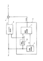
図1は、本発明の実施形態1における視覚処理装置1のブロック図である。
図1において、視覚処理装置1は、画像信号に対して所定のゲイン特性を有する第1ゲイン信号を出力するゲイン型視覚処理部70と、設定された所定の制限値で前記第1ゲイン信号を制限して第2ゲイン信号を出力するゲイン制限部5と、第2ゲイン信号に基づいて画像信号を補正する補正部9とを備えている。
また、視覚処理装置1は、第1ゲイン信号GAINを制限するための制限値Lを算出する制限値決定部4と、色飽和を検出する色飽和検出部10とを備えている。
ゲイン型視覚処理部70は、視覚処理部3と、空間処理部2とを備えている。
これにより、視覚処理装置1は、画像信号Yin、CRin、CBinに視覚処理を行い視覚処理画像Yout、CRout、CBoutを出力する。
FIG. 1 is a block diagram of a
In FIG. 1, the
The
The gain-type
Thereby, the
空間処理部2は、空間処理の対象となる対象画素の値と、対象画素の周辺領域の画素(以下、「周辺画素」という)の値とを輝度信号Yinから取得する。取得した原画像の画素ごとの輝度値Yinに空間処理を実行しアンシャープ信号USを出力する。アンシャープ信号USとは、輝度信号をローパスフィルタなどで帯域制限処理したボケ信号である。
視覚処理部3は、輝度信号Yinおよびアンシャープ信号USから2次元ゲイン関数に基づいて第1ゲイン信号GAINを求め、出力する。
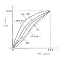
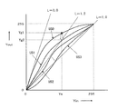
2次元ゲイン関数は、例えば、図2に示す階調変換特性と等価な入出力値を出すように階調変換曲線の傾きをゲインとする関数に設定されている。よって、輝度信号Yinの値と2次元ゲイン関数に基づいて算出された出力の値とを乗算することで、図2の示す階調変換特性と等価な入出力値を得ることができる。
The
The
For example, the two-dimensional gain function is set to a function having the gradient of the gradation conversion curve as a gain so as to obtain an input / output value equivalent to the gradation conversion characteristic shown in FIG. Therefore, by multiplying the value of the luminance signal Yin by the output value calculated based on the two-dimensional gain function, an input / output value equivalent to the gradation conversion characteristic shown in FIG. 2 can be obtained.
制限値決定部4は、第1ゲイン信号GAINを制限するための制限値Lを算出する。制限値Lによって、画像信号を補正しコントラストを制限する。例えば、明るい画像では画像の明るさを抑えて階調飽和、色飽和を防止することができる。
ゲイン制限部5は、制限値Lで第1ゲイン信号GAINを制限し、第2ゲイン信号GAIN2を出力する。第1ゲイン信号GAINを制限することで、明るさ調整を行ったときに色飽和の発生を抑えることができる。
補正部9は、乗算部6、乗算部7および乗算部8を備え、第2ゲイン信号GAIN2に応じて画像信号を補正する。
乗算部6は、第2ゲイン信号GAIN2と輝度信号Yinと乗算し、補正された輝度信号Youtを出力する。この補正された輝度信号Youtは、図2に示す階調変換特性と等価な出力である。乗算部7、乗算部8は第2ゲイン信号GAIN2と入力された色度信号CRin、CBinとを乗算し、補正された色度信号CRoutおよびCBoutを出力する。
The limit
The
The
The
つぎに、実施形態1における視覚処理装置1について、さらに詳細に説明する。
視覚処理装置1は、本発明の実施形態では、図2に示すように2次元階調変換特性を持つように設定される。ここで、図2の横軸は入力された輝度信号Yin、縦軸は変換された輝度信号Youtである。
2次元階調変換特性とは、アンシャープ信号USの値および輝度信号Yinの値を入力とし、その入力に対して出力の値を決定するための階調変換における入出力特性をいう。例えば、図2のアンシャープ信号US0、US1、US2、・・・、USnの信号レベルに応じて所定の階調変換特性を持つ。従って、輝度信号Yinの画素値を、例えば、8ビットの値とすると、256段階に分けられた輝度信号Yinの値に対する出力信号Youtの画素値が所定の2次元階調変換特性により決定される。階調変換特性は所定のガンマ特性をもつ階調変換曲線であり、アンシャープ信号の添え字について、出力が単調減少する関係にある。なお、アンシャープ信号の添え字について、出力が一部分単調減少でない箇所があったとしても、実質的に単調減少であればよい。また、図2に示すように、2次元階調変換特性において、すべての輝度信号Yinの明度値に対して、(US=US0の場合の出力値)≧(US=US1の場合の出力値)≧・・・≧(US=USnの場合の出力値)の関係を満たしている。このように、入力された画像信号の対象画素値とその周辺画素値との対比により出力信号を決定するような階調処理により、人間の目の特性に近い視覚処理を実現できる。
Next, the
In the embodiment of the present invention, the
The two-dimensional gradation conversion characteristic is an input / output characteristic in gradation conversion for inputting an unsharp signal US value and a luminance signal Yin value and determining an output value with respect to the input. For example, it has a predetermined gradation conversion characteristic according to the signal level of the unsharp signals US0, US1, US2,. Accordingly, if the pixel value of the luminance signal Yin is, for example, an 8-bit value, the pixel value of the output signal Yout with respect to the value of the luminance signal Yin divided into 256 stages is determined by a predetermined two-dimensional gradation conversion characteristic. . The gradation conversion characteristic is a gradation conversion curve having a predetermined gamma characteristic, and the output monotonously decreases with respect to the subscript of the unsharp signal. It should be noted that the subscript of the unsharp signal may be substantially monotonously reduced even if there is a portion where the output is not partly monotonously reduced. Also, as shown in FIG. 2, in the two-dimensional gradation conversion characteristics, for the brightness values of all the luminance signals Yin, (output value when US = US0) ≧ (output value when US = US1) The relationship of ≧... ≧ (output value when US = USn) is satisfied. In this way, visual processing close to the characteristics of the human eye can be realized by gradation processing that determines the output signal by comparing the target pixel value of the input image signal with its peripheral pixel values.
つぎに、視覚処理部3の説明をする。図3は、視覚処理部3の第1ゲイン信号GAINの出力を示しており、図2の階調変換曲線の傾きをゲインとした2次元ゲイン特性を持つ。ここで、図3の横軸は入力された輝度信号Yin、縦軸は第1ゲイン信号GAINの出力である。また、アンシャープ信号の添え字について、出力が単調減少する関係にある。また、図3に示すYin−Gain入出力特性において、すべての輝度信号Yinの明度値に対して、(US=US0の場合の出力GAINの値)≧(US=US1の場合の出力GAINの値)≧・・・≧(US=USnの場合の出力GAINの値)の関係を満たしている。
本発明の実施形態1の視覚処理装置1は、ゲイン信号を用いて画像信号処理を行っているが、ゲインを用いることで回路規模を削減できるという利点がある。これは、Yin−Gain入出力曲線(例えば、図3に示すYin−Gain入出力曲線)は、階調変換曲線(例えば、図2に示すYin−Yout入出力曲線)に比べて輝度信号Yinに対する曲線の変化が緩やかであるため、輝度信号Yin、アンシャープ信号USを粗く間引いても十分に処理精度を確保でき、視覚処理部3に入力する輝度信号Yinのビット精度を落とすことができるためである。特に、Yinが小さな値である場合(暗部に相当)、入出力特性を決定する曲線は、急勾配となる。例えば、図2に示すYin−Yout入出力曲線では、図2の左下部分の急勾配な曲線部分がこれに相当する。このような急勾配な曲線による入出力特性による階調変換を実現するためには、階調変換において、高分解能が必要となる。このような階調変換を実現する場合、Yin−Yout入出力曲線の急勾配な曲線部分の高分解能を実現させなければならないので、入力および出力に多くのビット数を割り当てる必要が生じる。一方、Yin−Gain入出力曲線(例えば、図3に示すYin−Gain入出力曲線)においては、Yinが小さな値である場合であっても、入出力特性において急勾配となる部分はないので、階調変換において、高分解能とする必要がない。したがって、図3に示すようなYin−Gain入出力特性変換においては、入力および出力に多くのビット数を割り当てる必要はない。これにより、ハードウェア・ロジック設計では回路規模を削減できる。
Next, the
The
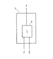
なお、視覚処理部3を輝度信号Yinおよびアンシャープ信号USと第1ゲイン信号GAINとの関係を与える2次元ルックアップテーブル(以下、「2次元LUT」という)で構成し、輝度信号Yinとアンシャープ信号USとに対して、2次元LUTを参照して第1ゲイン信号GAINを出力するようにしてもよい。これにより、2次元LUTに階調変換値を格納するよりもゲイン値を格納することで、2つの入力信号のビット数を削減でき、大幅にメモリ容量を削減できる。
また、2次元LUTで構成することで、複雑なゲイン特性も予め作成することができ、リードオンリーメモリ(以下、「ROM」という)で提供することができる。また、ゲイン特性を更新できるようにするため、書き換え可能なメモリ、例えば、ランダムアクセスメモリ(以下、「RAM」という)で構成してもよい。2次元LUTには予め設定される2次元ゲイン特性を有するゲインデータが格納されている。
The
Further, by configuring with a two-dimensional LUT, a complex gain characteristic can be created in advance, and can be provided by a read-only memory (hereinafter referred to as “ROM”). Further, in order to be able to update the gain characteristic, it may be constituted by a rewritable memory, for example, a random access memory (hereinafter referred to as “RAM”). The two-dimensional LUT stores gain data having a preset two-dimensional gain characteristic.
さらに、2次元ゲイン特性を変更することで、様々な視覚効果を得ることができる。
また、外部より2次元ゲインデータをプロファイルデータとして登録することもできる。この2次元ゲインデータを書き換えることで、視覚処理装置1は、例えば、コンピュータ、テレビ、デジタルカメラ、携帯電話、PDA、プリンタ、スキャナなどの画像を取り扱う機器において、画像信号の階調処理、ダイナミックレンジ(以下、「Dレンジ」という)の圧縮処理、ニー処理、色処理など様々な視覚効果を同じ視覚処理回路、視覚処理プログラムにより実現できるので、汎用な集積回路、汎用な視覚処理プログラムを実現できる。この2次元ゲインデータの外部からの書き換え、登録についての詳細は後述する。
つぎに、空間処理部2は、空間処理の対象となる対象画素の画素値と、対象画素の周辺画素の画素値とを輝度信号Yinから取得する。そして、空間処理部2は、取得した原画像の画素ごとの輝度値Yinに空間処理を実行しアンシャープ信号USを出力する。
Furthermore, various visual effects can be obtained by changing the two-dimensional gain characteristics.
In addition, two-dimensional gain data can be registered as profile data from the outside. By rewriting the two-dimensional gain data, the
Next, the
空間処理部2は、例えば、輝度信号Yinの対象画素に対して低域空間のみを通過させる低域空間フィルタ演算によりアンシャープ信号USを得る。フィルタ演算では、対象画素と周辺画素の画素値を、例えば、(式1)に基づいて計算する。
US=(Σ[Wij]×[Aij])/(Σ[Wij]) (式1)
ここで、[Wij]は、対象画素および周辺画素において、i行j列目に位置する画素の重み係数であり、[Aij]は、対象画素および周辺画素において、i行j列目に位置する画素の画素値である。また、「Σ」は、対象画素および周辺画素のそれぞれの画素についての合計の計算を行うことを意味している。
より具体的には、それぞれの重み係数[Wij]を1、画素値[Aij]をA(i,j)と表現して説明する。対象画素の画素値は、A(1,1)が「128」、A(0,0)が「110」、A(0,1)が「115」、A(0,2)が「117」、A(1,0)が「123」、A(1,2)が「120」、A(2,0)が「120」、A(2,1)が「127」、A(2,2)が「125」とする。このとき、3画素×3画素の領域よりアンシャープ信号USを得るには、(式1)より、US=(128+110+115+117+123+120+120+127+125)/9の演算を行う。
The
US = (Σ [Wij] × [Aij]) / (Σ [Wij]) (Formula 1)
Here, [Wij] is the weighting factor of the pixel located in the i-th row and j-th column in the target pixel and the peripheral pixels, and [Aij] is located in the i-th row and j-th column in the target pixel and the peripheral pixels. This is the pixel value of the pixel. Further, “Σ” means that the sum of the target pixel and the surrounding pixels is calculated.
More specifically, each weight coefficient [Wij] is expressed as 1, and the pixel value [Aij] is expressed as A (i, j). The pixel value of the target pixel is “128” for A (1,1), “110” for A (0,0), “115” for A (0,1), and “117” for A (0,2). , A (1,0) is "123", A (1,2) is "120", A (2,0) is "120", A (2,1) is "127", A (2,2 ) Is “125”. At this time, in order to obtain the unsharp signal US from the area of 3 pixels × 3 pixels, the calculation of US = (128 + 110 + 115 + 117 + 123 + 120 + 120 + 127 + 125) / 9 is performed from (Equation 1).
なお、画素値の差の絶対値が大きいほど小さい値の重み係数が与えられてもよいし、対象画素からの距離が大きいほど小さい重み係数が与えられてもよい。
また、周辺画素の領域は、効果に応じて、その領域の大きさが設定されるものである。周辺画素の領域は、視覚効果を得るためにはある程度大きな領域に設定することが好ましい。例えば、画像の大きさがXGA(1024×768)では、周辺画素の領域を80画素×80画素以上の大きさの領域に設定するのが好ましい。
また、低域空間フィルタとしては、アンシャープ信号USの生成に通常用いられるFIR(Finite Impulse Response)型の低域空間フィルタ、あるいはIIR(Infinite Impulse Response)型の低域空間フィルタなどを用いる。
Note that a smaller weight coefficient may be given as the absolute value of the pixel value difference is larger, or a smaller weight coefficient may be given as the distance from the target pixel is larger.
In addition, the size of the area of the peripheral pixel is set according to the effect. In order to obtain a visual effect, it is preferable to set the peripheral pixel region to a certain extent. For example, when the image size is XGA (1024 × 768), it is preferable to set the peripheral pixel region to a region having a size of 80 pixels × 80 pixels or more.
Further, as the low-pass spatial filter, a FIR (Finite Impulse Response) type low-pass spatial filter or an IIR (Infinite Impulse Response) -type low-pass spatial filter that is usually used for generating the unsharp signal US is used.
つぎに、図4、図5を用いて色飽和検出部10について説明する。図4は色飽和検出部10のブロック図である。
図4において、RGB変換部11は、輝度信号Yinと色度信号CBinおよびCRinとからRGB信号を生成する。最大値検出部12は、レッド信号(以下、「R信号」という)、グリーン信号(以下、「G信号」という)、ブルー信号(以下、「B信号」という)のうち、最大値を検出する。第1制限値算出部13は、検出されたRGB信号の最大値から制限値L1を算出する。制限値決定部4は、制限値L1、レジスタ20に設定された制限値L2、外部から入力された制限値L3からL6を参照して制限値Lを決定し、出力する。制限値決定部4の詳細は後述する。
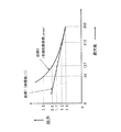
具体的には、第1制限値算出部13は、制御後のゲイン信号GAIN2の最大値が図5に示す曲線2の値以下になるように設定された曲線1に基づいて、入力された画像信号の画素ごとに制限値L1を算出する。ここで、曲線2は色飽和を起こさない制限値の最大値を示している。
Next, the color
In FIG. 4, the RGB converter 11 generates an RGB signal from the luminance signal Yin and the chromaticity signals CBin and CRin. The maximum value detector 12 detects a maximum value among a red signal (hereinafter referred to as “R signal”), a green signal (hereinafter referred to as “G signal”), and a blue signal (hereinafter referred to as “B signal”). . The first limit value calculation unit 13 calculates a limit value L1 from the detected maximum value of the RGB signal. The limit
Specifically, the first limit value calculation unit 13 inputs an image based on the
RGB信号に第1ゲイン信号GAINを乗算しても、RGB信号の各R信号、G信号、B信号の比が維持できれば色は変化しない。しかし、いずれかの信号の最大値が飽和すると、それ以上信号レベルを大きくできないため、RGB信号の比のバランスが崩れ不自然な色の変化が発生する。この色飽和を防止するためには、RGB信号の最大値に第1ゲイン信号GAINを乗算しても信号レベルの最大値を超えないようにすればよい。例えば、検出されたRGB信号の最大値が「127」のとき制限値は「2.0」となる。同様に、最大値が「84」のとき制限値は「3.0」、最大値が「212」のとき制限値は「1.2」となる。ここで、RGB信号は、「0」から「255」までの範囲をとる信号とする。よって、RGB信号の最大値をSmax、階調飽和、色飽和が抑えられる制御後の制限値Lの最大値をLmaxとすると、次のようになる。 Even if the RGB signal is multiplied by the first gain signal GAIN, the color does not change if the ratio of the R signal, the G signal, and the B signal of the RGB signal can be maintained. However, if the maximum value of any one of the signals is saturated, the signal level cannot be increased any further, and the balance of the ratio of the RGB signals is lost and an unnatural color change occurs. In order to prevent this color saturation, the maximum value of the signal level may not be exceeded even if the maximum value of the RGB signal is multiplied by the first gain signal GAIN. For example, when the maximum value of the detected RGB signal is “127”, the limit value is “2.0”. Similarly, when the maximum value is “84”, the limit value is “3.0”, and when the maximum value is “212”, the limit value is “1.2”. Here, the RGB signal is a signal having a range from “0” to “255”. Therefore, assuming that the maximum value of the RGB signal is Smax and the maximum value of the limit value L after control that can suppress gradation saturation and color saturation is Lmax, it is as follows.
Lmax=255/Smax
このように、ゲイン信号GAIN2<Lmax(曲線2)を満足する制限値L1(曲線1)を設定することで階調飽和、色飽和を抑え、色バランスを保持することができる。また、コントラストを強調した画像中に不自然な色の変化は発生しない。
なお、制限値L1の曲線1は、曲線2を折れ線近似した直線でもよいし、直線近似でもよい。RGB信号の最大値が小さい値の時はノイズを強調しない程度の値に抑えるようにすることがより好ましい。
このように、Yin信号、CBin信号、CRin信号をRGB信号に変換し、RGB信号により、最終的にディスプレイ装置等で表示される画像において、階調飽和、色飽和等が起こるか否かを判断することができる。つまり、最終的にディスプレイ装置等で表示される信号は、RGB信号であるので、予めRGB信号を取得し、RGB信号において階調飽和、色飽和等が起きるか否かを判断しておくことで、最終的にディスプレイ装置等で表示される画像の状況を予め正確に知ることができるのである。したがって、Yin信号、CBin信号、CRin信号からRGB信号を予め取得し、取得したRGB信号に基づいて、GAIN値の制限をかけるための制限値Lを決定することが効果的である。
Lmax = 255 / Smax
In this way, by setting the limit value L1 (curve 1) that satisfies the gain signal GAIN2 <Lmax (curve 2), gradation saturation and color saturation can be suppressed, and color balance can be maintained. Further, an unnatural color change does not occur in an image with enhanced contrast.
Note that the
In this way, the Yin signal, CBin signal, and CRin signal are converted into RGB signals, and the RGB signals are used to determine whether gradation saturation, color saturation, etc. occur in the image that is finally displayed on the display device or the like. can do. That is, since the signal finally displayed on the display device or the like is an RGB signal, the RGB signal is acquired in advance, and it is determined whether gradation saturation or color saturation occurs in the RGB signal. Thus, it is possible to know in advance the state of the image finally displayed on the display device or the like. Therefore, it is effective to acquire an RGB signal from the Yin signal, CBin signal, and CRin signal in advance, and to determine a limit value L for limiting the GAIN value based on the acquired RGB signal.
つぎに、図6、図7を用いて制限値決定部4の動作を説明する。制限値決定部4は制限値L1からL6を入力し、演算することで画像信号の画像の種類、画像の特徴、集積回路の自己診断に応じた制限値Lを決定するようにしてもよい。
図6において、Mレジスタ23は制限値決定部4の動作モードを決定する。例えば、図7の表24に示すようにMレジスタ23に値「2」が設定されると、制限値決定部4はレジスタ20に設定されている制限値L2の値を入力する。これにより、制限値Lは、制限値L2の固定値に設定される。視覚処理装置1において、視覚処理画像に不具合な異常が見られたときに集積回路の内部信号L1およびL3からL6をマスクし、外部より制限値L2を設定して制限値の影響を調べるなどの自己診断を行うことができる。また、内部信号L1およびL3からL6をマスクし、制限値L2に強制設定できるので、集積回路内の信号を確認するためのテスト信号に利用することもできる。
Next, the operation of the limit
In FIG. 6, the
また、Mレジスタ23に値「1」を設定すれば、制限値決定部4は、制限値L1を入力し、制限値LとしてL1を出力する。同様に、Mレジスタ23に値「3」を設定すれば、制限値決定部4は、制限値L3を入力し、制限値LとしてL3を出力する。また、Mレジスタ23に値「7」を設定すれば、制限値決定部4は、制限値L1とL3とを入力し、L1とL3とを演算して制限値Lを出力する。演算は、例えば、最小値MIN(L1,L3)を算出する演算であってもよいし、平均値Ave(L1,L3)を算出する演算であってもよい。
このように、制限値決定部4は、Mレジスタ23に設定された値に応じて、外部より入力された信号を選択して出力、あるいは演算して制限値Lを出力することができる。外部より入力される制限値L3からL6の詳細は後述する。
If the value “1” is set in the
As described above, the limit
なお、制限値決定部4が、外部より入力された信号を選択して出力する場合は、入力された制限値をそのまま制限値Lとして用いてもよく、制限値決定部4は無くてもよい。
つぎに、ゲイン制限部5は、制限値Lで第1ゲイン信号GAINを制限し、第2ゲイン信号GAIN2を出力する。
具体的には、図8に示すように、第1ゲイン信号GAINが破線で示す各制限値Lを超える場合、ゲイン出力は、すべて制限値以下に制限される。例えば、制限値L=1.2とすると、輝度信号Ysで、アンシャープ信号USがUS0である場合の出力は、L=1.2に制限されて出力される。この制限により、図9に示すように輝度信号Ysに対する出力信号Youtは、Yg1からYg2に制限される。すなわち、各制限値Lに対応する傾き以下に出力が制限されることとなる。
When the limit
Next, the
Specifically, as shown in FIG. 8, when the first gain signal GAIN exceeds each limit value L indicated by a broken line, all gain outputs are limited to the limit value or less. For example, when the limit value L = 1.2, the output when the unsharp signal US is US0 and the luminance signal Ys is limited to L = 1.2. Due to this limitation, as shown in FIG. 9, the output signal Yout for the luminance signal Ys is limited to Yg1 to Yg2. That is, the output is limited to be equal to or less than the slope corresponding to each limit value L.
つぎに、補正部9は、第2ゲイン信号GAIN2に応じて画像信号を補正する。補正部9は、乗算部6、乗算部7および乗算部8より構成される。
乗算部6は、第2ゲイン信号GAIN2と輝度信号Yinとを乗算し、輝度信号Youtを出力する。乗算部7および乗算部8は、第2ゲイン信号GAIN2と色度信号CRinおよびCBinとをそれぞれ乗算し、色度信号CRoutおよびCBoutを出力する。
なお、Yout信号、CRout信号、CBout信号は、それぞれ1つの乗算部(乗算部6〜8)により、同じゲイン値であるGAIN2を乗算されて補正部9から出力されるので、Yout信号、CBout信号、CRout信号の出力タイミングのズレは生じない。したがって、Yout信号、CBout信号、CRout信号の出力タイミングを合わせるための遅延手段等を別途設ける必要はない。
Next, the
The
Note that the Yout signal, the CRout signal, and the CBout signal are each multiplied by the same gain value GAIN2 and output from the
このようにして補正部9は画像信号を補正する。よって、明るさ調整において、補正部9は輝度レベルを大きくした部分では色度信号も大きくするので、色が薄く見えることはなくなる。また、逆に輝度レベルを小さくした部分では色度信号も小さくするので色が濃く見えることがない。さらに、第2ゲイン信号GAIN2に応じて、入力された画像信号を補正することで輝度レベルを大きくした部分での色飽和を抑えることができる。
なお、視覚処理装置1(図1)の視覚処理部3は、輝度信号Yinのみ入力し、輝度信号Yinをガンマ変換した出力と等価になるゲイン信号を出力するようにしてもよい。この構成では、視覚処理部3は、1次元のゲイン特性を有するデータを格納したLUTで構成できる。より具体的には、LUTに格納するデータとして、図3のUS0からUSnのいずれかひとつのゲイン特性を持つ変換曲線を選択してもよいし、予め設定される1次元のゲイン関数で作成してもよい。また、画像中の輝度信号のヒストグラム分布より求めた階調変換曲線と等価な出力が得られるゲイン関数でLUTに格納するデータを作成してもよい。
In this way, the
The
これにより、視覚処理部3は、ゲイン特性に基づいたデータを格納することで、ガンマ変換値をそのままテーブルデータとして格納するよりもメモリ容量を削減できる。
また、入出力する画像信号が原色信号であるRGB信号であってもよい。図10に、変形例1である視覚処理装置80のブロック図を示す。重複を避けるため、視覚処理装置1と同じ処理の説明は省略する。視覚処理装置80は、画像信号としてRGB信号を入力し、視覚処理により補正したRGB信号を出力する。
輝度色度変換部85は、入力された画像信号Rin、Gin、Binを輝度信号Yinと色度信号CRin、CBinに変換する。ここで、輝度成分の情報の抽出は人間の視感度特性に合わせてRin、Gin、Bin信号より生成する。例えば、輝度信号Yinは、次のようになる。
Thereby, the
Further, the input / output image signal may be an RGB signal which is a primary color signal. In FIG. 10, the block diagram of the
The luminance /
Yin=0.3×Rin+0.59×Gin+0.11×Bin
また、色度信号(CRin、CBin)は、次のようになる。
CRin=(−0.1687)×Rin+(−0.3313)×Gin+0.5×Bin
CBin=0.5×Rin+(−0.4187)×Gin+(−0.0813)×Bin
色飽和検出部10(図1)は、変換された輝度信号Yin、色度信号CRinおよび色度信号CBinから補正値K1を算出する。なお、色飽和検出部10のRGB変換部11(図4)は、輝度信号Yin、色度信号CBinおよび色度信号CRinからRGB信号を生成するようにしたが、入力された画像信号Rin、Gin、Binを直接利用してもよい。入力された画像信号Rin、Gin、Binを直接利用する場合は、RGB変換部11を省略することもできる。
Yin = 0.3 × Rin + 0.59 × Gin + 0.11 × Bin
The chromaticity signals (CRin, CBin) are as follows.
CRin = (− 0.1687) × Rin + (− 0.3313) × Gin + 0.5 × Bin
CBin = 0.5 × Rin + (− 0.4187) × Gin + (− 0.0813) × Bin
The color saturation detection unit 10 (FIG. 1) calculates a correction value K1 from the converted luminance signal Yin, chromaticity signal CRin, and chromaticity signal CBin. The RGB conversion unit 11 (FIG. 4) of the color
制限値決定部4(図6)は、制限値L1を参照して制限値Lを決定する。制限値決定部4は、Mレジスタ23に設定された値に応じて、外部より入力された信号を選択して制限値Lを出力、あるいは演算して制限値Lを出力する。
視覚処理部3は、空間処理部2の出力と輝度信号Yinとを入力し、第1ゲイン信号GAINを算出する。
ゲイン制限部5は、入力された第1ゲイン信号GAINを制限値Lで補正した第2ゲイン信号GAIN2を出力する。
補正部81は、乗算部82、83、84より構成され、各乗算部82、83、84は、それぞれ画像信号Rin、Gin、Binと第2ゲイン信号GAIN2とを乗算することで、視覚処理されたRGB信号であるRout、Gout、Boutを出力する。
Limit value determination unit 4 (FIG. 6) determines limit value L with reference to limit value L1. The limit
The
The
The
これにより、視覚処理装置80では、Rin、Gin、Binの比を保持したまま、コントラストなどの明るさを調整できる。また、視覚処理装置80では、制限値Lによりゲイン信号を制限できるので、コントラストなどの明るさを調整した場合であっても、階調のグラデーションの飽和、色飽和を抑えることができる。
また、視覚処理部3(図1)の出力を輝度信号Yinとの差分信号に変更してもよい。図11、図12を用いて変形例2である視覚処理装置60を説明する。
図11は、変形例2の視覚処理装置60のブロック図である。
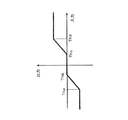
視覚処理部63は、図2に示す階調変換の出力信号と輝度信号Yinとの差分を差分信号DIFFとして出力するように構成したものである。差分信号DIFFは、図2に示す階調変換の出力信号と輝度信号Yinとの差分であり、図12に示すように、アンシャープ信号USnと輝度信号Yinに基づいて決定される差分信号となる。よって、加算部62で輝度信号Yinと差分信号DIFFを加算することで取得される信号は、図2に示す階調変換の出力信号と同じになる。
Thereby, the
Further, the output of the visual processing unit 3 (FIG. 1) may be changed to a difference signal from the luminance signal Yin. A
FIG. 11 is a block diagram of a
The
加算部62は、輝度信号Yinと差分信号DIFFを加算し、加算値Yxを算出する。この加算値Yxは、図2の階調変換後の出力信号と等価な信号である。
除算部61は、加算値Yxを輝度信号Yinの値で除算し、第1ゲイン信号GAINを算出する。すなわち、第1ゲイン信号GAINは、以下のようになる。
GAIN=Yx/Yin
この第1ゲイン信号GAINは、図2の階調変換曲線の傾きをゲインとしたものと等価である。
色飽和検出部10(図1)は、変換された輝度信号Yin、色度信号CRinおよび色度信号CBinから制限値L1を算出する。
制限値決定部4(図6)は、制限値L1を参照して制限値Lを決定する。制限値決定部4は、Mレジスタ23に設定された値に応じて、外部より入力された信号を選択して制限値Lを出力、あるいは演算して制限値Lを出力する。
The adding
The
GAIN = Yx / Yin
The first gain signal GAIN is equivalent to a gain obtained by using the gradient of the gradation conversion curve in FIG.
The color saturation detection unit 10 (FIG. 1) calculates a limit value L1 from the converted luminance signal Yin, chromaticity signal CRin, and chromaticity signal CBin.
Limit value determining unit 4 (FIG. 6) determines limit value L with reference to limit value L1. The limit
ゲイン制限部5は、入力された第1ゲイン信号GAINを制限値Lで補正した第2ゲイン信号GAIN2を出力する。
補正部9は、乗算部6、乗算部7、乗算部8により、輝度信号Yin、色度信号CRinおよび色度信号CBinと第2ゲイン信号GAIN2とをそれぞれ乗算し、輝度信号Yout、色度信号CRoutおよび色度信号CBoutを出力する。
なお、視覚処理部63は、2次元LUTで構成してもよいし、輝度信号Yinと差分信号DIFFとの関数を格納した1次元LUTでもよい。
このように階調変換曲線の出力と輝度信号Yinとの差分値をLUTに格納することで、ガンマ変換値を格納するよりもメモリ容量を削減できる。
以上のように、本発明の実施形態1によれば、入力された画像信号に対して、高性能なコントラスト調整を実施することができ、かつ、出力される画像信号の出力タイミングにズレが生じない視覚処理装置1を実現することができる。さらに、第1ゲイン信号GAINを設定された所定の制限値で制限できるようにしているため、色飽和を抑えて、明るさを調整できる。特に、高彩度色でゲイン信号を制限することができ、濃い赤色、濃い青色で色飽和を防止することができる。
The
The
The
Thus, by storing the difference value between the output of the gradation conversion curve and the luminance signal Yin in the LUT, the memory capacity can be reduced as compared with storing the gamma conversion value.
As described above, according to
また、画像信号からRGB信号に変換したときの最大値を検出する最大値検出部と、検出されたRGB信号の最大値に基づいて第1ゲイン信号を制限することで、色飽和が発生するゲイン信号のレベルを検出でき、色飽和しない制限値を算出できる。
また、視覚処理部3は、局所領域の濃淡情報であるアンシャープ信号USを用いることで画像中の暗部領域と明部領域で異なるゲイン特性で画像信号を補正できるので、画像中の暗部を明るくしても、その背景の明部領域の画像信号を飽和させることなく両方に最適なコントラスト調整ができ、色飽和を抑えられる。これにより、逆光シーン画像での暗部領域、特に、人物の顔などの肌色領域を適正な明るさに調整し、かつ、背景領域の画像信号を飽和させないようにコントラスト調整ができる。
また、視覚処理部3は、ゲイン特性に基づいた出力を行うようにした。ゲイン特性は、階調変換特性に比べて画像信号に対する特性の変化が緩やかであるため、画像信号と処理信号を粗く間引いても十分に処理精度を確保でき、信号のビット精度を落とすことができる。これにより、視覚処理部3のハードウェアの回路規模を削減でき、ルックアップテーブル構成ではメモリ容量を削減できる。
In addition, a maximum value detection unit that detects a maximum value when the image signal is converted into an RGB signal, and a gain that causes color saturation by limiting the first gain signal based on the detected maximum value of the RGB signal The signal level can be detected, and a limit value that does not cause color saturation can be calculated.
Further, the
The
また、視覚処理部3をLUTで構成することで、LUTに格納するデータを書き換えることにより異なる視覚特性を実現できる。また、複雑な非線形のゲイン特性を容易に実現できる。
また、制限値Lによりコントラストの効果を弱めることができるので、効果の強さに応じたゲイン特性データを作り直す必要がない。これにより、いろいろな強さのデータをLUTで用意しなくて済むため、メモリ容量が削減できる。また、LUT内容を入れ替える必要がないため、制限値Lをリアルタイムに変更でき、画像中の領域ごとに効果の強さを変更することができる。具体的には、フレーム単位、画素単位で制限値Lが変更できる。
(実施形態2)
つぎに、本発明の実施形態2の表示装置について、図13から図17を用いて説明する。以下、実施形態1と同様の部分については、同一符号を付し、その詳細な説明は省略する。
Further, by configuring the
In addition, since the contrast effect can be weakened by the limit value L, it is not necessary to recreate the gain characteristic data according to the strength of the effect. As a result, it is not necessary to prepare data of various strengths in the LUT, so that the memory capacity can be reduced. Further, since it is not necessary to replace the contents of the LUT, the limit value L can be changed in real time, and the strength of the effect can be changed for each region in the image. Specifically, the limit value L can be changed in frame units and pixel units.
(Embodiment 2)
Next, a display device according to a second embodiment of the present invention will be described with reference to FIGS. Hereinafter, the same parts as those in the first embodiment are denoted by the same reference numerals, and detailed description thereof is omitted.
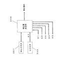
本発明の実施形態2では、視覚処理装置1の第1ゲイン信号GAINの制限値を決定する例について図13を用いて説明する。図13は、本発明の実施形態2における表示装置30の構成を示すブロック図である。
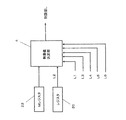
図13において、表示装置30は、番組情報を受信するチューナ31と、番組情報を分離する番組情報分離部32と、映像データと音声データを復号するAV復号部33と、映像データを視覚処理する視覚処理装置1と、処理された画像を表示する出力部35とを備える。
また、表示装置30は、映像信号の平均信号レベルを検出する信号レベル検出部34、肌色領域を検出する肌色検出部36、ジャンル情報や番組記述情報を検出する放送内容検出部37、および受信電波の電界強度を検出する電界強度検出部38の全部あるいはいずれかを備えるようにしてもよい。
In the second embodiment of the present invention, an example of determining the limit value of the first gain signal GAIN of the
In FIG. 13, a
In addition, the
チューナ31は、アンテナによって受信された受信電波から目的の放送局の電波が選択され、これが復調されて1つのトランスポートストリーム(以下、「TS」という)が復元される。
番組情報分離部32は、TSをデスクランブル処理し、映像データ、音声データ、データ放送用各種データ、EPG表示用データなどをコンテンツごとに分離する。
AV復号部33は、番組情報分離部32で分離された映像データ、音声データを映像信号、音声信号に復号化する。この映像信号は、例えば、YCbCrなどの輝度信号、色度信号である。
視覚処理装置1は、入力された映像信号を視覚処理し、出力部35に出力する。出力部35は、例えば、CRT、プラズマディスプレイパネル、液晶パネルなどのディスプレイ部と、スピーカなどの音声出力部を備え、入力された音声信号と視覚処理された映像信号とを表示する。なお、出力部35は、デバイスの表示色に合わせて入力された信号を変換して表示してもよい。例えば、輝度色度信号を原色信号であるRGB信号に変換して表示してもよい。
The
The program
The
The
なお、視覚処理装置1は、出力部35で扱える信号の構成に合わせて変形例が考えられる。例えば、輝度信号、色度信号を扱う場合は視覚処理装置1(図1)が好ましく、RGB信号を扱うには視覚処理装置80(図10)の構成が好ましい。このように映像信号に合わせた構成を用いればよい。
つぎに、視覚処理装置1の第1ゲイン信号GAINの制限値を決定する方法について、図13〜図17を用いて説明する。
図13に示す、信号レベル検出部34は、映像信号をフレームメモリに記憶し、1フレーム内または1フィールド内の映像信号の平均値を演算し平均信号レベルを検出する。この検出した平均信号レベルに応じて制限値L3を算出する。例えば、平均信号レベルが所定の値PHより高い画像を「明るい画像」と定義し、明るい画像では制限値L3を「1.0」に設定し、逆に、平均信号レベルが所定の値PLより低い画像を「暗い画像」と定義し、暗い画像では制限値L3を「2.0」に設定する。これにより、画像の特徴により制限値を設定できる。平均信号レベルは、輝度信号を平均化した平均値でもよいし、RGB信号のそれぞれの信号を平均したものを用いてもよい。また、RGB信号のそれぞれの3つの平均値をさらに平均した値でもよい。
Note that the
Next, a method for determining the limit value of the first gain signal GAIN of the
The
これにより、明るい画像でゲイン信号を制限し信号レベルを抑えることで、プラズマディスプレイパネルなどのディスプレイ装置で耐熱性を高め、消費電力を抑えることができる。
また、プラズマディスプレイパネルは、耐熱性を高め、消費電力を下げるために、表示する画像の平均輝度レベルが所定のレベルを超えると画面全体の明るさを下げるようにディスプレイパネル側で制御する表示制御機能がドライブ部に設けられている。さらに、この表示制御機能は、映像信号処理とは無関係に働く機能である。
よって、視覚処理で画像中の所定の明るさの領域を持ち上げたことにより、表示制御機能が働き、ドライブ部で画面全体の明るさを下げられてしまうと、視覚処理する前には十分明るかった領域まで暗くなり、画面全体としてめりはりのない画像となり画質が劣化する。つまり、せっかく行った視覚処理が無駄になってしまうおそれがある。そのために、視覚処理装置1において、ドライブ部の表示制御機能が働く平均信号レベル以下にゲイン信号を制限することで、効果の高いコントラスト調整ができる。
Accordingly, by limiting the gain signal and suppressing the signal level with a bright image, it is possible to improve heat resistance and suppress power consumption in a display device such as a plasma display panel.
In addition, the plasma display panel is a display control that is controlled on the display panel side to reduce the brightness of the entire screen when the average luminance level of the displayed image exceeds a predetermined level in order to increase heat resistance and reduce power consumption. Functions are provided in the drive section. Furthermore, this display control function is a function that works independently of the video signal processing.
Therefore, if the display control function is activated by raising the area of the predetermined brightness in the image by visual processing and the brightness of the entire screen can be lowered by the drive unit, it was sufficiently bright before visual processing The image is darkened to the area, and the entire screen becomes an image having no sharpness, and the image quality is deteriorated. In other words, there is a possibility that the visual processing that has been performed is wasted. For this reason, in the
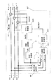
つぎに、肌色検出部36について、図14〜図16を用いて説明する。
肌色検出部36は、輝度信号Yin、色度信号CBin、色度信号CRinから肌色領域を検出し、制限値L4を算出する。図14に示すように、肌色検出部36は、色度信号CRinより所定の第1色領域を検出し重み値Kaを出力する第1色領域検出部361と、色度信号CBinより所定の第2色領域を検出し重み値Kbを出力する第2色領域検出部362と、輝度信号Yinより所定の明るさ領域を検出し重み値Kcを出力する輝度領域検出部363とを備え、肌らしさ度を各重み値の積と定義し制限値L4を求める。例えば、制限値L4は、乗算部364、365によって、制限値L4=Ka×Kb×Kcのように算出される。
ここで、肌色領域とは、図15に示すように、予め定義した色度信号の所定の範囲の領域のことである。肌色検出部36は、検出対象としている映像信号(輝度信号Yin、色度信号CBin、色度信号CRin)が肌色領域に属するか否かを検出する。例えば、色度信号CBinのCB1からCB2、色度信号CRinのCR1からCR2で囲まれる領域を肌色領域と定義する。さらに、輝度信号のYqからYpの範囲に入る画像信号の範囲を肌色領域とする。これにより、色に加え、画像の明るさに応じても制限値Lを設定できる。特に、明るい人物の顔の肌色領域では顔のテカリ、階調飽和、色飽和を抑えるように制限できるといった効果がある。
Next, the skin
The skin
Here, the skin color region is a region in a predetermined range of a predefined chromaticity signal, as shown in FIG. The skin
図16を用いて、肌色検出部36の動作を詳細に説明する。
第1色領域検出部361は色度信号CRinを入力し、図16(a)に示す重み関数によって重み値Kaを出力する。同様に、第2色領域検出部362は色度信号CBinを入力し、図16(b)に示す重み関数によって重み値Kbを出力する。輝度領域検出部363は輝度信号Yinを入力し、図16(c)に示す重み関数によって重み値Kcを出力する。肌らしさ度を各重み関数の積と定義し、制限値L4=Ka×Kb×Kcのように算出する。肌色領域と領域外との境界付近で色が不自然にならないように、対象となる肌色領域の境界は徐々に重みが変化するようにする。なお、重み関数の形状は、台形でも三角形でもよい。画像評価などにより最適な関数を設定すればよい。なお、制限値L4をKa、Kb、Kcの最小値としてもよく、平均値としてもよい。画像評価などにより最適な関数を設定すればよい。
The operation of the skin
The first color
肌色領域での各重み係数を下げ、例えば、最小値の「1.0」とすることで、肌色領域で制限値Lを抑えることができる。これにより、コントラスト調整しても、明るい画像で人物における顔の肌色のテカリを防止し、顔の濃淡を飛ばさないようにすることができる。なお、各重み係数の最小値、重み関数の形状はそれぞれ異なっていてもよい。
つぎに、放送内容検出部37について、図17を用いて説明する。
放送内容検出部37は、番組情報分離部32から分離されたEPG表示用データ、現在、受信されているデータのジャンル情報や番組記述情報を検出し、制限値L5を算出する。なお、データのジャンル情報や画像の情報は、MPEGのストリーム情報より検出してもよい。
放送内容検出部37は、例えば、図17に示すように「ニュース」「スポーツ」「ワイドショー」「映画」「ドラマ」などの受信したコンテンツの種類を検出し、それぞれ制限値L5を算出する。コンテンツの種類に応じて、例えば、コンテンツの種類が「ニュース」ならば制限値「3.0」、「スポーツ」ならば制限値「2.0」、「ワイドショー」ならば制限値「1.5」、「映画」ならば制限値「1.1」、「ドラマ」ならば制限値「1.4」を設定する。ニュース、スポーツにはめりはりをつけるため制限値を高めに設定し、ワイドショーはスタジオでの収録が多く、映像が調整されているのでほぼノーマルな設定とし、映画はシックな画像を再現するため、制限値を抑えるように設定する。このようにコンテンツに合わせて制限値を設定することで映像に最適な制限値が設定できる。制限値L5は、予めテーブル化されていてもよい。これにより、画像の種類に応じて最適な制限値L5を設定できる。なお、このテーブルを外部より変更できるようにしてもよい。
The limit value L can be suppressed in the skin color area by lowering each weight coefficient in the skin color area, for example, by setting the minimum value to “1.0”. Thereby, even if the contrast is adjusted, it is possible to prevent shining of the skin color of the face in a person with a bright image, and to avoid blurring of the face. Note that the minimum value of each weight coefficient and the shape of the weight function may be different from each other.
Next, the broadcast
The broadcast
For example, as shown in FIG. 17, the broadcast
つぎに、電界強度検出部38について説明する。
電界強度検出部38は、チューナ31で受信された受信電波の電界強度を検出し、電界強度の強弱に応じて制限値L6を算出する。例えば、電界強度が「強」の場合、制限値L6を「3.0」に設定し、電界強度が「弱」の場合、制限値L6を「1.0」に設定する。
これにより、電界強度が弱くS/Nの悪い画像のノイズが強調されないように制限値L6を設定できる。
以上のように、本発明の実施形態2によれば、信号レベル検出部34は、1フレーム、または1フィールド内の画像信号から検出した平均信号レベルに応じて制限値L3を算出でき、視覚処理装置1は、制限値L3に応じて第1ゲイン信号GAINを制限することができる。
Next, the electric field
The electric field
As a result, the limit value L6 can be set so that the noise of an image with weak electric field strength and poor S / N is not emphasized.
As described above, according to the second embodiment of the present invention, the signal
これにより、画像信号から検出した平均信号レベルに応じて制限値を設定でき、明るい画像でゲイン信号を制限し信号レベルを抑えることができる。また、信号レベルを抑えることで、プラズマディスプレイパネルなどのディスプレイ装置で耐熱性を高め、消費電力を抑えることができる。また、ディスプレイパネル側で設定されているAPL(Average Picture Level)対応機能が働くレベル以下にゲイン信号を制限することで、効果の高いコントラスト調整ができる。
また、肌色検出部36は、予め設定される色度信号に応じた重み係数Ka、Kbと輝度信号に応じた重み係数Kcの演算により肌色らしさに応じて制限値L4を算出する。視覚処理装置1は、制限値L4に応じて第1ゲイン信号GAINを制限することができる。
これにより、肌色を検出して制限値を設定できるので、明るい画像の肌色領域で制限値を下げることができ、色飽和を抑え、さらに顔のテカリを防止できる。また、明るい場面での顔の濃淡を飛ばさないようにできる。
Thereby, the limit value can be set according to the average signal level detected from the image signal, and the gain signal can be limited and the signal level can be suppressed in a bright image. In addition, by suppressing the signal level, heat resistance can be improved and power consumption can be suppressed in a display device such as a plasma display panel. In addition, by limiting the gain signal to a level below which the function corresponding to the APL (Average Picture Level) function set on the display panel side can be performed, a highly effective contrast adjustment can be performed.
The skin
As a result, the skin color can be detected and the limit value can be set, so that the limit value can be lowered in the skin color region of a bright image, color saturation can be suppressed, and face shine can be prevented. In addition, it is possible to prevent the shading of the face in a bright scene.
また、放送内容検出部37は、受信したデータから番組情報を分離する番組情報分離部32から検出した放送コンテンツに応じて制限値L5を算出する。視覚処理装置1は、制限値L5に応じて第1ゲイン信号GAINを制限することができる。
これにより、コンテンツごとに最適な制限値を設定でき、コンテンツに必要なコントラスト調整値にあわせた制限値を設定できる。
また、電界強度検出部38は、チューナ31が画像データを受信したときの電界強度値に応じて制限値L6を算出する。視覚処理装置1は、制限値L6に応じて第1ゲイン信号GAINを制限することができる。
これにより、電界強度値より制限値を設定でき、電界強度が弱く受信データのS/Nが悪い画像を検出して画像全体に対するゲイン信号を制限でき、S/Nが悪い画像のノイズの強調を抑えることができる。
The broadcast
As a result, an optimum limit value can be set for each content, and a limit value that matches the contrast adjustment value required for the content can be set.
Further, the electric field
As a result, a limit value can be set rather than the electric field strength value, an image having a weak electric field strength and a poor S / N of received data can be detected, and a gain signal for the entire image can be limited, and noise of an image having a poor S / N can be emphasized. Can be suppressed.
また、本発明の表示装置30は、通信または放送された画像データを受信するチューナ31と、画像データを映像信号に復号するAV復号部33と、復号された映像信号を視覚処理して出力する視覚処理装置1と、視覚処理された映像信号を表示する出力部35を備えている。
この構成により、画像のコントラスト調整で色飽和を抑えた視覚処理ができる表示装置30が実現できる。また、ゲイン信号を制限することで明るい画像での信号レベルを抑え、プラズマディスプレイパネルなどの表示部で耐熱性を高め、消費電力を抑えることができる。また、ディスプレイパネル側の表示制御機能が働く平均信号レベル以下にゲイン信号を制限することで、効果の高いコントラスト調整ができる。
以下、本発明の実施形態1におけるゲイン型視覚処理部70、本発明の実施形態2におけるゲイン型視覚処理部70の変形例について説明する。
In addition, the
With this configuration, it is possible to realize the
Hereinafter, modified examples of the gain-type
(実施形態3)
本発明の実施形態3として、ゲイン型視覚処理部70から出力されるゲイン信号GAINの空間周波数の帯域を制限し、入力された輝度信号Yinの値(信号レベル)がアンシャープ信号USの値(信号レベル)よりかなり大きい値(信号レベル)で変化した場合に出力信号Youtのコントラストの低下を抑える方法について図18〜図20を用いて説明する。
図18は、ゲイン型視覚処理部71の構成を示すブロック図、図19(a)はゲイン型視覚処理部71において着目画素周辺の明るさ情報を抽出する範囲を説明する説明図、図19(b)はゲイン型視覚処理部71におけるYin信号、US信号およびUSH信号の信号波形の一例を示す図、図20(a)はゲイン信号GAINを帯域制限しないときの階調変換特性を説明する説明図、図20(b)はゲイン信号GAINを帯域制限したときの階調変換特性を説明する説明図である。以下、実施形態1または実施形態2と同様の部分については、同一符号を付し、その詳細な説明は省略する。
(Embodiment 3)
As
FIG. 18 is a block diagram showing the configuration of the gain-type
図18において、ゲイン型視覚処理部71は、輝度信号Yinに対して応答可能なゲイン信号GAINの空間周波数の帯域を制限するための帯域制限部90と、帯域を制限された帯域制限信号USHから輝度信号Yinを増幅するためのゲイン信号GAINを出力するゲイン型視覚処理部70とを備えている。ここで、ゲイン型視覚処理部70において、空間処理部2は、帯域制限信号USHからアンシャープ信号USを生成し、視覚処理部3は、帯域制限信号USHとアンシャープ信号USとに基づいてゲイン信号GAINを生成する。
また、帯域制限されたゲイン信号GAINと入力された輝度信号Yinとを乗算部6により乗算することで、階調変換された輝度信号Youtを得ることができる。
これにより、輝度信号Yinに対して応答可能な空間周波数の帯域が制限されたゲイン信号GAINと輝度信号Yinとを乗算して階調変換することで、入力された輝度信号Yinの値がアンシャープ信号USよりかなり大きい値で変化した場合でも出力信号Youtのコントラストの低下を抑えるものである。このコントラストの低下の詳細については後述する。
In FIG. 18, the gain-type
In addition, the
As a result, the tone signal is unsharpened by multiplying the tone signal by multiplying the gain signal GAIN with a limited spatial frequency band that can respond to the luminance signal Yin and the luminance signal Yin, thereby converting the gradation. Even when the signal US changes to a value considerably larger than that of the signal US, the reduction in the contrast of the output signal Yout is suppressed. Details of the decrease in contrast will be described later.
帯域制限部90は、図19(a)に示すように、着目画素200の近傍の対象領域201内にある画素の値の平均値を算出するなどして入力された輝度信号Yin(例えば、図19(b)のW1の信号波形に相当)に対して応答可能な空間周波数の帯域が制限された帯域制限信号USH(例えば、図19(b)のW3の信号波形に相当)を生成する。
また、空間処理部2は、図19(a)に示すように、帯域制限信号USHの対象領域201より広範囲な対象領域202から画素の値を抽出し、着目画素200の周辺領域での明るさ情報としてアンシャープ信号US(例えば、図19(b)のW2の信号波形に相当)を生成する。例えば、対象領域202は、対象領域201の10倍から100倍程度の大きさの領域にするのが好ましい。これにより、アンシャープ信号USの空間周波数の帯域は、帯域制限信号USHの空間周波数の帯域よりかなり低い帯域に制限されたものになる。
As shown in FIG. 19A, the
Further, as illustrated in FIG. 19A, the
以下、入力された輝度信号Yinの値がアンシャープ信号USよりかなり大きい値で変化する場合に出力信号Youtのコントラスト低下を抑える方法について詳細に説明する。
まず、出力信号Youtのコントラストが低下する場合について図20(a)を用いて説明する。図20(a)は、ゲイン信号GAINを帯域制限しないときの階調変換特性を説明するための説明図である。ここで、図20(a)の横軸は入力された輝度信号Yin、縦軸は階調変換された出力信号Youtである。
図20(a)において、着目画素200の周辺の視覚処理に用いる広い対象領域202から抽出した明るさ情報であるアンシャープ信号USの値を「USa」とする。また、そのときに入力された着目画素200の近傍の対象領域201から抽出した明るさ情報の値を「USb」とする。入力された着目画素200の値Yinは、通常広い範囲の値である「USa」よりも近傍の値である「USb」に近い。
Hereinafter, a method for suppressing the decrease in contrast of the output signal Yout when the value of the input luminance signal Yin changes at a value significantly larger than the unsharp signal US will be described in detail.
First, the case where the contrast of the output signal Yout decreases will be described with reference to FIG. FIG. 20A is an explanatory diagram for explaining the gradation conversion characteristics when the gain signal GAIN is not band-limited. Here, the horizontal axis of FIG. 20A is the input luminance signal Yin, and the vertical axis is the gradation-converted output signal Yout.
In FIG. 20A, the value of the unsharp signal US, which is brightness information extracted from the
図20(a)において、視覚処理部3において、階調曲線400は、着目画素200の輝度信号Yinの値とアンシャープ信号USの値とが一致している場合の出力特性であり、着目画素200の周辺の対象領域202から抽出した明るさ情報によって選択された階調曲線により定まる曲線である。この階調曲線400により、画面全体の明るさの変化を決定している。
また、視覚処理部3において、アンシャープ信号USの値が「USa」であるとき、階調曲線205の階調曲線が選択され、アンシャープ信号US<USa(着目画素200の周囲が「USa」より暗い)のとき曲線203または曲線204が選択され、アンシャープ信号US>Usa(着目画素200の周囲が「USa」より明るい)のとき、曲線206または曲線207が選択される。
In FIG. 20A, in the
Further, in the
これにより、視覚処理部3は、アンシャープ信号USの値が「USa」であるとき、階調曲線205の階調曲線を選択し、アンシャープ信号USに変化がなければ、着目画素200の輝度信号Yinの値に対する出力信号Youtは階調曲線205にしたがって出力する。よって、視覚処理部3において、着目画素200の輝度信号Yinの値が「USa」に近いときは、階調曲線205の直線部分300での傾きに応じたゲインで階調変換されるため、出力信号Youtのコントラストは維持される。しかし、帯域制限部90を備えていない構成では、視覚処理部3において、着目画素200の近傍の明るさが「USb」で輝度信号Yinも「USb」に近い値をとる、即ち輝度信号Yinがアンシャープ信号USの値と大きく離れているとき、階調曲線205の傾きがなだらかになり、領域301での傾きに応じたゲイン信号GAINを出力する。これにより、視覚処理装置1は、このゲイン信号GAINで階調変換するため、出力信号Youtのコントラストは低下する。
Thereby, the
つぎに、この出力信号Youtのコントラスト低下を抑える方法について図20(b)を用いて説明する。図20(b)は、ゲイン信号GAINを帯域制限したときの視覚処理装置1の階調変換特性を説明するための説明図である。ここで、図20(b)の横軸は入力された輝度信号Yin、縦軸は階調変換された出力信号Youtである。
図20(b)において、着目画素200の周辺の対象領域202から抽出した明るさ情報であるアンシャープ信号USの値を「USa」とする。また、そのときに着目画素200の近傍の明るさが「USb」で輝度信号Yinも「USb」に近い値をとる。
また、視覚処理部3は、アンシャープ信号USの値が「USa」であるとき、階調曲線205の階調曲線を選択し、アンシャープ信号USに変化がなければ、輝度信号Yinの空間周波数の帯域を制限した帯域制限信号USHの値に対して出力信号Youtを決定し、階調曲線205にしたがって出力する。
Next, a method for suppressing the decrease in contrast of the output signal Yout will be described with reference to FIG. FIG. 20B is an explanatory diagram for explaining the gradation conversion characteristics of the
In FIG. 20B, the value of the unsharp signal US, which is the brightness information extracted from the
The
このとき帯域制限信号USHは、着目画素200の近傍の明るさ「USb」となる。
よって、視覚処理部3において、着目画素200の輝度信号Yinがアンシャープ信号USの値よりかなり高い「USb」前後の範囲で変化しても、細部領域では帯域制限信号USHの値は帯域制限により「USb」に固定されるため視覚処理部3が出力するゲイン信号GAINは変化しない。即ち、着目画素200近傍の細部領域では、ゲイン信号GAINはほぼ一定値(直線209の傾き)を出力する。このように、帯域制限されたゲイン信号GAINと輝度信号Yinとを乗算して階調変換することで、出力信号Youtのコントラストを維持することができる。つまり、この場合、ゲイン信号GAINがほぼ一定値であるので、出力信号Youtは、入力輝度信号Yinの信号レベルの変化にほぼ比例して出力されることになる。したがって、出力信号Youtにおいて、入力輝度信号Yinのコントラストが維持される。なお、直線209の傾きは、図20(a)の曲線205の直線部分300の傾きにより近いものであり、帯域制限信号USH<「USb」のときは直線208、帯域制限信号USH>「USb」のときは直線210となる。
At this time, the band limitation signal USH has the brightness “USb” in the vicinity of the
Therefore, in the
以上のように、本発明の実施形態3によれば、輝度信号Yinに対して応答可能な空間周波数の帯域を制限したゲイン信号GAINと輝度信号Yinを乗算して階調変換するため、入力された輝度信号Yinの値(信号レベル)がアンシャープ信号USの値(信号レベル)よりかなり大きい値(信号レベル)で変化した場合であっても、出力信号Youtのコントラストの低下を抑えることができる。
なお、輝度信号Yinに対して応答可能な空間周波数の帯域が制限されたゲイン信号GAINを生成する方法は、ゲイン型視覚処理部71の構成に限定されるものでない。
以下、ゲイン型視覚処理部71の構成における他の変形例について説明する。
まず、ゲイン型視覚処理部71の変形例を変形例3として、図21を用いて説明する。図21は、変形例3としてのゲイン型視覚処理部72の構成を示すブロック図である。
As described above, according to the third embodiment of the present invention, since the tone signal is multiplied by the gain signal GAIN and the luminance signal Yin that limit the spatial frequency band that can respond to the luminance signal Yin, the tone conversion is performed. Even when the value (signal level) of the luminance signal Yin changes to a value (signal level) that is considerably larger than the value (signal level) of the unsharp signal US, it is possible to suppress a decrease in the contrast of the output signal Yout. .
Note that the method of generating the gain signal GAIN in which the spatial frequency band that can respond to the luminance signal Yin is limited is not limited to the configuration of the gain-type
Hereinafter, another modification of the configuration of the gain-type
First, a modification of the gain-type
図21において、ゲイン型視覚処理部72は、輝度信号Yinに対して応答可能な帯域を制限した帯域制限信号USHを出力する帯域制限部90と、輝度信号Yinからアンシャープ信号USを生成する空間処理部2と、帯域制限信号USHとアンシャープ信号USとに基づいてゲイン信号GAINを生成する視覚処理部3とを備えている。
また、帯域制限されたゲイン信号GAINと輝度信号Yinとを乗算部6により乗算することで、階調変換された出力信号Youtを得ることができる。
このような構成によっても、輝度信号Yinに対して応答可能な空間周波数の帯域が制限されたゲイン信号GAINを生成でき、ゲイン型視覚処理部71と同様に、入力された輝度信号Yinの値(信号レベル)がアンシャープ信号USの値(信号レベル)よりかなり大きい値(信号レベル)で変化した場合であっても、出力信号Youtのコントラストの低下を抑えることができる。
In FIG. 21, the gain-type
Further, the
Even with such a configuration, it is possible to generate the gain signal GAIN in which the spatial frequency band that can respond to the luminance signal Yin is limited. Similarly to the gain-type
つぎに、ゲイン型視覚処理部71の変形例を変形例4として、図22を用いて説明する。図22は、変形例4としてのゲイン型視覚処理部73の構成を示すブロック図である。
図22において、ゲイン型視覚処理部73は、輝度信号Yinを入力して輝度信号Yinを増幅するためのゲイン信号GAINを出力するゲイン型視覚処理部70と、ゲイン型視覚処理部70から出力されるゲイン信号GAINの空間周波数の帯域を制限するようにした帯域制限部98とを備えている。ここで、ゲイン型視覚処理部70において、空間処理部2は、輝度信号Yinからアンシャープ信号USを生成し、視覚処理部3は、輝度信号Yinとアンシャープ信号USとに基づいてゲイン信号GAINを生成する。
帯域制限部98は、ゲイン型視覚処理部70から出力されるゲイン信号GAINに対して帯域制限を行う。
Next, a modified example of the gain-type
In FIG. 22, the gain-type
The
この帯域制限されたゲイン信号GAINと輝度信号Yinとを乗算部6により乗算することで、階調変換された出力信号Youtを得ることができる。
このような構成によっても、輝度信号Yinに対して応答可能な空間周波数の帯域が制限されたゲイン信号GAINを生成でき、ゲイン型視覚処理部71と同様に、入力された輝度信号Yinの値(信号レベル)がアンシャープ信号USの値(信号レベル)よりかなり大きい値(信号レベル)で変化した場合であっても、出力信号Youtのコントラストの低下を抑えることができる。
なお、実施形態1または実施形態2におけるゲイン型視覚処理部70をゲイン型視覚処理部71に置き換えてもよい。
また、実施形態1または実施形態2におけるゲイン型視覚処理部70をゲイン型視覚処理部72に置き換えてもよい。
By multiplying the band-limited gain signal GAIN and the luminance signal Yin by the
Even with such a configuration, it is possible to generate the gain signal GAIN in which the spatial frequency band that can respond to the luminance signal Yin is limited. Similarly to the gain-type
The gain-type
Further, the gain-type
また、実施形態1または実施形態2におけるゲイン型視覚処理部70をゲイン型視覚処理部73に置き換えてもよい。
(実施形態4)
つぎに、本発明の実施形態4として、コントラスト強調部をさらに備えた構成について図23〜図25を用いて説明する。
図23は、コントラスト強調部を備えたときの構成例を説明するための説明図、図24は階調変換特性を説明するための説明図、図25はコントラスト強調部の特性を説明するための説明図である。以下、実施形態1〜実施形態3と同様の部分については、同一符号を付し、その詳細な説明は省略する。
図23において、視覚処理装置1は、さらに、輝度信号Yinを強調した強調信号Yeを出力するコントラスト強調部91を備えている。
Further, the gain type
(Embodiment 4)
Next, as a fourth embodiment of the present invention, a configuration further including a contrast enhancement unit will be described with reference to FIGS.
FIG. 23 is an explanatory diagram for explaining a configuration example provided with a contrast emphasizing unit, FIG. 24 is an explanatory diagram for explaining gradation conversion characteristics, and FIG. 25 is a diagram for explaining characteristics of the contrast emphasizing unit. It is explanatory drawing. Hereinafter, the same parts as those in
In FIG. 23, the
以下、実施形態1におけるゲイン型視覚処理部70をゲイン型視覚処理部71に置き換えたものを実施形態4として説明する。
ゲイン型視覚処理部71において、ゲイン型視覚処理部70は、帯域制限部90により帯域を制限された帯域制限信号USHに応じて輝度信号Yinを増幅するためのゲイン信号GAINを出力する。ここで、ゲイン型視覚処理部70において、空間処理部2は帯域制限信号USHからアンシャープ信号USを生成し、視覚処理部3は帯域制限信号USHとアンシャープ信号USとに基づいてゲイン信号GAINを生成する。
コントラスト強調部91は、輝度信号Yinを強調した強調信号Yeを出力する。
このゲイン信号GAINと強調信号Yeとを乗算部6により乗算することでコントラストが強調された出力信号Youtを得ることができる。
Hereinafter, an embodiment in which the gain-type
In the gain-type
The
By multiplying the gain signal GAIN and the enhancement signal Ye by the
このように、コントラスト強調部91を備えたことで、輝度信号Yinのコントラストを強調でき、入力された輝度信号Yinの値がアンシャープ信号USよりかなり明るい場合であっても、出力信号Youtのコントラストの低下を抑えることができる。コントラスト強調部91については、後述する。
まず、出力信号Youtのコントラストが低下する場合について図24を用いて説明する。図24は、視覚処理装置1においてコントラスト変換するときの階調変換特性を説明する説明図である。ここで、図24の横軸は入力された輝度信号Yin、縦軸は階調変換された出力信号Youtである。
図24において、着目画素200の周辺の対象領域202から抽出した明るさ情報であるアンシャープ信号USの値を「USa」とする。また、そのときに入力された着目画素200の近傍の明るさが「USb」で輝度信号Yinも「USb」に近い値をとる。
Thus, by providing the
First, the case where the contrast of the output signal Yout decreases will be described with reference to FIG. FIG. 24 is an explanatory diagram for explaining gradation conversion characteristics when contrast conversion is performed in the
In FIG. 24, the value of the unsharp signal US that is the brightness information extracted from the
図24において、視覚処理部3において、階調曲線500は、着目画素200の輝度信号Yinの値とアンシャープ信号USの値とが一致している場合の出力特性であり、着目画素200の周辺の対象領域202から抽出した明るさ情報によって選択された階調曲線により定まる曲線である。この階調曲線500により、画面全体の明るさの変化を決定している。
また、視覚処理部3において、アンシャープ信号USの値が「USa」であるとき、階調曲線603の階調曲線が選択され、アンシャープ信号US<USa(着目画素200の周囲が「USa」より暗い)のとき曲線601または曲線602が選択され、アンシャープ信号US>Usa(着目画素200の周囲が「USa」より明るい)のとき、曲線604または曲線605が選択される。
In FIG. 24, in the
In the
これにより、視覚処理部3は、アンシャープ信号USの値が「USa」であるとき、階調曲線603の階調曲線を選択し、アンシャープ信号USに変化がなければ、着目画素200の輝度信号Yinの値に対する出力信号Youtは、階調曲線603にしたがって出力される。よって、視覚処理部3において、着目画素200の輝度信号Yinの値が「USa」に近いときは(図24の領域700あたりに対応。)、階調曲線603の領域700での傾きが大きくなるため、ゲイン信号の変化も大きくなり、出力信号Youtのコントラストは強調される。しかし、帯域制限部90を備えていない構成では、視覚処理部3において、着目画素200の輝度信号Yinの値が「USb」前後で、アンシャープ信号USの値よりかなり大きいときは階調曲線603の傾きがなだらかになり(図24の領域701あたりに対応。)、領域701でのゲイン信号GAINの変化も小さくなるので、出力信号Youtのコントラストは低下する。
Thereby, the
つぎに、領域701での出力信号Youtのコントラスト低下を抑える方法について図25を用いて説明する。図25は、コントラスト強調部91の特性を説明する説明図である。ここで、図25の横軸は入力された輝度信号Yin、縦軸は階調変換された出力信号Youtである。
図25において、着目画素200の周辺の対象領域202から抽出した明るさ情報であるアンシャープ信号USの値を「USa」とする。また、そのときに着目画素200近傍の明るさが「USb」で輝度信号Yinも「USb」に近い値をとる。
また、視覚処理部3は、アンシャープ信号USの値が「USa」であるとき、階調曲線603の階調曲線を選択し、アンシャープ信号USに変化がなければ、輝度信号Yinの空間周波数の帯域を制限した帯域制限信号USHの値に対して出力信号Youtを決定し、階調曲線603にしたがって出力する。階調曲線603は、値「USa」の近傍において傾きが大きいため、ゲイン信号GAINの変化も大きくなり、コントラストを強調することができる。
Next, a method for suppressing a decrease in contrast of the output signal Yout in the
In FIG. 25, the value of the unsharp signal US, which is the brightness information extracted from the
The
一方、帯域制限信号USHは、着目画素200の近傍の明るさ「USb」になる。
よって、視覚処理部3において、着目画素200の輝度信号Yinがアンシャープ信号USの値よりかなり高い「USb」前後の範囲で変化しても、細部領域では帯域制限信号USHの値は帯域制限により「USb」に固定されるため視覚処理部3が出力するゲイン信号GAINは変化しない。即ち、着目画素200近傍の細部領域では、ゲイン信号GAINはほぼ一定値(曲線603の直線部分近傍の傾き)を出力する。この場合、ゲイン信号GAINがほぼ一定値であるので、出力信号Youtは、コントラスト強調部91の出力Yeの信号レベルの変化にほぼ比例して出力されることになる。そして、輝度信号Yinをコントラスト強調部91でコントラストを強調した信号Yeと帯域制限されたゲイン信号GAINとを乗算して階調変換すれば、出力信号Youtのコントラストを高めることができる。
On the other hand, the band limitation signal USH has the brightness “USb” in the vicinity of the
Therefore, in the
つぎに、コントラスト強調部91について説明する。コントラスト強調部91は、輝度信号Yinと帯域制限信号USHとの比に基づいた(式2)のように強調信号Yeを生成する。ここで、αは強調度合いを調節するパラメータである。
Ye=Yinα/(USH)α−1 (式2)
これにより、図25に示すように、帯域制限信号USH=USbのとき、曲線802にしたがって輝度信号Yinの値を強調することができる。また、帯域制限信号USH<「USb」のときは曲線801、帯域制限信号USH>「USb」のときは曲線803にそれぞれ従って輝度信号Yinの値を強調することができる。
(式2)は、αを1以上(例えば1.5)にとると、着目画素200の値と帯域制限信号USHとの比を拡大する働きをするため、コントラストは強調される。
Next, the
Ye = Yin α / (USH) α-1 (Formula 2)
As a result, as shown in FIG. 25, the value of the luminance signal Yin can be enhanced according to the
In (Expression 2), when α is set to 1 or more (for example, 1.5), the ratio of the value of the
なお、コントラスト強調部91は、輝度信号Yinと帯域制限信号USHとの差に基づいた(式3)ように強調信号Yeを生成するようにしてもよい。
Ye=Yin+(α−1)×(Yin−USH) (式3)
(式3)も、αを1以上(例えば1.5)にとると、着目画素200の値と帯域制限信号USHとの差を拡大するよう作用するため、コントラストは強調される。
コントラスト強調部91は、図26に示すように、輝度信号Yinと帯域制限信号USHとを入力する2次元LUTを備えてもよい。LUT94には、(式2)または(式3)による演算結果を予め求めたデータを設定する。
以上のように、本発明の実施形態4によれば、コントラスト強調部91を備えたことにより、輝度信号Yinのコントラストを強調し、入力された輝度信号Yinの値(信号レベル)がアンシャープ信号USの値(信号レベル)よりかなり大きい値(信号レベル)で変化した場合であっても、出力信号Youtのコントラストの低下を抑えることができる。
The
Ye = Yin + (α−1) × (Yin−USH) (Formula 3)
(Equation 3) also acts to increase the difference between the value of the pixel of
As shown in FIG. 26, the
As described above, according to the fourth embodiment of the present invention, the
なお、コントラスト強調部91の変形例を変形例5として図27に示す。図27は、変形例5としてのコントラスト強調部92の構成を示すブロック図である。
図27において、コントラスト強調部92は、(式2)の演算をLUT95とLUT96および乗算部900とによって実現している。ここで、LUT95にはYinαの演算結果を設定し、LUT96には(USH)1−αの演算結果を設定する。
また、コントラスト強調部91の変形例を変形例6として図28に示す。図28は変形例6としてのコントラスト強調部93の構成を示すブロック図である。
図28において、コントラスト強調部93は、(式3)の演算を加算部901と加算部902およびLUT97とによって実現している。ここで、LUT97には、図25に示すような出力特性のデータを設定する。ここで、図29の横軸はLUT97の入力、縦軸はLUT97の出力である。
Note that a modified example of the
In FIG. 27, the
A modification of the
In FIG. 28, the
図29に示すように、LUT97において、入力がThbからThcまでは出力を「0」とし、ノイズの強調を抑えている。また、LUT97において、入力がThaからThbまで徐々に出力を増加させ、同様に、入力がThcからThdまで徐々に出力を増加させるようにしている。また、コントラストを強調しすぎないように、入力がThaまたはThdのところまでは出力を増加させ、それ以上に輝度信号Yinと帯域制限信号USHとの差があるときは出力を飽和させるようにしている。なお、LUT97に変えて、乗算器を備え、加算部902の出力を(α−1)倍にするようにしてもよい。
なお、コントラスト強調部91に入力する帯域制限信号USHは、ゲイン型視覚処理部71の帯域制限部90の出力としたが、この構成に限定されるものでない。
構成の変形例を変形例7として、図30に示す構成において、ゲイン型視覚処理部72の帯域制限部90の出力を使用する構成としてもよい。
As shown in FIG. 29, in the
The band limiting signal USH input to the
As a modification example 7 of the configuration, the output of the
また、構成の変形例を変形例8として、図31に示す構成において、ゲイン型視覚処理部73と独立に設けた帯域制限部90の帯域制限信号USHを使用する構成としてもよい。
以上のように、本発明の実施形態1から本発明の実施形態4によれば、色飽和を抑え、画像のコントラストを調整可能とする視覚処理装置、表示装置、撮影装置、携帯情報装置および集積回路を提供できる。
なお、図32に示すように、ゲイン型視覚処理部74は、輝度信号Yinを階調変換した出力信号Youtを出力する階調型視覚処理部75を用いることによっても実現できる。
階調型視覚処理部75を用いる場合は、階調型視覚処理部75と、階調型視覚処理部75の出力を輝度信号Yinで除算する除算部61とを備えることでゲイン型視覚処理部74が実現できる。
Further, as a
As described above, according to the first to fourth embodiments of the present invention, the visual processing device, the display device, the photographing device, the portable information device, and the integration capable of suppressing the color saturation and adjusting the contrast of the image. A circuit can be provided.
As shown in FIG. 32, the gain-type
When the gradation type
階調型視覚処理部75は、輝度信号Yinからアンシャープ信号USを出力する空間処理部2と、輝度信号Yinとアンシャープ信号USとに応じて階調変換し、出力信号Youtを出力する視覚処理部64とを備えている。視覚処理部64は、例えば図2に示すような2次元階調変換特性にもとづいて出力信号Youtを出力する。これにより、ゲイン型視覚処理部74は、本発明の実施形態1のゲイン型視覚処理部70と等価な特性となり、置き換えて使用することができる。
(実施形態5)
つぎに、実施形態5である視覚処理装置について説明する。
図33は、本発明の実施形態5における視覚処理装置1’のブロック図である。視覚処理装置1’は画像信号Yin、CRin、CBinに視覚処理を行い視覚処理画像Yout、CRout、CBoutを出力する。
The gradation-type
(Embodiment 5)
Next, a visual processing device according to
FIG. 33 is a block diagram of a
空間処理部2は、空間処理の対象となる対象画素と、対象画素の周辺領域の画素(周辺画素)との画素値を輝度信号Yinから取得する。取得した原画像の画素ごとの輝度値Yinに空間処理を実行しアンシャープ信号USを出力する。アンシャープ信号USは輝度信号をローパスフィルタで処理したボケ信号である。
視覚処理部3は、輝度信号Yinおよびアンシャープ信号USから2次元ゲイン関数に基づいて第1ゲイン信号GAINを求め、出力する。
2次元ゲイン関数は、例えば、図2の示す階調変換特性の傾きをゲインとする関数に設定される。よって、輝度信号Yinと2次元ゲイン関数に基づいて算出された出力を乗算することで、図2の示す階調変換特性と等価な入出力特性を出すことができる。
補正値決定部334は第1ゲイン信号GAINを補正するための補正値Kを算出する。補正値Kによって、画像信号を補正しコントラストの強調または抑制を行う。例えば、暗い画像では画像を明るく強調でき、明るい画像では画像の明るさを抑えて階調飽和、色飽和を抑えることができる。
The
The
For example, the two-dimensional gain function is set to a function having the gradient of the gradation conversion characteristic shown in FIG. 2 as a gain. Therefore, by multiplying the luminance signal Yin and the output calculated based on the two-dimensional gain function, input / output characteristics equivalent to the gradation conversion characteristics shown in FIG. 2 can be obtained.
The correction
ゲイン制御部335は、補正値Kで第1ゲイン信号GAINを画素単位で補正し、第2ゲイン信号GAIN2を出力する。第1ゲイン信号GAINを補正値Kで補正することで、第1ゲイン信号GAINを変更せずに、コントラストの強調または抑制するための第2ゲイン信号GAIN2を生成できる。
補正部9は、乗算部6、乗算部7および乗算部8より構成され、第2ゲイン信号GAIN2に応じて画像信号を補正する。補正により画像信号のコントラストの強調または抑制を行う。
乗算部6は、第2ゲイン信号GAIN2と輝度信号Yinとを乗算し、補正された輝度信号Youtを出力する。この補正された輝度信号Youtは、図2に示す階調変換特性と等価な出力である。乗算部7、乗算部8は、第2ゲイン信号GAIN2と入力された色度信号CRin、色度信号CBinとを乗算し、補正された色度信号CRoutおよび色度信号CBoutを出力する。
The
The
The
次に、本実施形態における視覚処理装置1’について、さらに詳しく説明する。
視覚処理装置1’は、本実施形態においては図2に示すように2次元階調変換特性を持つように設定される。ここで、横軸は入力された輝度信号Yin、縦軸は変換された輝度信号Youtである。
視覚処理部3については、実施形態1で説明したものと同じであるので、ここでは説明を省略する。
本発明の実施形態5の視覚処理装置1’は、ゲイン信号を用いて画像信号処理を行っているが、ゲインを用いることで回路規模を削減できるという利点がある。これについても実施形態で説明したので、ここでは説明を省略する。
空間処理部2についても、実施形態1で説明したものと同じであるので、ここでは説明を省略する。
Next, the
In this embodiment, the
Since the
The
Since the
次に、図34、図35を用いて色飽和検出部331について説明する。図34は色飽和検出部331のブロック図である。
図34において、RGB変換部11は、輝度信号Yinと色度信号CRin、色度信号CBinからRGB信号を生成する。最大値検出部12は、R信号、G信号、B信号のうち、最大値を検出する。第1補正値算出部341は、検出されたRGB信号の最大値から補正値K1を算出する。補正値決定部334は、補正値K1、レジスタ342に設定された補正値K2、外部から入力された補正値K3からK6を参照して補正値Kを決定し、出力する。補正値決定部334の詳細は後述する。
具体的には、第1補正値算出部341は、制御後のゲイン信号GAIN2の最大値が図35に示す曲線2の値以下になるように設定された曲線1に基づいて、入力された画像信号の画素ごとに補正値K1を算出する。ここで、曲線2は色飽和を起こさない補正値の最大値を示している。
Next, the color
In FIG. 34, the RGB converter 11 generates an RGB signal from the luminance signal Yin, the chromaticity signal CRin, and the chromaticity signal CBin. The maximum value detector 12 detects the maximum value among the R signal, G signal, and B signal. The first correction
Specifically, the first correction
RGB信号に第1ゲイン信号GAINを乗算しても、RGB信号の各R信号、G信号、B信号の比が維持できれば色は変化しない。しかし、いずれかの信号の最大値が飽和すると、それ以上信号レベルを大きくできないため、RGB信号の比のバランスが崩れ不自然な色の変化が生じてしまう。この色飽和を防止するためには、RGB信号の最大値に第1ゲイン信号GAINを乗算しても信号レベルの最大値を超えないようにすればよい。例えば、検出されたRGB信号の最大値が「127」のときゲイン制御後の最大値は「2.0」となる。同様に、最大値が「84」のときゲイン制御後の最大値は「3.0」、最大値が「212」のときゲイン制御後の最大値は「1.2」となる。ここで、RGB信号は、「0」から「255」までの範囲をとる信号とする。よって、RGB信号の最大値をSmax、階調飽和、色飽和が抑えられる制御後のゲイン信号GAIN2の最大値をKmaxとすると、Kmax=255/Smaxとなる。 Even if the RGB signal is multiplied by the first gain signal GAIN, the color does not change if the ratio of the R signal, the G signal, and the B signal of the RGB signal can be maintained. However, when the maximum value of any one of the signals is saturated, the signal level cannot be increased any more, and the balance of the ratio of the RGB signals is lost, resulting in an unnatural color change. In order to prevent this color saturation, the maximum value of the signal level may not be exceeded even if the maximum value of the RGB signal is multiplied by the first gain signal GAIN. For example, when the maximum value of the detected RGB signal is “127”, the maximum value after gain control is “2.0”. Similarly, when the maximum value is “84”, the maximum value after gain control is “3.0”, and when the maximum value is “212”, the maximum value after gain control is “1.2”. Here, the RGB signal is a signal having a range from “0” to “255”. Therefore, assuming that the maximum value of the RGB signal is Smax and the maximum value of the gain signal GAIN2 after the control that suppresses gradation saturation and color saturation is Kmax, Kmax = 255 / Smax.
このように、ゲイン信号GAIN2<Kmax(曲線2)を満足する補正値K1(曲線1)を設定することで階調飽和、色飽和が抑え、色バランスを保持することができる。また、コントラストを強調した画像中に不自然な色の変化は発生しない。補正値Kによるゲイン制御の方法の詳細については後述する。
なお、補正値K1の曲線1は、曲線2を折れ線近似した直線でもよいし、直線近似でもよい。RGB信号の最大値が小さい値のときはノイズを強調しない程度の値に抑えるようにすることがより好ましい。
このように、Yin信号、CBin信号、CRin信号をRGB信号に変換し、RGB信号により、最終的にディスプレイ装置等で表示される画像において、階調飽和、色飽和等が起こるか否かを判断することができる。つまり、最終的にディスプレイ装置等で表示される信号は、RGB信号であるので、予めRGB信号を取得し、RGB信号において階調飽和、色飽和等が起きるか否かを判断しておくことで、最終的にディスプレイ装置等で表示される画像の状況を予め正確に知ることができるのである。したがって、Yin信号、CBin信号、CRin信号からRGB信号を予め取得し、取得したRGB信号に基づいて算出された補正値Kによりゲイン制御を行うことが効果的である。
In this way, by setting the correction value K1 (curve 1) that satisfies the gain signal GAIN2 <Kmax (curve 2), gradation saturation and color saturation can be suppressed, and color balance can be maintained. Further, an unnatural color change does not occur in an image with enhanced contrast. Details of the gain control method using the correction value K will be described later.
The
In this way, the Yin signal, CBin signal, and CRin signal are converted into RGB signals, and the RGB signals are used to determine whether gradation saturation, color saturation, etc. occur in the image that is finally displayed on the display device or the like. can do. That is, since the signal finally displayed on the display device or the like is an RGB signal, the RGB signal is acquired in advance, and it is determined whether gradation saturation or color saturation occurs in the RGB signal. Thus, it is possible to know in advance the state of the image finally displayed on the display device or the like. Therefore, it is effective to acquire an RGB signal from the Yin signal, CBin signal, and CRin signal in advance, and to perform gain control using the correction value K calculated based on the acquired RGB signal.
次に、図36、図37を用いて補正値決定部334の動作を説明する。補正値決定部334は、補正値K1からK6を入力し、演算することで画像信号の画像の種類、画像の特徴、集積回路の自己診断に応じた補正値Kを決定するようにしてもよい。
図36において、Mレジスタ23は補正値決定部334の動作モードを決定する。例えば、図37の表371に示すようにMレジスタ23に値「2」が設定されると、補正値決定部334は、レジスタ342に設定される補正値K2の値を入力する。これにより、補正値Kは、補正値K2の固定値に設定され、視覚処理画像に不具合な異常が見られたときに集積回路の内部信号K1およびK3からK6をマスクし、外部より補正値K2を設定して補正値の影響を調べるなどの自己診断を行うことができる。また、内部信号K1およびK3からK6をマスクし、補正値K2に強制設定できるので、集積回路内の信号を確認するためのテスト信号に利用することもできる。
Next, the operation of the correction
In FIG. 36, the
また、Mレジスタ23に値「1」を設定すれば、補正値決定部334は、補正値K1を入力し、補正値KとしてK1を出力する。同様に、Mレジスタ23に値「3」を設定すれば、補正値決定部334は、補正値K3を入力し、補正値KとしてK3を出力する。また、Mレジスタ23に値「7」を設定すれば、補正値決定部334は、補正値K1とK3とを入力し、K1とK3とを演算して補正値Kを出力する。演算は、例えば、最小値MIN(K1,K3)を算出する演算であってもとしてもよいし、平均値Ave(K1,K3)を算出する演算であってもよい。
このように、補正値決定部334は、Mレジスタ23に設定された値に応じて、外部より入力された信号を選択して出力、あるいは演算して補正値Kを出力することができる。外部より入力される補正値K3からK6の詳細は後述する。
If the value “1” is set in the
As described above, the correction
なお、補正値決定部334が、外部より入力された信号を選択して出力する場合は、入力された補正値をそのまま補正値Kとして用いてもよく、補正値決定部334は無くてもよい。
次に、ゲイン制御部335は、補正値Kで第1ゲイン信号GAINを補正し、第2ゲイン信号GAIN2を出力する。
より具体的に、設定される補正値Kによる制御方法について説明する。
まず、例えば、図38に示すように補正値Kでゲイン1倍とゲイン信号GAINとを内分または外分して制御する方法(以下、「内分・外分制御」と記す)がある。ここで、ゲイン信号GAIN2はGAIN2=補正値K×ゲイン信号GAIN+(1−補正値K)×1となる内分・外分演算を実施する。ここで、ゲイン信号を制御する演算は、K>1なら外分演算になりゲインを強調し、K=1で1倍、0<K<1で内分演算になりゲインを抑制する。また、式を変形してGAIN2=補正値K×(ゲイン信号GAIN−1)+1としてもよい。いずれも、補正値Kで1倍とゲイン信号GAINの差を拡大または縮小するように補正する。
When the correction
Next, the
More specifically, a control method using the set correction value K will be described.
First, for example, as shown in FIG. 38, there is a method of controlling by dividing the
なお、GAIN2<Kmaxとなるように補正値Kを設定すれば、色飽和を抑えることができる。画質的には、K>1ならコントラストが強くなり強調され、0<K<1でコントラストが弱く抑制される。色飽和を抑えるには、コントラストを抑制するように0<K<1とすればよい。
また、補正値の制御方法として図39に示すように補正値K(Koffset)を加算して制御する方法でもよい。ここで、ゲイン信号GAIN2はGAIN2=補正値K+ゲイン信号GAINとなる。さらに、色飽和を抑えるには、GAIN2<Kmaxとなるように補正値Kを設定する。
よって、K>0ならゲインを強調する制御となり、K=0なら補正なし、K<0ならゲインを抑えるように制御される。画質的には、K>0ならコントラストが強くなり強調され、K<0でコントラストが弱くなり抑制される。色飽和を抑えるには、K<0としコントラストを抑制する。
If the correction value K is set so that GAIN2 <Kmax, color saturation can be suppressed. In terms of image quality, if K> 1, the contrast becomes strong and emphasized, and 0 <K <1 suppresses the contrast weakly. In order to suppress color saturation, 0 <K <1 may be set so as to suppress contrast.
Further, as a control method of the correction value, a method of adding and controlling the correction value K (Koffset) as shown in FIG. 39 may be used. Here, the gain signal GAIN2 is GAIN2 = correction value K + gain signal GAIN. Further, in order to suppress color saturation, the correction value K is set so that GAIN2 <Kmax.
Therefore, if K> 0, the gain is controlled to be emphasized, if K = 0, no correction is performed, and if K <0, the gain is controlled. In terms of image quality, if K> 0, the contrast becomes strong and emphasized, and if K <0, the contrast becomes weak and suppressed. To suppress color saturation, K <0 and contrast is suppressed.
なお、乗算値により増幅・減衰を制御する方法では、GAIN2=補正値K×ゲイン信号GAINとなる。さらに、色飽和を抑えるには、GAIN2<Kmaxとなるように補正値Kを設定するようにしてもよい。
このように、ゲイン制御部335は、補正値Kで第1ゲイン信号GAINを補正し、第2ゲイン信号GAIN2を出力することで、画像全体のコントラストを強調することも抑制することもできる。
次に、補正部9は、第2ゲイン信号GAIN2に応じて画像信号を補正する。補正部9は、乗算部6、乗算部7および乗算部8より構成される。
乗算部6は、第2ゲイン信号GAIN2に輝度信号Yinを乗算して輝度信号Youtを出力する。乗算部7および乗算部8は第2ゲイン信号GAIN2に色度信号CRinおよび色度信号CBinを乗算し、色度信号CRoutおよびCBoutを出力する。
In the method of controlling amplification / attenuation by the multiplication value, GAIN2 = correction value K × gain signal GAIN. Furthermore, in order to suppress color saturation, the correction value K may be set so that GAIN2 <Kmax.
As described above, the
Next, the
The
なお、Yout信号、CRout信号、CBout信号は、それぞれ1つの乗算部(乗算部6〜8)により、同じゲイン値であるGAIN2を乗算されて補正部9から出力されるので、Yout信号、CBout信号、CRout信号の出力タイミングのズレは生じない。したがって、Yout信号、CBout信号、CRout信号の出力タイミングを合わせるための遅延手段等を別途設ける必要はない。
このように補正部9は画像信号を補正する。よって、明るさ調整において、補正部9は輝度レベルを大きくした部分では色度信号も大きくするので、色が薄く見えることはなくなる。また、逆に輝度レベルを小さくした部分では色度信号も小さくするので色が濃く見えることがない。さらに、第2ゲイン信号GAIN2に応じて、入力された画像信号を補正することで輝度レベルを大きくした部分での色飽和を抑えることができる。また、補正値により第2ゲイン信号GAIN2を制御し、逆光画像などの人物の暗くなった顔領域のみを強調するように明るく補正することもできる。
Note that the Yout signal, the CRout signal, and the CBout signal are each multiplied by the same gain value GAIN2 and output from the
In this way, the
なお、視覚処理装置1’(図33)の視覚処理部3は、輝度信号Yinのみ入力し、輝度信号Yinをガンマ変換した出力と等価になるゲイン信号を出力するようにしてもよい。この構成では、視覚処理部3は、1次元のゲイン特性を有するデータを格納したLUTで構成できる。より具体的には、LUTに格納するデータとして、図3のUS0からUSnのいずれか1つのゲイン特性を持つ変換曲線を選択してもよいし、予め設定される1次元のゲイン関数で作成してもよい。また、画像中の輝度信号のヒストグラム分布より求めた階調変換曲線と等価な出力が得られるゲイン関数でLUTに格納するデータを作成してもよい。
これにより、視覚処理部3は、ゲイン特性に基づいたデータを格納することで、ガンマ変換値をそのままテーブルデータとして格納するよりもメモリ容量を削減できる。
Note that the
Thereby, the
また、入出力される画像信号が原色信号であるRGB信号であってもよい。図40に、変形例1である視覚処理装置80’のブロック図を示す。重複を避けるため、視覚処理装置1と同じ処理の説明は省略する。視覚処理装置80’は、画像信号としてRGB信号を入力し、視覚処理により補正したRGB信号を出力する。
輝度色度変換部85は、入力された画像信号Rin、Gin、Binを輝度信号Yinと色度信号CRin、色度信号CBinに変換する。ここで、輝度成分の情報の抽出は人間の視感度特性に合わせてRin、Gin、Bin信号より生成する。例えば、輝度信号Yinは、Yin=0.299×Rin+0.587×Gin+0.114×Binとする。また、色度信号(CRin、CBin)は、CRin=(−0.1687)×Rin+(−0.3313)×Gin+0.5×Bin、CBin=0.5×Rin+(−0.4187)×Gin+(−0.0813)×Binである。
The input / output image signal may be an RGB signal that is a primary color signal. FIG. 40 is a block diagram of a
The luminance /
色飽和検出部331(図33)は、変換された輝度信号Yin、色度信号CRinおよび色度信号CBinから補正値K1を算出する。なお、色飽和検出部331のRGB変換部11(図34)は、輝度信号Yin、色度信号CBinおよび色度信号CRinからRGB信号を生成するようにしたが、入力された画像信号Rin、Gin、Binを直接利用してもよい。この場合、RGB変換部11はなくてもよい。
補正値決定部334(図36)は、補正値K1を参照し、補正値Kを決定する。補正値Kは、Mレジスタ23に設定された値に応じて、外部より入力された信号を選択して出力、あるいは演算して補正値Kを出力する。
視覚処理部3は、空間処理部2の出力と輝度信号Yinとを入力し、第1ゲイン信号GAINを算出する。
The color saturation detection unit 331 (FIG. 33) calculates a correction value K1 from the converted luminance signal Yin, chromaticity signal CRin, and chromaticity signal CBin. The RGB conversion unit 11 (FIG. 34) of the color
The correction value determination unit 334 (FIG. 36) refers to the correction value K1 and determines the correction value K. The correction value K selects and outputs a signal input from the outside according to the value set in the
The
ゲイン制御部335は、入力された第1ゲイン信号GAINを補正値Kで補正した第2ゲイン信号GAIN2を出力する。
補正部81は、乗算部82、83、84より構成され、各乗算部82、83、84はそれぞれ画像信号Rin、Gin、Binと第2ゲイン信号GAIN2とを乗算することで、視覚処理されたRGB信号であるRout、Gout、Boutを出力する。これにより、Rin、Gin、Binの比を保持したまま、コントラストを強調または抑制できる。また、補正値Kによりゲイン信号を強調または抑制するように制御できるので、階調のグラデーションの飽和、色飽和を抑えるように抑制できる。また、逆光シーンでの人物の顔の肌色のコントラストを強調するようにできる。
また、視覚処理部3(図33)の出力を、階調変換後の出力信号と輝度信号Yinとの差分信号に変更してもよい。図41、図42を用いて変形例2である視覚処理装置60を説明する。
The
The
Further, the output of the visual processing unit 3 (FIG. 33) may be changed to a difference signal between the output signal after gradation conversion and the luminance signal Yin. A
図41は変形例2の視覚処理装置60’のブロック図である。視覚処理部63は、図2に示す階調変換の出力信号と輝度信号Yinとの差分を差分信号DIFFとして出力するように構成したものである。差分信号DIFFは、図2に示す階調変換の出力信号と輝度信号Yinとの差分であり、図42に示すように、アンシャープ信号USnと輝度信号Yinとに基づいて決定される差分信号となる。よって、加算部62で輝度信号Yinと差分信号DIFFとを加算することで取得される信号は、図2に示す階調変換の出力信号と同じになる。
加算部62は、輝度信号Yinと差分信号DIFFを加算し、加算値Yxを算出する。この加算値Yxは、図2の階調変換後の出力信号と等価な信号である。
除算部61は、加算値Yxを輝度信号Yinの値で除算し、第1ゲイン信号GAINを算出する。すなわち、GAIN=Yx/Yinとなる。この第1ゲイン信号GAINは、図2の階調変換曲線の傾きをゲインとしたものと等価である。
FIG. 41 is a block diagram of a
The adding
The
色飽和検出部331(図33)は、変換された輝度信号Yin、色度信号CRinおよび色度信号CBinから補正値K1を算出する。
補正値決定部334(図36)は、補正値K1を参照し、補正値Kを決定する。補正値Kは、Mレジスタ23に設定された値に応じて、外部より入力された信号を選択して出力、あるいは演算して補正値Kを出力する。
ゲイン制御部335は、入力された第1ゲイン信号GAINを補正値Kで補正した第2ゲイン信号GAIN2を出力する。
補正部9は、乗算部6、7、8で輝度信号Yin、色度信号CRin、色度信号CBinに、それぞれ第2ゲイン信号GAIN2を乗算し、輝度信号Yout、色度信号CRout、色度信号CBoutを出力する。
The color saturation detection unit 331 (FIG. 33) calculates a correction value K1 from the converted luminance signal Yin, chromaticity signal CRin, and chromaticity signal CBin.
The correction value determination unit 334 (FIG. 36) refers to the correction value K1 and determines the correction value K. The correction value K selects and outputs a signal input from the outside according to the value set in the
The
The
なお、視覚処理部63は、2次元LUTで構成してもよいし、輝度信号Yinと差分信号DIFFとの関数を格納した1次元LUTでもよい。
このように階調変換曲線の出力と輝度信号Yinとの差分値をLUTに格納することで、階調変換曲線のガンマ変換値を格納するよりもメモリ容量を削減できる。
以上のように本実施形態によれば、入力された画像信号に対して、高性能なコントラスト調整を実施することができ、かつ、出力される画像信号の出力タイミングにズレが生じない視覚処理装置1を実現することができる。さらに、第1ゲイン信号GAINを設定された所定の補正値Kでゲイン信号を補正することで画像全体のコントラストを強調することも抑制することもできる。補正値Kでゲインを大きくすることで、逆光シーン画像での暗部にある人物の顔領域などを強調でき、レフ板効果を持たせることができる。また、補正値Kでゲインを小さくすることで、濃い赤色、濃い青色で色飽和、階調飽和を抑えることができる。
The
Thus, storing the difference value between the output of the gradation conversion curve and the luminance signal Yin in the LUT can reduce the memory capacity compared to storing the gamma conversion value of the gradation conversion curve.
As described above, according to the present embodiment, a visual processing device that can perform high-performance contrast adjustment on an input image signal and does not cause a deviation in the output timing of the output image signal. 1 can be realized. Further, the contrast of the entire image can be enhanced or suppressed by correcting the gain signal with the predetermined correction value K set for the first gain signal GAIN. By increasing the gain with the correction value K, it is possible to enhance the face area of the person in the dark part of the backlight scene image, and to have a reflex board effect. Further, by reducing the gain with the correction value K, it is possible to suppress color saturation and gradation saturation with dark red and dark blue.
また、画像信号からRGB信号に変換したときの最大値を検出する最大値検出部と、検出されたRGB信号の最大値に基づいて第1ゲイン信号を制御することで、色飽和が発生するゲイン信号のレベルを検出でき、色飽和しない補正値を算出できる。
また、本実施形態の視覚処理装置1’では、ゲイン信号を用いて階調変換を行っている。ゲイン信号は、階調変換信号に比べて輝度信号Yinに対する出力の変化が緩やかであるため、輝度信号Yin、アンシャープ信号USを粗く間引いても十分に処理精度を確保できる。よって、視覚処理部3に入力する輝度信号Yinのビット精度を落とすことができ、ハードウェアの回路規模を削減できる。また、LUTで構成したときのメモリ容量を小さくできる。
さらに、本実施形態の視覚処理装置1’において、ゲイン特性を画像信号とアンシャープ信号USとから決定される2次元ゲイン特性とすることで、画像中の暗い領域は、アンシャープ信号USが小さいときのゲイン曲線で持ち上げて強調し、画像中の明るい領域は、アンシャープ信号USが大きいときのゲイン曲線で抑えるため暗部領域と明部領域の両方に最適な明るさ調整ができる。これにより、逆光シーン画像での暗部領域、特に、人物の顔領域を適正な明るさに持ち上げて強調しても、背景領域を飽和させないように階調変換できる。
In addition, a maximum value detection unit that detects a maximum value when the image signal is converted into an RGB signal, and a gain that causes color saturation by controlling the first gain signal based on the detected maximum value of the RGB signal The level of the signal can be detected, and a correction value that does not saturate the color can be calculated.
In the
Furthermore, in the
また、視覚処理部をLUTで構成することで、テーブルデータを書き換えることにより異なる視覚特性を実現できる。また、複雑な非線形のゲイン特性を容易に実現できる。
また、補正値Kにより視覚処理の効果を強めることも弱めることもできるので、効果の強弱に応じたゲイン特性データを作り直す必要がない。これにより、いろいろな強さのデータのLUTで用意しなくて済むため、メモリ容量を削減できる。また、LUT内容を入れ替える必要がないため、変更する時間を大幅に短縮できる。補正値Kをリアルタイムに変更することで、画像中の領域ごとに効果の強さを変更することができる。具体的には、フレーム単位、画素単位で補正値Kを変更できる。
(実施形態6)
次に、実施形態6について、図15および図43から図46を用いて説明する。以下、実施形態2および実施形態5と同様の部分については、同一符号を付し、その詳細な説明は省略する。
Also, by configuring the visual processing unit with an LUT, different visual characteristics can be realized by rewriting table data. Further, complicated nonlinear gain characteristics can be easily realized.
Further, since the effect of visual processing can be strengthened or weakened by the correction value K, it is not necessary to regenerate gain characteristic data according to the strength of the effect. This eliminates the need to prepare data LUTs of various strengths, thereby reducing the memory capacity. Further, since it is not necessary to replace the LUT contents, the time for changing can be greatly shortened. By changing the correction value K in real time, the strength of the effect can be changed for each region in the image. Specifically, the correction value K can be changed in units of frames and pixels.
(Embodiment 6)
Next,
実施形態6では、視覚処理装置1’の第1ゲイン信号GAINの補正値を決定する例について説明する。
図43は本発明の実施形態6における表示装置30’のブロック図である。
図43において、視覚処理装置1’は、入力された映像信号を視覚処理し、出力部35に出力する。出力部35は、例えば、CRT、プラズマディスプレイパネル、液晶パネルなどのディスプレイ部と、スピーカなどの音声出力部を備え、入力された音声信号と視覚処理された映像信号を表示する。なお、出力部35はデバイスの表示色に合わせて入力された信号を変換して表示してもよい。例えば、輝度色度信号を原色信号であるRGB信号に変換する。なお、視覚処理装置1は出力部35で扱える信号の構成に合わせて変形例が考えられる。例えば、輝度、色度信号を扱う場合は視覚処理装置1’(図33)が好ましく、RGB信号を扱うには視覚処理装置80’(図40)の構成が好ましい。このように映像信号に合わせた構成を用いればよい。
In the sixth embodiment, an example in which the correction value of the first gain signal GAIN of the
FIG. 43 is a block diagram of a
In FIG. 43, the
次に、信号レベル検出部34’は映像信号のうち、輝度信号をフレームメモリに記憶し、1フレーム内、または、1フィールド内の画像信号の平均値を演算し平均信号レベルを検出する。この検出した平均信号レベルから補正値K3を算出する。なお、平均信号レベルは、輝度信号を平均化した平均値でもよいし、RGB信号のそれぞれの信号を平均し、さらに3つの平均値を平均した値でもよい。
例えば、ゲイン制御を内分・外分制御で行う場合を説明する。平均信号レベルが所定の値PHより高い画像を「明るい画像」と定義し、明るい画像では補正値K3を「0.8」に設定し、逆に、平均信号レベルが所定の値PLより低い画像を「暗い画像」と定義し、暗い画像では補正値K3を「1.2」に設定する。これにより、画像の特徴により補正値を設定できる。
Next, the signal
For example, a case where gain control is performed by internal / external control will be described. An image having an average signal level higher than the predetermined value PH is defined as a “bright image”. For a bright image, the correction value K3 is set to “0.8”, and conversely, an image having an average signal level lower than the predetermined value PL. Is defined as “dark image”, and the correction value K3 is set to “1.2” for dark images. Thereby, the correction value can be set according to the feature of the image.
また、ゲイン制御をオフセット値で行う場合を説明する。平均信号レベルが所定の値PHより高い画像を「明るい画像」と定義し、明るい画像では補正値K3を「−0.2」に設定し、逆に、平均信号レベルが所定の値PLより低い画像を「暗い画像」と定義し、暗い画像では補正値K3を「+0.2」に設定する。これにより、画像の特徴により補正値を設定できる。
これにより、明るい画像でゲイン信号を補正し信号レベルを抑えることで、プラズマディスプレイパネルなどのディスプレイ装置で耐熱性を高め、消費電力を抑えることができる。
また、プラズマディスプレイパネルは、耐熱性を高め、消費電力を下げるために、表示する画像の平均信号レベルが所定のレベルを超えると画面全体の明るさを下げるようにディスプレイパネル側で制御する表示制御機能がドライブ部に設けられている。さらに、この表示制御機能は映像信号処理とは無関係に働く機能である。
A case where gain control is performed using an offset value will be described. An image having an average signal level higher than the predetermined value PH is defined as a “bright image”, and for a bright image, the correction value K3 is set to “−0.2”, and conversely, the average signal level is lower than the predetermined value PL. The image is defined as “dark image”, and the correction value K3 is set to “+0.2” for the dark image. Thereby, the correction value can be set according to the feature of the image.
Accordingly, by correcting the gain signal with a bright image and suppressing the signal level, it is possible to improve heat resistance and suppress power consumption in a display device such as a plasma display panel.
In addition, the plasma display panel is a display control that controls on the display panel side to reduce the brightness of the entire screen when the average signal level of the displayed image exceeds a predetermined level in order to increase heat resistance and reduce power consumption. Functions are provided in the drive section. Furthermore, this display control function is a function that works independently of video signal processing.
よって、視覚処理で画像中の所定の明るさの領域を持ち上げたことにより、表示制御機能が働き、ドライブ部で画面全体の明るさを下げられてしまうと、視覚処理する前には十分明るかった領域まで暗くなり、画面全体としてめりはりのない画像となり画質が劣化する。つまり、せっかく行った視覚処理が無駄になってしまうおそれがある。そのために、ドライブ部の表示制御機能が働く平均信号レベル以下にゲイン信号を補正することで、効果の高いコントラスト調整ができる。
次に、肌色検出部36’は、輝度信号Yin、色度信号CBin、色度信号CRinから肌色領域を検出し、補正値K4を算出する。図44に示すように肌色検出部36’は、色度信号CRinより所定の第1色領域を検出し重み値Kaを出力する第1色領域検出部361’と、色度信号CBinより所定の第2色領域を検出し重み値Kbを出力する第2色領域検出部362’と、輝度信号Yinより所定の明るさ領域を検出し重み値Kcを出力する輝度領域検出部363’とを備え、肌らしさ度を各重み値の積と定義し補正値K4を求める。例えば、補正値K4は、乗算部364、365によって補正値K4=Ka×Kb×Kcのように算出される。
Therefore, if the display control function is activated by raising the area of the predetermined brightness in the image by visual processing and the brightness of the entire screen can be lowered by the drive unit, it was sufficiently bright before visual processing The image is darkened to the area, and the entire screen becomes an image having no sharpness, and the image quality is deteriorated. In other words, there is a possibility that the visual processing that has been performed is wasted. Therefore, by adjusting the gain signal below the average signal level at which the display control function of the drive unit works, highly effective contrast adjustment can be performed.
Next, the skin
肌色検出部36’は、検出対象としている映像信号(輝度信号Yin、色度信号CBin、色度信号CRin)が図15に示す肌色領域に属するか否かを検出する。これにより、色に加え、画像の明るさに応じても補正値Kを設定できる。特に、日陰にある暗くなった人物の顔の肌色領域を明るく強調(レフ板効果)することができるので、日が当たっている領域にあるもともと明るい人物の顔の肌色領域では顔のテカリ、階調飽和、色飽和を抑制することができる。
より具体的に図45を用いて肌色検出部36’の動作を説明する。ここでは、ゲイン制御を内分・外分制御で行うものとする。
第1色領域検出部361’は色度信号CRinを入力し、図45(a)に示す重み関数によって重み値Kaを出力する。同様に、第2色領域検出部362’は色度信号CBinを入力し、図45(b)に示す重み関数によって重み値Kbを出力する。輝度領域検出部363’は輝度信号Yinを入力し、図45(c)に示す重み関数によって重み値Kcを出力する。肌らしさ度を各重み関数の積と定義し、補正値K4=Ka×Kb×Kcのように算出する。肌色領域と領域外との境界付近で色が不自然にならないように、対象となる肌色領域の境界は徐々に重みが変化するようにする。なお、重み関数の形状は台形でも三角形でもよい。画像評価などにより最適な関数を設定すればよい。なお、補正値K4をKa、Kb、Kcの最大値としてもよく、平均値としてもよい。
The skin
More specifically, the operation of the skin
The first color
このように、輝度領域がYq<輝度値<Ypの肌色領域(暗部領域)で重み値Kcを1倍より大きい値(補正値Kを大きな値)とすることで、日陰にある暗くなった人物の顔の肌色を明るく強調(レフ板効果)でき、また、日が当たっている領域(明部領域)にあるもともと明るい顔の肌色には、輝度信号に対する重み値Kcを小さい値(肌色検出部36’で算出される補正値K4を小さい値)とすることで、顔のテカリ、飽和を抑えることができる。よって、画像中の特徴によって補正値Kを制御して強調も抑制もできる。
なお、各重み係数の最小値、重み関数の形状はそれぞれ異なっていてもよい。また、ゲイン制御を内分・外分制御で行う場合を説明したが、ゲイン制御をオフセット値で行う場合は、肌色領域でK>0、その他の領域でK=0またはK<0となる値を予め設定した関数とすることで、同様の効果を奏する。
In this way, the brightness area is Yq <brightness value <Yp skin color area (dark area), and the weight value Kc is set to a value larger than 1 time (correction value K is a large value), so that the person who is dark in the shade The skin color of the face is brightly emphasized (reflective plate effect), and the weight value Kc with respect to the luminance signal is set to a small value (skin color detection unit) By setting the correction value K4 calculated in 36 ′ to a small value), it is possible to suppress facial shine and saturation. Therefore, the correction value K can be controlled by the feature in the image to enhance and suppress.
Note that the minimum value of each weight coefficient and the shape of the weight function may be different from each other. Further, the case where gain control is performed by internal / external control has been described. However, when gain control is performed using an offset value, K> 0 in the skin color region, and K = 0 or K <0 in the other regions. By using a preset function, the same effect can be obtained.
次に、放送内容検出部37’は、番組情報分離部32から分離されたEPG表示用データ、現在、受信されているデータのジャンル情報や番組記述情報を検出し、補正値K5を算出する。なお、データのジャンル情報や画像の情報はMPEGのストリーム情報より検出してもよい。
放送内容検出部37’は、例えば、図46に示すように「ニュース」「スポーツ」「ワイドショー」「映画」「ドラマ」などの受信したコンテンツの種類を検出し、それぞれ補正値K5を算出する。ここでは、ゲイン制御を内分・外分制御で行う場合を説明する。
報道画像には撮影条件にばらつきがあり、暗い画像もあるのでめりはりをつけるため、コンテンツの種類が「ニュース」ならば補正値「1.3」を設定する。同様に、「スポーツ」ならば補正値「1.2」、スタジオなどで照明が考慮されている「ワイドショー」ならば補正値「1.0」、シックな映像が好ましい「映画」ならば補正値「0.7」、「ドラマ」ならば補正値「0.9」を設定する。このように、コンテンツに合わせて、補正値K5は予めテーブル化されている。これにより、画像の種類に応じて最適な補正値K5を設定できる。
Next, the broadcast
For example, as shown in FIG. 46, the broadcast
Since the reporting images vary in shooting conditions and there are dark images, a correction value “1.3” is set if the type of content is “news” in order to add an edge. Similarly, the correction value is “1.2” for “sports”, the correction value “1.0” for “wide shows” in which lighting is taken into account in studios, etc., and the correction value for “movies” where chic images are preferred. If the value is “0.7” and “drama”, the correction value “0.9” is set. In this way, the correction value K5 is tabulated in advance according to the content. Thereby, the optimal correction value K5 can be set according to the kind of image.
なお、このテーブルを外部より変更できるようにしてもよい。また、ゲイン制御を内分・外分制御で行う場合を説明したが、ゲイン制御をオフセット値で行う場合は、強調したいときはK>0、補正なしはK=0、抑制したときはK<0となる値を設定することで、同様の効果を奏する。
次に、電界強度検出部38’は、チューナ31で受信された受信電波の電界強度を検出し、電界強度の強弱に応じて補正値K6を算出する。ゲイン制御を内分・外分制御で行う場合を説明する。例えば、電界強度が「強」の場合、補正値K6を「1.2」に設定し、電界強度が「弱」の場合、補正値K6を「0.8」に設定する。
なお、ゲイン制御を乗算値で行う場合を説明したが、ゲイン制御をオフセット値で行う場合は、電界強度が「強」の場合はK=+0.2となる値を設定し、電界強度が「弱」の場合はK=−0.2となる値を設定することで、同様の効果を奏する。
Note that this table may be changed from the outside. In addition, the case where gain control is performed by internal / external control has been described. However, when gain control is performed using an offset value, K> 0 is set for emphasis, K = 0 for no correction, and K < By setting a value to be 0, the same effect can be obtained.
Next, the electric field
Although the case where the gain control is performed using the multiplication value has been described, in the case where the gain control is performed using the offset value, when the electric field strength is “strong”, a value of K = + 0.2 is set, and the electric field strength is “ In the case of “weak”, the same effect can be obtained by setting a value such that K = −0.2.
これにより、電界強度が弱くS/Nの悪い画像のノイズが強調されないように補正値K6を設定できる。
以上のように本実施形態によれば、信号レベル検出部34’は、1フレーム内または1フィールド内の画像信号から検出した平均信号レベルに応じて補正値K3を算出する。視覚処理装置1’は、補正値K3に応じて第1ゲイン信号GAINを補正することができる。
これにより、平均信号レベルに応じて補正値を設定でき、明るい画像でゲイン信号を制御し画像の信号レベルを抑えることができる。また、信号レベルを抑えることで、プラズマディスプレイパネルなどのディスプレイ装置で耐熱性を高め、消費電力を抑えることができる。また、表示する画像の平均信号レベルが所定のレベルを超えると画面全体の明るさを下げるような機能を持つプラズマディスプレイパネルでも機能が働くレベル以下にゲイン信号を制限できるので、効果の高いコントラスト調整ができる。
Thereby, the correction value K6 can be set so that the noise of an image with weak electric field strength and poor S / N is not emphasized.
As described above, according to the present embodiment, the
Thereby, a correction value can be set according to the average signal level, and the gain signal can be controlled in a bright image to suppress the signal level of the image. In addition, by suppressing the signal level, heat resistance can be improved and power consumption can be suppressed in a display device such as a plasma display panel. In addition, since the gain signal can be limited below the level at which the function works even in a plasma display panel that has the function of reducing the brightness of the entire screen when the average signal level of the displayed image exceeds a predetermined level, highly effective contrast adjustment Can do.
また、肌色検出部36’は、予め設定される輝度信号、色度信号に応じた重み値Ka、Kb、Kcの演算により肌色らしさ度に応じて補正値K4を算出する。視覚処理装置1’は、補正値K4に応じて第1ゲイン信号GAINを補正することができる。
これにより、所定の色領域と輝度領域で各重み値を上げる重み関数とすることで、日陰にある暗くなった人物の顔の肌色を明るく強調し、レフ板効果を持たせて肌色のくすみをとることができる。一方、日が当たっている領域にあるもともと明るい顔の肌色にテカリが出たり、飽和したりしないように抑制することができる。
また、放送内容検出部37’は、受信したデータから番組情報を分離する番組情報分離部32から検出した放送コンテンツに応じて補正値K5を算出する。視覚処理装置1’は補正値K5に応じて第1ゲイン信号GAINを補正することができる。
Further, the skin
As a result, a weight function that raises each weight value in a predetermined color area and luminance area is used to brighten the skin color of the face of a darkened person in the shade, and to add a reflex board effect to make the skin color dull. Can take. On the other hand, it is possible to prevent the skin color of the originally bright face in the sunlit area from becoming shining or saturated.
In addition, the broadcast
これにより、コンテンツごとに最適な補正値を設定でき、コンテンツに必要なコントラスト調整値に合わせた補正値を設定できる。
また、電界強度検出部38’は、チューナ31が画像データを受信したときの電界強度値に応じて補正値K6を算出する。視覚処理装置1’は補正値K6に応じて第1ゲイン信号GAINを補正することができる。
これにより、電界強度値より補正値を設定でき、電界強度が弱く受信データのS/Nが悪い画像を検出して画像全体に対するゲイン信号を制御でき、S/Nが悪い画像のノイズの強調を抑えることができる。
また、本発明の表示装置30’は、通信または放送された画像データを受信するチューナ31と、画像データを映像信号に復号するAV復号部33と、復号された映像信号を視覚処理して出力する視覚処理装置1’と、視覚処理された映像信号を表示する出力部35を備えている。
As a result, an optimum correction value can be set for each content, and a correction value that matches the contrast adjustment value required for the content can be set.
The electric field
As a result, a correction value can be set based on the electric field strength value, an image with a weak electric field strength and a poor S / N of received data can be detected, and a gain signal for the entire image can be controlled, and noise of an image with a poor S / N can be emphasized. Can be suppressed.
Further, the
この構成により、画像のコントラスト調整で色飽和を抑えた視覚処理ができる表示装置30’を実現できる。また、ゲイン信号を抑制することで明るい画像での信号レベルを抑え、プラズマディスプレイパネルなどの表示部で耐熱性を高め、消費電力を抑えることができる。また、表示する画像の平均信号レベルが所定のレベルを超えると画面全体の明るさを下げるような機能を持つプラズマディスプレイパネルでも機能が働くレベル以下にゲイン信号を抑制できるので、効果の高いコントラスト調整ができる。
(実施形態7)
つぎに、本発明の実施形態7として、上記で説明した視覚処理装置1または視覚処理装置1’の応用例とそれを用いたシステムについて図47〜図50を用いて説明する。
図47は、コンテンツ配信サービスを実現するコンテンツ供給システムex100の全体構成を示すブロック図である。通信サービスの提供エリアを所望の大きさに分割し、各セル内にそれぞれ固定無線局である基地局ex107〜ex110が設置されている。
With this configuration, it is possible to realize a
(Embodiment 7)
Next, as
FIG. 47 is a block diagram showing an overall configuration of a content supply system ex100 that implements a content distribution service. The communication service providing area is divided into desired sizes, and base stations ex107 to ex110, which are fixed wireless stations, are installed in each cell.
このコンテンツ供給システムex100は、例えば、インターネットex101にインターネットサービスプロバイダex102および電話網ex104、および基地局ex107〜ex110を介して、コンピュータex111、PDA(Personal Digital Assistant)ex112、カメラex113、携帯電話ex114、カメラ付きの携帯電話ex115などの各機器が接続される。
しかし、コンテンツ供給システムex100は図47のような組み合わせに限定されず、いずれかを組み合わせて接続するようにしてもよい。また、固定無線局である基地局ex107〜ex110を介さずに、各機器が電話網ex104に直接接続されてもよい。
カメラex113はデジタルビデオカメラなどの動画撮影が可能な機器である。また、携帯電話は、PDC(Personal Digital Communications)方式、CDMA(Code Division Multiple Access)方式、W−CDMA(Wideband−Code Division Multiple Access)方式、もしくはGSM(Global System for Mobile Communications)方式の携帯電話機、またはPHS(Personal Handyphone System)などであり、いずれでも構わない。
The content supply system ex100 includes, for example, a computer ex111, a personal digital assistant (PDA) ex112, a camera ex113, a mobile phone ex114, a camera via the Internet ex101, the Internet service provider ex102, the telephone network ex104, and the base stations ex107 to ex110. Each device such as the attached mobile phone ex115 is connected.
However, the content supply system ex100 is not limited to the combination as shown in FIG. 47, and any combination may be connected. Also, each device may be directly connected to the telephone network ex104 without going through the base stations ex107 to ex110 which are fixed wireless stations.
The camera ex113 is a device capable of shooting a moving image such as a digital video camera. In addition, the mobile phone may be a PDC (Personal Digital Communications) system, a CDMA (Code Division Multiple Access) system, a W-CDMA (Wideband-Code Division Multiple Access) system, or a GSM (Global Mobile System). Alternatively, PHS (Personal Handyphone System) may be used.
また、ストリーミングサーバex103は、カメラex113から基地局ex109、電話網ex104を通じて接続されており、カメラex113を用いてユーザが送信する符号化処理されたデータに基づいたライブ配信などが可能になる。撮影したデータの符号化処理はカメラex113で行っても、データの送信処理をするサーバなどで行ってもよい。また、カメラex116で撮影した動画データはコンピュータex111を介してストリーミングサーバex103に送信されてもよい。カメラex116はデジタルカメラなどの静止画、動画が撮影可能な機器である。この場合、動画データの符号化はカメラex116で行ってもコンピュータex111で行ってもどちらでもよい。また、符号化処理はコンピュータex111やカメラex116が有するLSIex117において処理することになる。なお、画像符号化・復号化用のソフトウェアをコンピュータex111などで読み取り可能な記録媒体である何らかの蓄積メディア(CD−ROM、フレキシブルディスク、ハードディスクなど)に組み込んでもよい。さらに、カメラ付きの携帯電話ex115で動画データを送信してもよい。このときの動画データは携帯電話ex115が有するLSIで符号化処理されたデータである。 The streaming server ex103 is connected from the camera ex113 through the base station ex109 and the telephone network ex104, and live distribution based on the encoded data transmitted by the user using the camera ex113 is possible. The encoded processing of the captured data may be performed by the camera ex113 or may be performed by a server or the like that performs data transmission processing. The moving image data shot by the camera ex116 may be transmitted to the streaming server ex103 via the computer ex111. The camera ex116 is a device such as a digital camera that can capture still images and moving images. In this case, the moving image data may be encoded by the camera ex116 or the computer ex111. The encoding process is performed in the LSI ex117 included in the computer ex111 and the camera ex116. Note that image encoding / decoding software may be incorporated into any storage medium (CD-ROM, flexible disk, hard disk, or the like) that is a recording medium readable by the computer ex111 or the like. Furthermore, you may transmit moving image data with the mobile phone ex115 with a camera. The moving image data at this time is data encoded by the LSI included in the mobile phone ex115.
このコンテンツ供給システムex100では、ユーザがカメラex113、カメラex116などで撮影しているコンテンツ(例えば、音楽ライブを撮影した映像など)を符号化処理してストリーミングサーバex103に送信する一方で、ストリーミングサーバex103は要求のあったクライアントに対して上記コンテンツデータをストリーム配信する。クライアントとしては、符号化処理されたデータを復号化することが可能な、コンピュータex111、PDAex112、カメラex113、携帯電話ex114などがある。このように、コンテンツ供給システムex100は、符号化されたデータをクライアントにおいて受信して再生することができ、さらにクライアントにおいてリアルタイムで受信して復号化し、再生することにより、個人放送をも実現可能になるシステムである。
コンテンツの表示に際して、上記実施の形態で説明した視覚処理装置を用いてもよい。例えば、コンピュータex111、PDAex112、カメラex113、携帯電話ex114などは、上記実施の形態で示した視覚処理装置を備え、視覚処理方法、視覚処理プログラムを実現するものであってもよい。
In the content supply system ex100, the content (for example, video shot of music live) captured by the user with the camera ex113, the camera ex116, and the like is encoded and transmitted to the streaming server ex103, while the streaming server ex103. Distributes the content data to the requested client. Examples of the client include a computer ex111, a PDA ex112, a camera ex113, and a mobile phone ex114 that can decode the encoded data. As described above, the content supply system ex100 can receive and reproduce the encoded data at the client, and can also realize personal broadcasting by receiving, decoding, and reproducing in real time at the client. It is a system.
When displaying content, the visual processing device described in the above embodiment may be used. For example, the computer ex111, the PDA ex112, the camera ex113, the mobile phone ex114, and the like may be provided with the visual processing device described in the above embodiment and realize a visual processing method and a visual processing program.
また、ストリーミングサーバex103は、視覚処理装置に対して、インターネットex101を介して2次元ゲインデータ(プロファイル)を提供するものであってもよい。さらに、ストリーミングサーバex103は複数台存在し、それぞれ異なる2次元ゲインデータを提供するものであってもよい。さらに、ストリーミングサーバex103は2次元ゲインデータの作成を行うものであってもよい。このように、インターネットex101を介して、視覚処理装置が2次元ゲインデータを取得できる場合、視覚処理装置は予め視覚処理に用いる2次元ゲインデータを記憶しておく必要がなく、視覚処理装置の記憶容量を削減することも可能となる。また、インターネットex101介して接続される複数のサーバから2次元ゲインデータを取得できるため、異なる視覚処理を実現することが可能となる。 The streaming server ex103 may provide the two-dimensional gain data (profile) to the visual processing device via the Internet ex101. Furthermore, there may be a plurality of streaming servers ex103 that provide different two-dimensional gain data. Furthermore, the streaming server ex103 may create two-dimensional gain data. As described above, when the visual processing device can acquire the two-dimensional gain data via the Internet ex101, the visual processing device does not need to store the two-dimensional gain data used for the visual processing in advance, and stores the visual processing device. It is also possible to reduce the capacity. Further, since two-dimensional gain data can be acquired from a plurality of servers connected via the Internet ex101, different visual processing can be realized.
一例として携帯電話について説明する。
図48は、上記実施の形態の視覚処理装置1または視覚処理装置1’を備えた携帯電話ex115を示す図である。携帯電話ex115は、基地局ex110との間で電波を送受信するためのアンテナex201、CCDカメラなどの映像、静止画を撮ることが可能なカメラ部ex203、カメラ部ex203で撮影した映像、アンテナex201で受信した映像などが復号化されたデータを表示する液晶ディスプレイなどの表示部ex202、操作キーex204群から構成される本体部、音声出力をするためのスピーカなどの音声出力部ex208、音声入力をするためのマイクなどの音声入力部ex205、撮影した動画もしくは静止画のデータ、受信したメールのデータ、動画のデータもしくは静止画のデータなど、符号化されたデータまたは復号化されたデータを保存するための記録メディアex207、携帯電話ex115に記録メディアex207を装着可能とするためのスロット部ex206を有している。記録メディアex207はSDカードなどのプラスチックケース内に電気的に書き換えや消去が可能な不揮発性メモリであるEEPROM(Electrically Erasable and Programmable Read Only Memory)の一種であるフラッシュメモリ素子を格納したものである。
A mobile phone will be described as an example.
FIG. 48 is a diagram illustrating a mobile phone ex115 including the
さらに、携帯電話ex115について図49を用いて説明する。携帯電話ex115は表示部ex202および操作キーex204を備えた本体部の各部を統括的に制御するようになされた主制御部ex311に対して、電源回路部ex310、操作入力制御部ex304、画像符号化部ex312、カメラインターフェース部ex303、LCD(Liquid Crystal Display)制御部ex302、画像復号化部ex309、多重分離部ex308、記録再生部ex307、変復調回路部ex306および音声処理部ex305が同期バスex313を介して互いに接続されている。
電源回路部ex310は、ユーザの操作により終話および電源キーがオン状態にされると、バッテリパックから各部に対して電力を供給することによりカメラ付デジタル携帯電話ex115を動作可能な状態に起動する。
Further, the cellular phone ex115 will be described with reference to FIG. The mobile phone ex115 controls the main control unit ex311 which controls the respective units of the main body unit including the display unit ex202 and the operation key ex204. The power supply circuit unit ex310, the operation input control unit ex304, and the image encoding Unit ex312, camera interface unit ex303, LCD (Liquid Crystal Display) control unit ex302, image decoding unit ex309, demultiplexing unit ex308, recording / playback unit ex307, modulation / demodulation circuit unit ex306, and audio processing unit ex305 via a synchronization bus ex313 Are connected to each other.
When the end of call and the power key are turned on by a user operation, the power supply circuit ex310 activates the camera-equipped digital mobile phone ex115 by supplying power from the battery pack to each unit. .
携帯電話ex115は、中央処理装置(以下、「CPU」という)、ROM、RAMなどを備えた主制御部ex311の制御に基づいて、音声通話モード時に音声入力部ex205で集音した音声信号を音声処理部ex305によってデジタル音声データに変換し、これを変復調回路部ex306でスペクトラム拡散処理し、送受信回路部ex301でデジタルアナログ変換処理および周波数変換処理を施した後にアンテナex201を介して送信する。また携帯電話ex115は、音声通話モード時にアンテナex201で受信した受信信号を増幅して周波数変換処理およびアナログデジタル変換処理を施し、変復調回路部ex306でスペクトラム逆拡散処理し、音声処理部ex305によってアナログ音声信号に変換した後、これを音声出力部ex208を介して出力する。
さらに、データ通信モード時に電子メールを送信する場合、本体部の操作キーex204の操作によって入力された電子メールのテキストデータは操作入力制御部ex304を介して主制御部ex311に送出される。主制御部ex311は、テキストデータを変復調回路部ex306でスペクトラム拡散処理し、送受信回路部ex301でデジタルアナログ変換処理および周波数変換処理を施した後にアンテナex201を介して基地局ex110へ送信する。
The cellular phone ex115 is configured to output a voice signal collected by the voice input unit ex205 in the voice call mode based on the control of the main control unit ex311 including a central processing unit (hereinafter referred to as “CPU”), ROM, and RAM. The data is converted into digital audio data by the processing unit ex305, spread spectrum processing is performed by the modulation / demodulation circuit unit ex306, digital analog conversion processing and frequency conversion processing are performed by the transmission / reception circuit unit ex301, and then transmitted via the antenna ex201. In addition, the cellular phone ex115 amplifies the received signal received by the antenna ex201 in the voice call mode, performs frequency conversion processing and analog-digital conversion processing, performs spectrum despreading processing by the modulation / demodulation circuit unit ex306, and analog audio by the voice processing unit ex305. After conversion into a signal, this is output via the audio output unit ex208.
Further, when an e-mail is transmitted in the data communication mode, text data of the e-mail input by operating the operation key ex204 of the main body is sent to the main control unit ex311 via the operation input control unit ex304. The main control unit ex311 performs spread spectrum processing on the text data in the modulation / demodulation circuit unit ex306, performs digital analog conversion processing and frequency conversion processing in the transmission / reception circuit unit ex301, and then transmits the text data to the base station ex110 via the antenna ex201.
データ通信モード時に画像データを送信する場合、カメラ部ex203で撮像された画像データをカメラインターフェース部ex303を介して画像符号化部ex312に供給する。また、画像データを送信しない場合には、カメラ部ex203で撮像した画像データをカメラインターフェース部ex303およびLCD制御部ex302を介して表示部ex202に直接表示することも可能である。
画像符号化部ex312は、カメラ部ex203から供給された画像データを圧縮符号化することにより符号化画像データに変換し、これを多重分離部ex308に送出する。また、このとき同時に携帯電話ex115は、カメラ部ex203で撮像中に音声入力部ex205で集音した音声を音声処理部ex305を介してデジタルの音声データとして多重分離部ex308に送出する。
When transmitting image data in the data communication mode, the image data captured by the camera unit ex203 is supplied to the image encoding unit ex312 via the camera interface unit ex303. When image data is not transmitted, the image data captured by the camera unit ex203 can be directly displayed on the display unit ex202 via the camera interface unit ex303 and the LCD control unit ex302.
The image encoding unit ex312 converts the image data supplied from the camera unit ex203 into encoded image data by compression encoding, and sends this to the demultiplexing unit ex308. At the same time, the cellular phone ex115 sends the sound collected by the audio input unit ex205 during imaging by the camera unit ex203 to the demultiplexing unit ex308 as digital audio data via the audio processing unit ex305.
多重分離部ex308は、画像符号化部ex312から供給された符号化画像データと音声処理部ex305から供給された音声データとを所定の方式で多重化し、その結果得られる多重化データを変復調回路部ex306でスペクトラム拡散処理し、送受信回路部ex301でデジタルアナログ変換処理および周波数変換処理を施した後にアンテナex201を介して送信する。
データ通信モード時にホームページなどにリンクされた動画像ファイルのデータを受信する場合、アンテナex201を介して基地局ex110から受信した受信信号を変復調回路部ex306でスペクトラム逆拡散処理し、その結果得られる多重化データを多重分離部ex308に送出する。
また、アンテナex201を介して受信された多重化データを復号化するには、多重分離部ex308は、多重化データを分離することにより画像データの符号化ビットストリームと音声データの符号化ビットストリームとに分け、同期バスex313を介して当該符号化画像データを画像復号化部ex309に供給するとともに当該音声データを音声処理部ex305に供給する。
The demultiplexing unit ex308 multiplexes the encoded image data supplied from the image encoding unit ex312 and the audio data supplied from the audio processing unit ex305 by a predetermined method, and the multiplexed data obtained as a result is a modulation / demodulation circuit unit After performing spread spectrum processing with ex306 and performing digital analog conversion processing and frequency conversion processing with the transmission / reception circuit unit ex301, transmission is performed via the antenna ex201.
When receiving data of a moving image file linked to a home page or the like in the data communication mode, the received signal received from the base station ex110 via the antenna ex201 is subjected to spectrum despreading processing by the modulation / demodulation circuit unit ex306, and the resulting multiplexing is obtained. Data is sent to the demultiplexing unit ex308.
In addition, in order to decode the multiplexed data received via the antenna ex201, the demultiplexing unit ex308 separates the multiplexed data to generate an encoded bitstream of image data and an encoded bitstream of audio data. The encoded image data is supplied to the image decoding unit ex309 via the synchronization bus ex313, and the audio data is supplied to the audio processing unit ex305.
つぎに、画像復号化部ex309は、画像データの符号化ビットストリームを復号化することにより再生動画像データを生成し、これをLCD制御部ex302を介して表示部ex202に供給し、これにより、例えばホームページにリンクされた動画像ファイルに含まれる動画データが表示される。このとき同時に音声処理部ex305は、音声データをアナログ音声信号に変換した後、これを音声出力部ex208に供給し、これにより、例えばホームページにリンクされた動画像ファイルに含まる音声データが再生される。
以上の構成において、画像復号化部ex309は、上記実施の形態の視覚処理装置を備えていてもよい。
なお、上記システムの例に限らず、最近は衛星、地上波によるデジタル放送が話題となっており、図50に示すようにデジタル放送用システムにも上記実施の形態で説明した視覚処理装置を組み込むことができる。具体的には、放送局ex409では映像情報の符号化ビットストリームが電波を介して通信または放送衛星ex410に伝送される。これを受けた放送衛星ex410は、放送用の電波を発信し、この電波を衛星放送受信設備を持つ家庭のアンテナex406で受信し、テレビ(受信機)ex401またはセットトップボックス(STB)ex407などの装置により符号化ビットストリームを復号化してこれを再生する。ここで、テレビ(受信機)ex401またはSTBex407などの装置が上記実施の形態で説明した視覚処理装置を備えていてもよい。また、上記実施の形態の視覚処理方法を用いるものであってもよい。さらに、視覚処理プログラムを備えていてもよい。また、記録媒体であるCDやDVDなどの蓄積メディアex402に記録した符号化ビットストリームを読み取り、復号化する再生装置ex403にも上記実施の形態で説明した視覚処理装置、視覚処理方法、視覚処理プログラムを実装することが可能である。この場合、再生された映像信号はモニタex404に表示される。また、ケーブルテレビ用のケーブルex405または衛星/地上波放送のアンテナex406に接続されたSTBex407内に上記実施の形態で説明した視覚処理装置、視覚処理方法、視覚処理プログラムを実装し、これをテレビのモニタex408で再生する構成も考えられる。このときSTBではなく、テレビ内に上記実施の形態で説明した視覚処理装置を組み込んでもよい。また、アンテナex411を有する車ex412で衛星ex410からまたは基地局ex107などから信号を受信し、車ex412が有するカーナビゲーションex413などの表示装置に動画を再生することも可能である。
Next, the image decoding unit ex309 generates reproduction moving image data by decoding the encoded bit stream of the image data, and supplies this to the display unit ex202 via the LCD control unit ex302. For example, moving image data included in a moving image file linked to a home page is displayed. At the same time, the audio processing unit ex305 converts the audio data into an analog audio signal, and then supplies the analog audio signal to the audio output unit ex208. Thus, for example, the audio data included in the moving image file linked to the home page is reproduced. The
In the above configuration, the image decoding unit ex309 may include the visual processing device according to the above embodiment.
Note that the present invention is not limited to the above-described system, and recently, digital broadcasting using satellites and terrestrial waves has become a hot topic. As shown in FIG. be able to. Specifically, in the broadcasting station ex409, a coded bit stream of video information is transmitted to a communication or broadcasting satellite ex410 via radio waves. Receiving this, the broadcasting satellite ex410 transmits a radio wave for broadcasting, and receives the radio wave with a home antenna ex406 having a satellite broadcasting receiving facility, such as a television (receiver) ex401 or a set top box (STB) ex407. The device decodes the encoded bit stream and reproduces it. Here, a device such as the television (receiver) ex401 or STBex407 may include the visual processing device described in the above embodiment. Moreover, you may use the visual processing method of the said embodiment. Furthermore, a visual processing program may be provided. The visual processing device, the visual processing method, and the visual processing program described in the above embodiment are also applied to the playback device ex403 that reads and decodes an encoded bitstream recorded on a storage medium ex402 such as a CD or DVD that is a recording medium. Can be implemented. In this case, the reproduced video signal is displayed on the monitor ex404. In addition, the visual processing device, the visual processing method, and the visual processing program described in the above embodiment are mounted in the
さらに、画像信号を符号化し、記録媒体に記録することもできる。具体例としては、DVDディスクex421に画像信号を記録するDVDレコーダや、ハードディスクに記録するディスクレコーダなどのレコーダex420がある。さらに、SDカードex422に記録することもできる。レコーダex420が上記実施形態の視覚処理装置を備えていれば、DVDディスクex421やSDカードex422に記録した画像信号を補間して再生し、モニタex408に表示することができる。
なお、カーナビゲーションex413の構成は、例えば図49に示す構成のうち、カメラ部ex203とカメラインターフェース部ex303、画像符号化部ex312を除いた構成が考えられ、同様なことがコンピュータex111やテレビ(受信機)ex401などでも考えられる。
Furthermore, an image signal can be encoded and recorded on a recording medium. Specific examples include a recorder ex420 such as a DVD recorder that records image signals on a DVD disk ex421 and a disk recorder that records on a hard disk. Further, it can be recorded on the SD card ex422. If the recorder ex420 includes the visual processing device of the above embodiment, the image signal recorded on the DVD disc ex421 or the SD card ex422 can be interpolated and reproduced and displayed on the monitor ex408.
49, for example, the configuration excluding the camera unit ex203, the camera interface unit ex303, and the image encoding unit ex312 in the configuration illustrated in FIG. 49 is conceivable. Machine) Ex401 can also be considered.
また、上記携帯電話ex114などの装置は、符号化器・復号化器を両方持つ送受信型の装置の他に、符号化器のみの送信装置、復号化器のみの受信装置の3通りの実装形式が考えられる。
以上のように、本発明の実施形態7によれば、上記実施形態で説明した本発明に係る視覚処理装置または表示装置を、本発明の実施形態7におけるいずれの機器またはシステムにも用いることができ、上記実施形態で説明した本発明に係る視覚処理装置、表示装置における効果を機器またはシステムでも得ることができる。
また、上記実施形態で説明した本発明に係る視覚処理装置、視覚処理部、表示装置およびシステムにおける空間処理機能、視覚処理機能、補正機能、帯域制限機能、コントラスト強調機能などの各種機能は、集積回路などを用いたハードウェアにより実施してもよいし、CPU、デジタル信号処理装置などを用いて動作するソフトウェアにより実施してもよい。また、ハードウェアおよびソフトウェアの混在処理により実施してもよい。
In addition to the transmission / reception type device having both the encoder and the decoder, the mobile phone ex114 and the like are mounted in three mounting formats: a transmitter only with an encoder and a receiver only with a decoder. Can be considered.
As described above, according to the seventh embodiment of the present invention, the visual processing device or display device according to the present invention described in the above embodiment can be used for any device or system according to the seventh embodiment of the present invention. In addition, the effects of the visual processing device and display device according to the present invention described in the above embodiment can be obtained by a device or system.
Various functions such as a spatial processing function, a visual processing function, a correction function, a band limiting function, and a contrast enhancement function in the visual processing device, visual processing unit, display device and system according to the present invention described in the above embodiment are integrated. You may implement by the hardware using a circuit etc., You may implement by the software which operate | moves using CPU, a digital signal processing apparatus, etc. Moreover, you may implement by the mixing process of a hardware and software.
まず、各種機能をハードウェアで実施する場合は、本発明の実施形態での各機能を個別に集積回路としてもよいし、一部またはすべてを含むように1チップ化された集積回路としてもよい。
また、集積回路は、専用回路または汎用プロセッサーで実現してもよい。たとえば、半導体チップを製造した後、プログラムすることが可能なFPGA(Field Programmable Gate Array)や、集積回路内部のセルの接続や設定を再構成可能なリコンフィギュラブル・プロセッサーを利用してもよい。
さらには、半導体技術の進歩または派生する別技術による集積回路化の技術が登場すれば、当然、その技術を用いて機能ブロックの集積化を行ってもよい。たとえば、バイオ技術の進歩により、バイオコンピュータの適用などが考えられる。
First, when various functions are implemented by hardware, each function in the embodiment of the present invention may be individually integrated circuits, or may be an integrated circuit integrated into one chip so as to include a part or all of them. .
The integrated circuit may be realized by a dedicated circuit or a general-purpose processor. For example, an FPGA (Field Programmable Gate Array) that can be programmed after manufacturing a semiconductor chip, or a reconfigurable processor that can reconfigure the connection and setting of cells inside the integrated circuit may be used.
Further, if integrated circuit technology comes out as a result of advances in semiconductor technology or other derived technology, it is naturally also possible to carry out function block integration using this technology. For example, biocomputers may be applied due to advances in biotechnology.
つぎに、各種機能をソフトウェアで実施する場合について、図51を用いて説明する。図51は、本発明の実施形態におけるコンピュータ40の構成を示すブロック図である。
図51において、コンピュータ40は、各種プログラムの命令を実行するCPU41と、プログラムなどが格納されているROM42と、一時記憶のデータを格納するRAM43と、画像を入力する入力部44と、画像を出力する出力部45と、プログラムや各種データを記憶する記憶部46とを備えている。
さらに、外部との通信を行う通信部47と、情報記憶媒体を適宜接続するドライブ48とを備えるようにしてもよい。
また、各機能部はバス49を経由して制御信号、データなどの送受信を行う。
CPU41は、ROM42に記憶されているプログラム、または、記憶部46に記憶されているプログラムか、RAM43に記憶されたプログラムにしたがって各種機能の処理を実行する。
Next, a case where various functions are implemented by software will be described with reference to FIG. FIG. 51 is a block diagram showing a configuration of the
Referring to FIG. 51, a
Furthermore, a
Each functional unit transmits and receives control signals and data via the
The
ROM42は、視覚処理プログラム、特性データなどを記憶している。
RAM43は、CPU41により各種機能の処理に必要なデータを一時記憶する。
入力部44は、画像を入力する。たとえば、電波を受信して放送用画像データを取得し、取得した符号化画像データを復号化して、視覚処理装置1または視覚処理装置1’が処理できる画像データに変換してもよい。これにより、入力された画像データをCPU41で視覚処理装置1または視覚処理装置1’の処理ステップを実施し、出力部45で表示することで、デジタルテレビを実現できる。また、直接に有線を経由してデジタル画像を取得するようにしてもよい。
出力部45は、画像を出力する。たとえば、液晶表示装置やプラズマディスプレイなどのディスプレイ装置に出力する。
The
The
The
The
記憶部46は、磁気メモリなどで構成され、視覚処理に必要なプログラム群であるソフトウェアを記憶する。なお、視覚処理のソフトウェアを構成するプログラムは、あらかじめコンピュータに専用のハードウェアで組み込んでもよいし、ROM42、記憶部46にあらかじめ組み込んで提供してもよい。
通信部47は、ネットワークなどに接続され、ネットワークを経由してプログラムを取得、または必要に応じて記憶部46に取得したプログラムをインストールするようにしてもよい。これにより、コンピュータ40は、通信部47を経由してプログラムのダウンロードが可能となる。
ドライブ48は、情報記憶媒体を適宜接続し、情報記憶媒体に記憶されている記憶情報を取得する。情報記憶媒体は、たとえば、磁気ディスク、光磁気ディスク、光ディスクなどのディスク50、または半導体メモリなどのメモリカード51などである。また、ディスク50、または半導体メモリなどのメモリカード51などに各種機能を有するプログラム、特性データなどを記憶し、コンピュータ40に、その情報を与えるようにしてもよい。
The
The
The
プログラムは、コンピュータ40に、入力した画像信号に対して所定のゲイン特性を有する第1ゲイン信号を出力する視覚処理ステップと、設定された所定の制限値で第1ゲイン信号を制限して第2ゲイン信号を出力するゲイン制限ステップと、第2ゲイン信号に基づいて画像信号を補正する補正ステップとを実行させる。
また、画像信号に対して所定の空間処理を行い、処理信号を出力する空間処理ステップをさらに実行し、視覚処理ステップでは画像信号と処理信号とに基づいたゲイン特性を有する第1ゲイン信号を出力するようにしてもよい。
また、プログラムは、コンピュータ40に、画像信号に対して所定の空間処理を行い、処理信号を出力する空間処理ステップと、画像信号と処理信号とに基づいた所定のゲイン特性を有するゲイン信号を出力する視覚処理ステップと、ゲイン信号に基づいて画像信号の階調を補正する補正ステップとを実行させる。
The program outputs to the computer 40 a visual processing step for outputting a first gain signal having a predetermined gain characteristic with respect to the input image signal, and the second gain by limiting the first gain signal with a predetermined predetermined limit value. A gain limiting step for outputting the gain signal and a correction step for correcting the image signal based on the second gain signal are executed.
Further, a predetermined spatial processing is performed on the image signal, and a spatial processing step for outputting the processed signal is further executed. In the visual processing step, a first gain signal having a gain characteristic based on the image signal and the processed signal is output. You may make it do.
In addition, the program performs a predetermined spatial process on the image signal and outputs a processed signal to the
また、視覚処理ステップでは、画像信号に応答可能な空間周波数の帯域を制限したゲイン信号を出力するようにしてもよい。
また、通信部47に放送用画像データの受信部を備え、通信または放送された符号化画像データを受信部で復号化して、視覚処理装置1が処理できる画像データに変換してもよい。これにより、入力した画像データをCPU41で視覚処理装置1’の処理ステップを実施し、出力部45で表示することで、デジタルテレビを実現できる。
ここで、視覚処理装置1’の処理ステップとは、入力した画像信号を補正して出力する視覚処理装置において、画像信号に対して所定のゲイン特性を有する第1ゲイン信号を出力する視覚処理ステップと、設定された所定の補正値で第1ゲイン信号を補正して第2ゲイン信号を出力するゲイン制御ステップと、第2ゲイン信号に基づいて画像信号を補正する補正ステップとを実施すればよい。
In the visual processing step, a gain signal in which a spatial frequency band that can respond to the image signal is limited may be output.
The
Here, the processing step of the
ここで、ゲイン制御ステップは、所定の補正値で1倍と第1ゲイン信号との差を拡大または縮小するステップを実施するようにしてもよい。
また、ゲイン制御ステップを、所定の補正値で1倍と第1ゲイン信号とを内分または外分するステップを実施するようにしてもよい。
なお、画像信号に対して所定の空間処理を行い、処理信号を出力する空間処理ステップをさらに実施し、画像信号と処理信号とに基づいたゲイン特性を有する第1ゲイン信号を出力する視覚処理ステップを実施してもよい。
以上の処理ステップは、ROM42、記憶部46に格納されたプログラムにより、逐次CPU41で実行される。ここで、2次元LUTの一時記憶などはRAM43を用いるようにしてもよい。
Here, the gain control step may perform a step of enlarging or reducing the difference between 1 × and the first gain signal with a predetermined correction value.
Moreover, you may make it implement the step which divides a 1st and 1st gain signal into 1 or a 1st gain signal with a predetermined | prescribed correction value as a gain control step.
A visual processing step of performing a predetermined spatial processing on the image signal, further executing a spatial processing step of outputting the processed signal, and outputting a first gain signal having a gain characteristic based on the image signal and the processed signal. May be implemented.
The above processing steps are sequentially executed by the
また、プログラムは、情報処理装置、テレビ、デジタルカメラ、携帯電話、PDA、ゲーム機器などの画像を取り扱う機器に適用できる。プログラムは、画像を取り扱う機器に内蔵、あるいは接続される装置において、メモリ、ハードディスク、ROMなどの記憶装置に記憶され、コンピュータに画像のコントラスト調整などの視覚処理を実行させる。プログラムは、例えば、メモリカード51、ディスク50などの記録媒体を介して、あるいはネットワークを介して提供される。
また、視覚処理装置は、動画像を取り扱う機器に内蔵あるいは接続し、フレームごと、またはフィールドごとの画像の処理を行う装置であってもよい。
(他の実施形態)
従来のコントラスト調整技術(例えば、特開平4−150171号公報のもの)では、R、G、B映像信号を入力し、中間調レベルの明るさを変えることにより、ダイナミックレンジ内で画像の視覚的な明るさを調節するようにしていた。ここでは、補正係数Mをガンマ変換前とガンマ変換後の輝度信号Yに対する比の値とし、補正係数MをR、G、B信号の各々に乗じて出力することでR、G、B信号の比のバランスを変えずに明るさ調整していた。このコントラスト調整技術では、画像信号が増幅されて飽和すると、階調のグラデーションも飽和(所定の信号レベルにあたった状態)し、擬似輪郭など階調歪が発生し画質を劣化させるという課題があった。
The program can be applied to devices that handle images, such as information processing devices, televisions, digital cameras, mobile phones, PDAs, and game devices. The program is stored in a storage device such as a memory, a hard disk, or a ROM in a device that is built in or connected to a device that handles images, and causes the computer to execute visual processing such as image contrast adjustment. The program is provided, for example, via a recording medium such as the
In addition, the visual processing device may be a device that is built in or connected to a device that handles moving images and performs image processing for each frame or each field.
(Other embodiments)
In a conventional contrast adjustment technique (for example, Japanese Patent Laid-Open No. 4-150171), R, G, and B video signals are input, and the brightness of the halftone level is changed to visually display an image within a dynamic range. I was trying to adjust the brightness. Here, the correction coefficient M is a value of the ratio with respect to the luminance signal Y before and after the gamma conversion, and the correction coefficient M is multiplied by each of the R, G, and B signals and output, thereby outputting the R, G, and B signals. The brightness was adjusted without changing the balance of the ratio. This contrast adjustment technique has the problem that when the image signal is amplified and saturated, the gradation of the gradation is also saturated (in a state where the signal level has reached a predetermined level), and gradation distortion such as a pseudo contour occurs to deteriorate the image quality. It was.
また、色の飽和は画素ごとに発生するため、画像の一部領域の階調、色の飽和を抑えるために画像全体に対してコントラストを下げると、色度信号のコントラストを弱め、色が薄くなるという課題があった。このような課題を、上記実施形態で説明した視覚処理装置を備える表示装置および、その視覚処理装置を含む集積回路により解決することができる。
また、別のコントラスト調整技術(例えば、特開2001−275015号公報のもの)では、画像の平滑化した信号のみからゲイン係数を決定し、画像信号にゲイン係数を乗ずることで画像の明るさを調整する。
このコントラスト調整技術では、画像の暗部を明るくするため、入力画像を平滑化した信号が小さい場合にゲインが大きくなるよう設定すると、出力画像がオーバーフローして飽和し画質劣化が生じるという課題があった。このような課題を、上記実施形態で説明した視覚処理装置を備える表示装置および、その視覚処理装置を含む集積回路により解決することができる。
Also, since color saturation occurs for each pixel, lowering the contrast of the entire image to suppress the gradation and color saturation of a part of the image weakens the contrast of the chromaticity signal and makes the color lighter. There was a problem of becoming. Such a problem can be solved by a display device including the visual processing device described in the above embodiment and an integrated circuit including the visual processing device.
In another contrast adjustment technique (for example, the one disclosed in JP-A-2001-275015), the gain coefficient is determined only from the smoothed signal of the image, and the image signal is multiplied by the gain coefficient to increase the brightness of the image. adjust.
In this contrast adjustment technique, in order to brighten the dark part of the image, if the gain is set to be large when the signal obtained by smoothing the input image is small, the output image overflows and becomes saturated, resulting in image quality degradation. . Such a problem can be solved by a display device including the visual processing device described in the above embodiment and an integrated circuit including the visual processing device.
RGB信号を輝度信号と色度信号に分離し、輝度信号のコントラスト調整に対応して色度信号のコントラスト調整を行うコントラスト調整技術では、コントラスト調整された輝度信号と色度信号を再びRGB信号に戻したときに信号が飽和し、色の飽和を起こす可能性があるという課題があった。また、色飽和が発生するとRGB信号の色バランスが崩れ、色が変化するという課題があった。このような課題を、上記実施形態で説明した視覚処理装置を備える表示装置および、その視覚処理装置を含む集積回路により解決することができる。
撮影機器では、屋外で日中撮影された映像は専用ビデオライトなどの照明がないために多くの場合人物が逆光シーンになっており、このまま表示装置などで表示すると人物の顔が黒く再現されてしまう。そこで、人物の顔が適正な明るさになるように明るさ調整する技術がある(例えば、特開2002−185771号公報のもの)。
In contrast adjustment technology that separates RGB signals into luminance and chromaticity signals and adjusts the contrast of the chromaticity signals in response to the contrast adjustment of the luminance signals, the contrast-adjusted luminance and chromaticity signals are converted to RGB signals again. There was a problem that when the signal was returned, the signal was saturated and the color might be saturated. Further, when color saturation occurs, there is a problem that the color balance of the RGB signal is lost and the color changes. Such a problem can be solved by a display device including the visual processing device described in the above embodiment and an integrated circuit including the visual processing device.
In shooting equipment, images taken outdoors during the day are often backlit because there is no illumination such as a dedicated video light, and when displayed on a display device, the face of the person is reproduced black. End up. Therefore, there is a technique for adjusting the brightness so that the face of a person has an appropriate brightness (for example, JP-A-2002-185771).
この技術では、逆光シーン画像で暗くなった人物の顔領域を明るくすると、もともと明るかった背景領域の輝度も上げられるため、信号が持つレンジの最大値で制限され、階調が飽和する。階調が飽和(信号レベルが最大値に固定した状態)すると、擬似輪郭など階調歪が発生し画質を劣化するという課題があった。このような課題を、上記実施形態で説明した視覚処理装置を備える表示装置および、その視覚処理装置を含む集積回路により解決することができる。
なお、本発明の具体的な構成は、前述の実施形態に限られるものではなく、発明の要旨を逸脱しない範囲で種々の変更および修正が可能である。
In this technique, when the face area of a person who has become dark in the backlight scene image is brightened, the brightness of the background area that was originally bright is also increased. When the gradation is saturated (in a state where the signal level is fixed to the maximum value), there is a problem that gradation distortion such as a pseudo contour occurs and the image quality is deteriorated. Such a problem can be solved by a display device including the visual processing device described in the above embodiment and an integrated circuit including the visual processing device.
The specific configuration of the present invention is not limited to the above-described embodiment, and various changes and modifications can be made without departing from the scope of the invention.
本発明に係る視覚処理装置、表示装置および集積回路によれば、画像に対して、高性能なコントラスト調整を実施することができ、カラーテレビジョン装置、携帯装置、情報処理装置、撮影装置、携帯情報装置、デジタルスチルカメラおよびゲーム機器などに備えられた表示装置やプロジェクタおよびプリンタなどの出力装置などとして利用することができる。 According to the visual processing device, the display device, and the integrated circuit according to the present invention, it is possible to perform high-performance contrast adjustment on an image, and a color television device, a portable device, an information processing device, a photographing device, a portable device. It can be used as a display device provided in an information device, a digital still camera, a game machine, or an output device such as a projector or a printer.
1,60,80、1’、60’、80’ 視覚処理装置
2 空間処理部
3,63 視覚処理部
4、334 制限値決定部
5 ゲイン制限部
335 ゲイン制御部
6,7,8,82,83,84,900 乗算部
9,81 補正部
10 色飽和検出部
331 色飽和検出部
11 RGB変換部
12 最大値検出部
13 第1制限値算出部
341 第1補正値算出部
20、342 レジスタ
23、361 Mレジスタ
31 チューナ
32 番組情報分離部
33 AV復号部
34、34’ 信号レベル検出部
35 出力部
36、36’ 肌色検出部
37、37’ 放送内容検出部
38、38’ 電界強度検出部
40 コンピュータ
41 CPU
42 ROM
43 RAM
44 入力部
45 出力部
46 記憶部
47 通信部
48 ドライブ
49 バス
50 ディスク
51 メモリカード
61,903 除算部
62,901,902 加算部
70,71,72,73,74 ゲイン型視覚処理部
85 輝度色度変換部
90,98 帯域制限部
91,92,93 コントラスト強調部
1, 60, 80, 1 ′, 60 ′, 80 ′
42 ROM
43 RAM
44
Claims (10)
前記処理信号と前記画像信号とを入力とし、 With the processed signal and the image signal as inputs,
前記画像信号の値を所定のレベルに固定した場合に、前記処理信号の値に対して単調減少特性となる出力信号を出力する出力信号作成部と、 When the value of the image signal is fixed at a predetermined level, an output signal creation unit that outputs an output signal that exhibits a monotonic decrease characteristic with respect to the value of the processing signal;
を備え、With
前記出力信号作成部は、 The output signal generator is
前記処理信号および前記画像信号に応じて、ゲイン信号を出力する視覚処理部と、 A visual processing unit that outputs a gain signal in accordance with the processing signal and the image signal;
前記画像信号の空間周波数帯域を制限した帯域制限信号と前記画像信号とに基づいて、前記画像信号のコントラストを強調した強調信号を出力するコントラスト強調部と、 A contrast enhancement unit that outputs an enhancement signal in which the contrast of the image signal is enhanced on the basis of the band limited signal that limits the spatial frequency band of the image signal and the image signal;
前記ゲイン信号に基づいて前記強調信号を補正し出力信号として出力する補正部と、 A correction unit that corrects the enhancement signal based on the gain signal and outputs the correction signal as an output signal;
を有し、Have
前記ゲイン信号の空間周波数の帯域は、前記画像信号の空間周波数の帯域よりも狭く、且つ、前記処理信号の空間周波数の帯域よりも広いことを特徴とする、 The spatial frequency band of the gain signal is narrower than the spatial frequency band of the image signal and wider than the spatial frequency band of the processing signal,
視覚処理装置。 Visual processing device.
前記帯域制限信号と前記画像信号との比に基づいて前記強調信号を出力することを特徴とする、 The enhancement signal is output based on a ratio between the band-limited signal and the image signal.
請求項1に記載の視覚処理装置。 The visual processing device according to claim 1.
前記帯域制限信号と前記画像信号との差に基づいて前記強調信号を出力することを特徴とする、 The enhancement signal is output based on a difference between the band-limited signal and the image signal,
請求項1に記載の視覚処理装置。 The visual processing device according to claim 1.
前記処理信号と前記画像信号とを入力とし、 With the processed signal and the image signal as inputs,
前記画像信号の値を所定のレベルに固定した場合に、前記処理信号の値に対して単調減少特性となる出力信号を出力する出力信号作成部と、 When the value of the image signal is fixed at a predetermined level, an output signal creation unit that outputs an output signal that exhibits a monotonic decrease characteristic with respect to the value of the processing signal;
前記出力信号を表示する表示部と、 A display for displaying the output signal;
を備え、With
前記出力信号作成部は、 The output signal generator is
前記処理信号および前記画像信号に応じて、ゲイン信号を出力する視覚処理部と、 A visual processing unit that outputs a gain signal in accordance with the processing signal and the image signal;
前記画像信号の空間周波数帯域を制限した帯域制限信号と前記画像信号とに基づいて、前記画像信号のコントラストを強調した強調信号を出力するコントラスト強調部と、 A contrast enhancement unit that outputs an enhancement signal in which the contrast of the image signal is enhanced on the basis of the band limited signal that limits the spatial frequency band of the image signal and the image signal;
前記ゲイン信号に基づいて前記強調信号を補正し出力信号として出力する補正部と、 A correction unit that corrects the enhancement signal based on the gain signal and outputs the correction signal as an output signal;
を有し、Have
前記ゲイン信号の空間周波数の帯域は、前記画像信号の空間周波数の帯域よりも狭く、且つ、前記処理信号の空間周波数の帯域よりも広いことを特徴とする、 The spatial frequency band of the gain signal is narrower than the spatial frequency band of the image signal and wider than the spatial frequency band of the processing signal,
画像表示装置。 Image display device.
前記映像信号を復号し画像信号を出力する復号部と、 A decoding unit for decoding the video signal and outputting an image signal;
前記画像信号に対して、対象画素の周囲の画素を用いた所定の空間処理を行い、処理信号を出力する空間処理部と、 A spatial processing unit that performs predetermined spatial processing using pixels around the target pixel on the image signal and outputs a processing signal;
前記処理信号と前記画像信号とを入力とし、 With the processed signal and the image signal as inputs,
前記画像信号の値を所定のレベルに固定した場合に、前記処理信号の値に対して単調減少特性となる出力信号を出力する出力信号作成部と、 When the value of the image signal is fixed at a predetermined level, an output signal creation unit that outputs an output signal that exhibits a monotonic decrease characteristic with respect to the value of the processing signal;
前記出力信号を表示する表示部と、 A display for displaying the output signal;
を備え、With
前記出力信号作成部は、 The output signal generator is
前記処理信号および前記画像信号に応じて、ゲイン信号を出力する視覚処理部と、 A visual processing unit that outputs a gain signal in accordance with the processing signal and the image signal;
前記画像信号の空間周波数帯域を制限した帯域制限信号と前記画像信号とに基づいて、前記画像信号のコントラストを強調した強調信号を出力するコントラスト強調部と、 A contrast enhancement unit that outputs an enhancement signal in which the contrast of the image signal is enhanced on the basis of the band limited signal that limits the spatial frequency band of the image signal and the image signal;
前記ゲイン信号に基づいて前記強調信号を補正し出力信号として出力する補正部と、 A correction unit that corrects the enhancement signal based on the gain signal and outputs the correction signal as an output signal;
を有し、Have
前記ゲイン信号の空間周波数の帯域は、前記画像信号の空間周波数の帯域よりも狭く、且つ、前記処理信号の空間周波数の帯域よりも広いことを特徴とする、 The spatial frequency band of the gain signal is narrower than the spatial frequency band of the image signal and wider than the spatial frequency band of the processing signal,
テレビジョン。 television.
前記映像信号を復号し画像信号を出力する復号部と、 A decoding unit for decoding the video signal and outputting an image signal;
前記画像信号に対して、対象画素の周囲の画素を用いた所定の空間処理を行い、処理信号を出力する空間処理部と、 A spatial processing unit that performs predetermined spatial processing using pixels around the target pixel on the image signal and outputs a processing signal;
前記処理信号と前記画像信号とを入力とし、 With the processed signal and the image signal as inputs,
前記画像信号の値を所定のレベルに固定した場合に、前記処理信号の値に対して単調減少特性となる出力信号を出力する出力信号作成部と、 When the value of the image signal is fixed at a predetermined level, an output signal creation unit that outputs an output signal that exhibits a monotonic decrease characteristic with respect to the value of the processing signal;
前記出力信号を表示する表示部と、 A display for displaying the output signal;
を備え、With
前記出力信号作成部は、 The output signal generator is
前記処理信号および前記画像信号に応じて、ゲイン信号を出力する視覚処理部と、 A visual processing unit that outputs a gain signal in accordance with the processing signal and the image signal;
前記画像信号の空間周波数帯域を制限した帯域制限信号と前記画像信号とに基づいて Based on a band limited signal that limits a spatial frequency band of the image signal and the image signal
前記画像信号のコントラストを強調した強調信号を出力するコントラスト強調部と、 A contrast enhancement unit that outputs an enhancement signal in which the contrast of the image signal is enhanced;
前記ゲイン信号に基づいて前記強調信号を補正し出力信号として出力する補正部と、 A correction unit that corrects the enhancement signal based on the gain signal and outputs the correction signal as an output signal;
を有し、Have
前記ゲイン信号の空間周波数の帯域は、前記画像信号の空間周波数の帯域よりも狭く、且つ、前記処理信号の空間周波数の帯域よりも広いことを特徴とする、 The spatial frequency band of the gain signal is narrower than the spatial frequency band of the image signal and wider than the spatial frequency band of the processing signal,
携帯情報端末。 Mobile information terminal.
前記画像信号に対して、対象画素の周囲の画素を用いた所定の空間処理を行い、処理信号を出力する空間処理部と、 A spatial processing unit that performs predetermined spatial processing using pixels around the target pixel on the image signal and outputs a processing signal;
前記処理信号と前記画像信号とを入力とし、 With the processed signal and the image signal as inputs,
前記画像信号の値を所定のレベルに固定した場合に、前記処理信号の値に対して単調減少特性となる出力信号を出力する出力信号作成部と、 When the value of the image signal is fixed at a predetermined level, an output signal creation unit that outputs an output signal that exhibits a monotonic decrease characteristic with respect to the value of the processing signal;
前記出力信号を表示する表示部と、 A display for displaying the output signal;
を備え、With
前記出力信号作成部は、 The output signal generator is
前記処理信号および前記画像信号に応じて、ゲイン信号を出力する視覚処理部と、 A visual processing unit that outputs a gain signal in accordance with the processing signal and the image signal;
前記画像信号の空間周波数帯域を制限した帯域制限信号と前記画像信号とに基づいて、前記画像信号のコントラストを強調した強調信号を出力するコントラスト強調部と、 A contrast enhancement unit that outputs an enhancement signal in which the contrast of the image signal is enhanced on the basis of the band limited signal that limits the spatial frequency band of the image signal and the image signal;
前記ゲイン信号に基づいて前記強調信号を補正し出力信号として出力する補正部と、 A correction unit that corrects the enhancement signal based on the gain signal and outputs the correction signal as an output signal;
を有し、Have
前記ゲイン信号の空間周波数の帯域は、前記画像信号の空間周波数の帯域よりも狭く、且つ、前記処理信号の空間周波数の帯域よりも広いことを特徴とする、 The spatial frequency band of the gain signal is narrower than the spatial frequency band of the image signal and wider than the spatial frequency band of the processing signal,
カメラ。 camera.
前記処理信号と前記画像信号とを入力とし、 With the processed signal and the image signal as inputs,
前記画像信号の値を所定のレベルに固定した場合に、前記処理信号の値に対して単調減少特性となる出力信号を出力する出力信号作成ステップと、 When the value of the image signal is fixed at a predetermined level, an output signal creation step of outputting an output signal that exhibits a monotonic decrease characteristic with respect to the value of the processing signal;
を含み、Including
前記出力信号作成ステップは、 The output signal creating step includes
前記処理信号および前記画像信号に応じて、ゲイン信号を出力する視覚処理ステップと、 A visual processing step of outputting a gain signal in response to the processed signal and the image signal;
前記画像信号の空間周波数帯域を制限した帯域制限信号と前記画像信号とに基づいて、前記画像信号のコントラストを強調した強調信号を出力するコントラスト強調ステップと、 A contrast enhancement step of outputting an enhancement signal in which the contrast of the image signal is enhanced based on the band limited signal and the image signal in which the spatial frequency band of the image signal is limited;
前記ゲイン信号に基づいて前記強調信号を補正し出力信号として出力する補正ステップと、 A correction step of correcting the enhancement signal based on the gain signal and outputting it as an output signal;
を有し、Have
前記ゲイン信号の空間周波数の帯域は、前記画像信号の空間周波数の帯域よりも狭く、且つ、前記処理信号の空間周波数の帯域よりも広いことを特徴とする、 The spatial frequency band of the gain signal is narrower than the spatial frequency band of the image signal and wider than the spatial frequency band of the processing signal,
視覚処理方法。 Visual processing method.
入力された画像信号に対して、対象画素の周囲の画素を用いた所定の空間処理を行い、処理信号を出力する空間処理ステップと、 A spatial processing step of performing predetermined spatial processing using pixels around the target pixel on the input image signal and outputting a processing signal;
前記処理信号と前記画像信号とを入力とし、 With the processed signal and the image signal as inputs,
前記画像信号の値を所定のレベルに固定した場合に、前記処理信号の値に対して単調減少特性となる出力信号を出力する出力信号作成ステップと、 When the value of the image signal is fixed at a predetermined level, an output signal creation step of outputting an output signal that exhibits a monotonic decrease characteristic with respect to the value of the processing signal;
を実行し、Run
前記出力信号作成ステップは、 The output signal creating step includes
前記処理信号および前記画像信号に応じて、ゲイン信号を出力する視覚処理ステップと、 A visual processing step of outputting a gain signal in response to the processed signal and the image signal;
前記画像信号の空間周波数帯域を制限した帯域制限信号と前記画像信号とに基づいて、前記画像信号のコントラストを強調した強調信号を出力するコントラスト強調ステップと、 A contrast enhancement step of outputting an enhancement signal in which the contrast of the image signal is enhanced based on the band limited signal and the image signal in which the spatial frequency band of the image signal is limited;
前記ゲイン信号に基づいて前記強調信号を補正し出力信号として出力する補正ステップと、 A correction step of correcting the enhancement signal based on the gain signal and outputting it as an output signal;
を有し、 Have
前記ゲイン信号の空間周波数の帯域は、前記画像信号の空間周波数の帯域よりも狭く、且つ、前記処理信号の空間周波数の帯域よりも広いことを特徴とする、 The spatial frequency band of the gain signal is narrower than the spatial frequency band of the image signal and wider than the spatial frequency band of the processing signal,
画像出力装置に用いられる集積回路。 An integrated circuit used in an image output device.
入力された画像信号に対して、対象画素の周囲の画素を用いた所定の空間処理を行い、処理信号を出力する空間処理ステップと、 A spatial processing step of performing predetermined spatial processing using pixels around the target pixel on the input image signal and outputting a processing signal;
前記処理信号と前記画像信号とを入力とし、 With the processed signal and the image signal as inputs,
前記画像信号の値を所定のレベルに固定した場合に、前記処理信号の値に対して単調減少特性となる出力信号を出力する出力信号作成ステップと、 When the value of the image signal is fixed at a predetermined level, an output signal creation step of outputting an output signal that exhibits a monotonic decrease characteristic with respect to the value of the processing signal;
を含む視覚処理方法をコンピュータに行わせるものであり、A visual processing method including a computer,
前記出力信号作成ステップは、 The output signal creating step includes
前記処理信号および前記画像信号に応じて、ゲイン信号を出力する視覚処理ステップと、 A visual processing step of outputting a gain signal in response to the processed signal and the image signal;
前記画像信号の空間周波数帯域を制限した帯域制限信号と前記画像信号とに基づいて、前記画像信号のコントラストを強調した強調信号を出力するコントラスト強調ステップと、 A contrast enhancement step of outputting an enhancement signal in which the contrast of the image signal is enhanced based on the band limited signal and the image signal in which the spatial frequency band of the image signal is limited;
前記ゲイン信号に基づいて前記強調信号を補正し出力信号として出力する補正ステップと、 A correction step of correcting the enhancement signal based on the gain signal and outputting it as an output signal;
を有し、Have
前記ゲイン信号の空間周波数の帯域は、前記画像信号の空間周波数の帯域よりも狭く、且つ、前記処理信号の空間周波数の帯域よりも広いことを特徴とする、 The spatial frequency band of the gain signal is narrower than the spatial frequency band of the image signal and wider than the spatial frequency band of the processing signal,
画像処理プログラム。 Image processing program.
Priority Applications (1)
| Application Number | Priority Date | Filing Date | Title |
|---|---|---|---|
| JP2009113828A JP4857360B2 (en) | 2005-10-12 | 2009-05-08 | Visual processing device, visual processing method, television, portable information terminal, camera and processor |
Applications Claiming Priority (7)
| Application Number | Priority Date | Filing Date | Title |
|---|---|---|---|
| JP2005297462 | 2005-10-12 | ||
| JP2005297462 | 2005-10-12 | ||
| JP2005297463 | 2005-10-12 | ||
| JP2005297463 | 2005-10-12 | ||
| JP2006116424 | 2006-04-20 | ||
| JP2006116424 | 2006-04-20 | ||
| JP2009113828A JP4857360B2 (en) | 2005-10-12 | 2009-05-08 | Visual processing device, visual processing method, television, portable information terminal, camera and processor |
Related Parent Applications (1)
| Application Number | Title | Priority Date | Filing Date |
|---|---|---|---|
| JP2006273862A Division JP4440245B2 (en) | 2005-10-12 | 2006-10-05 | Visual processing device, display device, and integrated circuit |
Related Child Applications (1)
| Application Number | Title | Priority Date | Filing Date |
|---|---|---|---|
| JP2011166636A Division JP5259785B2 (en) | 2005-10-12 | 2011-07-29 | Visual processing device, visual processing method, television, portable information terminal, camera and processor |
Publications (3)
| Publication Number | Publication Date |
|---|---|
| JP2009232468A JP2009232468A (en) | 2009-10-08 |
| JP2009232468A5 JP2009232468A5 (en) | 2011-09-08 |
| JP4857360B2 true JP4857360B2 (en) | 2012-01-18 |
Family
ID=37944647
Family Applications (3)
| Application Number | Title | Priority Date | Filing Date |
|---|---|---|---|
| JP2009113191A Active JP4440328B2 (en) | 2005-10-12 | 2009-05-08 | Visual processing device, image display device, camera, visual processing method and processor |
| JP2009113828A Active JP4857360B2 (en) | 2005-10-12 | 2009-05-08 | Visual processing device, visual processing method, television, portable information terminal, camera and processor |
| JP2011166636A Active JP5259785B2 (en) | 2005-10-12 | 2011-07-29 | Visual processing device, visual processing method, television, portable information terminal, camera and processor |
Family Applications Before (1)
| Application Number | Title | Priority Date | Filing Date |
|---|---|---|---|
| JP2009113191A Active JP4440328B2 (en) | 2005-10-12 | 2009-05-08 | Visual processing device, image display device, camera, visual processing method and processor |
Family Applications After (1)
| Application Number | Title | Priority Date | Filing Date |
|---|---|---|---|
| JP2011166636A Active JP5259785B2 (en) | 2005-10-12 | 2011-07-29 | Visual processing device, visual processing method, television, portable information terminal, camera and processor |
Country Status (2)
| Country | Link |
|---|---|
| US (3) | US7773158B2 (en) |
| JP (3) | JP4440328B2 (en) |
Families Citing this family (55)
| Publication number | Priority date | Publication date | Assignee | Title |
|---|---|---|---|---|
| WO2007036853A2 (en) * | 2005-09-30 | 2007-04-05 | Koninklijke Philips Electronics N.V. | Image detail enhancement |
| US7773158B2 (en) * | 2005-10-12 | 2010-08-10 | Panasonic Corporation | Visual processing device, display device, and integrated circuit |
| JP4210863B2 (en) * | 2006-07-06 | 2009-01-21 | セイコーエプソン株式会社 | Image processing system, display device, program, and information storage medium |
| JP2008033620A (en) * | 2006-07-28 | 2008-02-14 | Seiko Epson Corp | Image processor, image processing method, and image processing program |
| EP1914978A3 (en) * | 2006-10-19 | 2009-08-19 | Murata Machinery Ltd. | Image processing apparatus and image processing method |
| KR100791387B1 (en) * | 2006-10-25 | 2008-01-07 | 삼성전자주식회사 | Method and apparatus for image processing |
| WO2009126124A1 (en) * | 2008-04-09 | 2009-10-15 | Moxair, Inc. | Dynamic backlight control for video displays |
| US8803922B2 (en) | 2007-05-30 | 2014-08-12 | Apple Inc. | Methods and apparatuses for increasing the apparent brightness of a display |
| JP4785799B2 (en) * | 2007-07-17 | 2011-10-05 | 富士フイルム株式会社 | Image processing apparatus, image processing method, and photographing apparatus |
| US8384801B2 (en) * | 2007-07-31 | 2013-02-26 | Qualcomm Incorporated | Scene-dependent auto exposure control |
| US8422999B1 (en) * | 2007-08-06 | 2013-04-16 | Harris Technology, Llc | Portable camera enabled device applications |
| JP4525719B2 (en) * | 2007-08-31 | 2010-08-18 | カシオ計算機株式会社 | Gradation correction apparatus, gradation correction method, and program |
| JP4314305B1 (en) * | 2008-02-04 | 2009-08-12 | シャープ株式会社 | Sharpening image processing apparatus, method, and software |
| US8194028B2 (en) * | 2008-02-29 | 2012-06-05 | Research In Motion Limited | System and method for adjusting an intensity value and a backlight level for a display of an electronic device |
| US9196019B2 (en) * | 2008-03-13 | 2015-11-24 | Tp Vision Holding B.V. | Color image enhancement |
| JP5223452B2 (en) * | 2008-05-20 | 2013-06-26 | 株式会社リコー | Projector, projection image forming method, and vehicle head-up display device |
| JP4524711B2 (en) * | 2008-08-04 | 2010-08-18 | ソニー株式会社 | Video signal processing apparatus, video signal processing method, and program |
| TW201011691A (en) * | 2008-09-05 | 2010-03-16 | Primax Electronics Ltd | Method for adjusting brightness of images |
| JP5169652B2 (en) * | 2008-09-08 | 2013-03-27 | セイコーエプソン株式会社 | Image processing apparatus, image display apparatus, image processing method, and image display method |
| EP2362347A4 (en) * | 2008-12-22 | 2012-07-18 | Mitsubishi Electric Corp | Image processing apparatus and method, and image displaying apparatus |
| US8654140B2 (en) * | 2008-12-26 | 2014-02-18 | Seiko Epson Corporation | Image processor, image display device, and image processing method |
| JP4575500B2 (en) * | 2009-02-25 | 2010-11-04 | 株式会社東芝 | Video signal processing apparatus, control method therefor, and television signal receiving apparatus |
| TWI387319B (en) * | 2009-06-02 | 2013-02-21 | Novatek Microelectronics Corp | Circuit and method for image processing |
| JP5299867B2 (en) * | 2009-06-30 | 2013-09-25 | 日立コンシューマエレクトロニクス株式会社 | Image signal processing device |
| GB0912981D0 (en) * | 2009-07-27 | 2009-09-02 | St Microelectronics Res & Dev | Imaging system and method |
| JP5397079B2 (en) * | 2009-08-11 | 2014-01-22 | ソニー株式会社 | Video signal processing apparatus, enhancement gain generation method, and program |
| US20110075043A1 (en) * | 2009-09-28 | 2011-03-31 | Au Optronics | Color shift solution for dynamic contrast ratio in a liquid crystal display |
| WO2011074213A1 (en) * | 2009-12-14 | 2011-06-23 | パナソニック株式会社 | Plasma display device and method for driving plasma display panel |
| AU2010331511B2 (en) * | 2009-12-18 | 2015-01-15 | Sharp Kabushiki Kaisha | Image filter, encoding device, decoding device, and data structure |
| US8928936B2 (en) * | 2009-12-21 | 2015-01-06 | Ricoh Production Print Solutions LLC | Red-green-blue to monochrome color conversion |
| US8634649B2 (en) * | 2010-04-15 | 2014-01-21 | Kabushiki Kaisha Toshiba | Backlit scene type detection |
| JP2011228807A (en) * | 2010-04-15 | 2011-11-10 | Nikon Corp | Image processing program, image processing apparatus, and image processing method |
| CN102812710B (en) * | 2010-05-21 | 2015-04-29 | 夏普株式会社 | Colour determination device, colour determination method, image processing circuit and program |
| CN103180891B (en) * | 2010-07-22 | 2015-09-02 | 杜比实验室特许公司 | Display management server |
| JP5907659B2 (en) * | 2011-01-28 | 2016-04-26 | 日立Geニュークリア・エナジー株式会社 | Inspection method |
| CN102122501B (en) * | 2010-12-31 | 2013-09-11 | 福建华映显示科技有限公司 | Device and method for adjusting backlight of red-green-blue-white (RGBW) light display system |
| KR20130125168A (en) * | 2012-05-08 | 2013-11-18 | 삼성전자주식회사 | Video encoding device and encoding method thereof |
| TWI523500B (en) * | 2012-06-29 | 2016-02-21 | 私立淡江大學 | Dynamic range compression method for image and image processing device |
| TWI473039B (en) * | 2013-03-05 | 2015-02-11 | Univ Tamkang | Method and image processing device for image dynamic range compression with local contrast enhancement |
| US9390481B2 (en) * | 2013-05-05 | 2016-07-12 | Google Inc. | Enhancing content appearance |
| JP6135937B2 (en) | 2013-08-28 | 2017-05-31 | パナソニックIpマネジメント株式会社 | Image processing method and image processing apparatus |
| JP6485068B2 (en) | 2014-02-05 | 2019-03-20 | パナソニックIpマネジメント株式会社 | Image processing method and image processing apparatus |
| TWI515710B (en) * | 2014-02-17 | 2016-01-01 | 友達光電股份有限公司 | Method for driving display |
| EP3108451A4 (en) * | 2014-02-20 | 2017-07-05 | Konica Minolta Laboratory U.S.A., Inc. | Image processing to retain small color/gray differences |
| JP6575742B2 (en) | 2014-02-26 | 2019-09-18 | パナソニックIpマネジメント株式会社 | Image processing method and image processing apparatus |
| US9881368B2 (en) | 2014-11-07 | 2018-01-30 | Casio Computer Co., Ltd. | Disease diagnostic apparatus, image processing method in the same apparatus, and medium storing program associated with the same method |
| JP6003963B2 (en) * | 2014-11-07 | 2016-10-05 | カシオ計算機株式会社 | Diagnostic device, image processing method in the diagnostic device, and program thereof |
| JP2016220056A (en) * | 2015-05-21 | 2016-12-22 | 株式会社デンソー | Image generation device |
| WO2017190786A1 (en) * | 2016-05-04 | 2017-11-09 | 1/1Thomson Licensing | Optimized content-adaptive inverse tone mapping for low to high dynamic range conversion |
| CN109937444B (en) | 2016-11-15 | 2021-08-31 | 夏普株式会社 | Display device |
| EP3496028A1 (en) * | 2017-12-08 | 2019-06-12 | Koninklijke Philips N.V. | Improved high dynamic range video color remapping |
| CN109785347A (en) * | 2018-04-27 | 2019-05-21 | 京东方科技集团股份有限公司 | Image processing method, image processing system and storage medium |
| US10664960B1 (en) * | 2019-04-15 | 2020-05-26 | Hanwha Techwin Co., Ltd. | Image processing device and method to perform local contrast enhancement |
| CN112185308B (en) * | 2019-07-04 | 2022-03-15 | 奇景光电股份有限公司 | Display control system and regional digital gain controller thereof |
| CN111554243B (en) * | 2019-12-31 | 2022-04-12 | 海信视像科技股份有限公司 | Brightness adjusting method and display device |
Family Cites Families (31)
| Publication number | Priority date | Publication date | Assignee | Title |
|---|---|---|---|---|
| JPH074003B2 (en) | 1985-12-18 | 1995-01-18 | 松下電器産業株式会社 | Signal compressor |
| JPH0810941B2 (en) | 1986-12-16 | 1996-01-31 | 松下電器産業株式会社 | Video signal processor |
| JPS63177662A (en) | 1987-01-19 | 1988-07-21 | Matsushita Electric Ind Co Ltd | Contour correcting device |
| JP2748678B2 (en) * | 1990-10-09 | 1998-05-13 | 松下電器産業株式会社 | Gradation correction method and gradation correction device |
| JPH04152788A (en) | 1990-10-17 | 1992-05-26 | Olympus Optical Co Ltd | Contrast circuit |
| JPH06350875A (en) | 1993-06-03 | 1994-12-22 | Matsushita Electric Ind Co Ltd | Gradation correction circuit for video signal |
| JPH06351035A (en) | 1993-06-04 | 1994-12-22 | Matsushita Electric Ind Co Ltd | High saturation image detail compensation circuit |
| BE1007590A3 (en) * | 1993-10-01 | 1995-08-16 | Philips Electronics Nv | Video signal processing circuit. |
| JPH07111604A (en) | 1993-10-14 | 1995-04-25 | Matsushita Electric Ind Co Ltd | Gamme correction circuit |
| JP3134660B2 (en) * | 1994-04-14 | 2001-02-13 | 松下電器産業株式会社 | Color conversion method and color conversion device |
| JP3813362B2 (en) * | 1998-11-19 | 2006-08-23 | ソニー株式会社 | Image processing apparatus and image processing method |
| JP3424576B2 (en) * | 1998-11-19 | 2003-07-07 | ソニー株式会社 | Image processing apparatus and image processing method |
| JP4131348B2 (en) * | 1998-11-18 | 2008-08-13 | ソニー株式会社 | Image processing apparatus and image processing method |
| JP2000165686A (en) | 1998-11-20 | 2000-06-16 | Canon Inc | Color converter, color converting method and storage medium readable by computer |
| US6961066B2 (en) * | 1999-04-13 | 2005-11-01 | Athentech Technologies, Inc. | Automatic color adjustment for digital images |
| JP4556276B2 (en) | 2000-03-23 | 2010-10-06 | ソニー株式会社 | Image processing circuit and image processing method |
| JP4099936B2 (en) | 2000-09-07 | 2008-06-11 | 富士ゼロックス株式会社 | Image processing apparatus, image processing method, and recording medium storing image processing program |
| JP4281244B2 (en) | 2000-12-14 | 2009-06-17 | ノーリツ鋼機株式会社 | Image forming apparatus, image data processing method, and recording medium recording image data processing program |
| JP4590751B2 (en) | 2001-02-19 | 2010-12-01 | パナソニック株式会社 | Image noise removal device |
| JP2003046807A (en) * | 2001-08-02 | 2003-02-14 | Matsushita Electric Ind Co Ltd | Image display device and image display method |
| JP4021261B2 (en) * | 2002-07-08 | 2007-12-12 | 松下電器産業株式会社 | Image processing device |
| JP3783645B2 (en) * | 2002-04-05 | 2006-06-07 | 株式会社日立製作所 | Contrast adjustment method, contrast adjustment circuit, and video display device using the same |
| JP3838177B2 (en) * | 2002-08-22 | 2006-10-25 | 株式会社日立製作所 | Video display method, video display device, and contrast adjustment circuit used therefor |
| KR100871686B1 (en) * | 2002-08-23 | 2008-12-05 | 삼성전자주식회사 | Adaptive contrast and brightness enhancement method and apparatus for color preserving |
| JP2004248250A (en) | 2002-11-13 | 2004-09-02 | Matsushita Electric Ind Co Ltd | Image processing method, image processing apparatus and image processing program |
| JP4373128B2 (en) | 2003-05-19 | 2009-11-25 | パナソニック株式会社 | Tone correction device |
| JP2005033698A (en) | 2003-07-11 | 2005-02-03 | Matsushita Electric Ind Co Ltd | Imaging apparatus |
| CN101686306A (en) * | 2003-09-11 | 2010-03-31 | 松下电器产业株式会社 | Visual processing device, visual processing method, visual processing program, integrated circuit, display device, imaging device, and mobile information terminal |
| JP3901173B2 (en) * | 2004-06-07 | 2007-04-04 | セイコーエプソン株式会社 | Image processing apparatus, image processing method, and image processing program |
| US7483082B2 (en) * | 2005-04-21 | 2009-01-27 | Kolorific, Inc. | Method and system for automatic color hue and color saturation adjustment of a pixel from a video source |
| US7773158B2 (en) * | 2005-10-12 | 2010-08-10 | Panasonic Corporation | Visual processing device, display device, and integrated circuit |
-
2006
- 2006-10-10 US US11/544,736 patent/US7773158B2/en active Active
-
2009
- 2009-05-08 JP JP2009113191A patent/JP4440328B2/en active Active
- 2009-05-08 JP JP2009113828A patent/JP4857360B2/en active Active
-
2010
- 2010-03-05 US US12/718,161 patent/US7880814B2/en active Active
- 2010-10-07 US US12/899,853 patent/US8368814B2/en active Active
-
2011
- 2011-07-29 JP JP2011166636A patent/JP5259785B2/en active Active
Also Published As
| Publication number | Publication date |
|---|---|
| US7880814B2 (en) | 2011-02-01 |
| JP2012010361A (en) | 2012-01-12 |
| US7773158B2 (en) | 2010-08-10 |
| US20110025890A1 (en) | 2011-02-03 |
| JP2009246982A (en) | 2009-10-22 |
| JP5259785B2 (en) | 2013-08-07 |
| JP2009232468A (en) | 2009-10-08 |
| JP4440328B2 (en) | 2010-03-24 |
| US20070080975A1 (en) | 2007-04-12 |
| US20100157115A1 (en) | 2010-06-24 |
| US8368814B2 (en) | 2013-02-05 |
Similar Documents
| Publication | Publication Date | Title |
|---|---|---|
| JP4857360B2 (en) | Visual processing device, visual processing method, television, portable information terminal, camera and processor | |
| JP4440245B2 (en) | Visual processing device, display device, and integrated circuit | |
| JP4157592B2 (en) | Visual processing device, display device, visual processing method, program, and integrated circuit | |
| JP4688945B2 (en) | Visual processing device, visual processing method, television, portable information terminal, camera and processor | |
| JP4410304B2 (en) | Visual processing device, visual processing method, image display device, television, portable information terminal, camera, and processor | |
| JP4437150B2 (en) | Visual processing device, display device, visual processing method, program, and integrated circuit | |
| KR101314390B1 (en) | Visual processing apparatus, visual processing method, program, recording medium, display, and integrated circuit | |
| JP2009211708A (en) | Gray-scale conversion processor, television, information portable terminal, camera, gray-scale conversion processing method, and processor | |
| JP2008159069A5 (en) | ||
| JP2006129105A (en) | Visual processing device, method and program, and semiconductor device | |
| JP4126297B2 (en) | Visual processing device, visual processing method, visual processing program, integrated circuit, display device, photographing device, and portable information terminal | |
| JP4414307B2 (en) | Visual processing device, visual processing method, visual processing program, and semiconductor device | |
| JP2006024176A5 (en) | ||
| JP4094652B2 (en) | Visual processing device, visual processing method, program, recording medium, display device, and integrated circuit | |
| JP4437149B2 (en) | Visual processing device, visual processing method, program, recording medium, display device, and integrated circuit | |
| JP4414464B2 (en) | Visual processing device, visual processing method, visual processing program, and semiconductor device | |
| JP4126298B2 (en) | Visual processing device, visual processing method, visual processing program, and semiconductor device | |
| JP2005322205A5 (en) |
Legal Events
| Date | Code | Title | Description |
|---|---|---|---|
| A521 | Request for written amendment filed |
Free format text: JAPANESE INTERMEDIATE CODE: A523 Effective date: 20100311 |
|
| A521 | Request for written amendment filed |
Free format text: JAPANESE INTERMEDIATE CODE: A523 Effective date: 20110727 |
|
| A977 | Report on retrieval |
Free format text: JAPANESE INTERMEDIATE CODE: A971007 Effective date: 20110914 |
|
| TRDD | Decision of grant or rejection written | ||
| A01 | Written decision to grant a patent or to grant a registration (utility model) |
Free format text: JAPANESE INTERMEDIATE CODE: A01 Effective date: 20111011 |
|
| A01 | Written decision to grant a patent or to grant a registration (utility model) |
Free format text: JAPANESE INTERMEDIATE CODE: A01 |
|
| A61 | First payment of annual fees (during grant procedure) |
Free format text: JAPANESE INTERMEDIATE CODE: A61 Effective date: 20111031 |
|
| FPAY | Renewal fee payment (event date is renewal date of database) |
Free format text: PAYMENT UNTIL: 20141104 Year of fee payment: 3 |
|
| R150 | Certificate of patent or registration of utility model |
Ref document number: 4857360 Country of ref document: JP Free format text: JAPANESE INTERMEDIATE CODE: R150 Free format text: JAPANESE INTERMEDIATE CODE: R150 |
|
| S111 | Request for change of ownership or part of ownership |
Free format text: JAPANESE INTERMEDIATE CODE: R313113 |
|
| R350 | Written notification of registration of transfer |
Free format text: JAPANESE INTERMEDIATE CODE: R350 |