JP4855659B2 - Method for analyzing reinforced concrete columnar member having lateral restraint bars and recording medium on which a program for causing a computer to execute the analysis method is recorded - Google Patents
Method for analyzing reinforced concrete columnar member having lateral restraint bars and recording medium on which a program for causing a computer to execute the analysis method is recorded Download PDFInfo
- Publication number
- JP4855659B2 JP4855659B2 JP2004235749A JP2004235749A JP4855659B2 JP 4855659 B2 JP4855659 B2 JP 4855659B2 JP 2004235749 A JP2004235749 A JP 2004235749A JP 2004235749 A JP2004235749 A JP 2004235749A JP 4855659 B2 JP4855659 B2 JP 4855659B2
- Authority
- JP
- Japan
- Prior art keywords
- concrete
- lateral restraint
- bars
- strength
- reinforced concrete
- Prior art date
- Legal status (The legal status is an assumption and is not a legal conclusion. Google has not performed a legal analysis and makes no representation as to the accuracy of the status listed.)
- Active
Links
Images


Landscapes
- Rod-Shaped Construction Members (AREA)
Description
本発明は、建物の鉄筋コンクリート柱や鉄筋コンクリート杭、橋梁の鉄筋コンクリート
橋脚など、地震時に大きな軸力や曲げモーメントを受ける部位に適用される高耐力鉄筋コ
ンクリート柱状部材及びその横拘束筋拘束効果の評価方法を記録した記録媒体に関し、更
に詳しくは、高耐力構造を達成するうえで使用される横拘束筋について、その横拘束筋の
拘束(コンファインド)効果を、使用するコンクリートの圧縮強度や横拘束筋の降伏強度
にかかわらず決定するための評価方法およびこの評価方法を記録した電子媒体に関する。
The present invention records high-strength reinforced concrete columnar members that are applied to parts subjected to large axial forces and bending moments during earthquakes, such as reinforced concrete columns and reinforced concrete piles in buildings, and reinforced concrete piers in bridges, and methods for evaluating the effect of restraining the lateral restraint bars. More specifically, with regard to the recording medium, more specifically, with regard to the lateral restraint bars used to achieve a high strength structure, the confinement effect of the lateral restraint bars, the compressive strength of the concrete used, and the yield of the lateral restraint bars The present invention relates to an evaluation method for determining regardless of the strength and an electronic medium on which the evaluation method is recorded.
兵庫県南部地震以降高性能耐震構造について議論が進められており、高耐力,高弾性,
高靭性および高免震といった構造形式が着目されている。このうち、高耐力構造のひとつ
には、高圧縮強度のコンクリートまたは/および高引張強度の鉄筋を用いた鉄筋コンクリ
ート部材(RC部材)の開発がある。
Since the Hyogoken-Nanbu Earthquake, high-performance seismic structures have been discussed.
Structural forms such as high toughness and high seismic isolation are attracting attention. Among these, one of the high strength structures is the development of reinforced concrete members (RC members) using high compressive strength concrete and / or high tensile strength reinforcing bars.
一般に、RC部材の設計では、圧縮荷重を受け持つ軸方向鉄筋(主筋)とは別に、部材
のセン断補強や靭性向上を目的として、スターラップ筋,フープ筋,スパイラル筋とよば
れる帯鉄筋が配置される。しかし、建物の鉄筋コンクリート柱や鉄筋コンクリート杭、橋
梁の鉄筋コンクリート橋脚など地震時に大きな軸力や曲げモーメントを受けるRC柱部材
では、これら帯鉄筋に横拘束(コンファインド)効果を期待して高耐力の断面設計をする
必要があり、必要な横拘束筋量(すなわち、帯鉄筋や中間帯筋の体積比や面積比)を定め
る必要がでてくる。
In general, RC members are designed with stirrup bars, hoop bars, and spiral bars for the purpose of reinforcing the shear of members and improving toughness, in addition to the axial bars (main bars) that handle compressive loads. Is done. However, RC column members that receive large axial forces and bending moments during earthquakes, such as reinforced concrete columns and reinforced concrete piles in buildings, and reinforced concrete piers in bridges, are designed to have a high strength cross-section with the expectation of a confining effect on these strip reinforcing bars. It is necessary to determine the amount of lateral restraint reinforcement (that is, the volume ratio and area ratio of the band reinforcement and the intermediate band).
この横拘束筋量を定めるための基礎となるものがコンファインドコンクリートの応力ー
ひずみ曲線である。なお、横拘束効果とは、脆性材料であるコンクリートに対して側圧を
加えて軸応力を加えると耐力と変形能力が著しく増大する現象をさしている。このコンフ
ァインドコンクリートは鋼管充填柱や補強法にも活用されており、高耐力の柱部材として
期待されている。
The basis for determining the amount of lateral restraint bars is the stress-strain curve of confined concrete. The lateral restraint effect refers to a phenomenon in which the proof stress and the deformability are remarkably increased when a lateral stress is applied to concrete, which is a brittle material, and axial stress is applied. This confined concrete is also used for steel pipe filling columns and reinforcement methods, and is expected as a column member with high strength.
ところで、道路橋示方書(耐震設計編)では、圧縮強度18.5〜28.8MPaの普
通コンクリートを用いたコンファインドコンクリートの応力ーひずみ曲線を求め、単柱式
RC橋脚の水平耐力と水平変位を求めている。しかしながら、同示方書では、コンクリー
トの設計基準強度が40MPaを上回る場合や、通常強度とは異なる横拘束筋を用いる場
合には、実験や解析によりそのコンファインドコンクリートの応力ーひずみ関係を別途検
討することとしている。
By the way, in the road bridge specifications (seismic design), the stress-strain curve of confined concrete using ordinary concrete with a compressive strength of 18.5 to 28.8 MPa is obtained, and the horizontal strength and horizontal displacement of single-column RC piers are calculated. Seeking. However, in the same specification, when the concrete design strength exceeds 40 MPa, or when using lateral restraint bars different from the normal strength, the stress-strain relationship of the confined concrete will be examined separately by experiment and analysis. I am going to do that.
より高耐力の構造を設計するために、高圧縮強度のコンクリートおよび/または高引張
強度の鉄筋を用いたRC部材とすることが考えられるが、このようなRC柱部材の耐震性
能を評価するための力学的特性は十分解明されていないのが現状である。
In order to design a structure with higher yield strength, it is conceivable to use RC members using high compressive strength concrete and / or high tensile strength reinforcing bars. To evaluate the seismic performance of such RC column members. Currently, the mechanical properties are not well understood.
本発明では、一軸圧縮応力下におけるコンファインドコンクリートの応力ーひずみ関係
により鉄筋コンクリート柱状部材の力学的特性を解析する上で有効横拘束圧(pe )を導
入し、使用するコンクリートや横拘束筋の強度によらずに、耐力と変形性能を再現し得る
鉄筋コンクリート柱状部材およびその横拘束筋拘束効果の評価方法を記した記録媒体を提
供することを目的としたものである。
In the present invention, effective lateral restraint pressure ( pe ) is introduced to analyze the mechanical properties of reinforced concrete columnar members based on the stress-strain relationship of confined concrete under uniaxial compressive stress. An object of the present invention is to provide a reinforced concrete columnar member capable of reproducing proof stress and deformation performance regardless of strength, and a recording medium on which a method for evaluating the effect of restraining the lateral restraint is described.
上記の目的を達成するため、本願の第一発明は、横拘束筋を有する鉄筋コンクリート柱
状部材において、横拘束筋の面積比(ρw )と、横拘束筋の断面諸数から求められる有効
横拘束係数(ke )と、無拘束コンクリートおよび横拘束筋の力学的諸数から求められる
圧縮強度発現時の横拘束筋作用応力(fs,c )とに基づく式
pe =ke ・ρw ・fs,c
から有効横拘束圧(pe )を求め、該有効横拘束圧(pe )をパラメーターとして無拘束
コンクリートの圧縮強度(σc0)と横拘束コンクリートの圧縮強度(σcc)との関係、無
拘束コンクリートの最大軸ひずみ(εc0)と横拘束コンクリートの最大軸ひずみ(εcc)
との関係及び無拘束コンクリートの圧縮強度(σc0)と応力の下降勾配(Edes )との関
係を求め、上記関係に基づき横拘束筋を有する鉄筋コンクリート柱状部材の応力ーひずみ
関係の挙動を求めることを特徴とする横拘束筋を有する鉄筋コンクリート柱状部材の解析
方法である。
In order to achieve the above object, the first invention of the present application is a reinforced concrete columnar member having lateral restraint bars, and effective lateral restraint obtained from the area ratio (ρ w ) of the lateral restraint bars and the number of cross sections of the lateral restraint bars. coefficient (k e), unrestrained concrete and Confined muscle mechanical Confined muscle stress acting in compression strength development obtained from various number (f s, c) and based on the formula
p e = k e · ρ w · f s, c
From this, the effective lateral restraint pressure ( pe ) is obtained and the relation between the compressive strength (σ c0 ) of unconstrained concrete and the compressive strength (σ cc ) of laterally constrained concrete using the effective lateral restraint pressure ( pe ) as a parameter. Maximum axial strain of constrained concrete (ε c0 ) and maximum axial strain of laterally constrained concrete (ε cc )
And the relationship between the compressive strength (σ c0 ) of unconstrained concrete and the descending slope of stress (E des ), and the behavior of the stress-strain relationship of a reinforced concrete columnar member with laterally constrained bars based on the above relationship This is a method for analyzing a reinforced concrete columnar member having lateral constraining bars.
また、上記の目的を達成するため、本願の第二発明は、第一発明に記載の横拘束筋を有
する鉄筋コンクリート柱状部材の解析方法をコンピューターにより実行させるためのプロ
グラムを記録した記録媒体である。
In order to achieve the above object, a second invention of the present application is a recording medium on which a program for causing a computer to execute the method for analyzing a reinforced concrete columnar member having a transverse constraint bar described in the first invention is recorded.
本発明は上記のような構成であるから、
(1)使用するコンクリートおよび横拘束筋の材料特性と、横拘束筋の配筋構造からRC
柱部材の応力ーひずみ挙動を容易に求めることができる。
(2)使用するコンクリートおよび横拘束筋の強度条件、および鉄筋コンクリート柱状部
材の断面形状、さらに拘束形状に関わらず、応力ーひずみ挙動を定式化できる。
(3)高強度コンクリートと高降伏値の横拘束筋を用い、一定以上の横拘束筋体積比とす
ることで、高耐力・高靭性のRC柱部材を提供できる、
(4)横拘束筋体積比が小さい場合でも、その体積比をかえずに配筋方法を変更するだけ
で効果的な高耐力・高靭性のRC柱部材を提供できる、
(5)材料試験のみによる簡単なパラメータと配筋構成から、高耐力RC部材の設計方法
を電子媒体として提供し得る。
といった諸効果を有する。
Since the present invention is configured as described above,
(1) RC based on the material properties of the concrete and lateral restraint bars used and the reinforcement arrangement of the lateral restraint bars
The stress-strain behavior of the column member can be easily obtained.
(2) The stress-strain behavior can be formulated regardless of the strength conditions of the concrete and transverse restraint used, the cross-sectional shape of the reinforced concrete columnar member, and the restraint shape.
(3) By using high-strength concrete and high yielding lateral restraint bars, and by setting the lateral restraint bar volume ratio above a certain level, it is possible to provide RC column members with high strength and toughness.
(4) Even when the lateral restraint bar volume ratio is small, it is possible to provide an effective RC column member with high strength and toughness by simply changing the bar arrangement method without changing the volume ratio.
(5) A design method for a high-strength RC member can be provided as an electronic medium from simple parameters and reinforcement arrangements based only on material tests.
It has various effects.
以下、本発明を詳細に説明する。本発明は一軸圧縮応力下におけるコンファインドコン
クリートの応力ーひずみ関係により鉄筋コンクリート柱状部材の力学的特性を解析する上
で有効横拘束圧(pe )を導入し、使用するコンクリートや横拘束筋の強度によらずに、
耐力と変形性能を再現し得る鉄筋コンクリート柱状部材およびその横拘束筋拘束効果の評
価方法を記した記録媒体を提供するものである。
Hereinafter, the present invention will be described in detail. The present invention introduces effective lateral restraint pressure ( pe ) to analyze the mechanical properties of reinforced concrete columnar members by the stress-strain relationship of confined concrete under uniaxial compressive stress, and the strength of the concrete and transverse restraint used. Regardless of
It is an object of the present invention to provide a reinforced concrete columnar member capable of reproducing proof stress and deformation performance, and a recording medium describing a method for evaluating the effect of restraining the lateral restraint bars.
本発明において導入される前記有効横拘束圧(pe )は、下記の式1

ンクリートの力学的諸数との関係において一般化するために、実験的に回帰分析して求め
たものである。
The effective lateral restraint pressure ( pe ) introduced in the present invention is expressed by the following formula 1
前記有効横拘束圧( pe )は、上記の式1に示したように、有効横拘束係数( ke ),
横拘束筋面積比(ρw )および圧縮強度発現時の横拘束筋作用応力(fs,c )の3成分に
よって定義される。また、上記の有効横拘束係数(ke )は下記の式2に示すように、横
拘束筋の断面諸数から求められる。
It is defined by the three components of the lateral constraint muscle area ratio (ρ w ) and the lateral constraint muscle acting stress (f s, c ) when the compressive strength is developed. The effective lateral restraint coefficient of the (k e), as shown in
そしてまた、上記圧縮強度発現時の横拘束筋作用応力(f s,c )は、下記の式3に示す
ように、無拘束コンクリートおよび横拘束筋の力学的諸数から求められる。
ここで、無拘束コンクリートの圧縮強度(σc0)は、実験的に、円柱供試体の材料試験
から得られる強度を0.85倍して得られたものである。また、無拘束コンクリートの圧
縮強度時の軸ひずみ(εc0)は、下記の式4によって示されることを確認している。
一般に、コンファインド効果は、主筋のみで横拘束筋をもたない無拘束供試体の圧縮強
度とそのときのひずみを基に評価されるが、無筋の円柱供試体からコンファインド効果を
評価できれば設計はより容易となる。
In general, the confining effect is evaluated based on the compressive strength of the unconstrained specimen with only the main muscle and no lateral restraint, and the strain at that time, but if the confining effect can be evaluated from an unmuscle cylindrical specimen, Design becomes easier.
次に、有効横拘束圧(pe )をパラメータとして、拘束されたコンクリートの圧縮強度
(σcc)と無拘束コンクリートの圧縮強度(σc0)との関係、拘束されたコンクリートの
最大軸ひずみ(εcc)と無拘束コンクリートの最大軸ひずみ(εc0)との関係を、各種コ
ンクリート強度(39.2MPa〜128MPa)および各種降伏強度(317MPa〜
1420MPa)の横拘束筋を用いた図1に示すコンファインドコンクリート供試体(図
示しないが、中間帯鉄筋のないものも作製した)について、それらの実験値から回帰した
ところ、下記の式5及び式6が得られた。
When the confined concrete specimen shown in FIG. 1 using a lateral restraint bar of 1420 MPa) (not shown, but also having no intermediate strip rebar) was regressed from those experimental values, the following
また、圧縮軟化挙動はコンクリートの圧縮強度に依存することが知られている。したが
って、圧縮強度後の応力の下降勾配(Edes )をコンクリートの圧縮強度に依存しないよ
う一元的に定めることができなければ、普通強度RC柱から高強度RC柱まで適用できる
コンファインドコンクリートの応力―ひずみ挙動を定式化することができない。
Further, it is known that the compression softening behavior depends on the compressive strength of concrete. Therefore, if the slope of the stress after compressive strength (E des ) cannot be determined centrally so as not to depend on the compressive strength of the concrete, the stress of the confined concrete that can be applied from normal strength RC columns to high strength RC columns. -Strain behavior cannot be formulated.
そこで、同様に、各種コンクリート強度および各種降伏強度の横拘束筋を用いたコンフ
ァインドコンクリート供試体について、全ての実験結果を最も平均的に評価できるものと
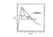
して、圧縮強度(σc0)時の最大応力と最大応力後にその50%応力に達した点を結んだ
直線の勾配により下降勾配(Edes )を求めることとした。この結果を図2に示す。
Therefore, similarly, the maximum stress at compressive strength (σ c0 ) is considered to be the most average evaluation of all the experimental results for confined concrete specimens using transverse restraint bars of various concrete strengths and various yield strengths. The descending slope (E des ) was determined from the slope of the straight line connecting the points that reached 50% stress after the maximum stress. The result is shown in FIG.
この下降勾配(Edes )と有効拘束圧(pe )の関係を、実験結果の回帰式として得た
ものが下記の式7となる。
![]()
![]()
前記の式5〜式7で得られた、σcc、εccおよびEdes の3つのパラメータをもとに、
コンファインドコンクリートの応力ーひずみ関係を下記の式8.1〜式8.2のように定
式化した。
The stress-strain relationship of the confined concrete was formulated as shown in the following formulas 8.1 to 8.2.
上記(式8.1,式8.2)を提案式として、前記の各種強度のコンクリートまたは横
拘束筋を用いた供試体の実験挙動と比較したところ極めて類似した挙動を示した。この結
果の一部を図3に示す。
When the above (Formula 8.1, Formula 8.2) was used as a proposed formula and compared with the experimental behavior of the specimens using the above-mentioned various strength concrete or lateral restraint bars, they showed very similar behavior. A part of the result is shown in FIG.
以上のように、使用されるコンクリートおよび横拘束筋の強度・ひずみ、および横拘束
筋の配筋構造から定まる有効横拘束圧(pe )を導入することで、RC柱の応力ーひずみ
関係を、コンクリートおよび横拘束筋の強度によらず定式化できることがわかった。すな
わち、本発明で定義した有効横拘束圧(pe )を導入すれば、式1〜式8を計算するだけ
で、繰返し計算や使い分けをせずに、コンファインドコンクリートの応力―ひずみ挙動を
把握できる。
As described above, by introducing the effective lateral restraint pressure ( pe ) determined from the strength and strain of the concrete and lateral restraint bars used and the reinforcement structure of the lateral restraint bars, the stress-strain relationship of the RC column can be reduced. It was found that it can be formulated regardless of the strength of concrete and lateral restraint bars. In other words, if the effective lateral restraint pressure ( pe ) defined in the present invention is introduced, the stress-strain behavior of the confined concrete can be grasped by simply calculating Equations 1 to 8 without repeated calculations and proper use. it can.
ところで、高耐力のRC柱部材を設計する場合、高強度コンクリートを用いることが考
えられるが、コンクリート強度が増加すると相対的にコンファインド効果が低減すること
が知られている。一方、横拘束筋の強度を増加させてもコンファインドコンクリートの圧
縮強度はほとんど増加しない。
By the way, when designing a RC column member having a high yield strength, it is conceivable to use high-strength concrete, but it is known that the confining effect is relatively reduced as the concrete strength increases. On the other hand, even if the strength of the lateral restraint bars is increased, the compressive strength of the confined concrete hardly increases.
しかし、最大圧縮応力後の下降勾配は、横拘束筋を高強度化することによりより穏やか
となり、特に横拘束筋体積比(ρs )が2.0%以上の場合、図4に示すように、圧縮靭
性が大きく改善される。従って、本発明における高耐力のRC柱状部材では、コンクリー
トの圧縮強度が39MPa以上の高強度コンクリートであり、かつ前記横拘束筋の引張強
度317MPa以上の高張力鋼を体積比で2.0%以上とした。なお、外周の横拘束筋の
かぶりの有無の影響は小さい。
However, the descending gradient after the maximum compressive stress becomes milder by increasing the strength of the lateral restraint muscle, and particularly when the lateral restraint muscle volume ratio (ρ s ) is 2.0% or more, as shown in FIG. , Compression toughness is greatly improved. Therefore, in the high yield strength RC columnar member in the present invention, the compressive strength of the concrete is high strength concrete of 39 MPa or more, and the high strength steel having the tensile strength of the lateral restraint bar of 317 MPa or more is 2.0% or more by volume ratio. It was. In addition, the influence of the presence or absence of the covering of the lateral restraint bars on the outer periphery is small.
一方、横拘束筋の配筋方法を変えることも有効である(図5参照)。この場合、横拘束
筋体積比が0.9%と小さくとも、外周筋のみの試験体より、断面中央部に中間帯鉄筋を
配し、田型とした試験体のほうが、圧縮強度、圧縮時のひずみ、下降勾配といった横拘束
効果が大きく現れる。以上のように、本発明では、使用材料の材料特性と配筋構造から、
容易に高耐力のRC柱部材を提供できる。
On the other hand, it is also effective to change the arrangement method of the lateral constraint muscles (see FIG. 5). In this case, even when the volume ratio of the lateral restraint bars is as small as 0.9%, the test piece with the intermediate band reinforcing bar in the center of the cross section and the pad-shaped test piece is more compressive strength and compressive than the test piece with only the outer peripheral bars. Lateral restraint effects such as strain and descending slope are greatly manifested. As described above, in the present invention, from the material characteristics of the materials used and the bar arrangement structure,
An RC pillar member having a high yield strength can be easily provided.
図6は、本発明による圧縮曲げ部材の応力ーひずみ関係をもとに、RC柱設計のための
評価方法をフロー化したものである。各数式はこれまで述べた式番号に対応している。図
7は、本発明の評価手法による建物等の構造解析システムの構成図である。特別な繰返し
計算が必要でないため、一般の汎用計算ソフトで電子媒体を提供できる。
FIG. 6 is a flow chart of an evaluation method for RC column design based on the stress-strain relationship of the compression bending member according to the present invention. Each formula corresponds to the formula number described so far. FIG. 7 is a configuration diagram of a structural analysis system for a building or the like according to the evaluation method of the present invention. Since no special repetitive calculation is required, an electronic medium can be provided by general general-purpose calculation software.
pe 有効横拘束圧
ke 有効横拘束係数
ρw 横拘束筋面積比
fs,c 圧縮強度発現時の横拘束筋作用応力
σck コンクリートの強度
ρs 横拘束筋体積比
σsy 横拘束筋の降伏強度
pe effective lateral restraint pressure k e effective lateral restraint coefficient ρ w lateral restraint bar area ratio f s, c lateral restraint muscle acting stress when compressive strength is expressed σ ck concrete strength ρ s lateral restraint bar volume ratio σ sy lateral restraint bar Yield strength of
Claims (2)
横拘束筋の断面諸数から求められる有効横拘束係数(ke )と、無拘束コンクリートおよ
び横拘束筋の力学的諸数から求められる圧縮強度発現時の横拘束筋作用応力(fs,c )と
に基づく式
pe =ke ・ρw ・fs,c
から有効横拘束圧(pe )を求め、該有効横拘束圧(pe )をパラメーターとして無拘束
コンクリートの圧縮強度(σc0)と横拘束コンクリートの圧縮強度(σcc)との関係、無
拘束コンクリートの最大軸ひずみ(εc0)と横拘束コンクリートの最大軸ひずみ(εcc)
との関係及び無拘束コンクリートの圧縮強度(σc0)と応力の下降勾配(Edes )との関
係を求め、上記関係に基づき横拘束筋を有する鉄筋コンクリート柱状部材の応力ーひずみ
関係の挙動を求めることを特徴とする横拘束筋を有する鉄筋コンクリート柱状部材の解析
方法。 In the reinforced concrete columnar member with lateral restraint bars, the area ratio (ρ w ) of the lateral restraint bars,
The effective lateral restraint coefficient (k e ) obtained from the number of cross-sections of the lateral restraint bars and the stress acting on the lateral restraint muscles (f s, c ) And formula based on
p e = k e · ρ w · f s, c
From this, the effective lateral restraint pressure ( pe ) is obtained and the relation between the compressive strength (σ c0 ) of unconstrained concrete and the compressive strength (σ cc ) of laterally constrained concrete using the effective lateral restraint pressure ( pe ) as a parameter. Maximum axial strain of constrained concrete (ε c0 ) and maximum axial strain of laterally constrained concrete (ε cc )
And the relationship between the compressive strength (σ c0 ) of unconstrained concrete and the descending slope of stress (E des ), and the behavior of the stress-strain relationship of a reinforced concrete columnar member with laterally constrained bars based on the above relationship A method for analyzing a reinforced concrete columnar member having lateral constraining bars.
ターにより実行させるためのプログラムを記録した記録媒体。 The recording medium which recorded the program for making the computer execute the analysis method of the reinforced concrete columnar member which has a lateral constrained reinforcement of Claim 1.
Priority Applications (1)
| Application Number | Priority Date | Filing Date | Title |
|---|---|---|---|
| JP2004235749A JP4855659B2 (en) | 2004-08-13 | 2004-08-13 | Method for analyzing reinforced concrete columnar member having lateral restraint bars and recording medium on which a program for causing a computer to execute the analysis method is recorded |
Applications Claiming Priority (1)
| Application Number | Priority Date | Filing Date | Title |
|---|---|---|---|
| JP2004235749A JP4855659B2 (en) | 2004-08-13 | 2004-08-13 | Method for analyzing reinforced concrete columnar member having lateral restraint bars and recording medium on which a program for causing a computer to execute the analysis method is recorded |
Publications (2)
| Publication Number | Publication Date |
|---|---|
| JP2006052594A JP2006052594A (en) | 2006-02-23 |
| JP4855659B2 true JP4855659B2 (en) | 2012-01-18 |
Family
ID=36030242
Family Applications (1)
| Application Number | Title | Priority Date | Filing Date |
|---|---|---|---|
| JP2004235749A Active JP4855659B2 (en) | 2004-08-13 | 2004-08-13 | Method for analyzing reinforced concrete columnar member having lateral restraint bars and recording medium on which a program for causing a computer to execute the analysis method is recorded |
Country Status (1)
| Country | Link |
|---|---|
| JP (1) | JP4855659B2 (en) |
Family Cites Families (5)
| Publication number | Priority date | Publication date | Assignee | Title |
|---|---|---|---|---|
| JPS60220710A (en) * | 1984-04-18 | 1985-11-05 | 電気化学工業株式会社 | Ultra-high strength prestressed concrete member |
| JPS62215717A (en) * | 1986-03-14 | 1987-09-22 | Kansai Asano Paul Kk | Touch pc pile of high bending and super high bending strength |
| JPS62280418A (en) * | 1986-05-30 | 1987-12-05 | Kansai Asano Paul Kk | High-bending yield, superhigh-bending yield, tough, centrifugally formed prestressed concrete pile |
| JPH08260565A (en) * | 1995-03-20 | 1996-10-08 | Kawatetsu Techno Wire Kk | Reinforced concrete wall column |
| JP3603742B2 (en) * | 2000-04-11 | 2004-12-22 | 株式会社大林組 | Analysis method for reinforced concrete column, analysis system for reinforced concrete column, and recording medium recording computer program for executing analysis method for reinforced concrete column |
-
2004
- 2004-08-13 JP JP2004235749A patent/JP4855659B2/en active Active
Also Published As
| Publication number | Publication date |
|---|---|
| JP2006052594A (en) | 2006-02-23 |
Similar Documents
| Publication | Publication Date | Title |
|---|---|---|
| Alavi-Dehkordi et al. | Effects of high-strength reinforcing bars and concrete on seismic behavior of RC beam-column joints | |
| Wang et al. | Experimental investigation and modeling of cyclic behavior of high strength steel | |
| Dundar et al. | Behaviour of reinforced and concrete-encased composite columns subjected to biaxial bending and axial load | |
| Rahnavard et al. | Concrete-filled cold-formed steel (CF-CFS) built-up columns under compression: Test and design | |
| Prakash et al. | Seismic performance of circular RC columns subjected to axial force, bending, and torsion with low and moderate shear | |
| Afsar Dizaj et al. | Numerical investigation of the influence of cross-sectional shape and corrosion damage on failure mechanisms of RC bridge piers under earthquake loading | |
| Kim et al. | Performance assessment of reinforced concrete bridge columns using a damage index | |
| Zhou et al. | Concrete-filled double-skin aluminum circular hollow section stub columns | |
| Amiri et al. | Investigation of the opening effects on the behavior of concrete beams without additional reinforcement in opening region using fem method | |
| Jiang et al. | Seismic damage assessment of RC members by a modified Park-Ang model | |
| Quang et al. | Behavior of high-performance fiber-reinforced cement composite columns subjected to horizontal biaxial and axial loads | |
| Tu et al. | Behavior and general design method of concrete-filled high-strength steel tube (CFHST) columns | |
| Yang et al. | Numerical simulation of bond degradation subjected to corrosion-induced crack by simplified rebar and interface model using RBSM | |
| Imran et al. | On the confined high-strength concrete and need of future research | |
| Aldabagh et al. | Low-cycle fatigue performance of high-strength steel reinforcing bars considering the effect of inelastic buckling | |
| Hu et al. | Corrosion influences on monotonic properties of ultra-high-strength reinforcing steels | |
| Carrillo et al. | Stiffness degradation model of thin and lightly reinforced concrete walls for housing | |
| Zhong et al. | Probabilistic Seismic drift-based capacity model of unbonded prestressed reinforced concrete columns: Prediction model and dispersion | |
| Ngo et al. | Expected maximum moment of multi-spiral columns | |
| Derseh et al. | Finite element analysis of the response of conventional and special reinforcement detailed concrete beams subjected to impact loads | |
| Kashani et al. | A multi-mechanical nonlinear fibre beam-column model for corroded columns | |
| Ghanooni-Bagha | Influence of chloride corrosion on tension capacity of rebars | |
| Kim et al. | Evaluation of behavior and strength of prestressed concrete deep beams using nonlinear analysis | |
| JP4855659B2 (en) | Method for analyzing reinforced concrete columnar member having lateral restraint bars and recording medium on which a program for causing a computer to execute the analysis method is recorded | |
| Belarbi et al. | Effect of spiral reinforcement on flexural-sheartorsional seismic behavior of reinforced concrete circular bridge columns |
Legal Events
| Date | Code | Title | Description |
|---|---|---|---|
| A621 | Written request for application examination |
Free format text: JAPANESE INTERMEDIATE CODE: A621 Effective date: 20070806 |
|
| A977 | Report on retrieval |
Free format text: JAPANESE INTERMEDIATE CODE: A971007 Effective date: 20091203 |
|
| A131 | Notification of reasons for refusal |
Free format text: JAPANESE INTERMEDIATE CODE: A131 Effective date: 20091215 |
|
| A521 | Request for written amendment filed |
Free format text: JAPANESE INTERMEDIATE CODE: A523 Effective date: 20100215 |
|
| A131 | Notification of reasons for refusal |
Free format text: JAPANESE INTERMEDIATE CODE: A131 Effective date: 20100907 |
|
| A521 | Request for written amendment filed |
Free format text: JAPANESE INTERMEDIATE CODE: A523 Effective date: 20101101 |
|
| A80 | Written request to apply exceptions to lack of novelty of invention |
Free format text: JAPANESE INTERMEDIATE CODE: A80 Effective date: 20110223 |
|
| TRDD | Decision of grant or rejection written | ||
| A01 | Written decision to grant a patent or to grant a registration (utility model) |
Free format text: JAPANESE INTERMEDIATE CODE: A01 Effective date: 20110920 |
|
| A01 | Written decision to grant a patent or to grant a registration (utility model) |
Free format text: JAPANESE INTERMEDIATE CODE: A01 |
|
| A61 | First payment of annual fees (during grant procedure) |
Free format text: JAPANESE INTERMEDIATE CODE: A61 Effective date: 20111027 |
|
| FPAY | Renewal fee payment (event date is renewal date of database) |
Free format text: PAYMENT UNTIL: 20141104 Year of fee payment: 3 |
|
| R150 | Certificate of patent or registration of utility model |
Ref document number: 4855659 Country of ref document: JP Free format text: JAPANESE INTERMEDIATE CODE: R150 Free format text: JAPANESE INTERMEDIATE CODE: R150 |
|
| R250 | Receipt of annual fees |
Free format text: JAPANESE INTERMEDIATE CODE: R250 |
|
| R250 | Receipt of annual fees |
Free format text: JAPANESE INTERMEDIATE CODE: R250 |
|
| R250 | Receipt of annual fees |
Free format text: JAPANESE INTERMEDIATE CODE: R250 |
|
| R250 | Receipt of annual fees |
Free format text: JAPANESE INTERMEDIATE CODE: R250 |
|
| R250 | Receipt of annual fees |
Free format text: JAPANESE INTERMEDIATE CODE: R250 |
|
| R250 | Receipt of annual fees |
Free format text: JAPANESE INTERMEDIATE CODE: R250 |
|
| R250 | Receipt of annual fees |
Free format text: JAPANESE INTERMEDIATE CODE: R250 |
|
| R250 | Receipt of annual fees |
Free format text: JAPANESE INTERMEDIATE CODE: R250 |
|
| R250 | Receipt of annual fees |
Free format text: JAPANESE INTERMEDIATE CODE: R250 |
|
| R250 | Receipt of annual fees |
Free format text: JAPANESE INTERMEDIATE CODE: R250 |