JP4853469B2 - Piston for internal combustion engine and internal combustion engine - Google Patents
Piston for internal combustion engine and internal combustion engine Download PDFInfo
- Publication number
- JP4853469B2 JP4853469B2 JP2007313725A JP2007313725A JP4853469B2 JP 4853469 B2 JP4853469 B2 JP 4853469B2 JP 2007313725 A JP2007313725 A JP 2007313725A JP 2007313725 A JP2007313725 A JP 2007313725A JP 4853469 B2 JP4853469 B2 JP 4853469B2
- Authority
- JP
- Japan
- Prior art keywords
- piston
- skirt
- pulling
- internal combustion
- combustion engine
- Prior art date
- Legal status (The legal status is an assumption and is not a legal conclusion. Google has not performed a legal analysis and makes no representation as to the accuracy of the status listed.)
- Expired - Fee Related
Links
Images


Description
本発明は、シリンダ内を往復運動する内燃機関用ピストン、及びピストンを備える内燃機関に関する。 The present invention relates to a piston for an internal combustion engine that reciprocates in a cylinder, and an internal combustion engine including the piston.
内燃機関のピストンは移動部材であるため、エンジン実働時において冷却水等で直接冷却することが困難である。例えば、シリンダに設けられたウォータジャケット内の冷却水で冷却されたシリンダと接触しながら摺動することで、ピストンヘッドの熱をシリンダに放熱している。また、オイルジェット等を有する内燃機関では、ピストンの内側へ向けて噴射されたオイルに放熱している。 Since the piston of the internal combustion engine is a moving member, it is difficult to directly cool it with cooling water or the like during engine operation. For example, the piston head heat is radiated to the cylinder by sliding while making contact with the cylinder cooled by the cooling water in the water jacket provided in the cylinder. Further, in an internal combustion engine having an oil jet or the like, heat is radiated to the oil injected toward the inside of the piston.
現行のレシプロ機関では、ピストン慣性力がピストンをシリンダに押し付ける側圧力(スラスト力)の発生要因の1つになっているので、ピストンをできうる限り軽くすることが求められる。また、ピストン頂部の熱を速やかに拡散させるために熱伝導率の高い材料で製作される。このため、内燃機関に使用されるピストンは、一般的にアルミニウム合金で製作される。一方、ピストンが挿入されるシリンダは、アルミニウム合金との耐焼き性において良好な特性を有する鋳鉄が使用される。シリンダは、シリンダブロックごと鋳鉄を用いる場合と、鋳鉄製ライナをアルミニウム合金で鋳包む場合とが一般的であるが、いずれの場合においても熱膨張係数がピストンのアルミニウム合金よりも小さくなる。加えて、燃焼の熱の一部はピストンを介してシリンダに放熱されるので、ピストンの方がシリンダよりも温度が高くなるのが一般的である。 In the current reciprocating engine, the piston inertia force is one of the generation factors of the side pressure (thrust force) that presses the piston against the cylinder. Therefore, it is required to make the piston as light as possible. Moreover, in order to diffuse the heat | fever of a piston top part rapidly, it manufactures with a material with high heat conductivity. For this reason, pistons used in internal combustion engines are generally made of an aluminum alloy. On the other hand, the cylinder into which the piston is inserted uses cast iron having good characteristics in terms of bake resistance with an aluminum alloy. In general, a cylinder uses cast iron for each cylinder block, and a cast iron liner is cast with an aluminum alloy. In either case, the coefficient of thermal expansion is smaller than that of the piston aluminum alloy. In addition, since a part of the heat of combustion is dissipated to the cylinder through the piston, the temperature of the piston is generally higher than that of the cylinder.
よって、エンジン実働時においては、ピストンの方が高温である上に熱膨張係数が大きい材料で製作されているので、ピストンの熱膨張によってピストンスカート部がシリンダに対して締まり嵌めになりやすい。ピストンスカート部がシリンダに対して締まり嵌めになると、ピストンスカート部での摩擦損失が増大する。逆に、ピストン高温時の締まり嵌めを回避するために、常温時のピストンとシリンダとの間のクリアランスを大きくすると、エンジン冷間時においてピストンがシリンダの中を蛇行して、振動・騒音の原因となる。 Therefore, when the engine is actually operated, the piston is made of a material having a higher temperature and a larger thermal expansion coefficient, and therefore, the piston skirt portion is likely to be tightly fitted to the cylinder due to the thermal expansion of the piston. When the piston skirt portion is an interference fit with the cylinder, the friction loss at the piston skirt portion increases. Conversely, if the clearance between the piston and the cylinder at room temperature is increased to avoid an interference fit when the piston is hot, the piston will meander in the cylinder when the engine is cold, causing vibration and noise. It becomes.
上記の問題点の解決を図るために、ピストンヘッド部とピストンスカート部との間にスリット孔を形成したピストンが提案されている。ピストンヘッド部とピストンスカート部との間にスリット孔を形成することで、ピストンの熱膨張に伴ってピストンヘッド部がピストン径方向外側へ変位しても、ピストンスカート部がピストンヘッド部につられてピストン径方向外側へ変位するのが抑制されるので、ピストンスカート部がシリンダに対して締まり嵌めになるのが抑制される。 In order to solve the above problems, a piston in which a slit hole is formed between a piston head portion and a piston skirt portion has been proposed. By forming a slit hole between the piston head part and the piston skirt part, even if the piston head part is displaced outward in the radial direction of the piston due to the thermal expansion of the piston, the piston skirt part is attached to the piston head part. Since displacement to the piston radial direction outside is suppressed, it is suppressed that a piston skirt part becomes an interference fit to a cylinder.
また、ストラットと呼ばれる鋼製の部材をピストン内に鋳込むことでピストンの形状変化を抑制する手法が提案されている。その応用例として、下記特許文献1が挙げられる。
In addition, there has been proposed a method of suppressing a piston shape change by casting a steel member called a strut into the piston. The following
ピストンの往復運動による振動・騒音の増大を招くことなくピストンスカート部での摩擦損失を低減するためには、ピストンの熱膨張時におけるピストンスカート部の径方向変位を調節できることが望ましい。ピストンヘッド部とピストンスカート部との間にスリット孔を形成したピストンにおいては、スリット孔によってピストンスカート部の径方向外側への変位を抑制することは可能であるが、ピストンスカート部の径方向内側への変位をスリット孔によって調節することは困難である。また、ストラット付きピストンの場合は、アルミニウムより熱膨張係数の小さい鋼材がストラットとして利用されるが、ピストン重量の増大と、異種金属を鋳込む必要があるため、構造が複雑化して製造コストの増大を招くことになる。 In order to reduce the friction loss at the piston skirt portion without increasing vibration and noise due to the reciprocating motion of the piston, it is desirable to be able to adjust the radial displacement of the piston skirt portion during thermal expansion of the piston. In a piston with a slit hole formed between the piston head part and the piston skirt part, it is possible to suppress the displacement of the piston skirt part to the outside in the radial direction by the slit hole. It is difficult to adjust the displacement to the slit hole. In the case of pistons with struts, steel materials with a smaller thermal expansion coefficient than aluminum are used as struts. However, because the piston weight is increased and dissimilar metals need to be cast, the structure becomes complicated and manufacturing costs increase. Will be invited.
本発明は、構造の複雑化及び振動・騒音の増大を招くことなく、ピストンスカート部での摩擦損失を低減することができる内燃機関用ピストン及び内燃機関を提供することを目的とする。 It is an object of the present invention to provide a piston for an internal combustion engine and an internal combustion engine that can reduce friction loss at a piston skirt without causing a complicated structure and an increase in vibration and noise.
本発明に係る内燃機関用ピストン及び内燃機関は、上述した目的を達成するために以下の手段を採った。 The internal combustion engine piston and internal combustion engine according to the present invention employ the following means in order to achieve the above-described object.
本発明に係る内燃機関用ピストンは、ピストン頂面を含むピストンヘッド部と、ピストンヘッド部より下方の位置でピストン軸方向と垂直方向に対向配置された一対のピストンピンボス部であって、その各々にピストンピンが嵌入されるピストンピン孔が形成された一対のピストンピンボス部と、ピストンヘッド部より下方で且つピストン外周部に設けられたピストンスカート部であって、その一端部がピストンピンボス部の一方に連結され、その他端部がピストンピンボス部の他方に連結され、その一端部から他端部にかけてピストン周方向に沿って湾曲した形状を有するピストンスカート部と、ピストンスカート部の内側に配置されたスカート牽引部であって、その一端部がピストンピンボス部の一方に連結され、その他端部がピストンピンボス部の他方に連結され、その一端部と他端部との間でピストンスカート部側へ湾曲した形状を有するスカート牽引部と、ピストンスカート部とスカート牽引部とを連結する連結部と、を備え、スカート牽引部は、一対のピストンピンボス部が互いに離れる方向へ変位するのに応じてピストン径方向内側へ変位することで、ピストンスカート部をピストン径方向内側へ牽引し、スカート牽引部の曲率がピストンスカート部の曲率と異なることを要旨とする。 A piston for an internal combustion engine according to the present invention includes a piston head portion including a piston top surface, and a pair of piston pin boss portions disposed opposite to each other in a direction perpendicular to the piston axial direction at a position below the piston head portion. A pair of piston pin bosses formed with piston pin holes into which the piston pins are fitted, and a piston skirt provided below the piston head and on the outer periphery of the piston, one end of which is the piston pin boss One end is connected to the other end, and the other end is connected to the other end of the piston pin boss. The piston skirt has a shape curved from one end to the other end along the circumferential direction of the piston, and is disposed inside the piston skirt. One end of the skirt is connected to one of the piston pin bosses, and the other end is a piston. A skirt pulling portion that is connected to the other end of the embossed portion and has a shape curved toward the piston skirt portion between the one end and the other end, and a connecting portion that connects the piston skirt and the skirt pulling portion. The skirt pulling part is pulled inward in the radial direction of the piston as the pair of piston pin bosses move away from each other, pulling the piston skirt inward in the radial direction of the piston, and the curvature of the skirt pulling part Is different from the curvature of the piston skirt.
本発明の一態様では、スカート牽引部の曲率がピストンスカート部の曲率よりも小さいことが好適である。 In one aspect of the present invention, it is preferable that the curvature of the skirt pulling portion is smaller than the curvature of the piston skirt portion.
また、本発明に係る内燃機関用ピストンは、ピストン頂面を含むピストンヘッド部と、ピストンヘッド部より下方の位置でピストン軸方向と垂直方向に対向配置された一対のピストンピンボス部であって、その各々にピストンピンが嵌入されるピストンピン孔が形成された一対のピストンピンボス部と、ピストンヘッド部より下方で且つピストン外周部に設けられたピストンスカート部であって、その一端部がピストンピンボス部の一方に連結され、その他端部がピストンピンボス部の他方に連結され、その一端部から他端部にかけてピストン周方向に沿って湾曲した形状を有するピストンスカート部と、ピストンスカート部の内側に配置されたスカート牽引部であって、その一端部がピストンピンボス部の一方に連結され、その他端部がピストンピンボス部の他方に連結され、その一端部と他端部との間でピストンスカート部側へ張り出した形状を有するスカート牽引部と、ピストンスカート部とスカート牽引部とを連結する連結部と、を備え、スカート牽引部は、一対のピストンピンボス部が互いに離れる方向へ変位するのに応じてピストン径方向内側へ変位することで、ピストンスカート部をピストン径方向内側へ牽引し、スカート牽引部における、連結部に連結された部位と一端部とを結ぶ平面と、当該部位と他端部とを結ぶ平面との成す角度は、ピストンスカート部における、連結部に連結された部位と一端部とを結ぶ平面と、当該部位と他端部とを結ぶ平面との成す角度と異なることを要旨とする。 Further, the piston for an internal combustion engine according to the present invention is a piston head part including a piston top surface, and a pair of piston pin boss parts arranged to be opposed to the piston axis direction at a position below the piston head part, A pair of piston pin bosses each formed with a piston pin hole into which a piston pin is fitted, and a piston skirt provided below the piston head and on the outer periphery of the piston, one end of which is a piston pin boss A piston skirt having a shape curved along the circumferential direction of the piston from one end to the other end, and connected to the other end of the piston pin boss. One end of the skirt pulling portion is connected to one of the piston pin bosses, and the other end is a pin. A skirt pulling portion connected to the other of the ton pin boss portions and having a shape projecting toward the piston skirt portion between one end portion and the other end portion thereof, and a connecting portion connecting the piston skirt portion and the skirt pulling portion. The skirt pulling part is pulled inward in the piston radial direction in accordance with the displacement of the pair of piston pin bosses in the direction away from each other, thereby pulling the piston skirt part inward in the radial direction of the piston. The angle formed by the plane connecting the part connected to the connecting part and one end and the plane connecting the part and the other end connects the part connected to the connecting part and one end in the piston skirt part. The gist is that the angle is different from the angle formed by the plane and the plane connecting the part and the other end.
本発明の一態様では、スカート牽引部における、連結部に連結された部位と一端部とを結ぶ平面と、当該部位と他端部とを結ぶ平面との成す角度は、ピストンスカート部における、連結部に連結された部位と一端部とを結ぶ平面と、当該部位と他端部とを結ぶ平面との成す角度よりも大きいことが好適である。 In one aspect of the present invention, the angle formed between the plane connecting the portion connected to the connecting portion and one end of the skirt pulling portion and the plane connecting the portion and the other end is determined by the connection in the piston skirt portion. It is preferable that the angle formed by a plane connecting the part connected to the part and one end and a plane connecting the part and the other end is larger.
本発明の一態様では、連結部は、ピストン周方向に関するピストンスカート部の中央部とピストン周方向に関するスカート牽引部の中央部とを連結することが好適である。 In one aspect of the present invention, it is preferable that the connecting portion connects the central portion of the piston skirt portion with respect to the piston circumferential direction and the central portion of the skirt pulling portion with respect to the piston circumferential direction.
本発明の一態様では、ピストンヘッド部とピストンスカート部との間には、ピストンが熱膨張する場合にピストンヘッド部のピストン径方向変位に伴うピストンスカート部のピストン径方向変位を抑制するためのスリット孔が形成されていることが好適である。 In one aspect of the present invention, when the piston thermally expands between the piston head portion and the piston skirt portion, the displacement of the piston skirt portion in the piston radial direction accompanying the displacement of the piston head portion in the piston radial direction is suppressed. It is preferable that a slit hole is formed.
また、本発明に係る内燃機関は、シリンダ内を往復運動するピストンを備える内燃機関であって、前記ピストンが、本発明に係る内燃機関用ピストンであることを要旨とする。 Moreover, the internal combustion engine which concerns on this invention is an internal combustion engine provided with the piston which reciprocates within a cylinder, Comprising: Let the said piston be the piston for internal combustion engines which concerns on this invention.
本発明によれば、一対のピストンピンボス部が互いに離れる方向へ変位するのに伴って生じる、ピストンスカート部のピストン径方向内側への変位を調節することができるので、ピストンの熱膨張時におけるピストンスカート部のピストン径方向変位を調節することができる。その結果、ピストンの構造の複雑化及びピストンの往復運動による振動・騒音の増大を招くことなく、ピストンスカート部での摩擦損失を低減することができる。 According to the present invention, it is possible to adjust the displacement of the piston skirt portion inward in the radial direction of the piston, which occurs as the pair of piston pin boss portions are displaced in the direction away from each other. The piston radial displacement of the skirt portion can be adjusted. As a result, the friction loss at the piston skirt can be reduced without complicating the piston structure and increasing vibration and noise due to the reciprocating motion of the piston.
以下、本発明を実施するための形態(以下実施形態という)を図面に従って説明する。 DESCRIPTION OF EMBODIMENTS Hereinafter, embodiments for carrying out the present invention (hereinafter referred to as embodiments) will be described with reference to the drawings.
「実施形態1」
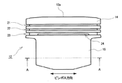
図1〜5は、本発明の実施形態1に係る内燃機関用ピストン12を備える内燃機関の概略構成を示す図である。図1はクランクシャフトの軸線方向から見た内燃機関の内部構成の概略を示す図であり、図2はクランクシャフトの軸線方向から見たピストン12の概略構成を示す断面図(ピストンスラスト方向の断面図)であり、図3はクランクシャフトの軸線方向及びシリンダ11の軸線方向と直交する方向から見たピストン12の概略構成を示す外観図(ピストンピンボス方向の外観図)であり、図4は図3のA−A断面図(シリンダ11の軸線方向下側から見た図)であり、図5は図2のA部の拡大図である。図1では、コネクティングロッドやクランクシャフトや動弁機構等の具体的構成の図示を省略しているが、公知の構成で実現可能である。本実施形態に係るピストン12は、シリンダ11内をその軸線方向に沿って往復運動するものであり、シリンダ11内のガスに面するピストン頂面12aを含むピストンヘッド部14と、ピストンヘッド部14より下方に設けられた一対のピストンピンボス部18−1,18−2と、ピストンヘッド部14より下方で且つピストン12外周部に設けられ、シリンダ内周壁11aに面する一対のピストンスカート部16と、を備える。ピストン12の材料としては、例えばアルミニウム合金等、熱伝導率の高い材料が用いられる。
“
FIGS. 1-5 is a figure which shows schematic structure of an internal combustion engine provided with the
一対のピストンピンボス部18−1,18−2は、ピストンヘッド部14の下面に連結されており、ピストンヘッド部14より下方の位置でピストン軸方向(シリンダ11の軸線方向に一致する)と垂直方向に互いに間隔を空けて対向配置されている。各ピストンピンボス部18−1,18−2には、ピストンピンが嵌入されるピストンピン孔19−1,19−2がそれぞれ形成されている。
The pair of piston pin boss portions 18-1 and 18-2 is connected to the lower surface of the
一対のピストンスカート部16は、ピストン12のスラスト面12b(エンジンの膨張行程において燃焼圧力がピストン12をシリンダ11へ押し付ける側圧力(スラスト力)が作用する面)及び反スラスト面12c(スラスト面12bと反対側の面)にそれぞれ設けられている。各ピストンスカート部16は、薄肉形状であり、ピストン周方向に関する一端部16aから他端部16bにかけてピストン周方向に沿って湾曲した形状を有する。各ピストンスカート部16の曲率は、シリンダ11のボア径により決まる。ピストン周方向に関する各ピストンスカート部16の一端部16aは、側壁部44−1を介してピストンピンボス部18−1に連結されており、ピストン周方向に関する各ピストンスカート部16の他端部16bは、側壁部44−2を介してピストンピンボス部18−2に連結されている。
The pair of
ピストン12(ピストンヘッド部14)の外周部には、ピストンリング(コンプレッションリング)が装着されるリング溝として、トップリング溝21及びセカンドリング溝22がピストン周方向に沿って形成されており、トップリング溝21及びセカンドリング溝22には、コンプレッションリングとしてトップリング31及びセカンドリング32がそれぞれ装着されている。ピストン12の外周部におけるピストンヘッド部14とピストンスカート部16との間には、ピストンリング(オイルリング33)が装着されるリング溝として、オイルリング溝23がピストン周方向に沿って形成されている。
A
図5に示すように、ピストンヘッド部14とピストンスカート部16との間には、オイルリング溝23に開口するスリット孔24がピストン周方向に沿って形成されている。ここでのスリット孔24は、ピストン12のスラスト面12b及び反スラスト面12cにそれぞれ形成されており、スリット孔24の長手方向はピストン周方向に一致している。このスリット孔24によって、ピストンヘッド部14とピストンスカート部16との間のピストン径方向に関する相対変位が許容され、ピストン12が熱膨張する場合に、ピストンヘッド部14のピストン径方向変位に伴って生じるピストンスカート部16のピストン径方向変位が抑制される。なお、図5は、スリット孔24がオイルリング溝23の底面23aの下方位置でオイルリング溝23に開口する例を示している。ただし、スリット孔24は、例えば図6に示すように、オイルリング溝23の底面23aの中央位置でオイルリング溝23に開口していてもよいし、例えば図7に示すように、オイルリング溝23のピストンスカート部16側の側面23cでオイルリング溝23に開口していてもよい。
As shown in FIG. 5, between the
本実施形態では、各ピストンスカート部16のピストン径方向内側には、ピストン12の熱膨張時に各ピストンスカート部16をピストン径方向内側へ牽引するための一対のスカート牽引部42が各ピストンスカート部16と間隔を空けて配置されている。ピストン周方向に関する各スカート牽引部42の一端部42aは、側壁部44−1を介してピストンピンボス部18−1に連結されており、ピストン周方向に関する各スカート牽引部42の他端部42bは、側壁部44−2を介してピストンピンボス部18−2に連結されている。各スカート牽引部42は、薄肉形状であり、ピストン周方向に関する中央部42cが一端部42aと他端部42bとを結ぶ平面よりもピストンスカート部16側(ピストン径方向外側)へ張り出しており、その一端部42aと他端部42bとの間でピストンスカート部16側へ湾曲した形状を有する。(熱膨張前における)各スカート牽引部42の曲率は、(熱膨張前における)各ピストンスカート部16の曲率と異なる。図4に示す例では、各スカート牽引部42の曲率が各ピストンスカート部16の曲率よりも小さい(各スカート牽引部42の曲率半径が各ピストンスカート部16の曲率半径よりも大きい)。その場合、ピストン周方向に関するスカート牽引部42の中央部42cとピストン周方向に関するピストンスカート部16の中央部16cとの距離は、スカート牽引部42の一端部42aとピストンスカート部16の一端部16aとの距離、及びスカート牽引部42の他端部42bとピストンスカート部16の他端部16bとの距離よりも長い。そして、本実施形態では、各ピストンスカート部16の内周壁と各スカート牽引部42の外周壁とを連結する一対の連結部45が設けられている。図4に示す例では、各連結部45は、ピストン周方向に関する各ピストンスカート部16の中央部16cとピストン周方向に関する各スカート牽引部42の中央部42cとを連結している。ただし、ピストンスカート部16における連結部45との連結部位、及びスカート牽引部42における連結部45との連結部位は、中央部16c,42cから若干ずれていてもかまわない。
In the present embodiment, a pair of
ピストンヘッド部14は高温の燃焼室に面しているのに対して、ピストンスカート部16は冷却水の流れるウォータジャケットを背部に有するシリンダ内周壁11aに接しているため、ピストンヘッド部14の方がピストンスカート部16より温度が高くなる。エンジン実働時においては、ピストン12は室温より高い温度になるため、ピストンスカート部16は熱膨張によってピストン径方向に変位する。一方、ピストンヘッド部14に連結された一対のピストンピンボス部18−1,18−2は、ピストンヘッド部14の熱膨張に伴ってピストン径方向外側に変位して互いに離れる。その際には、ピストンヘッド部14がピストン径方向外側へ変位(熱膨張)するのに伴って、ピストンヘッド部14に連結された各ピストンスカート部16が、ピストンヘッド部14につられてピストン径方向外側へ変位する。さらに、ピストンヘッド部14に連結された一対のピストンピンボス部18−1,18−2も、ピストンヘッド部14につられてピストン径方向外側へ変位して互いに離れる。その際には、ピストンピンボス部18−1,18−2に連結されたピストンスカート部16が曲率を有しているため、ピストンピンボス部18−1,18−2がピストン径方向外側(互いに離れる方向)へ変位するのに応じて、ピストンスカート部16の円弧が引き伸ばされる形になり、ピストンスカート部16(円弧)の中央部16cが元の形状よりピストン径方向内側へ変位することになる。このピストンスカート部16のピストン径方向内側への変位は、ピストンスカート部16の熱膨張を抑制する方向の変位となるため、ピストンスカート部16がシリンダ11に対して締まり嵌めになるのを抑制する方向に作用する。
The
本願発明者は、ピストンスカート部16の曲率とピストン径方向内側への変位との関係を調べるために、図8に示すように、略半円筒形状の部材66の曲率半径を変化させながら、部材66の両端部66a,66bをそれぞれ径方向外側へ変位させたときの中央部66cの径方向内側への変位を計算した。その計算結果を図9に示す。計算の際には、略半円筒形状の部材66をアルミニウム製とし、部材66の肉厚を1mmとし、変位前における両端部66a,66b間の距離Lを75mmとし、両端部66a,66bの径方向外側への変位を100μmずつとした。図9に示すように、部材66の曲率半径が増大する(部材66の曲率が減少する)ほど、中央部66cの径方向内側への変位量(逆変位量)が大きいことがわかる。したがって、ピストンピンボス部18−1,18−2が互いに離間する方向へ変位するのに伴って生じる、ピストンスカート部16のピストン径方向内側への変位は、ピストンスカート部16の曲率に応じて変化し、ピストンスカート部16の曲率が小さい(曲率半径が大きい)ほど大きくなる。しかし、ピストンスカート部16の曲率はシリンダ11のボア径によって必然的に決まるため、ピストンスカート部16の曲率によってピストンスカート部16のピストン径方向内側への変位を調節することは困難である。
In order to investigate the relationship between the curvature of the
これに対して本実施形態では、ピストンスカート部16の径方向内側に配置されたスカート牽引部42が曲率を有している(ピストンスカート部16側へ湾曲している)ため、ピストン12の熱膨張によりピストンピンボス部18−1,18−2が径方向外側(互いに離れる方向)へ変位するのに応じて、図10に示すように、ピストンピンボス部18−1,18−2に連結された各スカート牽引部42が引き伸ばされる形になり、各スカート牽引部42の中央部42cが元の形状よりピストン径方向内側へ変位することになる。このスカート牽引部42のピストン径方向内側への変位により、各スカート牽引部42に連結された各ピストンスカート部16が、ピストン径方向内側へ牽引されて変位する。ここでのピストンスカート部16のピストン径方向内側への変位については、スカート牽引部42のピストン径方向内側への変位を調節することで調節可能である。そして、図9から、スカート牽引部42のピストン径方向内側への変位については、スカート牽引部42の曲率を調節することで調節可能であり、スカート牽引部42の曲率が小さい(曲率半径が大きい)ほど大きくなる。さらに、スカート牽引部42の曲率については、シリンダ11のボア径(ピストンスカート部16の曲率)に関係なく、任意に設定することが可能である。したがって、スカート牽引部42の曲率を調節することで、ピストンピンボス部18−1,18−2が互いに離間する方向へ変位するのに伴って生じる、ピストンスカート部16のピストン径方向内側への変位を調節することができる。
On the other hand, in the present embodiment, the
本実施形態におけるスカート牽引部42及び連結部45がピストンスカート部16の径方向変位に与える影響を検討した計算結果を図11〜13に示す。図11は、スカート牽引部42及び連結部45が設けられていない場合において、ピストンピンボス部18−1,18−2を径方向外側へ変位させたときのピストンスカート部16の変形状態を示す。図12は、スカート牽引部42の曲率がピストンスカート部16の曲率よりも小さい(スカート牽引部42の曲率半径がピストンスカート部16の曲率半径よりも大きい)場合において、ピストンピンボス部18−1,18−2を径方向外側へ変位させたときのピストンスカート部16の変形状態を示す。図13は、スカート牽引部42の曲率がピストンスカート部16の曲率よりも大きい(スカート牽引部42の曲率半径がピストンスカート部16の曲率半径よりも小さい)場合において、ピストンピンボス部18−1,18−2を径方向外側へ変位させたときのピストンスカート部16の変形状態を示す。計算の際には、ピストン12をアルミニウム合金製とし、ピストンスカート部16及びスカート牽引部42の肉厚を2mmとし、変形前におけるピストンスカート部16の曲率半径を37.5mmとし、変形前におけるピストンスカート部16の両端部16a,16b間の距離を75mmとし、ピストンピンボス部18−1,18−2(両端部16a,16b)の径方向外側への変位を100μmずつとした。そして、図12に示す場合におけるスカート牽引部42の曲率半径を45mmとし、図13に示す場合におけるスカート牽引部42の曲率半径を30mmとした。
The calculation result which examined the influence which the
図11に示す場合は、ピストンスカート部16の中央部16cの径方向内側への変位量(逆変位量)は202μmであった。一方、図12に示す場合は、ピストンスカート部16の中央部16cの径方向内側への変位量(逆変位量)は、242μmであり、図11に示す場合より増大する。また、図13に示す場合は、ピストンスカート部16の中央部16cの径方向内側への変位量(逆変位量)は185μmであり、図11に示す場合より減少する。このように、スカート牽引部42の曲率をピストンスカート部16の曲率と異ならせることで、ピストンスカート部16のピストン径方向内側への変位を調節できることがわかる。さらに、スカート牽引部42の曲率をピストンスカート部16の曲率より小さくする(スカート牽引部42の曲率半径をピストンスカート部16の曲率半径より大きくする)ことで、ピストンスカート部16のピストン径方向内側への変位を増大できることがわかる。
In the case shown in FIG. 11, the displacement amount (reverse displacement amount) of the
以上説明したように、本実施形態によれば、ピストンスカート部16にその内側で連結されたスカート牽引部42は、ピストン12の熱膨張時に、ピストンピンボス部18−1,18−2が互いに離間する方向へ変位するのに応じてピストン径方向内側へ変位することで、ピストンスカート部16をピストン径方向内側へ牽引することができる。そして、スカート牽引部42の曲率については、シリンダ11のボア径(ピストンスカート部16の曲率)に関係なく、任意に設定することが可能である。そのため、スカート牽引部42の曲率をピストンスカート部16の曲率と異ならせることで、ピストンピンボス部18−1,18−2が互いに離間する方向へ変位するのに伴って生じる、ピストンスカート部16のピストン径方向内側への変位を調節することができ、ピストン12の熱膨張時におけるピストンスカート部16のピストン径方向変位を調節することができる。その際には、ストラット付きピストンのように異種金属を鋳込む必要もない。その結果、ピストン12の構造の複雑化及びピストン12の往復運動による振動・騒音の増大を招くことなく、ピストンスカート部16での摩擦損失を低減することができる。ピストンスカート部16での摩擦損失を低減することで、内燃機関の燃料消費率を向上させることができる。
As described above, according to the present embodiment, the
さらに、本実施形態によれば、スカート牽引部42の曲率をピストンスカート部16の曲率より小さくすることで、ピストンピンボス部18−1,18−2が互いに離間する方向へ変位するのに伴って生じる、ピストンスカート部16のピストン径方向内側への変位を増大させることができる。したがって、ピストン12の熱膨張時に、ピストンスカート部16がピストン径方向外側へ変位するのをさらに抑制することができ、ピストンスカート部16がシリンダ11に対して締まり嵌めになるのをさらに抑制することができる。その結果、ピストンスカート部16での摩擦損失をさらに低減することができる。
Furthermore, according to the present embodiment, by making the curvature of the
また、本実施形態によれば、ピストンヘッド部14とピストンスカート部16とがスリット孔24によって分離されているため、ピストン12の熱膨張時に、ピストンヘッド部14が径方向外側へ変位(熱膨張)しても、ピストンスカート部16がピストンヘッド部14につられてピストン径方向外側へ変位するのが抑制される。したがって、ピストンスカート部16がシリンダ11に対して締まり嵌めになるのをさらに抑制することができる。
Further, according to the present embodiment, since the
「実施形態2」
図14,15は、本発明の実施形態2に係る内燃機関用ピストン12の概略構成を示す図である。図14は図3のA−A断面図に相当する図(シリンダ11の軸線方向下側から見た図)であり、図15は図14のB部の拡大図である。以下の実施形態2の説明では、実施形態1と同様の構成または対応する構成には同一の符号を付し、重複する説明を省略する。
“
14 and 15 are diagrams showing a schematic configuration of a
本実施形態では、実施形態1と比較して、各スカート牽引部42は、連結部45に連結された中央部42cと側壁部44−1(ピストンピンボス部18−1)に連結された一端部42aとを繋ぐ平板状部材42dと、中央部42cと側壁部44−2(ピストンピンボス部18−2)に連結された他端部42bとを繋ぐ平板状部材42eと、を含んで構成されている。各スカート牽引部42の中央部42cは、一端部42aと他端部42bとを結ぶ平面よりもピストンスカート部16側(ピストン径方向外側)へ張り出しており、各スカート牽引部42は、その一端部42aと他端部42bとの間でピストンスカート部16側へ張り出した形状を有する。スカート牽引部42の中央部42cとピストンスカート部16の中央部16cとの距離は、スカート牽引部42の一端部42aとピストンスカート部16の一端部16aとの距離、及びスカート牽引部42の他端部42bとピストンスカート部16の他端部16bとの距離よりも長い。そのため、図15に示すように、各スカート牽引部42における平板状部材42d,42e同士の成す角度αは、各ピストンスカート部16における、連結部45に連結された中央部16cと側壁部44−1(ピストンピンボス部18−1)に連結された一端部16aとを結ぶ平面67と、中央部16cと側壁部44−2(ピストンピンボス部18−2)に連結された他端部16bとを結ぶ平面68との成す角度βと異なる。つまり、各スカート牽引部42における、中央部42cと一端部42aを結ぶ平面と、中央部42cと他端部42bを結ぶ平面との成す角度αは、各ピストンスカート部16における、中央部16cと一端部16aを結ぶ平面67と、中央部16cと他端部16bを結ぶ平面68との成す角度βと異なる。図14,15に示す例では、各スカート牽引部42における平板状部材42d,42e同士の成す角度(中央部42cと一端部42aを結ぶ平面と、中央部42cと他端部42bを結ぶ平面との成す角度)αは、各ピストンスカート部16における平面67,68同士の成す角度βよりも大きい(α>β)。このように、実施形態1ではスカート牽引部42をピストンスカート部16側へ湾曲させていたのに対して、本実施形態ではスカート牽引部42を、平板状部材42d,42eをピストンスカート部16側へ折り曲げた形状としている。
In the present embodiment, as compared with the first embodiment, each
本実施形態におけるピストン12の熱膨張時の動作も、実質的に実施形態1と同様である。つまり、ピストン12の熱膨張によりピストンピンボス部18−1,18−2が径方向外側(互いに離れる方向)へ変位するのに応じて、図16に示すように、各スカート牽引部42が引き伸ばされる形になり、各スカート牽引部42の中央部42cが元の形状よりピストン径方向内側へ変位することになる。このスカート牽引部42のピストン径方向内側への変位によって、各ピストンスカート部16をピストン径方向内側へ牽引して変位させることができる。ここでのピストンスカート部16のピストン径方向内側への変位については、スカート牽引部42における平板状部材42d,42e同士の成す角度αを調節することで調節可能であり、角度αが大きいほど大きくなる。そして、スカート牽引部42における平板状部材42d,42e同士の成す角度αについては、シリンダ11のボア径(ピストンスカート部16の曲率)に関係なく、任意に設定することが可能である。そのため、スカート牽引部42における平板状部材42d,42e同士の成す角度αをピストンスカート部16における平面67,68同士の成す角度βと異ならせることで、ピストンピンボス部18−1,18−2が互いに離間する方向へ変位するのに伴って生じる、ピストンスカート部16のピストン径方向内側への変位を調節することができ、ピストン12の熱膨張時におけるピストンスカート部16のピストン径方向変位を調節することができる。その結果、ピストン12の構造の複雑化及びピストン12の往復運動による振動・騒音の増大を招くことなく、ピストンスカート部16での摩擦損失を低減することができる。
The operation at the time of thermal expansion of the
さらに、本実施形態では、スカート牽引部42における平板状部材42d,42e同士の成す角度αをピストンスカート部16における平面67,68同士の成す角度βより大きくすることで、ピストンピンボス部18−1,18−2が互いに離間する方向へ変位するのに伴って生じる、ピストンスカート部16のピストン径方向内側への変位を増大させることができる。したがって、ピストン12の熱膨張時に、ピストンスカート部16がピストン径方向外側へ変位するのをさらに抑制することができ、ピストンスカート部16がシリンダ11に対して締まり嵌めになるのをさらに抑制することができる。その結果、ピストンスカート部16での摩擦損失をさらに低減することができる。
Further, in the present embodiment, the piston pin boss portion 18-1 is formed by making the angle α formed by the
以上の実施形態では、ピストンヘッド部14とピストンスカート部16との間にスリット孔24が形成されたピストン12に対して本発明を適用した場合について説明した。ただし、ピストンヘッド部14とピストンスカート部16との間にスリット孔24が形成されていないピストン12に対しても本発明を適用することが可能である。
In the above embodiment, the case where this invention was applied with respect to the
以上、本発明を実施するための形態について説明したが、本発明はこうした実施形態に何等限定されるものではなく、本発明の要旨を逸脱しない範囲内において、種々なる形態で実施し得ることは勿論である。 As mentioned above, although the form for implementing this invention was demonstrated, this invention is not limited to such embodiment at all, and it can implement with a various form in the range which does not deviate from the summary of this invention. Of course.
11 シリンダ、12 ピストン、12a ピストン頂面、14 ピストンヘッド部、16 ピストンスカート部、18−1,18−2 ピストンピンボス部、19−1,19−2 ピストンピン孔、21 トップリング溝、22 セカンドリング溝、23 オイルリング溝、24 スリット孔、31 トップリング、32 セカンドリング、33 オイルリング、42 スカート牽引部、44−1,44−2 側壁部、45 連結部。 11 Cylinder, 12 Piston, 12a Piston top surface, 14 Piston head, 16 Piston skirt, 18-1, 18-2 Piston pin boss, 19-1, 19-2 Piston pin hole, 21 Top ring groove, 22 Second Ring groove, 23 Oil ring groove, 24 Slit hole, 31 Top ring, 32 Second ring, 33 Oil ring, 42 Skirt pulling part, 44-1, 44-2 Side wall part, 45 Connecting part.
Claims (7)
ピストンヘッド部より下方の位置でピストン軸方向と垂直方向に対向配置された一対のピストンピンボス部であって、その各々にピストンピンが嵌入されるピストンピン孔が形成された一対のピストンピンボス部と、
ピストンヘッド部より下方で且つピストン外周部に設けられたピストンスカート部であって、その一端部がピストンピンボス部の一方に連結され、その他端部がピストンピンボス部の他方に連結され、その一端部から他端部にかけてピストン周方向に沿って湾曲した形状を有するピストンスカート部と、
ピストンスカート部の内側に配置されたスカート牽引部であって、その一端部がピストンピンボス部の一方に連結され、その他端部がピストンピンボス部の他方に連結され、その一端部と他端部との間でピストンスカート部側へ湾曲した形状を有するスカート牽引部と、
ピストンスカート部とスカート牽引部とを連結する連結部と、
を備え、
スカート牽引部は、一対のピストンピンボス部が互いに離れる方向へ変位するのに応じてピストン径方向内側へ変位することで、ピストンスカート部をピストン径方向内側へ牽引し、
スカート牽引部の曲率がピストンスカート部の曲率と異なる、内燃機関用ピストン。 A piston head including a piston top surface;
A pair of piston pin bosses disposed opposite to each other in a direction perpendicular to the piston axial direction at a position below the piston head part, and a pair of piston pin bosses each having a piston pin hole into which the piston pin is fitted; ,
A piston skirt provided below the piston head and on the outer periphery of the piston, one end of which is connected to one of the piston pin bosses, and the other end connected to the other of the piston pin bosses. A piston skirt having a shape curved along the circumferential direction of the piston from the other end to the other end;
A skirt pulling portion disposed inside the piston skirt portion, one end portion of which is connected to one of the piston pin boss portions, the other end portion is connected to the other of the piston pin boss portions, and one end portion and the other end portion thereof A skirt pulling portion having a shape curved to the piston skirt portion side between,
A connecting part for connecting the piston skirt part and the skirt pulling part;
With
The skirt pulling portion is pulled inward in the piston radial direction in accordance with the displacement of the pair of piston pin boss portions in the direction away from each other, thereby pulling the piston skirt portion inward in the piston radial direction,
A piston for an internal combustion engine in which the curvature of the skirt pulling portion is different from the curvature of the piston skirt portion.
スカート牽引部の曲率がピストンスカート部の曲率よりも小さい、内燃機関用ピストン。 A piston for an internal combustion engine according to claim 1,
A piston for an internal combustion engine in which the curvature of the skirt pulling portion is smaller than the curvature of the piston skirt portion.
ピストンヘッド部より下方の位置でピストン軸方向と垂直方向に対向配置された一対のピストンピンボス部であって、その各々にピストンピンが嵌入されるピストンピン孔が形成された一対のピストンピンボス部と、
ピストンヘッド部より下方で且つピストン外周部に設けられたピストンスカート部であって、その一端部がピストンピンボス部の一方に連結され、その他端部がピストンピンボス部の他方に連結され、その一端部から他端部にかけてピストン周方向に沿って湾曲した形状を有するピストンスカート部と、
ピストンスカート部の内側に配置されたスカート牽引部であって、その一端部がピストンピンボス部の一方に連結され、その他端部がピストンピンボス部の他方に連結され、その一端部と他端部との間でピストンスカート部側へ張り出した形状を有するスカート牽引部と、
ピストンスカート部とスカート牽引部とを連結する連結部と、
を備え、
スカート牽引部は、一対のピストンピンボス部が互いに離れる方向へ変位するのに応じてピストン径方向内側へ変位することで、ピストンスカート部をピストン径方向内側へ牽引し、
スカート牽引部における、連結部に連結された部位と一端部とを結ぶ平面と、当該部位と他端部とを結ぶ平面との成す角度は、ピストンスカート部における、連結部に連結された部位と一端部とを結ぶ平面と、当該部位と他端部とを結ぶ平面との成す角度と異なる、内燃機関用ピストン。 A piston head including a piston top surface;
A pair of piston pin bosses disposed opposite to each other in a direction perpendicular to the piston axial direction at a position below the piston head part, and a pair of piston pin bosses each having a piston pin hole into which the piston pin is fitted; ,
A piston skirt provided below the piston head and on the outer periphery of the piston, one end of which is connected to one of the piston pin bosses, and the other end connected to the other of the piston pin bosses. A piston skirt having a shape curved along the circumferential direction of the piston from the other end to the other end;
A skirt pulling portion disposed inside the piston skirt portion, one end portion of which is connected to one of the piston pin boss portions, the other end portion is connected to the other of the piston pin boss portions, and one end portion and the other end portion thereof A skirt pulling portion having a shape protruding to the piston skirt portion side between,
A connecting part for connecting the piston skirt part and the skirt pulling part;
With
The skirt pulling portion is pulled inward in the piston radial direction in accordance with the displacement of the pair of piston pin boss portions in the direction away from each other, thereby pulling the piston skirt portion inward in the piston radial direction,
In the skirt pulling portion, the angle formed by the plane connecting the part connected to the connecting part and one end part and the plane connecting the part and the other end part is the same as the part connected to the connecting part in the piston skirt part. A piston for an internal combustion engine, which is different in angle from a plane connecting one end and a plane connecting the part and the other end.
スカート牽引部における、連結部に連結された部位と一端部とを結ぶ平面と、当該部位と他端部とを結ぶ平面との成す角度は、ピストンスカート部における、連結部に連結された部位と一端部とを結ぶ平面と、当該部位と他端部とを結ぶ平面との成す角度よりも大きい、内燃機関用ピストン。 A piston for an internal combustion engine according to claim 3,
In the skirt pulling portion, the angle formed by the plane connecting the part connected to the connecting part and one end part and the plane connecting the part and the other end part is the same as the part connected to the connecting part in the piston skirt part. A piston for an internal combustion engine, which is larger than an angle formed by a plane connecting one end and a plane connecting the part and the other end.
連結部は、ピストン周方向に関するピストンスカート部の中央部とピストン周方向に関するスカート牽引部の中央部とを連結する、内燃機関用ピストン。 A piston for an internal combustion engine according to any one of claims 1 to 4,
The connecting portion is a piston for an internal combustion engine that connects the central portion of the piston skirt portion with respect to the piston circumferential direction and the central portion of the skirt pulling portion with respect to the piston circumferential direction.
ピストンヘッド部とピストンスカート部との間には、ピストンが熱膨張する場合にピストンヘッド部のピストン径方向変位に伴うピストンスカート部のピストン径方向変位を抑制するためのスリット孔が形成されている、内燃機関用ピストン。 A piston for an internal combustion engine according to any one of claims 1 to 5,
A slit hole is formed between the piston head portion and the piston skirt portion to suppress displacement of the piston skirt portion in the piston radial direction due to displacement of the piston head portion in the piston radial direction when the piston is thermally expanded. , Pistons for internal combustion engines.
前記ピストンが、請求項1〜6のいずれか1に記載の内燃機関用ピストンである、内燃機関。 An internal combustion engine comprising a piston that reciprocates in a cylinder,
An internal combustion engine, wherein the piston is the piston for an internal combustion engine according to any one of claims 1 to 6.
Priority Applications (1)
| Application Number | Priority Date | Filing Date | Title |
|---|---|---|---|
| JP2007313725A JP4853469B2 (en) | 2007-12-04 | 2007-12-04 | Piston for internal combustion engine and internal combustion engine |
Applications Claiming Priority (1)
| Application Number | Priority Date | Filing Date | Title |
|---|---|---|---|
| JP2007313725A JP4853469B2 (en) | 2007-12-04 | 2007-12-04 | Piston for internal combustion engine and internal combustion engine |
Publications (2)
| Publication Number | Publication Date |
|---|---|
| JP2009138562A JP2009138562A (en) | 2009-06-25 |
| JP4853469B2 true JP4853469B2 (en) | 2012-01-11 |
Family
ID=40869440
Family Applications (1)
| Application Number | Title | Priority Date | Filing Date |
|---|---|---|---|
| JP2007313725A Expired - Fee Related JP4853469B2 (en) | 2007-12-04 | 2007-12-04 | Piston for internal combustion engine and internal combustion engine |
Country Status (1)
| Country | Link |
|---|---|
| JP (1) | JP4853469B2 (en) |
Families Citing this family (1)
| Publication number | Priority date | Publication date | Assignee | Title |
|---|---|---|---|---|
| EP2344744A1 (en) | 2008-10-13 | 2011-07-20 | Delaware Capital Formation, Inc. | Piston with improved side loading resistance |
Family Cites Families (3)
| Publication number | Priority date | Publication date | Assignee | Title |
|---|---|---|---|---|
| JP4365257B2 (en) * | 2004-04-09 | 2009-11-18 | トヨタ自動車株式会社 | Piston for internal combustion engine |
| DE102006013905A1 (en) * | 2006-03-25 | 2007-09-27 | Mahle International Gmbh | Piston for an internal combustion engine comprises reinforcing ribs running parallel to the piston middle axis on the inner wall of the piston shaft |
| JP4692512B2 (en) * | 2007-05-15 | 2011-06-01 | トヨタ自動車株式会社 | Piston and internal combustion engine |
-
2007
- 2007-12-04 JP JP2007313725A patent/JP4853469B2/en not_active Expired - Fee Related
Also Published As
| Publication number | Publication date |
|---|---|
| JP2009138562A (en) | 2009-06-25 |
Similar Documents
| Publication | Publication Date | Title |
|---|---|---|
| CN107524541B (en) | High-efficiency piston | |
| JP5041296B2 (en) | Cylinder block with cylinder sleeve of internal combustion engine | |
| JP2016520174A (en) | Piston for internal combustion engine | |
| JP2007297923A (en) | Structure of cylinder liner | |
| JP4853469B2 (en) | Piston for internal combustion engine and internal combustion engine | |
| US4785774A (en) | Piston for an internal combustion engine | |
| Barbieri et al. | The effects of the specific material selection on the structural behaviour of the piston-liner coupling of a high performance engine | |
| JP6805615B2 (en) | Internal combustion engine cylinder block | |
| US9982710B2 (en) | Crankshaft bearing structure of internal combustion engine | |
| JP7134568B2 (en) | Structure of a cylinder of an internal combustion engine | |
| JP5307209B2 (en) | Piston of internal combustion engine | |
| JP2009121311A (en) | Piston for internal combustion engine and internal combustion engine | |
| JP5429026B2 (en) | Radial slide bearing and rotating shaft bearing structure | |
| JP2008190472A (en) | Cylinder block and cylinder liner | |
| JPH01318749A (en) | Structure of engine | |
| JP4209980B2 (en) | Thermal expansion absorption device for piston of internal combustion engine | |
| JP2016520175A (en) | Piston for internal combustion engine | |
| JPH05195871A (en) | Cylinder construction for internal combustion engine | |
| JP4414923B2 (en) | Cylinder block | |
| JP2002349342A (en) | Bearing structure of engine | |
| JPH0138277Y2 (en) | ||
| RU76094U1 (en) | TRONK CRANKSHAFT MECHANISM WITH A SHIFTED CRANKSHAFT AND FASTENING OF A PISTON TO A CONNECTING ROOM THROUGH AN INTERMEDIATE BRACKET TYPE FOR INNER DRIVING ENGINES | |
| JP2005188303A (en) | Piston structure of engine | |
| JP4965522B2 (en) | Wear-resistant ring for piston | |
| JPS608134Y2 (en) | Piston for internal combustion engine |
Legal Events
| Date | Code | Title | Description |
|---|---|---|---|
| A621 | Written request for application examination |
Free format text: JAPANESE INTERMEDIATE CODE: A621 Effective date: 20100922 |
|
| A977 | Report on retrieval |
Free format text: JAPANESE INTERMEDIATE CODE: A971007 Effective date: 20110912 |
|
| TRDD | Decision of grant or rejection written | ||
| A01 | Written decision to grant a patent or to grant a registration (utility model) |
Free format text: JAPANESE INTERMEDIATE CODE: A01 Effective date: 20110927 |
|
| A01 | Written decision to grant a patent or to grant a registration (utility model) |
Free format text: JAPANESE INTERMEDIATE CODE: A01 |
|
| A61 | First payment of annual fees (during grant procedure) |
Free format text: JAPANESE INTERMEDIATE CODE: A61 Effective date: 20111010 |
|
| FPAY | Renewal fee payment (event date is renewal date of database) |
Free format text: PAYMENT UNTIL: 20141104 Year of fee payment: 3 |
|
| FPAY | Renewal fee payment (event date is renewal date of database) |
Free format text: PAYMENT UNTIL: 20141104 Year of fee payment: 3 |
|
| FPAY | Renewal fee payment (event date is renewal date of database) |
Free format text: PAYMENT UNTIL: 20141104 Year of fee payment: 3 |
|
| S531 | Written request for registration of change of domicile |
Free format text: JAPANESE INTERMEDIATE CODE: R313532 |
|
| FPAY | Renewal fee payment (event date is renewal date of database) |
Free format text: PAYMENT UNTIL: 20141104 Year of fee payment: 3 |
|
| R350 | Written notification of registration of transfer |
Free format text: JAPANESE INTERMEDIATE CODE: R350 |
|
| LAPS | Cancellation because of no payment of annual fees |