JP4852019B2 - Gap blocking structure - Google Patents
Gap blocking structure Download PDFInfo
- Publication number
- JP4852019B2 JP4852019B2 JP2007282737A JP2007282737A JP4852019B2 JP 4852019 B2 JP4852019 B2 JP 4852019B2 JP 2007282737 A JP2007282737 A JP 2007282737A JP 2007282737 A JP2007282737 A JP 2007282737A JP 4852019 B2 JP4852019 B2 JP 4852019B2
- Authority
- JP
- Japan
- Prior art keywords
- cover
- engine
- cylinder head
- blocking
- blocking member
- Prior art date
- Legal status (The legal status is an assumption and is not a legal conclusion. Google has not performed a legal analysis and makes no representation as to the accuracy of the status listed.)
- Active
Links
Images


Classifications
-
- F—MECHANICAL ENGINEERING; LIGHTING; HEATING; WEAPONS; BLASTING
- F02—COMBUSTION ENGINES; HOT-GAS OR COMBUSTION-PRODUCT ENGINE PLANTS
- F02F—CYLINDERS, PISTONS OR CASINGS, FOR COMBUSTION ENGINES; ARRANGEMENTS OF SEALINGS IN COMBUSTION ENGINES
- F02F7/00—Casings, e.g. crankcases or frames
- F02F7/006—Camshaft or pushrod housings
-
- F—MECHANICAL ENGINEERING; LIGHTING; HEATING; WEAPONS; BLASTING
- F02—COMBUSTION ENGINES; HOT-GAS OR COMBUSTION-PRODUCT ENGINE PLANTS
- F02B—INTERNAL-COMBUSTION PISTON ENGINES; COMBUSTION ENGINES IN GENERAL
- F02B77/00—Component parts, details or accessories, not otherwise provided for
- F02B77/11—Thermal or acoustic insulation
Description
本発明は、車両などのエンジンルーム内に配置される隙間遮断構造に関する。 The present invention relates to a gap blocking structure arranged in an engine room of a vehicle or the like.
車両のエンジンルームには、エンジンカバーが配置されている。エンジンカバーの下方には、所定間隔離間して、シリンダヘッドカバーが配置されている。シリンダヘッドカバーは、エンジンのシリンダヘッドを覆っている。 An engine cover is disposed in the engine room of the vehicle. A cylinder head cover is disposed below the engine cover at a predetermined interval. The cylinder head cover covers the cylinder head of the engine.
近年の車両においては、当該シリンダヘッドカバーに、さらにもう一つカバー(シリンダヘッドカバー用カバー)が配置されている場合がある。シリンダヘッドカバー用カバーを配置すると、エンジンの騒音を抑制することができる。シリンダヘッドカバー用カバーとエンジンカバーとの間には、隙間が介在している。 In recent vehicles, another cover (cylinder head cover cover) may be disposed on the cylinder head cover. When the cylinder head cover cover is disposed, engine noise can be suppressed. A gap is interposed between the cylinder head cover cover and the engine cover.
また、近年の車両においては、衝突時における歩行者保護スペース確保の観点から、エンジンルーム内のフードパネルの裏側に、空間が設けられる場合が多い。並びに、衝突時における歩行者保護スペース確保の観点から、あるいは車両の回頭性向上の観点から、エンジンの重心は、前輪よりも後方(車室側)に配置される場合が多い。また、エンジンルーム自体のスペースは、車室スペース拡張のため、狭くなる傾向にある。 Further, in recent vehicles, a space is often provided on the back side of the hood panel in the engine room from the viewpoint of securing a pedestrian protection space at the time of a collision. In addition, from the viewpoint of securing a pedestrian protection space at the time of a collision or from the viewpoint of improving the turning ability of the vehicle, the center of gravity of the engine is often arranged behind the front wheels (vehicle compartment side). Further, the space in the engine room itself tends to be narrowed due to the expansion of the vehicle compartment space.
このため、シリンダヘッドカバー用カバーとエンジンカバーとの間の隙間の前後両側に、例えば、ホース類やハーネス類といった比較的熱に弱い部材と、ターボチャージャーやエキゾーストマニホールドといった高温の部材と、が近接して配置されるおそれがある。
エンジンルーム内における熱対策として、例えば、特許文献1には、シリンダヘッドカバーを延長した遮熱板が開示されている。特許文献1の遮熱板によると、シール用ガスケットを、エキゾーストマニホールドの熱から、保護することができる。
As a countermeasure against heat in the engine room, for example,
また、特許文献2には、シリンダヘッドカバーに取り付けた保護カバーが開示されている。特許文献2の保護カバーによると、周辺機器を、エキゾーストマニホールドの熱から、保護することができる。
また、特許文献3には、エンジンに取り付けた防音カバーが開示されている。特許文献3の防音カバーは、遮熱部を備えている。遮熱部により、吸音部材を、エキゾーストマニホールドの熱から、保護することができる。
これら特許文献1〜3には、シリンダヘッドカバー用カバーは開示されていない。また、特許文献1の遮熱板、特許文献2の保護カバー、特許文献3の遮熱部は、いずれも、片持ち梁状に他の部材に固定されている。あるいは、他の部材から延在している。このため、自由端が振動することにより、例えばビビリ音のような、騒音が発生するおそれがある。また、自由端付近においては、空気の流れを堰き止めることができない。したがって、遮熱が不充分になりやすい。
Neither of these
本発明の隙間遮断構造は、上記課題に鑑みて完成されたものである。したがって、本発明は、騒音が発生しにくく、遮熱性が高い隙間遮断構造を提供することを目的とする。 The gap blocking structure of the present invention has been completed in view of the above problems. Therefore, an object of the present invention is to provide a gap blocking structure that hardly generates noise and has high heat blocking properties.
(1)上記課題を解決するため、本発明の隙間遮断構造は、エンジンカバーと、該エンジンカバーの裏側に所定間隔離間して配置されるシリンダヘッドカバーの表側に配置されるシリンダヘッドカバー用カバーと、該エンジンカバーと該シリンダヘッドカバー用カバーとの間の隙間の少なくとも一部を遮断し、該エンジンカバーおよび該シリンダヘッドカバー用カバーのうち、一方に一体に形成され、他方の有する弾性部材に該弾性部材の弾性力を利用して弾接する遮断部材と、を備えてなり、該遮断部材を隔てて、一方には熱源が、他方には保護対象部材が、それぞれ配置されていることを特徴とする。 (1) In order to solve the above-described problem, the gap blocking structure of the present invention includes an engine cover, a cylinder head cover cover disposed on the front side of the cylinder head cover that is disposed at a predetermined interval on the back side of the engine cover, At least a part of a gap between the engine cover and the cylinder head cover cover is cut off, and the elastic member is formed integrally with one of the engine cover and the cylinder head cover cover, and the other elastic member it comprises of a blocking member bullet contact by utilizing an elastic force, and separates the shielding member, the heat source on one is, the protective subject member to the other, characterized by being arranged .
本発明の隙間遮断構造のエンジンカバーとシリンダヘッドカバー用カバーとの間の隙間には、遮断部材が配置されている。遮断部材は、熱源と保護対象部材との間に介在している。このため、保護対象部材を、熱源の熱から保護することができる。 A blocking member is disposed in the gap between the engine cover and the cylinder head cover cover of the gap blocking structure of the present invention. The blocking member is interposed between the heat source and the protection target member. For this reason, the member to be protected can be protected from the heat of the heat source.
また、遮断部材は、エンジンカバーおよびシリンダヘッドカバー用カバーのうち、一方に一体に形成されている。このため、別体に形成した場合と比較して、部品点数を少なくすることができる。 The blocking member is formed integrally with one of the engine cover and the cylinder head cover cover. For this reason, compared with the case where it forms in another body, a number of parts can be decreased.
また、エンジンカバーおよびシリンダヘッドカバー用カバーのうち、他方(遮断部材と一体に形成されていない方)は、弾性部材を備えている。遮断部材は、弾性部材に弾接している。このため、遮断部材の振動を抑制することができる。したがって、例えばビビリ音のような、騒音が発生するのを抑制することができる。 The other of the engine cover and the cylinder head cover cover (the one not formed integrally with the blocking member) includes an elastic member. The blocking member is in elastic contact with the elastic member. For this reason, the vibration of the blocking member can be suppressed. Accordingly, it is possible to suppress the generation of noise such as chattering noise.
また、遮断部材が弾性部材に弾接しているため、遮断部材と弾性部材との間に隙間が発生しない。したがって、遮断部材と弾性部材との間の隙間を介して、空気が流れるのを抑制することができる。このように、本発明の隙間遮断構造によると、遮熱性が高くなる。 Further, since the blocking member is in elastic contact with the elastic member, no gap is generated between the blocking member and the elastic member. Therefore, it is possible to suppress the flow of air through the gap between the blocking member and the elastic member. As described above, according to the gap blocking structure of the present invention, the heat blocking property is enhanced.
(1−1)好ましくは、上記(1)の構成において、前記遮断部材を隔てて、一方には音源が、他方には車室が、それぞれ配置されている構成とする方がよい。本構成によると、音源からの騒音が、車室に伝達するのを抑制することができる。 (1-1) Preferably, in the configuration of (1) above, it is better to have a configuration in which a sound source is arranged on one side and a passenger compartment is arranged on the other side with the blocking member interposed therebetween. According to this structure, it can suppress that the noise from a sound source transmits to a vehicle interior.
(1−2)好ましくは、上記(1)の構成において、前記弾性部材に前記遮断部材が弾接する際の、該弾性部材に対する該遮断部材の埋没代は、前記エンジンカバーの取付構造により、設定可能である構成とする方がよい。 (1-2) Preferably, in the configuration of the above (1), when the blocking member is in elastic contact with the elastic member, the burying allowance of the blocking member with respect to the elastic member is set by the mounting structure of the engine cover. It is better to have a configuration that is possible.
本構成によると、車種に応じて、自在に埋没代を設定することができる。言い換えると、異なる車種において、自在に弾接力を設定することができる。また、同一車種の複数の車両の埋没代を均一化することができる。言い換えると、同一車種における遮熱性能のばらつきを、抑制することができる。 According to this configuration, the burial allowance can be freely set according to the vehicle type. In other words, the elastic contact force can be freely set in different vehicle types. Moreover, the burial allowance of a plurality of vehicles of the same vehicle type can be made uniform. In other words, it is possible to suppress variations in the heat shielding performance in the same vehicle type.
(2)好ましくは、上記(1)の構成において、前記遮断部材は、前記熱源と前記保護対象部材との配置方向に対して交差する方向に延在しており、該遮断部材の少なくとも一部には、湾曲部が配置されている構成とする方がよい(請求項2に対応)。ここで「湾曲部」とは、直線状でない部分をいう。例えば、「湾曲部」には、弧状部、角状部が含まれる。 (2) Preferably, in the configuration of the above (1), the blocking member extends in a direction intersecting with an arrangement direction of the heat source and the protection target member, and at least a part of the blocking member It is better to have a configuration in which a curved portion is arranged (corresponding to claim 2). Here, the “curved portion” refers to a portion that is not linear. For example, the “curved portion” includes an arc portion and a square portion.
本構成によると、遮断部材が直線状の場合と比較して、より大きな弾接力で、遮断部材を弾性部材に弾接させることができる。このため、より確実に遮断部材から騒音が発生するのを抑制することができる。並びに、弾接力が大きくなるため、より遮熱性が高くなる。 According to this configuration, the blocking member can be brought into elastic contact with the elastic member with a larger elastic contact force than in the case where the blocking member is linear. For this reason, it can suppress that noise generate | occur | produces from the interruption | blocking member more reliably. In addition, since the elastic contact force is increased, the heat shielding property is further increased.
また、湾曲部により遮断部材自体の剛性が高くなるため、遮断部材の振動を抑制することができる。したがって、遮断部材自体から騒音が発生するのを、さらに抑制することができる。 Further, since the rigidity of the blocking member itself is increased by the curved portion, the vibration of the blocking member can be suppressed. Therefore, the generation of noise from the blocking member itself can be further suppressed.
(3)好ましくは、上記(1)または(2)の構成において、前記弾性部材は、前記エンジンカバーの裏側に配置されており、前記遮断部材は、前記シリンダヘッドカバー用カバーに一体に形成されている構成とする方がよい(請求項3に対応)。 (3) Preferably, in the configuration of (1) or (2), the elastic member is disposed on a back side of the engine cover, and the blocking member is integrally formed with the cylinder head cover cover. It is better to have a configuration (corresponding to claim 3).
エンジンの周囲には、様々な隣接部品が配置されている。このため、エンジンカバーを取り付ける際、隣接部品に干渉しないように、取付用のストロークを確保する必要がある。仮に、遮断部材をエンジンカバーに一体に形成する場合、上記取付用のストロークに加えて、遮断部材用のストロークも確保する必要がある。 Various adjacent parts are arranged around the engine. For this reason, when attaching an engine cover, it is necessary to ensure the stroke for attachment so that it may not interfere with adjacent parts. If the blocking member is formed integrally with the engine cover, it is necessary to secure a stroke for the blocking member in addition to the mounting stroke.
これに対して、本構成は、遮断部材をシリンダヘッドカバー用カバーに一体に形成している。このため、エンジンカバーを取り付ける際、遮断部材用のストロークまで確保する必要がない。したがって、エンジンカバーの取付作業が容易になる。また、遮断部材用のストロークを確保するために、エンジンカバーの構造を変更する必要がない。このため、エンジンカバーの設計の自由度が高くなる。また、エンジンカバーの製造コストを削減することができる。 On the other hand, in this configuration, the blocking member is formed integrally with the cylinder head cover cover. For this reason, when attaching an engine cover, it is not necessary to ensure even the stroke for blocking members. Therefore, the engine cover can be easily attached. Further, it is not necessary to change the structure of the engine cover in order to ensure the stroke for the blocking member. For this reason, the freedom degree of design of an engine cover becomes high. Moreover, the manufacturing cost of the engine cover can be reduced.
また、エンジンカバーの裏側には、エンジンの騒音低減のため、弾性を有する吸音部材が既設されている場合がある。この吸音部材を、本構成の弾性部材と兼用すると、部品点数が少なくなる。 In addition, a sound absorbing member having elasticity may already be provided on the back side of the engine cover to reduce engine noise. If this sound absorbing member is also used as the elastic member of this configuration, the number of parts is reduced.
また、エンジンに対する、シリンダヘッドカバー用カバー、遮断部材、エンジンカバーの配置は、近い順に、シリンダヘッドカバー用カバー→遮断部材→エンジンカバーとなっている。このため、各部材に要求される耐熱性は、高い順に、シリンダヘッドカバー用カバー→遮断部材→エンジンカバーとなっている。したがって、仮に、遮断部材をエンジンカバーに一体に形成する場合、遮熱部材のみならず、エンジンカバーも、従来よりも耐熱性の高い材料で作製する必要がある。 Further, the cylinder head cover cover, the blocking member, and the engine cover are arranged in the order of cylinder head cover cover → blocking member → engine cover with respect to the engine. For this reason, the heat resistance required for each member is, in descending order, the cylinder head cover cover → the blocking member → the engine cover. Therefore, if the shielding member is formed integrally with the engine cover, it is necessary to produce not only the heat shielding member but also the engine cover from a material having higher heat resistance than before.
これに対して、本構成は、遮断部材をシリンダヘッドカバー用カバーに一体に形成している。このため、エンジンカバーを敢えて耐熱性の高い材料で作製する必要がない。したがって、エンジンカバーの製造コストを削減することができる。また、既設のシリンダヘッドカバー用カバーに小さな設計変更を施すだけで、耐熱性の高い遮断部材を配置することができる。 On the other hand, in this configuration, the blocking member is formed integrally with the cylinder head cover cover. For this reason, it is not necessary to make the engine cover with a material having high heat resistance. Therefore, the manufacturing cost of the engine cover can be reduced. In addition, it is possible to dispose a highly heat-resistant blocking member simply by making a small design change to the existing cylinder head cover cover.
(4)好ましくは、上記(1)ないし(3)のいずれかの構成において、前記シリンダヘッドカバー用カバーには、前記保護対象部材が取り付けられる取付部が一体に形成されており、該取付部と前記熱源との間には、前記遮断部材が介在している構成とする方がよい。 (4) Preferably, in any one of the above configurations (1) to (3), the cylinder head cover cover is integrally formed with an attachment portion to which the protection target member is attached. between the heat source, the blocking member is not good is the mutual arrangement interposed.
本構成によると、シリンダヘッドカバー用カバーと取付部とが別体である場合と比較して、部品点数を削減することができる。また、より確実に、保護対象部材を熱源の熱から保護することができる。 According to this configuration, the number of parts can be reduced as compared with the case where the cylinder head cover cover and the mounting portion are separate. In addition, the member to be protected can be protected from the heat of the heat source more reliably.
(4−1)好ましくは、上記(4)の構成において、前記保護対象部材は、ホース類やハーネス類などの配索部材である方がよい。本構成によると、配索部材を熱源の熱から保護するように、配索経路を設定することができる。 (4-1) Preferably, in the configuration of (4), the member to be protected is a wiring member such as a hose or a harness. According to this configuration, the routing path can be set so as to protect the routing member from the heat of the heat source.
本発明によると、騒音が発生しにくく、遮熱性が高い隙間遮断構造を提供することができる。 According to the present invention, it is possible to provide a gap blocking structure that hardly generates noise and has high heat blocking properties.
以下、本発明の隙間遮断構造を、フロントエンジンタイプ(車室の前方にエンジンがあるタイプ)の車両に具現化した実施の形態について、説明する。 Hereinafter, an embodiment in which the gap blocking structure of the present invention is embodied in a front engine type vehicle (a type in which an engine is located in front of a passenger compartment) will be described.
<第一実施形態>
[隙間遮断構造の構成]
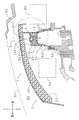
まず、本実施形態の隙間遮断構造の構成について説明する。以下に示す図においては、車両後方から前方を見た場合を基準に、方位(左右)を定義する。図1に、本実施形態の隙間遮断構造の上面図を示す。図2に、図1のII−II断面図を示す(隣接部材も配置してある)。図3に、同隙間遮断構造の透過斜視図を示す。図4に、同隙間遮断構造の分解斜視図を示す。
<First embodiment>
[Configuration of gap blocking structure]
First, the configuration of the gap blocking structure of this embodiment will be described. In the drawings shown below, the azimuth (left and right) is defined based on the case of looking forward from the rear of the vehicle. FIG. 1 shows a top view of the gap blocking structure of the present embodiment. FIG. 2 is a cross-sectional view taken along the line II-II in FIG. 1 (adjacent members are also arranged). FIG. 3 shows a transparent perspective view of the gap blocking structure. FIG. 4 shows an exploded perspective view of the gap blocking structure.
隙間遮断構造1は、図1〜図4に示すように、車両のエンジンルーム90に配置されている。車室(図略)は、エンジンルーム90の後方に配置されている。隙間遮断構造1は、エンジンカバー2と、シリンダヘッドカバー用カバー3と、遮断部材4と、を備えている。
As shown in FIGS. 1 to 4, the
エンジンカバー2は、フードパネル91の下方に配置されている。また、エンジンカバー2は、ディーゼルエンジン92を上方から覆っている。エンジンカバー2は、ボルト−ナット構造により、ディーゼルエンジン92に、脱着可能に取り付けられている。
The
具体的には、ディーゼルエンジン92上面の所定位置には、ボルト(図略)が突設されている。一方、エンジンカバー2の所定位置には、ボルトに対向して、ボルト貫通孔(図略)が形成されている。ボルトをボルト貫通孔に相対的に挿入し、ボルト先端にナット(図略)を螺着することにより、エンジンカバー2は、ディーゼルエンジン92に、取り付けられている。
Specifically, bolts (not shown) project from a predetermined position on the upper surface of the
エンジンカバー2は、カバー本体20と、吸音部材21と、を備えている。吸音部材21は、本発明の弾性部材に含まれる。カバー本体20は、ABS(アクリロニトリル、スチレン、ブタジエンの共重合体)樹脂製であって、下方に開口する浅底の矩形トレイ状を呈している。カバー本体20には、孔部200、201が形成されている。
The
吸音部材21は、ウレタン発泡体製であって、カバー本体20の下面(上底面)に層状に配置されている。吸音部材21は、発泡成形により、カバー本体20に一体に形成されている。
The
シリンダヘッドカバー用カバー3は、エンジンカバー2の下方に、所定間隔離間して配置されている。また、シリンダヘッドカバー用カバー3は、ディーゼルエンジン92のシリンダヘッドカバー920を、上方から覆っている。図5に、図2の円V内の拡大図を示す。
The cylinder
シリンダヘッドカバー用カバー3は、図3〜図5に示すように、カバー本体30と、吸音部材31と、取付部32と、ボス部33と、を備えている。カバー本体30は、PA(ポリアミド)製であって、下方に開口する浅底の細長いトレイ状を呈している。
As shown in FIGS. 3 to 5, the cylinder
取付部32は、カバー本体30上面に配置されている。取付部32は、カバー本体30と一体に形成されている。取付部32は、ホース用凹部320と、ハーネス用凹部321と、を備えている。ホース用凹部320およびハーネス用凹部321は、共に、上方に開口するC字状を呈している。ホース用凹部320には、ホース940が取り付けられている。ハーネス用凹部321には、ハーネス941が取り付けられている。ホース940、ハーネス941は、共に、本発明の保護対象部材に含まれる。
The
ボス部33は、短軸円筒状であって、カバー本体30の上面に突設されている。ボス部33の筒内空間は、シリンダヘッドカバー用カバー3を上下方向に貫通している。ボス部33は、前記エンジンカバー2の孔部200の下方に配置されている。
The
吸音部材31は、ウレタン発泡体製であって、カバー本体30の下方開口内に層状に配置されている。吸音部材31は、発泡成形により、カバー本体30に一体に形成されている。
The
遮断部材4は、シリンダヘッドカバー用カバー3のカバー本体30上面から、上方に突設されている。遮断部材4は、シリンダヘッドカバー用カバー3のカバー本体30に、一体に形成されている。遮断部材4は、ボス部33を挟んで、左右方向に延在する板状を呈している。遮断部材4は、クランク状に延在している。すなわち、遮断部材4は、前後方向に折れ曲がる湾曲部40a〜40fを備えている。また、遮断部材4は、取付部32の後方に配置されている。遮断部材4の上端は、前記エンジンカバー2の吸音部材21下面に弾接している。
The blocking member 4 protrudes upward from the upper surface of the cover
遮断部材4により、エンジンカバー2の吸音部材21下面と、シリンダヘッドカバー用カバー3のカバー本体30上面と、の間の隙間は、前方部分と後方部分とに遮断されている。遮断部材4の後方には、ターボチャージャー93が配置されている。ターボチャージャー93は、本発明の熱源に含まれる。これに対して、遮断部材4の前方には、吸気配管94が配置されている。
A gap between the lower surface of the
[作用効果]
次に、本実施形態の隙間遮断構造の作用効果について説明する。本実施形態の隙間遮断構造1のエンジンカバー2とシリンダヘッドカバー用カバー3との間の隙間には、遮断部材4が配置されている。遮断部材4は、ターボチャージャー93と、取付部32(つまりホース940およびハーネス941)と、の間に介在している。このため、ホース940およびハーネス941を、ターボチャージャー93の熱(図5に、白抜き矢印A1で模式的に示す。)から保護することができる。
[Function and effect]
Next, the function and effect of the gap blocking structure of this embodiment will be described. A blocking member 4 is disposed in a gap between the
また、遮断部材4は、シリンダヘッドカバー用カバー3に一体に形成されている。このため、遮断部材4をシリンダヘッドカバー用カバー3と別体にした場合と比較して、部品点数を少なくすることができる。
The blocking member 4 is integrally formed with the cylinder
また、エンジンカバー2は、吸音部材21を備えている。遮断部材4の上端は、吸音部材21に弾接している。このため、遮断部材4の振動を抑制することができる。したがって、例えばビビリ音のような、騒音が発生するのを抑制することができる。
The
また、遮断部材4の上端が吸音部材21に弾接しているため、遮断部材4の上端と吸音部材21との間に隙間が発生しない。したがって、遮断部材4と吸音部材21との間の隙間を介して、空気が流れるのを抑制することができる。このように、本実施形態の隙間遮断構造1によると、遮熱性が高くなる。
Further, since the upper end of the blocking member 4 is in elastic contact with the
また、本実施形態の隙間遮断構造1によると、遮断部材4を隔てて、前方には吸気配管94が、後方には車室が、それぞれ配置されている。このため、吸気配管94からの吸気騒音(図5に、白抜き矢印A2で模式的に示す。)が、車室に伝達するのを抑制することができる。
Further, according to the
また、本実施形態の隙間遮断構造1によると、遮断部材4は、ターボチャージャー93と取付部32(つまりホース940およびハーネス941)との配置方向(前後方向)に対して交差する方向(左右方向)に延在している。そして、遮断部材4には、湾曲部40a〜40fが形成されている。このため、遮断部材4が直線状の場合と比較して、より大きな弾接力で、遮断部材4の上端を吸音部材21に弾接させることができる。したがって、より確実に遮断部材4の上端から騒音が発生するのを抑制することができる。並びに、遮断部材4の上端と吸音部材21との間の遮熱性が、より高くなる。また、遮断部材4がクランク状に延在しているので、吸気配管94に対する車室の遮音性が向上する。
Further, according to the
また、湾曲部40a〜40fにより遮断部材4自体の剛性が高くなるため、遮断部材4の振動を抑制することができる。したがって、遮断部材4自体から騒音が発生するのを、さらに抑制することができる。 Further, since the rigidity of the blocking member 4 itself is increased by the curved portions 40a to 40f, the vibration of the blocking member 4 can be suppressed. Therefore, it is possible to further suppress the generation of noise from the blocking member 4 itself.
また、近年の車両においては、ショートノーズ化が進んでおり、車室のカウルが従来よりも前方(エンジンルーム90方向)に、ディーゼルエンジン92が従来よりも後方(車室方向)に、配置される傾向にある。このため、エンジンカバー2の周囲には、例えば図2に示すワイパー取付部95のように、様々な隣接部材が配置されている。したがって、エンジンカバー2を取り付ける際、現状においても上下方向にストロークを確保しにくい。仮に、遮断部材4をエンジンカバー2に一体に形成すると、エンジンカバー2を取り付ける際、さらに遮断部材4用のストロークまで確保する必要がある。このため、現状にも増して、さらに上下方向にストロークを確保しにくくなる。
Further, in recent vehicles, the short nose is progressing, and the cowl of the passenger compartment is disposed forward (in the direction of the engine room 90) and the
この点、本実施形態の隙間遮断構造1によると、遮断部材4がシリンダヘッドカバー用カバー3に一体に形成されている。このため、エンジンカバー2を取り付ける際、遮断部材4用のストロークまで確保する必要がない。したがって、エンジンカバー2の取付作業が容易になる。また、遮断部材4用のストロークを確保するために、エンジンカバー2の構造を変更する必要がない。このため、エンジンカバー2の設計の自由度が高くなる。また、エンジンカバー2の製造コストを削減することができる。
In this regard, according to the
また、エンジンカバー2の裏側には、ディーゼルエンジン92の騒音低減のため、弾性を有する吸音部材21が既設されている。本実施形態の隙間遮断構造1の場合、この吸音部材21を、本発明の隙間遮断構造1用の弾性部材と兼用している。このため、別途、本発明の隙間遮断構造1用の弾性部材を配置する場合と比較して、部品点数が少なくなる。
In addition, on the back side of the
また、遮断部材4をシリンダヘッドカバー用カバー3に一体に形成している。このため、遮断部材4をエンジンカバー2に一体に形成する場合と比較して、エンジンカバー2を敢えて耐熱性の高い材料で作製する必要がない。したがって、エンジンカバー2の製造コストを削減することができる。また、既設のシリンダヘッドカバー用カバー3は、本来、耐熱性の高い材料で作製されている。このため、既設のシリンダヘッドカバー用カバー3に小さな設計変更を施すだけで、耐熱性の高い遮断部材4を配置することができる。
Further, the blocking member 4 is formed integrally with the cylinder
また、シリンダヘッドカバー用カバー3には、取付部32が一体に形成されている。並びに、取付部32とターボチャージャー93との間には、遮断部材4が介在している。このため、より確実に、ホース940およびハーネス941をターボチャージャー93の熱から保護することができる。また、取付部32により、ホース940およびハーネス941が、ターボチャージャー93の熱の影響を受けないように、配索経路を設定することができる。また、取付部32には、ホース用凹部320と、ハーネス用凹部321と、が別々に配置されている。このため、ホース940とハーネス941とが干渉するのを抑制することができる。また、シリンダヘッドカバー用カバー3と取付部32とが別体である場合と比較して、部品点数を削減することができる。
The cylinder
また、ディーゼルエンジン92は、ガソリンエンジン(例えばオットーサイクルエンジン、ミラーサイクルエンジン、アトキンソンサイクルエンジンなど)と比較して、騒音が大きい。このため、シリンダヘッドカバー用カバー3が配置されている場合が多い。したがって、本実施形態の隙間遮断構造1をディーゼルエンジン92に用いる場合、既存のシリンダヘッドカバー用カバー3、エンジンカバー2を利用して、本実施形態の隙間遮断構造1を配置することができる。
Further, the
また、本実施形態の隙間遮断構造1によると、エンジンカバー2の取付作業と同時に、遮断部材4の上端を吸音部材21に弾接させることができる。このため、別途、遮断部材4の上端を吸音部材21に弾接させる工程が必要な場合と比較して、工程数が少なくなる。
Further, according to the
また、遮断部材4の上端の吸音部材21下面に対する埋没代L1(前出図5参照)も、エンジンカバー2の取付構造(ボルト−ナット構造)により、設定することができる。このため、車種に応じて、自在に埋没代L1を設定することができる。言い換えると、自在に弾接力を設定することができる。また、同一車種の複数の車両の埋没代L1を均一化することができる。言い換えると、隙間遮断構造1の、熱や音に対する遮断性能のばらつきを、抑制することができる。
Further, the buried margin L1 (see FIG. 5) for the lower surface of the
<参考形態>
本参考形態の隙間遮断構造と、第一実施形態の隙間遮断構造と、の相違点は、遮断部材が波状を呈している点である。また、シリンダヘッドカバー用カバーに取付部が配置されていない点である。したがって、ここでは相違点についてのみ説明する。
< Reference form>
A gap blocking mechanism according to this reference embodiment, the gap blocking mechanism according to the first embodiment, the difference is that the blocking member exhibits a wavy. Moreover, the attachment part is not arrange | positioned at the cover for cylinder head covers. Therefore, only the differences will be described here.
図6に、参考形態の隙間遮断構造の透過斜視図を示す。なお、図3と対応する部位については、同じ符号で示す。図6に示すように、遮断部材4は、左右方向に波状(サイン曲線状)に延在している。すなわち、遮断部材4の略全長に亘って、湾曲部が配置されている。また、シリンダヘッドカバー用カバー3には、ホースやハーネスを取り付けるための取付部が配置されていない。
FIG. 6 shows a transparent perspective view of the gap blocking structure of the reference embodiment. In addition, about the site | part corresponding to FIG. 3, it shows with the same code | symbol. As shown in FIG. 6, the blocking member 4 extends in a wavy shape (sine curve shape) in the left-right direction. That is, the curved portion is arranged over substantially the entire length of the blocking member 4. Further, the cylinder
本参考形態の隙間遮断構造1は、構成が共通する部分については、第一実施形態の隙間遮断構造と同様の作用効果を有する。また、本参考形態の隙間遮断構造1によると、遮断部材4が波状を呈している。このため、さらに大きな弾接力で、遮断部材4の上端をエンジンカバー2の吸音部材に弾接させることができる。したがって、より確実に遮断部材4の上端から騒音が発生するのを抑制することができる。並びに、より遮断部材4の上端と吸音部材との間の遮熱性が高くなる。また、遮断部材4が波状に延在しているので、吸気配管94に対する車室の遮音性が向上する。また、本参考形態の隙間遮断構造1によると、シリンダヘッドカバー用カバー3に取付部が形成されていない。このため、シリンダヘッドカバー用カバー3の作製が簡単になる。
<第二実施形態>
本実施形態の隙間遮断構造と、第一実施形態の隙間遮断構造と、の相違点は、遮断部材がシリンダヘッドカバー用カバーではなく、エンジンカバーに一体に形成されている点である。したがって、ここでは相違点についてのみ説明する。
< Second embodiment>
The difference between the gap blocking structure of the present embodiment and the gap blocking structure of the first embodiment is that the blocking member is formed integrally with the engine cover instead of the cylinder head cover cover. Therefore, only the differences will be described here.
図7に、本実施形態の隙間遮断構造のシリンダヘッドカバー用カバー付近の断面図を示す。なお、図5と対応する部位については、同じ符号で示す。図7に示すように、シリンダヘッドカバー用カバー3の吸音部材35は、カバー本体30の後端を介して、カバー本体30下面(裏面)から上面(表面)に回り込んでいる。吸音部材35は、本発明の弾性部材に含まれる。吸音部材35は、ウレタン発泡体製である。吸音部材35は、発泡成形により、カバー本体30に一体に形成されている。
FIG. 7 shows a cross-sectional view of the vicinity of the cylinder head cover cover of the gap blocking structure of the present embodiment. In addition, about the site | part corresponding to FIG. 5, it shows with the same code | symbol. As shown in FIG. 7, the
一方、エンジンカバー2のカバー本体20の下面からは、板状の遮断部材5が突設されている。カバー本体20は、PA製である。遮断部材5は、カバー本体20に一体に形成されている。遮断部材5の下端は、吸音部材35のうち、カバー本体30の上面に回り込んだ部分に、弾接している。
On the other hand, a plate-shaped blocking member 5 protrudes from the lower surface of the
本実施形態の隙間遮断構造1は、構成が共通する部分については、第一実施形態の隙間遮断構造と同様の作用効果を有する。エンジンカバー2の取付時のストロークを充分に確保できる場合は、本実施形態の隙間遮断構造1のように、エンジンカバー2に遮断部材5を配置してもよい。
The
また、本実施形態の隙間遮断構造1によると、エンジンカバー2の取付作業と同時に、遮断部材5の下端を吸音部材35に弾接させることができる。このため、別途、遮断部材5の下端を吸音部材35に弾接させる工程が必要な場合と比較して、工程数が少なくなる。
Further, according to the
また、遮断部材5の下端の吸音部材35上面に対する埋没代L2(前出図7参照)も、エンジンカバー2の取付構造により、設定することができる。このため、車種に応じて、自在に埋没代L2を設定することができる。言い換えると、自在に弾接力を設定することができる。また、同一車種の複数の車両の埋没代L2を均一化することができる。言い換えると、隙間遮断構造1の、熱や音に対する遮断性能のばらつきを、抑制することができる。
Further, the burying allowance L2 (see FIG. 7) with respect to the upper surface of the
<その他>
以上、本発明の隙間遮断構造の実施の形態について説明した。しかしながら、実施の形態は上記形態に特に限定されるものではない。当業者が行いうる種々の変形的形態、改良的形態で実施することも可能である。
<Others>
The embodiment of the gap blocking structure of the present invention has been described above. However, the embodiment is not particularly limited to the above embodiment. Various modifications and improvements that can be made by those skilled in the art are also possible.
例えば、上記実施形態においては、フロントエンジンタイプの車両に本発明の隙間遮断構造を用いたが、リヤエンジンタイプ(車室の後方にエンジンがあるタイプ)の車両(例えばバスなど)、ミッドシップタイプ(車室の近傍にエンジンがあるタイプ)の車両に本発明の隙間遮断構造を用いてもよい。 For example, in the above embodiment, the clearance blocking structure of the present invention is used for a front engine type vehicle, but a rear engine type (a type in which an engine is located behind the passenger compartment) vehicle (for example, a bus), a midship type ( The clearance blocking structure of the present invention may be used for a vehicle of a type in which an engine is in the vicinity of the passenger compartment.
また、エンジンカバー2、シリンダヘッドカバー用カバー3の配置方向は特に限定しない。例えば、エンジンカバー2をエンジンの前後左右などに配置してもよい。また、シリンダヘッドカバー用カバー3を、エンジンの形状、シリンダの角度に応じて、適宜傾斜させて配置してもよい。
Further, the arrangement direction of the
また、遮断部材4、5は、エンジンカバー2とシリンダヘッドカバー用カバー3との間の隙間の、左右方向全長に亘って配置しなくてもよい。保護対象部材(ホース940、ハーネス941)と熱源(ターボチャージャー93)との間に、遮断部材4、5が介在するように配置すればよい。また、上記実施形態においては、ディーゼルエンジン92に本発明の隙間遮断構造を用いたが、ガソリンエンジンに本発明の隙間遮断構造を用いてもよい。
Further, the blocking members 4 and 5 may not be disposed over the entire length in the left-right direction of the gap between the
また、エンジンカバー2の取付構造は、ボルト−ナット構造に限定しない。ディーゼルエンジン92にボルトの代わりに先端が球状のピンを、エンジンカバー2にボルト貫通孔の代わりに内部空間が球状の凹部を、それぞれ配置してもよい。そして、ピンを凹部に圧入することにより、エンジンカバー2をディーゼルエンジン92に取り付けてもよい。この場合であっても、凹部に対するピンの圧入代を調整することにより、埋没代L1、L2を自在に設定することができる。
Further, the mounting structure of the
また、上記第一実施形態、参考形態においては、エンジンカバー2のカバー本体20をABS樹脂製としたが、PP(ポリプロピレン)など他の樹脂製としてもよい。また、上記実施形態においてはシリンダヘッドカバー用カバー3のカバー本体30を、第二実施形態においてはエンジンカバー2のカバー本体20を、PA製としたが、他の樹脂製としてもよい。所望の耐熱性が確保できればよい。
In the first embodiment and the reference embodiment, the cover
また、上記実施形態においては、本発明の熱源としてターボチャージャー93を例示したが、例えばエキゾーストマニホールドなどであってもよい。熱源は、複数配置されていてもよい。
Moreover, in the said embodiment, although the
また、上記実施形態においては、本発明の保護対象部材としてホース、ハーネスを例示したが、例えば各種センサー、各種バルブなどであってもよい。保護対象部材は、複数配置されていてもよい。 Moreover, in the said embodiment, although the hose and the harness were illustrated as a protection object member of this invention, for example, various sensors, various valves, etc. may be sufficient. A plurality of members to be protected may be arranged.
また、上記実施形態においては、構成(1−1)の音源として吸気配管94を例示したが、例えばエアクリーナーなどであってもよい。音源は、複数配置されていてもよい。
Moreover, in the said embodiment, although the
1:隙間遮断構造。
2:エンジンカバー、20:カバー本体、21:吸音部材(弾性部材)、200:孔部、201:孔部。
3:シリンダヘッドカバー用カバー、30:カバー本体、31:吸音部材、32:取付部、33:ボス部、35:吸音部材(弾性部材)、320:ホース用凹部、321:ハーネス用凹部。
4:遮断部材、40a〜40f:湾曲部。
5:遮断部材。
90:エンジンルーム、91:フードパネル、92:ディーゼルエンジン、93:ターボチャージャー(熱源)、94:吸気配管、95:ワイパー取付部、920:シリンダヘッドカバー、940:ホース(保護対象部材)、941:ハーネス(保護対象部材)。
A1:矢印、A2:矢印、L1:埋没代、L2:埋没代。
1: Clearance blocking structure.
2: engine cover, 20: cover body, 21: sound absorbing member (elastic member), 200: hole, 201: hole.
3: cover for cylinder head cover, 30: cover body, 31: sound absorbing member, 32: mounting portion, 33: boss portion, 35: sound absorbing member (elastic member), 320: recess for hose, 321: recess for harness.
4: Blocking member, 40a-40f: curved part.
5: Blocking member.
90: Engine room, 91: Hood panel, 92: Diesel engine, 93: Turbocharger (heat source), 94: Intake piping, 95: Wiper mounting part, 920: Cylinder head cover, 940: Hose (member to be protected), 941: Harness (member to be protected).
A1: Arrow, A2: Arrow, L1: Buried allowance, L2: Buried allowance.
Claims (3)
該エンジンカバーの裏側に所定間隔離間して配置されるシリンダヘッドカバーの表側に配置されるシリンダヘッドカバー用カバーと、
該エンジンカバーと該シリンダヘッドカバー用カバーとの間の隙間の少なくとも一部を遮断し、該エンジンカバーおよび該シリンダヘッドカバー用カバーのうち、一方に一体に形成され、他方の有する弾性部材に該弾性部材の弾性力を利用して弾接する遮断部材と、
を備えてなり、
該遮断部材を隔てて、一方には熱源が、他方には保護対象部材が、それぞれ配置されており、
該シリンダヘッドカバー用カバーには、該保護対象部材が取り付けられる取付部が一体に形成されており、
該取付部と該熱源との間には、該遮断部材が介在している隙間遮断構造。 An engine cover,
A cylinder head cover cover disposed on the front side of the cylinder head cover disposed at a predetermined interval on the back side of the engine cover;
At least a part of a gap between the engine cover and the cylinder head cover cover is cut off, and the elastic member is formed integrally with one of the engine cover and the cylinder head cover cover, and the other elastic member A blocking member that elastically contacts using the elastic force of
With
A heat source is disposed on one side and a member to be protected is disposed on the other side, with the shielding member interposed therebetween .
The cylinder head cover cover is integrally formed with an attachment portion to which the member to be protected is attached,
A gap blocking structure in which the blocking member is interposed between the mounting portion and the heat source .
該遮断部材の少なくとも一部には、湾曲部が配置されている請求項1に記載の隙間遮断構造。 The blocking member extends in a direction intersecting the arrangement direction of the heat source and the protection target member,
The gap blocking structure according to claim 1, wherein a curved portion is disposed on at least a part of the blocking member.
前記遮断部材は、前記シリンダヘッドカバー用カバーに一体に形成されている請求項1または請求項2に記載の隙間遮断構造。 The elastic member is disposed on the back side of the engine cover,
The gap blocking structure according to claim 1, wherein the blocking member is formed integrally with the cylinder head cover cover.
Priority Applications (2)
| Application Number | Priority Date | Filing Date | Title |
|---|---|---|---|
| JP2007282737A JP4852019B2 (en) | 2007-10-31 | 2007-10-31 | Gap blocking structure |
| EP08018507A EP2055920B1 (en) | 2007-10-31 | 2008-10-22 | Gap blocking mechanism |
Applications Claiming Priority (1)
| Application Number | Priority Date | Filing Date | Title |
|---|---|---|---|
| JP2007282737A JP4852019B2 (en) | 2007-10-31 | 2007-10-31 | Gap blocking structure |
Publications (2)
| Publication Number | Publication Date |
|---|---|
| JP2009108789A JP2009108789A (en) | 2009-05-21 |
| JP4852019B2 true JP4852019B2 (en) | 2012-01-11 |
Family
ID=40139273
Family Applications (1)
| Application Number | Title | Priority Date | Filing Date |
|---|---|---|---|
| JP2007282737A Active JP4852019B2 (en) | 2007-10-31 | 2007-10-31 | Gap blocking structure |
Country Status (2)
| Country | Link |
|---|---|
| EP (1) | EP2055920B1 (en) |
| JP (1) | JP4852019B2 (en) |
Families Citing this family (3)
| Publication number | Priority date | Publication date | Assignee | Title |
|---|---|---|---|---|
| JP5654926B2 (en) * | 2011-03-30 | 2015-01-14 | 住友理工株式会社 | Engine cover and engine soundproof structure |
| JP5845231B2 (en) * | 2013-10-25 | 2016-01-20 | 本田技研工業株式会社 | Soundproof structure of internal combustion engine |
| JP6468687B2 (en) * | 2015-02-02 | 2019-02-13 | 本田技研工業株式会社 | Sound insulation structure of internal combustion engine |
Family Cites Families (9)
| Publication number | Priority date | Publication date | Assignee | Title |
|---|---|---|---|---|
| DE3464128D1 (en) * | 1983-04-08 | 1987-07-16 | Avl Verbrennungskraft Messtech | Automotive vehicle |
| JPS6360009U (en) * | 1986-10-06 | 1988-04-21 | ||
| JP2595606Y2 (en) | 1992-11-09 | 1999-05-31 | ダイハツ工業株式会社 | Heat damage prevention device for internal combustion engine |
| DE19626251A1 (en) * | 1996-06-29 | 1998-01-08 | Bosch Gmbh Robert | Air duct system |
| JPH11200881A (en) * | 1998-01-16 | 1999-07-27 | Sanwa Packing Kogyo Co Ltd | Cover device |
| JP4123573B2 (en) * | 1998-06-29 | 2008-07-23 | マツダ株式会社 | Direct injection diesel engine |
| JP2002129974A (en) * | 2000-07-27 | 2002-05-09 | Toyoda Gosei Co Ltd | Engine cover |
| US6805219B2 (en) * | 2001-07-27 | 2004-10-19 | Toyoda Gosei Co., Ltd. | Engine cover |
| JP2005264790A (en) | 2004-03-17 | 2005-09-29 | Tokai Rubber Ind Ltd | Sound insulation cover |
-
2007
- 2007-10-31 JP JP2007282737A patent/JP4852019B2/en active Active
-
2008
- 2008-10-22 EP EP08018507A patent/EP2055920B1/en active Active
Also Published As
| Publication number | Publication date |
|---|---|
| EP2055920A3 (en) | 2009-12-30 |
| EP2055920A2 (en) | 2009-05-06 |
| EP2055920B1 (en) | 2012-04-18 |
| JP2009108789A (en) | 2009-05-21 |
Similar Documents
| Publication | Publication Date | Title |
|---|---|---|
| US9394860B2 (en) | Motorcycle | |
| JP2013155666A (en) | Fuel supply device for vehicular engine | |
| JP4852019B2 (en) | Gap blocking structure | |
| JP2007176345A (en) | Fuel system for vehicle engine | |
| US11384679B2 (en) | Exhaust device and straddle-type vehicle | |
| JP4019913B2 (en) | Engine fuel system protection device | |
| JP2006322376A (en) | Protector cover of internal combustion engine | |
| JP5645130B2 (en) | Piping structure of a turbocharger for vehicles | |
| JP2015071945A (en) | Exhaust emission control device of internal combustion engine | |
| JP6303554B2 (en) | Intake device for vehicle engine | |
| JP6536668B1 (en) | engine | |
| JP2007296955A (en) | Mounting structure of exhaust heat recovery device for vehicle | |
| JP6629696B2 (en) | Internal combustion engine | |
| JP2005273511A (en) | Intake air temperature decreasing device for vehicular engine | |
| JP2013108382A (en) | Intake manifold | |
| US10190548B2 (en) | Heat shielding structure for intake system for engine of motorcycle | |
| JP2005282488A (en) | Air intake device for vehicular engine | |
| JP4370895B2 (en) | Heat shield for automobile exhaust system | |
| CN108930582B (en) | Cooling structure for internal combustion engine for vehicle | |
| JP6144485B2 (en) | Sound absorption structure for automobiles | |
| JP2018158602A (en) | Vehicle lower structure | |
| JP4707613B2 (en) | Intake device for vehicle internal combustion engine | |
| JP6680024B2 (en) | Vehicle exhaust system | |
| JP2006159994A (en) | Heat damage protection structure of cowl part of automobile | |
| JP2011247225A (en) | Intake apparatus for internal combustion engine |
Legal Events
| Date | Code | Title | Description |
|---|---|---|---|
| A621 | Written request for application examination |
Free format text: JAPANESE INTERMEDIATE CODE: A621 Effective date: 20100728 |
|
| A131 | Notification of reasons for refusal |
Free format text: JAPANESE INTERMEDIATE CODE: A131 Effective date: 20110726 |
|
| A521 | Request for written amendment filed |
Free format text: JAPANESE INTERMEDIATE CODE: A523 Effective date: 20110829 |
|
| TRDD | Decision of grant or rejection written | ||
| A01 | Written decision to grant a patent or to grant a registration (utility model) |
Free format text: JAPANESE INTERMEDIATE CODE: A01 Effective date: 20111011 |
|
| A01 | Written decision to grant a patent or to grant a registration (utility model) |
Free format text: JAPANESE INTERMEDIATE CODE: A01 |
|
| A61 | First payment of annual fees (during grant procedure) |
Free format text: JAPANESE INTERMEDIATE CODE: A61 Effective date: 20111021 |
|
| R150 | Certificate of patent or registration of utility model |
Ref document number: 4852019 Country of ref document: JP Free format text: JAPANESE INTERMEDIATE CODE: R150 Free format text: JAPANESE INTERMEDIATE CODE: R150 |
|
| FPAY | Renewal fee payment (event date is renewal date of database) |
Free format text: PAYMENT UNTIL: 20141028 Year of fee payment: 3 |
|
| S533 | Written request for registration of change of name |
Free format text: JAPANESE INTERMEDIATE CODE: R313533 |
|
| R350 | Written notification of registration of transfer |
Free format text: JAPANESE INTERMEDIATE CODE: R350 |