JP4851204B2 - Optical pickup and optical information processing apparatus - Google Patents
Optical pickup and optical information processing apparatus Download PDFInfo
- Publication number
- JP4851204B2 JP4851204B2 JP2006050043A JP2006050043A JP4851204B2 JP 4851204 B2 JP4851204 B2 JP 4851204B2 JP 2006050043 A JP2006050043 A JP 2006050043A JP 2006050043 A JP2006050043 A JP 2006050043A JP 4851204 B2 JP4851204 B2 JP 4851204B2
- Authority
- JP
- Japan
- Prior art keywords
- optical
- wavelength
- light beam
- light
- wavefront
- Prior art date
- Legal status (The legal status is an assumption and is not a legal conclusion. Google has not performed a legal analysis and makes no representation as to the accuracy of the status listed.)
- Expired - Fee Related
Links
Images


Landscapes
- Optical Head (AREA)
Description
本発明は、PMMAで形成され、環境湿度が変化しても光学機能の変化が少ないた光学素子を用いる光ピックアップおよび光情報処理装置に関するものである。 The present invention is made in PMMA, to an optical pickup and an optical information processing apparatus Ru using the optical element changes were small optical function even ambient humidity is changed.
近年の光ピックアップ、光情報処理装置は、より短波長の半導体レーザーからの光束を用いて、高密度な情報の記録および/または再生を可能としたものが開発されている。例えば、光源の発振波長λが405nm程度の青紫色半導体レーザーを光源とし、開口数(以下、NAという)が0.85の対物レンズを用いたシステムの開発が進んでいる。これは現行のDVD(NA=0.6,λ=660nm)の記録容量4.7GBに対して、例えばNA=0.85,λ=405nmでは、25GB程度の情報の記録が可能となる。 In recent years, optical pickups and optical information processing apparatuses have been developed that can record and / or reproduce high-density information using a light beam from a semiconductor laser having a shorter wavelength. For example, a system using a blue-violet semiconductor laser having an oscillation wavelength λ of about 405 nm as a light source and an objective lens having a numerical aperture (hereinafter referred to as NA) of 0.85 has been developed. For example, when NA = 0.85, λ = 405 nm, information of about 25 GB can be recorded with respect to the recording capacity of 4.7 GB of the current DVD (NA = 0.6, λ = 660 nm).
また、そのような高密度な情報の記録および/または再生を行える光ピックアップであっても、従来から大量に供給されたCD,DVDに対しても情報の記録および/または再生を確保する必要がある。3つの異なる記録媒体を共用してそれぞれ1つの光ピックアップを用いて記録あるいは再生するものとしては、例えば1つの回折面を用いて、波長λ1の光束による次世代DVD、波長λ2の光束による従来のDVD、および波長λ3の光束によるCDのそれぞれについて、互換性のあるようにしたものが提案されている。そのため波長選択性を備えた回折構造を設けることも行われている(特許文献1,2参照)。
Further, even with an optical pickup capable of recording and / or reproducing such high-density information, it is necessary to ensure the recording and / or reproducing of information even with respect to CDs and DVDs that have been supplied in large quantities. is there. For recording and reproducing using one optical pickup in common with three different recording media, for example, using a single diffractive surface, a next-generation DVD using a light beam with a wavelength λ1 and a conventional light beam using a wavelength λ2 A DVD and a CD with a light beam having a wavelength of λ3 that are compatible with each other have been proposed. Therefore, a diffraction structure having wavelength selectivity is also provided (see
さらに、前記のような回折素子は軽量化のため樹脂で形成されていることが望ましい。金型を用いて成形することにより、均一な形状の製品を迅速に製造することができるため、大量生産に適しているといえる。
しかしながら、このような樹脂素材の光学素子は、ガラスと比較して、温度や湿度の変化をうけて変形しやすく、この樹脂素材の温度,湿度変化による変形に起因した収差の変動が、短波長化と対物レンズの高NA化において顕著になる。したがって、従来の光ピックアップ光学系ではそれほど問題にならなかった、環境湿度の変動も、光源の短波長化と対物レンズの高NA化において収差の変動に伴い波面劣化が大きくなり無視できない量となるという問題があった。 However, such an optical element made of a resin material is more likely to be deformed by changes in temperature and humidity than glass, and fluctuations in aberration due to deformation due to changes in the temperature and humidity of this resin material are short wavelength. It becomes remarkable in increasing the NA of the objective lens and the objective lens. Therefore, the fluctuation of the environmental humidity, which has not been a problem with the conventional optical pickup optical system, is an amount that cannot be ignored because the wavefront deterioration increases with the fluctuation of the aberration when the wavelength of the light source is shortened and the NA of the objective lens is increased. There was a problem.
本発明は、前記従来技術の問題を解決することに指向するものであり、環境湿度が生じても、変形を低減した波面精度の良い樹脂製の回折光学素子を実現した光学素子とこれを用いる光ピックアップおよび光情報処理装置を提供することを目的とする。 The present invention is directed to solving the problems of the prior art, and uses an optical element that realizes a resin-made diffractive optical element with reduced wavefront accuracy with reduced deformation even when environmental humidity occurs. An object is to provide an optical pickup and an optical information processing apparatus.
前記の目的を達成するために、本発明に係る請求項1に記載した光ピックアップは、基板厚の異なる2種類の光記録媒体に情報の記録,再生,消去のいずれか1以上を行う光ピックアップにおいて、波長の異なる第1,第2の光源と、第1の光記録媒体の記録面上に光束を集光する前記第1の光源波長で最適化した対物レンズと、前記第2の光源からの光束が第2の光記録媒体の基板を透過する際に生じる収差を、補正する機能を持つ光学素子と、を有する。
該光学素子は、PMMAを材料として構成され、光軸に対して垂直方向の面を持ち、光束が通過する光線有効径内において前記光軸と同軸円形の回折領域と、その外側の平坦部との2つの領域に分割されている。
前記回折領域は、前記第1の光源波長の光線の光線有効径内に、前記垂直方向の面上で断面が凹凸形状となる1以上の回折構造を有し、前記第1の光源波長の光束をそのまま透過させるとともに、前記第2の光源波長の光束を、光記録媒体の基板厚の違いおよび波長の違いより生じる球面収差を補正するように回折させる。
そして、前記PMMAの吸湿による「平坦部での形状変化」が、前記同心円の円周方向に沿って均一化されるように「前記光軸と同軸の円形」もしくは「前記円形に近似した多角形状の外形形状」を有する板状であり、第1の光源波長の光線有効径内における「第1の光源波長の透過波面収差」が0.02λrms以下である。
このように、光学素子の外形形状を「光軸と同軸の円形もしくは前記円形に近似した多角形状」とすることにより、光学素子を構成するPMMAの「吸湿の影響」による「うねり等の形状変化」が同心円の円周方向に沿って均一化される。
In order to achieve the above object, an optical pickup according to
The optical element is made of PMMA, has a plane perpendicular to the optical axis, has a circular diffraction area coaxial with the optical axis within the effective beam diameter through which the light beam passes, and an outer flat portion. Are divided into two regions.
The diffractive region has one or more diffractive structures whose cross-section is uneven on the surface in the vertical direction within the effective diameter of the light beam having the first light source wavelength, and the light beam having the first light source wavelength. Is transmitted as it is, and the light beam having the second light source wavelength is diffracted so as to correct the spherical aberration caused by the difference in the substrate thickness and the wavelength of the optical recording medium.
Then, the “shape change in the flat portion” due to the moisture absorption of the PMMA is made uniform along the circumferential direction of the concentric circle, or “a circle that is coaxial with the optical axis” or “a polygon shape that approximates the circle” The “transmission wavefront aberration of the first light source wavelength” within the effective beam diameter of the first light source wavelength is 0.02λrms or less.
In this way, by changing the outer shape of the optical element to “a circular shape coaxial with the optical axis or a polygonal shape approximating the circular shape”, the “shape change such as undulation” due to the “influence of moisture absorption” of the PMMA constituting the optical element. Is made uniform along the circumferential direction of the concentric circles.
また、請求項2および3に記載した光ピックアップは、光学素子の回折構造の断面を矩形形状としたこと、回折構造の断面を階段形状としたことによって、小型,軽量化して球面収差を補正でき、環境湿度が変化しても、うねり等の変形を低減した波面精度の良い光学素子を得ることができる。
In addition, the optical pickup according to
上記のように、請求項1〜3に記載した光ピックアップは、基板厚の異なる2種類の光記録媒体に情報の記録,再生,消去のいずれか1以上を行う光ピックアップであって、光学素子に有する回折構造からの回折光により第2の光源からの光束が第2の光記録媒体の基板を透過する際に生じる収差を補正することによって、2種類の異なる基板厚、異なる光源で発生する波面収差を補正でき、小型で軽量化した高精度な光ピックアップを提供できる。 As described above, the optical pickup according to claim 1 to 3, substrate thickness different two kinds of optical recording medium for recording information, reproducing, an optical pickup for any one or more of the erase light Science Occurs with two different substrate thicknesses and different light sources by correcting the aberration that occurs when the light beam from the second light source passes through the substrate of the second optical recording medium by the diffracted light from the diffractive structure of the element. Therefore, it is possible to provide a highly accurate optical pickup that is small and lightweight.
請求項4に記載した光情報処理装置は、光記録媒体の記録面に光束を照射して情報の記録,再生,消去のいずれか1以上を行う光情報処理装置において、請求項1〜3のいずれか1項に記載の光ピックアップを備えたことによって、2種類の異なる基板厚、光源で発生する波面収差を補正でき、高精度な光情報処理装置を提供できる。
The optical information processing apparatus according to
本発明によれば、収差補正素子を小型,軽量化して球面収差の補正を可能とし、また収差補正素子の樹脂(PMMA)の吸湿による形状変化を均一化し、環境湿度変化に対応して、うねり等の変形を低減した波面精度の良い光学素子とこれを用いる光ピックアップおよび光情報処理装置を提供できるという効果を奏する。 According to the present invention, it is possible to correct spherical aberration by reducing the size and weight of the aberration correction element, and uniformizing the shape change due to moisture absorption of the resin (PMMA) of the aberration correction element, and responding to changes in environmental humidity. An optical element with improved wavefront accuracy with reduced deformation and the like, an optical pickup using the optical element, and an optical information processing apparatus can be provided.
以下、図面を参照して本発明における実施の形態を詳細に説明する。 Hereinafter, embodiments of the present invention will be described in detail with reference to the drawings.
図1は本発明の実施の形態1の光ピックアップの概略構成を示した図である。図1に示すように、単一の対物レンズ106で、異なる波長の複数の光源を用いて、基板厚の異なる光記憶媒体を異なる有効瞳半径で情報の記録または再生を行う互換型の光ピックアップである。
FIG. 1 is a diagram showing a schematic configuration of an optical pickup according to
本例では、2種類の異なる基板厚を有する光記録媒体に情報の記録あるいは再生を行う場合を例としている。第1,第2の光記録媒体107,137の基板厚は、それぞれ0.1mm,0.6mm、第1,第2の開口数は、それぞれNA0.85,NA0.65、第1,第2の光源波長は、それぞれ405nm(青紫色領域)、660nm(赤色領域)である。 In this example , the case where information is recorded on or reproduced from an optical recording medium having two different substrate thicknesses is taken as an example. The substrate thicknesses of the first and second optical recording media 107 and 137 are 0.1 mm and 0.6 mm, respectively, and the first and second numerical apertures are NA 0.85 and NA 0.65, respectively. The light source wavelengths are 405 nm (blue-violet region) and 660 nm (red region), respectively.
本例における光ピックアップは、図1に示すように第1の光記録媒体107に対して、半導体レーザー101,コリメートレンズ102,プリズム104,1/4波長板105,対物レンズ106,偏光ビームスプリッタ103,検出レンズ108,開口制限素子109,収差補正素子501,受光素子110より構成される。
As shown in FIG. 1, the optical pickup in this example has a semiconductor laser 101, a collimator lens 102, a prism 104, a quarter wavelength plate 105, an objective lens 106, and a polarization beam splitter 103 with respect to the first optical recording medium 107. , Detection lens 108, aperture limiting element 109,
第1の光源である半導体レーザー101の中心波長は405nmであり、対物レンズ106の開口数NAは0.85、第1の光記録媒体107の基板厚は0.1mmとする。半導体レーザー101の出射光は、コリメートレンズ102により略平行光にされる。コリメートレンズ102を通過した光束は偏光ビームスプリッタ103に入射し、プリズム104より偏向される。そして、1/4波長板105,開口制限素子109,収差補正素子501,対物レンズ106を介して第1の光記録媒体107に集光されることにより、情報の記録,再生が行われる。
The center wavelength of the semiconductor laser 101 as the first light source is 405 nm, the numerical aperture NA of the objective lens 106 is 0.85, and the substrate thickness of the first optical recording medium 107 is 0.1 mm. The light emitted from the semiconductor laser 101 is made into substantially parallel light by the collimator lens 102. The light beam that has passed through the collimator lens 102 enters the polarization beam splitter 103 and is deflected by the prism 104. Information is recorded and reproduced by being focused on the first optical recording medium 107 via the quarter-wave plate 105, the aperture limiting element 109, the
また、第1の光記録媒体107からの反射光は、対物レンズ106,1/4波長板105を通過した後、偏光ビームスプリッタ103により入射光と分離して偏向され、検出レンズ108により受光素子110上に導かれ、再生信号,フォーカス誤差信号,トラック誤差信号が検出される。 Reflected light from the first optical recording medium 107 passes through the objective lens 106 and the quarter-wave plate 105, is then separated from the incident light by the polarization beam splitter 103, and deflected, and is detected by the detection lens 108. 110, the reproduction signal, the focus error signal, and the track error signal are detected.
同様に、第2の光記録媒体137に対して、中心波長が660nmの半導体レーザー130aから出射した光束は、発散角変換レンズ132,波長選択性ビームスプリッタ133を経て、プリズム104より偏向される。そして、1/4波長板105,開口制限素子109,収差補正素子501,対物レンズ106を介して、第2の光記録媒体137に集光される。この第2の光記録媒体137の基板厚は0.6mmであり、対物レンズの開口数NAは0.65である。開口数NAの切り替えは、波長選択性の開口制限素子109を用いる。
Similarly, the light beam emitted from the semiconductor laser 130 a having a center wavelength of 660 nm with respect to the second optical recording medium 137 is deflected by the prism 104 through the divergence angle conversion lens 132 and the wavelength selective beam splitter 133. Then, the light is condensed on the second optical recording medium 137 through the quarter-wave plate 105, the aperture limiting element 109, the
また、第2の光記録媒体137からの反射光は対物レンズ106,1/4波長板105を通過した後、波長選択性ビームスプリッタ133により偏向され、ホログラム素子130bにより入射光と分離して受光素子130c上に導かれ、再生信号,フォーカス誤差信号,トラック誤差信号が検出される。 Reflected light from the second optical recording medium 137 passes through the objective lens 106 and the quarter-wave plate 105 and is then deflected by the wavelength-selective beam splitter 133 and separated from incident light by the hologram element 130b and received. Guided on the element 130c, a reproduction signal, a focus error signal, and a track error signal are detected.
ここで、対物レンズ106は厚さ0.1mmの第1の光記録媒体107を高精度に記録,再生できるように設計されている。設計波長は405nmであり、405nmでは波面収差0.01λrms以下と十分小さくなるように、設計されている。 Here, the objective lens 106 is designed to record and reproduce the first optical recording medium 107 having a thickness of 0.1 mm with high accuracy. The design wavelength is 405 nm, and it is designed so that the wavefront aberration becomes 0.01 λrms or less sufficiently at 405 nm.
また、対物レンズ106は両面非球面形状であり、面の頂点を原点とし、光軸方向をX軸とした直交座標系において、rを近軸曲率半径、κを円錐形数、A,B,C,D,E,F,G,H,J,・・・・・を非球面係数とするとき、面の光軸方向の距離xと半径Rの関係より、非球面形状は(数1)、 The objective lens 106 has an aspherical shape on both sides, and in a rectangular coordinate system with the vertex of the surface as the origin and the optical axis direction as the X axis, r is the paraxial radius of curvature, κ is the number of cones, A, B, When C, D, E, F, G, H, J,. ,

図2は本例における収差補正素子を説明するための断面図、図3は上面図、図4は4段の階段状回折構造の拡大図である。 2 is a cross-sectional view for explaining the aberration correcting element in this example , FIG. 3 is a top view, and FIG. 4 is an enlarged view of a four-step staircase diffraction structure.
収差補正素子501は、中心波長が660nmの半導体レーザー130aから出射した光束が、光記録媒体の基板厚さの違いと、波長の違いにより発生する球面収差を補正するための互換素子である。
The
図3に示すように、収差補正素子501は、波長405nmの光線有効径502c内に、回折構造が形成されている円形中央の回折領域502aと、その周辺領域の平坦部502bとを有する。回折領域502aは、波長405nmの光束をそのまま透過させ、波長660nmの光束を光記録媒体の基板厚の違いおよび波長の違いより生じる球面収差を補正するように回折させる。
As shown in FIG. 3, the
そのため、回折領域502aには溝が形成されており、回折領域502aが波長660nmの光束の有効径に相当する。波長660nmの光束の有効瞳半径は1.74mmである。一方、周辺領域の平坦部502bは、波長405nm、波長660nmの光束をそのまま透過させる。
Therefore, a groove is formed in the
また、収差補正素子501の回折領域502aの断面は図2に示されるように同心円状に形成された複数の輪帯状凸部からなり、各輪帯状凸部は4つの段を有する。ここでは、図4に示すように、段数とは、最下段も含めて数えている。また、輪帯状凸部のピッチは、この回折構造がレンズ効果を有するように内側から外側に向かって徐々に狭くなっている。ピッチ502dの最小値は11μm、輪帯数は68である。輪帯数とは、回折構造の1周期(ピッチ502d)の数である。
The cross section of the
さらに、収差補正素子501の回折構造の溝深さおよび各段の高さについて図4を用い
て説明する。回折光学系では、入射光すべてのエネルギーが出射光に変換されるのではな
く、回折効率と呼ばれる効率でしか変換されない。図4の点線に示すような鋸歯状のキノ
フォーム形状は、ある波長でブレーズ化されると、その波長での回折効率は薄型近似の場
合、理論的には100%である。本例では、2波長のうち、波長405nmの光束に対しては透過光、波長660nmの光束に対しては回折光として使用し、図4に示すような階段近似した形状とする。また、階段形状にすることで、理想的なキノフォーム形状を製作するよりも容易となる。なお、回折構造は図4の点線に示すような鋸歯状のキノフォーム形状でも良い。
Further, the groove depth and height of each step of the diffraction structure of the
図4において鋸歯状の回折構造の溝深さをDとすると、0次光,1次光の最大の回折効率となる溝深さDの位相差は(表2)に示すようになる。 In FIG. 4, assuming that the groove depth of the sawtooth diffractive structure is D, the phase difference between the groove depths D that gives the maximum diffraction efficiency of the zero-order light and the first-order light is as shown in (Table 2).
また、収差補正素子501の材料としてはポリメチルメタクリレート(以下、PMMAという)を用いる。PMMAは、高い透明性、耐候性を有し、特に射出成形に適合する強みがあるため光学部品に最も広く使用されている樹脂の1つである。
Further, polymethyl methacrylate (hereinafter referred to as PMMA) is used as the material of the
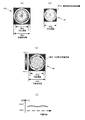
図5にPMMAの分散特性を示す。図5の分散特性から、波長405nmの0次光と波長660nmの1次光の回折効率をスカラー計算させたものが図6の透過率−溝深さの関係を示す図である。階段形状の回折構造の溝深さDが、4.8μm辺りで、波長405nmの0次光、波長660nmの1次光の効率が高く、それぞれ100%と70%となる。このことから本参考例では収差補正素子501の回折構造の溝深さDを4.8μmに設定した。
FIG. 5 shows the dispersion characteristics of PMMA. FIG. 6 is a diagram showing the relationship between the transmittance and the groove depth in FIG. 6 in which the diffraction efficiency of the zero-order light with a wavelength of 405 nm and the first-order light with a wavelength of 660 nm is calculated from the dispersion characteristics of FIG. When the groove depth D of the staircase-shaped diffractive structure is around 4.8 μm, the efficiency of the zero-order light with a wavelength of 405 nm and the primary light with a wavelength of 660 nm is high, which are 100% and 70%, respectively. Therefore, in this reference example , the groove depth D of the diffractive structure of the
また、図2に示す平坦部502bの高さは、溝の最下段に対して波長の整数倍になるように設定する。本参考例では、波長の2倍の位相差に相当する3.2μmに設定した。この平坦部502bの領域を透過した光束は、波長660nmの光束に対しては有効径外となるため、スポット形成には不要光となる。そのため図1に示したように波長選択性の開口制限素子109により、波長660nmの光束は遮断し、波長405nmの光束のみ透過する誘電体多層膜を用いる。
Further, the height of the
なお、前述の開口制限素子109は使用しなくても良い。これは、高NA対物レンズ106の場合、設計波長405nm以外の光束に対する周辺領域の光束は、収差発生量が大きく、スポット形成には影響しないためである。 The aperture limiting element 109 described above may not be used. This is because in the case of the high NA objective lens 106, the light flux in the peripheral region with respect to the light flux other than the design wavelength of 405 nm has a large aberration generation amount and does not affect the spot formation.
次に、本例における収差補正素子の外形形状について、詳細に説明する。図3に示すように、収差補正素子501の外形の形状は、回折領域502aと平坦部502bとの境界と同様の円形状とする。なお、円形状とは、円形に近似した多角形を含み、例えば図7に示すような8角形においても、同様の効果が得られる。
Next, the outer shape of the aberration correction element in this example will be described in detail. As shown in FIG. 3, the outer shape of the
本例で用いているPMMA等の樹脂は、射出成形ができる等の強みがあるため光学部品に最も広く使用され、大量生産しやすいという特徴があるが、一方で吸湿性が弱点として挙げられる。これによる影響は屈折率や透過率といった光学特性を変動させるだけでなく、形状変形としても現れる。 Resin such as PMMA used in this example has the advantage that it can be injection-molded, so that it is most widely used in optical parts and is easily mass-produced. However, it has a weak hygroscopicity. This influence not only fluctuates optical characteristics such as refractive index and transmittance, but also appears as shape deformation.
図8は従来例の収差補正素子を示す上面図である。図8に示す従来の収差補正素子511の外形形状は、四角形状であり回折領域512aと平坦部512bとの境界とは異なり円形状ではない。
FIG. 8 is a top view showing a conventional aberration correction element. The outer shape of the conventional aberration correction element 511 shown in FIG. 8 is a quadrangular shape, and is not circular, unlike the boundary between the
図9(a)〜(d)は図8に示した従来の収差補正素子511の波長405nmの透過波面形状を示す図である。図9(a)は光線有効径内512cにおける透過波面を測定した結果の波面形状を示す図である。図9(b),(c)は図9(a)の波面形状を領域に分割して波面測定した結果を示す図である。図9(b)は回折領域の透過波面512gの形状、図9(c)は光線有効径512c内と回折領域512aの間である平坦部の透過波面512fの形状を示す図である。
9A to 9D are diagrams showing the transmitted wavefront shape of the conventional aberration correction element 511 shown in FIG. 8 having a wavelength of 405 nm. FIG. 9A is a diagram showing the wavefront shape as a result of measuring the transmitted wavefront within the
各波面の形状をもとに波面収差を計算したところ、図9(a)の光線有効径512c内近傍の波面形状はPV値が0.5λ、波面収差0.1λrmsと波面精度が非常に悪い。通常、光学部品の波面収差は0.02λrms以下であることが望ましい。また、図9(b)の回折領域512a内の波面収差は、0.02λrmsとなり良好な波面精度であるのに対して、図9(c)の平坦部の透過波面512fの波面収差は0.13λrmsと大きく、光線有効径512c内の波面精度が悪い原因は、平坦部にあることがわかる。
When wavefront aberration is calculated based on the shape of each wavefront, the wavefront shape in the vicinity of the
図9(d)は平坦部の波面形状を円周方向に沿って、プロットしたものである。平坦部は収差補正素子511の四角の形状に沿って、うねりが発生しており波面劣化の要因となっていると考えられる。 FIG. 9D is a plot of the wavefront shape of the flat portion along the circumferential direction. It is considered that the flat portion is wavy along the square shape of the aberration correction element 511 and is a factor of wavefront deterioration.
このうねりの要因は、回折領域と平坦部との境界は、外形の四角形の辺から近いところ512dと遠いところ512eが存在し、近いところ512dと遠いところ512eではPMMAの吸湿に差異がある。この吸湿の差異が変形の差異となり、うねりが発生していると考えられる。 The cause of this undulation is that the boundary between the diffraction region and the flat part has 512d and far 512e near the side of the outer shape of the rectangle, and there is a difference in the moisture absorption of PMMA between 512d and far 512e. This difference in moisture absorption becomes a difference in deformation, which is considered to cause undulation.
図10(a)〜(d)に本例の収差補正素子501の波長405nmの透過波面形状を示す図である。図10(a)は光線有効径502c内における透過波面を測定した結果の波面形状を示す図である。図10(b),(c)は図10(a)の波面形状を領域に分割して波面測定した結果を示す図である。図10(b)は回折領域の透過波面502gの形状、図10(c)は光線有効径502c内と回折領域502aの間である平坦部の透過波面502fの形状を示す図である。
FIGS. 10A to 10D are diagrams showing the transmitted wavefront shape of the
また、図10(d)は平坦部の波面形状を円周方向に沿って、プロットしたものである。図10(a)の光線有効径502c内近傍の波面形状より波面収差を計算するとPV値が0.1λ、波面収差0.02λrms、図10(b)の回折領域502a内の波面収差は、0.015λrms、図10(c)の平坦部の透過波面502fの波面収差は0.017λrmsであり、周辺部のうねりはなく良好な波面精度である。
FIG. 10D is a plot of the wavefront shape of the flat portion along the circumferential direction. When the wavefront aberration is calculated from the wavefront shape in the vicinity of the
このように、収差補正素子501の外形形状を、回折領域と平坦部との境界と同様の円形状にすることで、PMMAの吸湿による形状の変化が均一化され、うねりを低減することができる。
In this way, by making the outer shape of the
以上のことから、本例の収差補正素子501は、吸湿性を有する樹脂を材料として用いた場合でも、そりやうねりを低減した収差補正素子501の構造であるため、1つの対物レンズで、2種類の異なる基板厚,光源で発生する波面収差を補正することができ、高精度な光ピックアップを提供することができる。
From the above, the
図11は、光ピックアップ参考例の概略構成を示した図である。
ここで、前記参考例を示す図1において説明した構成部材に対応し同等の機能を有するものには同一の符号を付して示す。図11に示すように異なる波長の第1,第2,第3の光源を有し、3種類の異なる光記録媒体を、収差補正素子521を用いて記録または再生を行う互換型の光ピックアップである。
FIG. 11 is a diagram illustrating a schematic configuration of an optical pickup reference example .
Here, components having the same functions corresponding to the components described in FIG. 1 showing the reference example are denoted by the same reference numerals. As shown in FIG. 11, a compatible optical pickup that has first, second, and third light sources having different wavelengths and records or reproduces three types of optical recording media using an
本参考例における第1,第2の光源に対する光ピックアップの構成は、前記実施の形態のものと同様であるため、その重複する説明は省略する。赤外領域の第3の光源において、中心波長λ3が780nmの半導体レーザー140aから出射した光束は、発散角変換レンズ142,波長選択性ビームスプリッタ143を経て、プリズム104より偏向される。そして、1/4波長板105,収差補正素子521,対物レンズ106を介して、第3の光記録媒体147に集光される。第3の光記録媒体147の基板厚は1.2mmであり、対物レンズ106の開口数NAは0.4である。第3の光記録媒体147からの反射光は対物レンズ106,収差補正素子521,1/4波長板105を通過した後、波長選択性ビームスプリッタ143により入射光と分離して偏向され、ホログラム素子140bにより受光素子140c上に導かれ、再生信号,フォーカス誤差信号,トラック誤差信号が検出される。
Since the configuration of the optical pickup for the first and second light sources in this reference example is the same as that of the above-described embodiment , the overlapping description is omitted. In the third light source in the infrared region, the light beam emitted from the semiconductor laser 140a having the center wavelength λ3 of 780 nm is deflected by the prism 104 via the divergence angle conversion lens 142 and the wavelength selective beam splitter 143. Then, the light is condensed on the third optical recording medium 147 through the quarter-wave plate 105, the
図12は本参考例における収差補正素子を説明するための断面図、図13は下面図、図14は2段の階段状回折構造の拡大図である。 FIG. 12 is a cross-sectional view for explaining the aberration correction element in the present reference example , FIG. 13 is a bottom view, and FIG. 14 is an enlarged view of a two-step staircase diffraction structure.
収差補正素子521は、中心波長が660nmの半導体レーザー130aから出射した光束と、中心波長が780nmの半導体レーザー140aから出射した光束が、光記録媒体の基板厚さの違いと、波長の違いにより発生する球面収差を補正するための互換素子である。
The
図12に示すように、収差補正素子521は、表面と裏面に回折構造が形成されている。この表面に形成された回折構造は参考例で説明した収差補正素子501と同様の構造が形成されており、上面図は図3で示した。
As shown in FIG. 12, the
収差補正素子521の表面には、収差補正素子501と同様に波長405nmの光線有効径502c内に、回折構造が形成されている円形中央の回折領域502aと、その周辺領域の平坦部502bとを有する。回折領域502aは、波長405nm、波長780nmの光束をそのまま透過させ、波長660nmの光束を、光記録媒体の基板厚の違いと、波長の違いより生じる球面収差を補正するように回折させる。
On the surface of the
そのため、回折領域502aには溝が形成されており、回折領域502aが波長660nmの光束の有効径に相当する。波長660nmの光束の有効瞳半径は1.74mmである。一方、周辺領域の平坦部502bは、波長405nm、波長660nm、波長780nmの光束をそのまま透過させる。
Therefore, a groove is formed in the
収差補正素子521の裏面の構造を図13に示す。波長405nmの光線有効径522c内に、回折構造が形成されている円形中央の回折領域522aと、その周辺領域の平坦部522bとを有する。回折領域522aは、波長405nm、波長660nmの光束をそのまま透過させ、波長780nmの光束を、光記録媒体の基板厚の違いと、波長の違いより生じる球面収差を補正するように、回折させる。
The structure of the back surface of the
そのため、回折領域522aには溝が形成されており、回折領域522aが波長780nmの光束の有効径に相当する。波長780nmの光束の有効瞳半径は1.34mmである。一方、周辺領域の平坦部522bは、波長405nm、波長660nm、波長780nmの光束をそのまま透過させる。
Therefore, a groove is formed in the
収差補正素子521の表面は、収差補正素子501と同様に、同心円状に形成された複数の輪帯状凸部からなり、各輪帯状凸部は4つの段を有する。輪帯状凸部のピッチは、この回折構造がレンズ効果を有するように内側から外側に向かって徐々に狭くなっている。最小ピッチは11μm,輪帯数は68である。
Similar to the
同様に、収差補正素子521の裏面は、同心円状に形成された複数の輪帯状凸部からなるが、各輪帯状凸部は2つの段を有する。輪帯状凸部のピッチは、この回折構造がレンズ効果を有するように内側から外側に向かって徐々に狭くなっている。最小ピッチは12μm,輪帯数は57である。
Similarly, the back surface of the
次に、収差補正素子521の表面の溝深さについて説明する。溝深さは参考例の収差補正素子501と同じである。図15に、PMMAを用いた場合の波長405nmの0次光、波長660nmの1次光、波長780nmの0次光の回折効率をスカラー計算した結果を示す。参考例と同様、回折構造の溝深さDが、4.8μm辺りで、波長405nmの0次光,波長660nmの1次光,波長780nmの0次光の効率が高く、それぞれ100%,70%,100%となる。本実施の形態1の収差補正素子521表面の回折構造の溝深さDは、4.8μmに設定した。
Next, the groove depth on the surface of the
また、収差補正素子521の裏面の溝深さについて説明する。図14において鋸歯状の回折構造の溝深さをDとすると、0次光、1次光の最大の回折効率となる溝深さの位相差は(表3)に示すようになる。
The groove depth on the back surface of the
PMMAを用いた場合の波長405nmの0次光,波長660nmの0次光,波長780nmの1次光の回折効率をスカラー計算させたのが図16である。回折構造の溝深さDが、4.0μm辺りで、波長405nmの0次光,波長660nmの1次光,波長780nmの0次光の効率が高く、それぞれ100%,100%,40%となる。本実施の形態1の収差補正素子521の回折構造の溝深さDは、4.0μmに設定した。
FIG. 16 shows the scalar calculation of the diffraction efficiencies of the 0th-order light with a wavelength of 405 nm, the 0th-order light with a wavelength of 660 nm, and the 1st-order light with a wavelength of 780 nm when PMMA is used. When the groove depth D of the diffractive structure is around 4.0 μm, the efficiency of the 0th-order light with a wavelength of 405 nm, the 1st-order light with a wavelength of 660 nm, and the 0th-order light with a wavelength of 780 nm are high, and are 100%, 100%, and 40%, respectively. Become. The groove depth D of the diffractive structure of the
また、収差補正素子521の表面の平坦部502bの高さは、参考例と同様3.2μmに設定した。そして、収差補正素子521の裏面の平坦部522bの高さは、回折構造の溝深さDと同様4μmに設定した。平坦部522bを透過した波長660nm,波長405nmの光束に対しては、回折領域と同位相を有する透過光となる。
Further, the height of the
次に、本実施の形態1における収差補正素子の外形形状について、詳細に説明する。ここでは、収差補正素子521の裏面側であるが図13に示すように、収差補正素子521の外形の形状は、回折領域と平坦部との境界と同様の円形状とする。
Next, the outer shape of the aberration correction element in the first embodiment will be described in detail. Here, although it is the back side of the
図17は従来例の収差補正素子531を示す図で、図17示すように収差補正素子531の外形形状は四角形状であり回折領域532aと平坦部532bとの境界とは異なり円形状ではない。また、図18(a)〜(d)は図17に示した従来の収差補正素子531の波長405nmの透過波面形状を示す図である。図18(a)は光線有効径内532cにおける透過波面を測定した結果の波面形状を示す図である。図18(b),(c)は図18(a)の波面形状を領域に分割して波面測定した結果を示す図である。図18(b),(c)は図18(a)の結果を領域に分割して波面測定結果を示した図である。図18(b)は回折領域の透過波面532gの形状、図18(c)は光線有効径532c内と回折領域532aの間である平坦部の透過波面532fの形状を示す図である。
FIG. 17 is a diagram showing a conventional aberration correction element 531. As shown in FIG. 17, the outer shape of the aberration correction element 531 is a quadrangle, and the boundary between the
各波面の形状をもとに波面収差を計算したところ、図18(a)の光線有効径532c内近傍の波面形状はPV値が0.6λ、波面収差0.09λrmsと波面精度が非常に悪い。通常、光学部品の波面収差は0.02λrms以下であることが望ましい。また、図18(b)の回折領域532a内の波面収差は、0.019λrms良好な波面精度であるのに対して、図18(c)の平坦部の透過波面532fの波面収差は0.093λrmsと大きく、光線有効径532c内の波面精度が悪い原因は、平坦部にあることがわかる。
When wavefront aberration is calculated based on the shape of each wavefront, the wavefront shape in the vicinity of the
図18(d)は平坦部の波面形状を円周方向に沿って、プロットしたものである。平坦部は収差補正素子531の四角の形状に沿って、うねりが発生しており波面劣化の要因となっていると考えられる。 FIG. 18D is a plot of the wavefront shape of the flat portion along the circumferential direction. It is considered that the flat portion is wavy along the square shape of the aberration correction element 531 and causes wavefront deterioration.
このうねりの要因は、回折領域と平坦部との境界は、外形の四角形の辺から近いところ532dと遠いところ532eが存在し、近いところ532dと遠いところ532eではPMMAの吸湿に差異がある。この吸湿の差異が変形の差異となり、うねりが発生していると考えられる。 The cause of this undulation is that the boundary between the diffraction region and the flat portion includes a portion 532d and a portion 532e far from the sides of the outer shape of the quadrangle, and there is a difference in the moisture absorption of PMMA between the portion 532d and the portion 532e far from the side. This difference in moisture absorption becomes a difference in deformation, which is considered to cause undulation.
図19(a)〜(d)に本参考例の収差補正素子521の波長405nmの透過波面形状を示す図である。図19(a)は光線有効径522c内における透過波面を測定した結果の波面形状を示す図である。図19(b),(c)は図19(a)の波面形状を領域に分割して波面測定した結果を示す図である。図19(b)は回折領域の透過波面522gの形状、図19(c)は光線有効径522c内と回折領域522aの間である平坦部の透過波面522fの形状を示す図である。
FIGS. 19A to 19D are diagrams showing the transmitted wavefront shape of the wavelength 405 nm of the
また、図19(d)は平坦部の波面形状を円周方向に沿って、プロットしたものである。図19(a)の光線有効径522c内近傍の波面形状より波面収差を計算するとPV値が0.15λ、波面収差0.02λrms、図19(b)の回折領域522a内の波面収差は、0.015λrms、図19(c)の平坦部の透過波面522fの波面収差は0.019λrmsであり、周辺部のうねりはなく良好な波面精度である。
FIG. 19D is a plot of the wavefront shape of the flat portion along the circumferential direction. When the wavefront aberration is calculated from the wavefront shape in the vicinity of the
このように、収差補正素子521の外形形状を、回折領域と平坦部との境界と同様の円形状にすることで、PMMAの吸湿による形状の変化が均一化され、うねりを低減することができる。
Thus, by making the outer shape of the
以上のことから、本実施の形態1の収差補正素子521は、吸湿性を有するPMMAを材料として用いているにも拘らず、そりやうねりを低減した収差補正素子521の構造であるため、1つの対物レンズで、3種類の異なる基板厚、光源で発生する波面収差を補正することができ、高精度な光ピックアップを提供することができる。
From the above, the
図20は本発明の実施の形態2における光情報処理装置の1形態を示すブロック図であり、前述の参考例や実施の形態1で説明したいずれかの光ピックアップを用いて、光記録媒体に対する情報の再生,記録,消去のいずれか1以上を行う装置である。
FIG. 20 is a block diagram showing one form of an optical information processing apparatus according to
図20に示すように、光情報処理装置はスピンドルモータ10、送りモータ12および光学ピックアップ9等により概略が構成されており、これらは光情報処理装置全体を制御するシステムコントローラ14により制御される。そして、光ピックアップ9のトラッキング方向への移動は、送りモータ12とで構成されるサーボ制御回路13により行われる。例えば、光記録媒体7の情報を再生する場合、システムコントローラ14からのコントロール信号がサーボ制御回路13と変復調回路11に供給される。
As shown in FIG. 20, the optical information processing apparatus is roughly constituted by a
サーボ制御回路13では、スピンドルモータ10を設定された回転数で回転させるとともに送りモータ12を駆動し制御する。変復調回路11には、光ピックアップ9の光検出器(図示せず)により検出されたフォーカシングエラー信号、トラッキングエラー信号、および光記録媒体7の何処を読み出しているかの位置情報等が供給される。フォーカシングエラー信号およびトラッキングエラー信号はシステムコントローラ14を介してサーボ制御回路13に供給される。
The
サーボ制御回路13は、フォーカシング制御信号によってアクチュエータのフォーカシングコイルを駆動し、トラッキング制御信号によってアクチュエータのトラッキングコイルを駆動する。トラッキング制御信号の低域成分はシステムコントローラ14を介してサーボ制御回路13に供給され、送りモータ12を駆動する。これらによって、フォーカシングサーボ、トラッキングサーボおよび送りサーボのフィードバックサーボが行われる。
The
また、光記録媒体7の何処を読み出しているかの位置情報は変復調回路11により処理され、スピンドル制御信号としてスピンドルモータ10に供給され、光記録媒体7の再生位置に応じた所定の回転数に制御駆動され、ここから実際の再生が開始される。そして、変復調回路11により処理されて復調された再生データは外部回路15を介して外部に伝送される。
Further, the position information of where the
次に、データを記録する場合、フォーカシングサーボ、トラッキングサーボおよび送りサーボのフィードバックサーボをかけるまでは再生と同様の過程を経る。外部回路15を介して入力される入力データを光記録媒体7の何処に記録するかのコントロール信号が、システムコントローラ14からサーボ制御回路13および変復調回路11に供給される。
Next, when data is recorded, the same process as the reproduction is performed until the feedback servo of the focusing servo, tracking servo and feed servo is applied. A control signal indicating where the input data input through the
サーボ制御回路13では、スピンドルモータ10を所定の回転数に制御するとともに、送りモータ12を駆動して光ピックアップ9を光記録媒体7の情報記録位置に移動させる。また、外部回路15を介して変復調回路11に入力された入力信号は、記録フォーマットに基づく変調が行われ、光ピックアップ9に供給される。光ピックアップ9では出射光の変調および出射光パワーが制御されて、光記録媒体7への記録が開始される。
In the
また、光記録媒体7の種類は再生データ信号で判別し、例えば液晶駆動回路を制御して、光ピックアップ内の液晶旋光子を制御し、再生する光記録媒体7の種類に応じて入射光の偏光方向を切り替える。さらに、光記録媒体7の種類を判別する方法として、トラッキングサーボ信号やフォーカスサーボ信号を用いても良い。
Further, the type of the
なお、再生専用の光再生装置および記録と再生の両方可能な光記録再生装置に具備される光ピックアップに本発明の収差補正素子を用いた光ピックアップを具備すれば、基板厚の異なる光記録媒体7の情報の記録,再生品質の精度を高めることができる。 If an optical pickup using the aberration correction element of the present invention is provided in an optical pickup provided in a reproduction-only optical reproducing apparatus and an optical recording / reproducing apparatus capable of both recording and reproduction, optical recording media having different substrate thicknesses are provided. 7 information recording and reproduction quality can be improved.
本発明に係る光学素子とこれを用いる光ピックアップおよび光情報処理装置は、収差補正素子を小型,軽量化して球面収差の補正を可能とし、また収差補正素子の樹脂の吸湿による形状変化を均一化し、環境湿度変化に対応して、うねり等の変形を低減した波面精度の良い素子とこれを用いる装置を得ることができ、環境湿度等による変形を低減し、波面精度の良い樹脂製の回折光学素子の実現に有用である。 An optical element according to the present invention, an optical pickup using the optical element, and an optical information processing apparatus make it possible to correct spherical aberration by reducing the size and weight of the aberration correction element, and to uniformize the shape change due to moisture absorption of the resin of the aberration correction element. In response to changes in environmental humidity, it is possible to obtain a wavefront precision element with reduced deformation such as swells and a device using the same, and to reduce deformation due to environmental humidity etc. This is useful for realizing the device.
7 光記録媒体
9 光ピックアップ
10 スピンドルモータ
11 変復調回路
12 送りモータ
13 サーボ制御回路
14 システムコントローラ
15 外部回路
101,130a,140a 半導体レーザー
102 コリメートレンズ
103 偏光ビームスプリッタ
104 プリズム
105 1/4波長板
106 対物レンズ
107 第1の光記録媒体
108 検出レンズ
109 開口制限素子
110,130c,140c 受光素子
120 可動部
130b,140b ホログラム素子
132,142 発散角変換レンズ
133,143 波長選択性ビームスプリッタ
137 第2の光記録媒体
147 第3の光記録媒体
501,511,521,531 収差補正素子
502a,512a,522a,532a 回折領域
502b,521b,522b,532b 平坦部
502c,512c,522c,532c 光線有効径
502d ピッチ
512d,532d 近いところ
512e,532e 遠いところ
512f,522f,532f 平坦部の透過波面
512g,522g,532g 回折領域の透過波面
7
133, 143 Wavelength selective beam splitter 137 Second optical recording medium 147 Third
Claims (4)
波長の異なる第1,第2の光源と、 First and second light sources having different wavelengths;
第1の光記録媒体の記録面上に光束を集光する前記第1の光源波長で最適化した対物レンズと、 An objective lens optimized with the first light source wavelength for condensing a light beam on the recording surface of the first optical recording medium;
前記第2の光源からの光束が第2の光記録媒体の基板を透過する際に生じる収差を、補正する機能を持つ光学素子と、を有し、 An optical element having a function of correcting an aberration generated when the light beam from the second light source passes through the substrate of the second optical recording medium,
該光学素子は、PMMAを材料として構成され、光軸に対して垂直方向の面を持ち、光束が通過する光線有効径内において前記光軸と同軸円形の回折領域と、その外側の平坦部との2つの領域に分割されており、 The optical element is made of PMMA, has a plane perpendicular to the optical axis, has a circular diffraction area coaxial with the optical axis within the effective beam diameter through which the light beam passes, and an outer flat portion. Are divided into two areas,
前記回折領域は、前記第1の光源波長の光線の光線有効径内に、前記垂直方向の面上で断面が凹凸形状となる1以上の回折構造を有し、前記第1の光源波長の光束をそのまま透過させるとともに、前記第2の光源波長の光束を、光記録媒体の基板厚の違いおよび波長の違いより生じる球面収差を補正するように回折させ、 The diffractive region has one or more diffractive structures whose cross-section is uneven on the surface in the vertical direction within the effective diameter of the light beam having the first light source wavelength, and the light beam having the first light source wavelength. And diffracting the light beam having the second light source wavelength so as to correct the spherical aberration caused by the difference in the substrate thickness and the wavelength of the optical recording medium,
前記PMMAの吸湿による前記平坦部での形状変化が前記同心円の円周方向に沿って均一化されるように、前記光軸と同軸の円形もしくは前記円形に近似した多角形状の外形形状を有する板状であり、 A plate having a circular shape coaxial with the optical axis or a polygonal shape approximate to the circular shape so that the shape change in the flat portion due to moisture absorption of the PMMA is made uniform along the circumferential direction of the concentric circles. And
前記第1の光源波長の光線有効径内における前記第1の光源波長の透過波面収差が0.02λrms以下であることを特徴とする光ピックアップ。 An optical pickup, wherein a transmitted wavefront aberration of the first light source wavelength within a light beam effective diameter of the first light source wavelength is 0.02λrms or less.
光情報処理装置において、
請求項1〜3のいずれか1項に記載の光ピックアップを備えたことを特徴とする光情報処理装置。 At least one of information recording, reproduction, and erasing is performed by irradiating the recording surface of the optical recording medium with a light beam.
In an optical information processing device,
An optical information processing apparatus comprising the optical pickup according to claim 1 .
Priority Applications (1)
| Application Number | Priority Date | Filing Date | Title |
|---|---|---|---|
| JP2006050043A JP4851204B2 (en) | 2006-02-27 | 2006-02-27 | Optical pickup and optical information processing apparatus |
Applications Claiming Priority (1)
| Application Number | Priority Date | Filing Date | Title |
|---|---|---|---|
| JP2006050043A JP4851204B2 (en) | 2006-02-27 | 2006-02-27 | Optical pickup and optical information processing apparatus |
Publications (3)
| Publication Number | Publication Date |
|---|---|
| JP2007226926A JP2007226926A (en) | 2007-09-06 |
| JP2007226926A5 JP2007226926A5 (en) | 2009-02-05 |
| JP4851204B2 true JP4851204B2 (en) | 2012-01-11 |
Family
ID=38548585
Family Applications (1)
| Application Number | Title | Priority Date | Filing Date |
|---|---|---|---|
| JP2006050043A Expired - Fee Related JP4851204B2 (en) | 2006-02-27 | 2006-02-27 | Optical pickup and optical information processing apparatus |
Country Status (1)
| Country | Link |
|---|---|
| JP (1) | JP4851204B2 (en) |
Family Cites Families (4)
| Publication number | Priority date | Publication date | Assignee | Title |
|---|---|---|---|---|
| JPH01177702A (en) * | 1988-01-08 | 1989-07-14 | Mazda Motor Corp | Mount structure for on-vehicle antenna |
| JP3966303B2 (en) * | 2003-04-24 | 2007-08-29 | コニカミノルタオプト株式会社 | Diffractive optical element and optical pickup device using the same |
| JP4254469B2 (en) * | 2003-05-23 | 2009-04-15 | 日本ビクター株式会社 | Optical pickup device and optical recording medium driving device |
| JP4400326B2 (en) * | 2004-06-14 | 2010-01-20 | コニカミノルタオプト株式会社 | Optical pickup optical system, optical pickup device, and optical disk drive device |
-
2006
- 2006-02-27 JP JP2006050043A patent/JP4851204B2/en not_active Expired - Fee Related
Also Published As
| Publication number | Publication date |
|---|---|
| JP2007226926A (en) | 2007-09-06 |
Similar Documents
| Publication | Publication Date | Title |
|---|---|---|
| US20060077795A1 (en) | Objective optical system for optical recording media and optical pickup device using it | |
| JP2001093179A (en) | Optical pickup | |
| EP2011117B1 (en) | Optical pickup and optical information processing apparatus | |
| JP2004079146A (en) | Optical pickup apparatus, objective lens, diffractive optical element, optical element, and recording / reproducing apparatus | |
| JP2001209966A (en) | Optical pickup | |
| JP2006012394A (en) | Optical system, optical pickup device, and optical disk driving device | |
| JP2006164497A (en) | Objective lens optical system and optical pickup device adopting same | |
| JP4787060B2 (en) | Optical pickup and optical information processing apparatus | |
| JP4522829B2 (en) | Optical pickup, correction aberration generating method, and optical information processing apparatus using the same | |
| JP2005293775A (en) | Optical pickup device | |
| JP4846975B2 (en) | Optical element, objective optical system, and optical pickup device | |
| JP4903590B2 (en) | Optical pickup and optical information processing apparatus | |
| US6992838B2 (en) | Objective lens with the diffractive surface for DVD/CD compatible optical pickup | |
| JP3716805B2 (en) | Optical pickup device | |
| JP2002236252A (en) | Objective lens, coupling lens, condensing optical system, optical pickup device and recording and reproducing device | |
| JP2011165224A (en) | Optical pickup and optical disk device, computer, optical disk player, optical disk recorder | |
| JP4891142B2 (en) | Optical pickup and optical information processing apparatus | |
| JP4851204B2 (en) | Optical pickup and optical information processing apparatus | |
| JP5393020B2 (en) | Optical pickup and optical information processing apparatus | |
| JP4400326B2 (en) | Optical pickup optical system, optical pickup device, and optical disk drive device | |
| JP2005166173A (en) | Optical pickup device and optical information recording/reproducing device | |
| JP2000028917A (en) | Pickup device for recording and reproducing of optical information recording medium, objective lens, and design method for objective lens | |
| JP4547292B2 (en) | Optical pickup and optical information processing apparatus | |
| JP2922851B2 (en) | Multifocal lens, optical head device, and optical information recording / reproducing device | |
| JP2007317348A (en) | Optical pickup and optical information processing device |
Legal Events
| Date | Code | Title | Description |
|---|---|---|---|
| A521 | Written amendment |
Free format text: JAPANESE INTERMEDIATE CODE: A523 Effective date: 20081215 |
|
| A621 | Written request for application examination |
Free format text: JAPANESE INTERMEDIATE CODE: A621 Effective date: 20081215 |
|
| A977 | Report on retrieval |
Free format text: JAPANESE INTERMEDIATE CODE: A971007 Effective date: 20100531 |
|
| A131 | Notification of reasons for refusal |
Free format text: JAPANESE INTERMEDIATE CODE: A131 Effective date: 20100608 |
|
| RD03 | Notification of appointment of power of attorney |
Free format text: JAPANESE INTERMEDIATE CODE: A7423 Effective date: 20100614 |
|
| RD04 | Notification of resignation of power of attorney |
Free format text: JAPANESE INTERMEDIATE CODE: A7424 Effective date: 20100625 |
|
| A521 | Written amendment |
Free format text: JAPANESE INTERMEDIATE CODE: A523 Effective date: 20100806 |
|
| A131 | Notification of reasons for refusal |
Free format text: JAPANESE INTERMEDIATE CODE: A131 Effective date: 20110524 |
|
| A521 | Written amendment |
Free format text: JAPANESE INTERMEDIATE CODE: A523 Effective date: 20110725 |
|
| TRDD | Decision of grant or rejection written | ||
| A01 | Written decision to grant a patent or to grant a registration (utility model) |
Free format text: JAPANESE INTERMEDIATE CODE: A01 Effective date: 20111018 |
|
| A01 | Written decision to grant a patent or to grant a registration (utility model) |
Free format text: JAPANESE INTERMEDIATE CODE: A01 |
|
| A61 | First payment of annual fees (during grant procedure) |
Free format text: JAPANESE INTERMEDIATE CODE: A61 Effective date: 20111020 |
|
| R150 | Certificate of patent or registration of utility model |
Free format text: JAPANESE INTERMEDIATE CODE: R150 |
|
| FPAY | Renewal fee payment (event date is renewal date of database) |
Free format text: PAYMENT UNTIL: 20141028 Year of fee payment: 3 |
|
| R250 | Receipt of annual fees |
Free format text: JAPANESE INTERMEDIATE CODE: R250 |
|
| R250 | Receipt of annual fees |
Free format text: JAPANESE INTERMEDIATE CODE: R250 |
|
| R250 | Receipt of annual fees |
Free format text: JAPANESE INTERMEDIATE CODE: R250 |
|
| LAPS | Cancellation because of no payment of annual fees |