JP4850969B2 - Method and apparatus for driving a light emitting element for projection of an image - Google Patents
Method and apparatus for driving a light emitting element for projection of an image Download PDFInfo
- Publication number
- JP4850969B2 JP4850969B2 JP2010510926A JP2010510926A JP4850969B2 JP 4850969 B2 JP4850969 B2 JP 4850969B2 JP 2010510926 A JP2010510926 A JP 2010510926A JP 2010510926 A JP2010510926 A JP 2010510926A JP 4850969 B2 JP4850969 B2 JP 4850969B2
- Authority
- JP
- Japan
- Prior art keywords
- light emitting
- emitting element
- light
- emitting elements
- driving
- Prior art date
- Legal status (The legal status is an assumption and is not a legal conclusion. Google has not performed a legal analysis and makes no representation as to the accuracy of the status listed.)
- Active
Links
Images


Classifications
-
- G—PHYSICS
- G09—EDUCATION; CRYPTOGRAPHY; DISPLAY; ADVERTISING; SEALS
- G09G—ARRANGEMENTS OR CIRCUITS FOR CONTROL OF INDICATING DEVICES USING STATIC MEANS TO PRESENT VARIABLE INFORMATION
- G09G3/00—Control arrangements or circuits, of interest only in connection with visual indicators other than cathode-ray tubes
- G09G3/20—Control arrangements or circuits, of interest only in connection with visual indicators other than cathode-ray tubes for presentation of an assembly of a number of characters, e.g. a page, by composing the assembly by combination of individual elements arranged in a matrix no fixed position being assigned to or needed to be assigned to the individual characters or partial characters
- G09G3/34—Control arrangements or circuits, of interest only in connection with visual indicators other than cathode-ray tubes for presentation of an assembly of a number of characters, e.g. a page, by composing the assembly by combination of individual elements arranged in a matrix no fixed position being assigned to or needed to be assigned to the individual characters or partial characters by control of light from an independent source
- G09G3/3406—Control of illumination source
- G09G3/3413—Details of control of colour illumination sources
-
- G—PHYSICS
- G09—EDUCATION; CRYPTOGRAPHY; DISPLAY; ADVERTISING; SEALS
- G09G—ARRANGEMENTS OR CIRCUITS FOR CONTROL OF INDICATING DEVICES USING STATIC MEANS TO PRESENT VARIABLE INFORMATION
- G09G2310/00—Command of the display device
- G09G2310/02—Addressing, scanning or driving the display screen or processing steps related thereto
- G09G2310/0235—Field-sequential colour display
Description
本発明は、異なる原色を各々発する少なくとも3つの発光要素から光を順次発することによって、画像を投影する方法及び装置に関する。 The present invention relates to a method and apparatus for projecting an image by sequentially emitting light from at least three light emitting elements each emitting a different primary color.
画像投影装置は、画像を表示するために原色を発する少なくとも3つの発光要素(従来は、赤、緑及び青色であるが、これらに限定されるものではない)を使用している。前記画像は、静止画像、又は一連の(静止)画像から構成されている動画(ビデオ)であっても良い。人間の目に対する十分な質のビデオを作るために、シーケンス周波数は、十分に高いものでなくてはならず、従来、24Hz(映画)、25Hz(PAL規格における映画及び一部のビデオ)、30Hz(NTSC規格に変換されている映画)、50Hz(しばしばインターレースされている、PALにおけるビデオ)、60Hz(コンピュータグラフィックにおいて頻繁に使用されている、しばしばインターレースされている、NTSC規格におけるビデオ)のピクチャを動かす画像シーケンスレートは、関連する市場において採用されている規格に依存して使用されている。より高い周波数は、動画の性能を強調することによって、ビデオの質を改善するためのコンピュータ又はディスプレイ装置における或るピクチャ処理によっても使用されている。 The image projection device uses at least three light emitting elements (conventionally, but not limited to red, green and blue) that emit primary colors to display an image. The image may be a still image or a moving image (video) composed of a series of (still) images. In order to make a video of sufficient quality for the human eye, the sequence frequency must be high enough, traditionally 24 Hz (movies), 25 Hz (movies and some videos in the PAL standard), 30 Hz (Movies converted to NTSC standard), 50 Hz (often interlaced, video in PAL), 60 Hz (often used in computer graphics, often interlaced, video in NTSC standard) pictures The moving image sequence rate is used depending on the standard adopted in the relevant market. Higher frequencies are also used by certain picture processing in computers or display devices to improve video quality by enhancing the performance of moving images.
従来技術、例えば、米国特許第2006/0203204号から知られているように、シーケンス周波数に従って、1つの画像(画像フレーム期間)を構成する時間フレーム内で、順次、赤色発光要素、緑色発光要素及び青色発光要素は、構成されるべき画像の各ピクセルのための光を変調する(無色の)表示パネルを照明するために駆動されている。この刊行物から、更に、発光ダイオード(LED)のような、発光要素からの光出力(ブライトネス)は、前記発光要素の温度の関数として変化し得ることが知られている。前記発光要素の温度が上昇するほど、前記発光要素の光出力は減少する。前記光出力の減少の度合いは、前記発光要素の種類及びこの特定の構造に依存している。特に、赤色発光要素が、高い温度感度の影響を受けることが知られており、上昇する温度による光出力の低下に関して最も臨界的な色になり得る。緑及び青色発光要素は、より低い温度感度を有している。 As known from the prior art, for example, US 2006/0203204, a red light emitting element, a green light emitting element, and a light emitting element in sequence within a time frame constituting one image (image frame period) according to a sequence frequency. The blue light-emitting element is driven to illuminate a (colorless) display panel that modulates the light for each pixel of the image to be constructed. It is further known from this publication that the light output (brightness) from a light emitting element, such as a light emitting diode (LED), can vary as a function of the temperature of the light emitting element. As the temperature of the light emitting element increases, the light output of the light emitting element decreases. The degree of decrease in the light output depends on the type of the light emitting element and this particular structure. In particular, red light emitting elements are known to be affected by high temperature sensitivity and can be the most critical color with respect to a decrease in light output due to increasing temperatures. Green and blue light emitting elements have lower temperature sensitivity.
如何なる特定の手段もとられていない場合、前記発光要素の温度の感度は、前記画像の色を時間とともに変化させ、前記発光要素が加熱された場合、前記光出力(ブライトネス)は、種々の色の発光要素のために異なって減少し、結果として、種々の前記発光要素により生成される色の和により形成される色は、経時的に変化している。このことは、望ましくない。 If no specific means are used, the temperature sensitivity of the light emitting element changes the color of the image over time, and when the light emitting element is heated, the light output (brightness) can vary in color. As a result, the color formed by the sum of the colors produced by the various light emitting elements changes over time. This is undesirable.
米国特許第2006/0203204号によれば、このような問題は、生成される画像のホワイトバランスが保持されるように、前記発光要素の温度に依存して、それぞれの発光要素を駆動するパルスのパルス振幅及び/又はパルス幅を変化させることによって解決されることができる。しかしながら、このことは、前記発光要素の駆動手段のフィードバック制御と、前記発光要素の光出力の温度依存性に関するデータの記憶とを必要とする。更に、ディスプレイ装置の最大光出力は、自身の最も弱い源の最大ブライトネスにより制限されるので、この制御は、ブライトネスにおいて他の色を減少しなければならならず、全体的なパフォーマンスが低下される。 According to US 2006/0203204 such a problem is that the pulse of driving each light emitting element depends on the temperature of the light emitting element so that the white balance of the generated image is preserved. This can be solved by changing the pulse amplitude and / or pulse width. However, this requires feedback control of the driving means of the light emitting element and storage of data relating to the temperature dependence of the light output of the light emitting element. In addition, since the maximum light output of the display device is limited by the maximum brightness of its weakest source, this control must reduce other colors in brightness, reducing overall performance. .
本発明は、安定な画像の色の質を生じる簡単な発光要素の駆動方式を提供する方法及び装置を提供することを意図している。 The present invention is intended to provide a method and apparatus that provides a simple light-emitting element driving scheme that produces stable image color quality.
本発明の一実施例によれば、画像の生成工程において、異なる原色を各々発する少なくとも3つの発光要素により生成される光を順次発する光源を駆動する方法が提供される。前記発光要素は、第1の発光要素(R)、第2の発光要素(G)及び第3の発光要素(B)を有する。
各発光要素は、照明期間(例えば、画像フレーム期間)におけるデューティサイクルを有している。前記方法は、前記発光要素のうちの異なる発光要素を交互に駆動するシーケンス方式を提供するステップと、前記照明期間において、少なくとも2回、このシーケンス方式によって前記発光要素を駆動する一方で、各発光要素のためのデューティサイクルを維持するステップとを有する。ここで、デューティサイクルとは、駆動パルスを利用する期間の割合と、前記駆動パルスの反復の期間とを示しているパーセンテージとして規定される。前記発光要素のこのような駆動によって、各発光要素は、前記駆動パルスの間、自身が完全に加熱しないような短い期間において、オンに切り換えられることもできる。前記駆動パルスの期間は、前記発光要素の熱時定数と比較して小さく選択され、このことは、前記発光要素により発される光のブライトネスに対する温度の効果を低減する。各発光要素が前記駆動パルスの間、自身が完全に加熱しないような短い期間において、オンに切り換えられることが可能であるという事実は、前記発光要素の光生成領域の最大温度を超えることなく、より高い駆動電流を許容するのに使用されることもできる。もちろん、ブライトネスを維持すると共に、電流を節約することも可能である。
According to an embodiment of the present invention, a method of driving a light source that sequentially emits light generated by at least three light emitting elements each emitting different primary colors is provided in the image generation step. The light emitting element includes a first light emitting element (R), a second light emitting element (G), and a third light emitting element (B).
Each light emitting element has a duty cycle in an illumination period (eg, an image frame period). The method provides a sequence method of alternately driving different light-emitting elements among the light-emitting elements, and driving the light-emitting element according to the sequence method at least twice in the illumination period, while each light emission Maintaining a duty cycle for the element. Here, the duty cycle is defined as a percentage indicating a ratio of a period in which the drive pulse is used and a repetition period of the drive pulse. By such driving of the light emitting elements, each light emitting element can also be switched on for a short period of time during which the drive pulse does not completely heat itself. The duration of the drive pulse is selected to be small compared to the thermal time constant of the light emitting element, which reduces the effect of temperature on the brightness of the light emitted by the light emitting element. The fact that each light-emitting element can be switched on in a short period of time during which the drive pulse itself does not heat up, without exceeding the maximum temperature of the light-generating region of the light-emitting element, It can also be used to allow higher drive currents. Of course, it is also possible to save current while maintaining brightness.
本発明の一実施例によれば、前記シークエンス方式において、少なくとも1つの発光要素が、他のものよりも多い回数で駆動される。従って、赤色発光要素のような、比較的高い温度感度を有する1つ以上の発光要素は、比較的短い期間によって、比較的大きい数のパルスを受け取り、これにより前記発光要素の加熱を更に低減すると共に、平均光出力を保持する。 According to an embodiment of the present invention, in the sequencing method, at least one light emitting element is driven more times than the others. Accordingly, one or more light emitting elements having a relatively high temperature sensitivity, such as red light emitting elements, receive a relatively large number of pulses over a relatively short period of time, thereby further reducing heating of the light emitting elements. At the same time, the average light output is maintained.
本発明の一実施例において、前記シーケンス方式は、第1、第2、第1及び第3の発光要素を駆動するシーケンスRGRB又はこれらの環状の順序変更であるGRBR、RBRG若しくはBRGRを有しており、これにより、前記第1の(例えば、赤色の)発光要素は、前記第2の(例えば、緑色の)発光要素又は前記第3の(例えば、青色の)発光要素よりも多くの駆動パルスを受け取る。他の実施形態では、前記所定のシーケンス方式は、第1の、第2の、第1の、第2の、第1の及び第3の発光要素を駆動するシーケンスRGRGRB、又はこれらの環状の順序変更GRGRBR、RGRBRG、GRBRGR、RBRGRG又はBRGRGR、を有しており、前記第1の(例えば、赤色の)発光要素は、前記第2の(例えば、緑色の)発光要素よりも多くの駆動パルスを受け取り、前記第2の(例えば、緑色の)発光要素は前記第3の(例えば、青色)発光要素よりも多くの駆動パルスを受け取る。発光要素の数及び他の考慮するべき事項に依存して、更に他のシーケンス方式も前記発光要素を駆動する他のシーケンスを含んで考案されることができる。例えば、シーケンス方式は、生成されるべき画像に依存して、後続の照明期間において、異なって選択されることができる。 In one embodiment of the present invention, the sequence method includes a sequence RGRB for driving the first, second, first and third light emitting elements, or GRBR, RBRG or BRGR which is an order change of these rings. Thus, the first (eg, red) light emitting element has more drive pulses than the second (eg, green) light emitting element or the third (eg, blue) light emitting element. Receive. In another embodiment, the predetermined sequence scheme is a sequence RGRGRRB for driving the first, second, first, second, first and third light emitting elements, or an annular order thereof. Modified GRGRBR, RGRBRRG, GRBRGR, RBRRGRG, or BGRGR, wherein the first (eg, red) light emitting element has more drive pulses than the second (eg, green) light emitting element. In receipt, the second (eg, green) light emitting element receives more drive pulses than the third (eg, blue) light emitting element. Depending on the number of light emitting elements and other considerations, other sequence schemes can be devised including other sequences for driving the light emitting elements. For example, the sequencing scheme can be selected differently in subsequent illumination periods depending on the image to be generated.
本発明の一実施例において、前記シーケンス方式は、前記照明期間において、n回だけ繰り返される。ここで、nは、少なくとも2に等しい整数である。実施例において、nは16であっても良い。 In an embodiment of the present invention, the sequence method is repeated n times during the illumination period. Here, n is an integer equal to at least 2. In the embodiment, n may be 16.
本発明の一実施例において、前記発光要素のうちの1つを駆動する全期間は、均一に前記発光要素の最適な(最小の)熱負荷のための照明期間にわたって均一に分割される。 In one embodiment of the invention, the entire period of driving one of the light emitting elements is evenly divided over the illumination period for the optimal (minimum) heat load of the light emitting element.
本発明の他の実施例において、種々の原色の光を順次発する光源装置が提供される。前記光源装置は、第1の発光要素(R)と、第2の発光要素(G)と、第3の発光要素(B)と、各発光要素のための照明期間においてデューティサイクルによって前記発光要素を駆動する駆動回路とを有している。前記駆動回路は、交互に前記発光要素のうちの異なるものを交互に駆動し、シーケンス方式を提供し、前記発光要素を、前記照明期間に少なくとも2回、前記シーケンス方式によって駆動すると共に、各発光要素に関する デューティサイクルを維持する。 In another embodiment of the present invention, a light source device that sequentially emits light of various primary colors is provided. The light source device includes a first light emitting element (R), a second light emitting element (G), a third light emitting element (B), and the light emitting element according to a duty cycle in an illumination period for each light emitting element. And a driving circuit for driving. The driving circuit alternately drives different ones of the light emitting elements to provide a sequence method, and drives the light emitting elements by the sequence method at least twice during the illumination period. Maintain the duty cycle for the element.
本発明の一実施例において、前記駆動回路は、前記シーケンス方式において、少なくとも1つの発光要素を別のものより多く駆動する。 In an embodiment of the present invention, the driving circuit drives at least one light emitting element more than another in the sequence system.
本発明の一実施例において、各発光要素は、発光ダイオード(LED)である。前記LEDの光生成領域は、前記LED内に含まれている接合部である。 In one embodiment of the invention, each light emitting element is a light emitting diode (LED). The light generation region of the LED is a joint included in the LED.
種々の原色を発する種々の発光要素を参照するために使用されている表示R、G、Bは、それぞれ、赤、緑及び青色の原色を示すためのものであると理解されることができるが、他の原色を示すためのものであると理解されることもできることに留意されたい。また、更に、原色を発する3つの発光要素は、本発明の実施例において、使用されることができる。 The indications R, G, B used to refer to various light emitting elements that emit various primary colors can be understood to indicate the primary colors of red, green and blue, respectively. Note that it can also be understood to indicate other primary colors. Still further, three light emitting elements that emit primary colors can be used in embodiments of the present invention.
本発明の実施例は、以下で、単に例として、添付の模式的な図面を参照して記載される。前記図面において、対応する符号は、対応する部分を示している。 Embodiments of the invention will now be described, by way of example only, with reference to the accompanying schematic drawings. In the drawings, corresponding symbols indicate corresponding parts.
図1は、異なる原色の発光要素を使用している投影システム10を模式的に示している。画像データ入力12は、駆動回路14によって前記投影システムにおいて処理される画像データを受け取り、駆動回路14は、前記異なる前記発光要素及びディスプレイを有する投影装置16において、画像又は一連の画像(ビデオ)を生成するための赤、緑及び青色のような、異なる原色を生成する異なる発光要素のための駆動信号を供給する。投影装置16は、1つ以上のレンズ、1つ以上のミラー、1つ以上のデジタル的に制御されるマイクロミラー装置(DMD)、1つ以上の液晶装置(LCD)、薄膜トランジスタ(TFT)及び1つ以上の液晶オンシリコン装置(LcoS)等を有していても良い。
FIG. 1 schematically illustrates a
このような投影システムの例は、テキサスインスツルメンツ社によるデジタル光処理(DLP(登録商標))技術である。 An example of such a projection system is Digital Light Processing (DLP®) technology from Texas Instruments.
図2は、異なる色を発する発光要素の温度(Tにより示されている)と、これらの相対輝度(基準温度TRにおける通常の値の%における光出力)との間の関係を示している。B、G及びRで示されているグラフは、それぞれ、青、緑及び赤色の発光要素の典型であり得る。図2のグラフB、G及びRから、発光要素(特に、赤色発光要素)の相対的な輝度は、温度変化に非常に影響され得るものであり、前記発光要素の温度上昇が相対的な輝度の低下につながることは、明らかである。図2におけるグラフB、G及びRから更に明らかであるのは、異なる色の発光要素の相対輝度が、異なる温度感度を有し、この結果、前記異なる発光要素に関する同じ温度変化は、前記発光要素により生成される画像の色の不平衡を生じることである。 Figure 2 shows the relationship between different from the emitted luminescent element temperature (indicated by T) color, with these relative luminance (light output in% of the normal value at the reference temperature T R) . The graphs indicated by B, G and R can be typical of blue, green and red light emitting elements, respectively. From the graphs B, G, and R of FIG. 2, the relative luminance of the light emitting element (particularly, the red light emitting element) can be greatly influenced by temperature change, and the temperature increase of the light emitting element is the relative luminance. It is clear that this leads to a decline in It is further evident from the graphs B, G and R in FIG. 2 that the relative brightness of the light emitting elements of different colors has different temperature sensitivities, so that the same temperature change for the different light emitting elements This produces a color imbalance in the image produced by
図3は、(a)において、所定の継続期間及び振幅を有する電流パルスIのタイムチャートを示しており、電流パルスIは、例えば発光ダイオード(LED)のような、発光要素に供給される。例えば、前記電流パルスは、1msの継続期間及び1.5Aの振幅を有しており、赤色の発光要素を駆動する250Hzの繰り返し周波数によるものであっても良い。前記電流パルスは、図3に示されている方形波以外の形を有していても良い。 FIG. 3 shows a time chart of a current pulse I having a predetermined duration and amplitude in (a), and the current pulse I is supplied to a light emitting element such as a light emitting diode (LED). For example, the current pulse may have a duration of 1 ms and an amplitude of 1.5 A, with a repetition frequency of 250 Hz driving a red light emitting element. The current pulse may have a shape other than the square wave shown in FIG.
図3は、(b)において、前記発光要素に供給される前記電流パルスの中で結果として前記発光要素により生成される光束又は放射束Φ(単位:ルーメン)の光パルスの(図3の(a)のタイムチャートに関連している)タイムチャートを示している。当該光パルスは、前記電流パルスの継続期間に本質的に等しい継続期間と、dにより示されているように、時間において減少する振幅とを有している。この減少の原因は、前記発光要素の光生成領域(例えばLEDの接合部)の加熱である。この現象は、図2に関連して上述で議論されたものである。 FIG. 3 (b) shows an optical pulse of a light flux or a radiant flux Φ (unit: lumen) generated by the light-emitting element in the current pulse supplied to the light-emitting element ((b) in FIG. 3). 2 shows a time chart (related to the time chart of a). The light pulse has a duration that is essentially equal to the duration of the current pulse, and an amplitude that decreases in time, as indicated by d. The cause of this decrease is the heating of the light generation region of the light emitting element (for example, the LED junction). This phenomenon has been discussed above in connection with FIG.
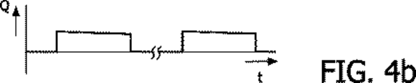
図4は、(a)において、図3に示した電流パルスの半分の継続期間、図3に示した電流パルスと同じ振幅及び図3に示した電流パルスの2倍の周波数を有する電流パルスIのタイムチャートを示している。例として、前記電流パルスは、0.5msの継続期間及び1.5Aの振幅を有し、図3におけるものと同じ発光要素を駆動するための500Hzの繰り返し周波によるものであり得る。従って、図4の電流パルスのデューティサイクルは、図3による電流パルスのデューティサイクルに等しい。図4の場合、前記電流パルスにおける前記発光要素の光生成領域の加熱は、図3の電流パルスにおける前記発光要素の光生成領域の加熱と比較して、低減されており、従って、この結果、図4の(b)に見られるように、光束又は放射束Φの光パルスの振幅のより少ない減少と、当該光パルスのより高い平均振幅及びデューティサイクルをもたらす。 FIG. 4 shows a current pulse I in (a) having a half duration of the current pulse shown in FIG. 3, the same amplitude as the current pulse shown in FIG. 3, and twice the frequency of the current pulse shown in FIG. The time chart is shown. As an example, the current pulse may have a duration of 0.5 ms and an amplitude of 1.5 A, with a repetition frequency of 500 Hz for driving the same light emitting element as in FIG. Therefore, the duty cycle of the current pulse of FIG. 4 is equal to the duty cycle of the current pulse according to FIG. In the case of FIG. 4, the heating of the light generating region of the light emitting element in the current pulse is reduced compared to the heating of the light generating region of the light emitting element in the current pulse of FIG. As can be seen in FIG. 4b, this results in a smaller decrease in the amplitude of the light pulse of the luminous flux or radiant flux Φ and a higher average amplitude and duty cycle of the light pulse.
図5は、(a)において、図3に示されている電流パルスの4分の1の継続期間、図3に示されている電流パルスと同じ振幅、及び図3に示されている電流パルスの4倍の周波数を有する電流パルスIのタイムチャートを示している。例として、前記電流パルスは、0.25msの継続期間及び1.5のAの振幅を有し、図3におけるものと同じ発光要素を駆動するための1kHzの繰り返し周波数によるものであり得る。従って、図5の電流パルスのデューティサイクルは、図3による電流パルスのデューティサイクルに等しい。図5の場合、前記電流パルスにおける前記発光要素の光生成領域の加熱は、図3又は図4の電流パルスにおける前記発光要素の光生成領域の加熱と比較して、低減され、従って、この結果、図5(b)において、分かるように、光束又は放射束Φ光パルスの振幅のより少ない減少と、前記光パルスのより高い平均振幅及びデューティサイクルをもたらす。 FIG. 5 shows in (a) the duration of one quarter of the current pulse shown in FIG. 3, the same amplitude as the current pulse shown in FIG. 3, and the current pulse shown in FIG. 2 shows a time chart of a current pulse I having a frequency four times as high as that of FIG. As an example, the current pulse may have a duration of 0.25 ms and an amplitude of 1.5 A, with a repetition frequency of 1 kHz for driving the same light emitting element as in FIG. Thus, the duty cycle of the current pulse of FIG. 5 is equal to the duty cycle of the current pulse according to FIG. In the case of FIG. 5, the heating of the light generating region of the light emitting element in the current pulse is reduced compared to the heating of the light generating region of the light emitting element in the current pulse of FIG. 3 or FIG. In FIG. 5 (b), as can be seen, there is a smaller decrease in the amplitude of the light flux or radiant flux Φ light pulse, and a higher average amplitude and duty cycle of the light pulse.
図3、4及び5から、電流パルスの持続期間がより小さいほど、電流パルスのシークエンスのデューティサイクルを維持する一方で、前記発光要素によって生成される画像(の一部)の色は、より安定なものになることは、明らかであろう。このことは、前記発光要素の光生成領域が、より一定に保持されることができるからである。更に、前記平均温度は、典型的な発光装置の加熱及び冷却時定数のため、拡張された期間にわたってより低い。 3, 4 and 5, the smaller the duration of the current pulse, the more stable the color of the image produced by the light emitting element while maintaining the duty cycle of the current pulse sequence. It will be clear that it will be. This is because the light generation region of the light emitting element can be kept more constant. Furthermore, the average temperature is lower over an extended period due to the heating and cooling time constants of typical light emitting devices.
図6aは、投影装置における3つの異なる発光要素を駆動するのに使用される画像フレーム期間TFと、照明(フレーム)期間TFのそれぞれの後続している部分B、G及びRの長さによって示されているように、前記発光要素の各々を駆動する相対的な継続期間とを表している。異なる画像に対して、このシーケンス方式BGRは、画像フレーム期間ごとに1回繰り返されることができ、前記発光要素の各々に対する前記駆動パルスの継続期間及び/又は振幅は、所望の色を生成するために変化されることができる。例として、このフレーム周波数は、240Hzであり得る。 FIG. 6a shows the length of the image frame period T F used to drive three different light emitting elements in the projection device and the subsequent parts B, G and R of the illumination (frame) period T F respectively. Represents the relative duration of driving each of the light emitting elements. For different images, this sequencing BGR can be repeated once every image frame period, and the duration and / or amplitude of the drive pulse for each of the light emitting elements to produce the desired color Can be changed. As an example, this frame frequency may be 240 Hz.
図6bは、B、G及びRの発光要素の駆動方式を表しており、前記異なる発光要素の各々の駆動のデューティサイクルは、図6aによる駆動方式のデューティサイクルに等しいが、この周波数は16倍に増大されており、この結果、基本的なシーケンス方式BGRは、画像フレーム期間TFごとに16回繰り返される。例として、このBGR周波数は3.8kHzであり、240Hzのフレーム周波数によるものであり得る。 FIG. 6b shows the driving scheme of the B, G and R light emitting elements, the duty cycle of driving each of the different light emitting elements being equal to the duty cycle of the driving scheme according to FIG. 6a, but this frequency is 16 times. As a result, the basic sequence method BGR is repeated 16 times every image frame period TF . As an example, this BGR frequency is 3.8 kHz and may be due to a frame frequency of 240 Hz.
図6cは、B、G及びR発光要素の他の駆動方式を表しており、前記異なる発光要素の各々の駆動のデューティサイクルは、図6bによる駆動方式のデューティサイクルに等しいが、このRパルスの継続期間は半分にされている一方で、これらの数は、シーケンス方式BRGRにおいて2倍に増大されている。図6bと同様に、基本的なシーケンス方式BRGRは、画像フレーム期間TFごとに16回繰り返される。例えば、前記BRGR周波数は3.8kHzであり、240Hzのフレーム周波数によるものであり得る。 FIG. 6c represents another driving scheme of the B, G and R light emitting elements, the duty cycle of driving each of the different light emitting elements being equal to the duty cycle of the driving scheme according to FIG. While the duration is halved, these numbers are doubled in the sequenced BRGR. Similar to FIG. 6b, the basic sequence method BRGR is repeated 16 times every image frame period TF . For example, the BRGR frequency is 3.8 kHz and may be due to a frame frequency of 240 Hz.
図6dは、B、G及びR発光要素の更に他の駆動方式を表しており、前記異なる発光要素の各々の駆動のデューティサイクルは、図6bによる駆動方式のデューティサイクルに等しいが、このRパルスの時間継続期間は3分の1に減少されている一方で、これらの数は、シーケンス方式RGRGRBにおいて3倍に増大されている。図6bと同様に、この基本的なシーケンス方式RGRGRBは、画像フレーム期間TFごとに16回繰り返される。例として、前記RGRGRB周波数は、3.8kHzであり、240Hzのフレーム周波数によるものであり得る。 FIG. 6d shows yet another driving scheme for the B, G and R light emitting elements, the duty cycle of the driving of each of the different light emitting elements being equal to the duty cycle of the driving scheme according to FIG. While the time duration of is reduced by a factor of three, these numbers are increased by a factor of three in the sequence scheme RGRGRB. Similar to FIG. 6b, this basic sequence scheme RGRGRB is repeated 16 times per image frame period TF . As an example, the RGRGRB frequency is 3.8 kHz and may be due to a frame frequency of 240 Hz.
図6b、6c及び6dによる駆動方式において、増大された平均光出力は、前記画像フレーム期間における発光駆動パルスの同じデューティサイクルにおいて、前記駆動パルスの同じ振幅によって、前記画像フレーム期間にわたって得ることができる。前記発光要素の光生成領域のピークの温度と、1つ以上の画像フレーム期間における平均温度が、減少される。 In the drive scheme according to FIGS. 6b, 6c and 6d, an increased average light output can be obtained over the image frame period with the same amplitude of the drive pulse at the same duty cycle of the light emission drive pulse in the image frame period. . The peak temperature of the light generating region of the light emitting element and the average temperature during one or more image frame periods are reduced.
本発明は、この採用されている高い駆動周波数によって、色の崩壊現象の低減又は除去の更なる利点を提供していることに留意されたい。 It should be noted that the present invention provides the further advantage of reducing or eliminating color collapse phenomena due to the high drive frequency employed.
本発明の特定の実施例が上述されたが、本発明は、上述されているものでない場合にも、実施されることができることはいうまでもない。例えば、本発明の少なくとも一部は、上述された方法(の一部)を記述している機械読み取り可能な命令の1つ以上のシーケンスを含んでいる前記駆動回路内のコンピュータプログラム、又はこれらに記憶されているこのようなコンピュータプログラムを有するデータ記憶媒体(例えば、半導体メモリ、磁気又は光学ディスク)の形態をとることもできる。プログラム、コンピュータプログラム又はソフトウェアアプリケーションは、サブルーチン、関数、手順、オブジェクトメソッド、オブジェクトインプリメンテーション、実行可能なアプリケーション、アプレット、サーブレット、ソースコード、オブジェクトコード、共有されているライブラリ/動的なロードライブラリ、及び/又は、コンピュータシステムにおける実行のために設計されている命令の他のシーケンスを含むものであ得る。 While specific embodiments of the invention have been described above, it will be appreciated that the invention may be practiced otherwise than as described above. For example, at least a portion of the present invention includes a computer program in the drive circuit that includes one or more sequences of machine-readable instructions describing (a part of) the method described above, or It can also take the form of a data storage medium (such as a semiconductor memory, magnetic or optical disk) having such a computer program stored thereon. A program, computer program or software application is a subroutine, function, procedure, object method, object implementation, executable application, applet, servlet, source code, object code, shared library / dynamic load library, And / or may include other sequences of instructions designed for execution in a computer system.
本明細書において使用されている単数形は、1つ以上のものとして規定されている。本明細書において使用されている複数形は、2つ以上のものとして規定されている。本明細書において使用されている、「他の」なる語は、少なくとも第2の又はこれ以上のものとして規定されている。本明細書において使用されている「含む」及び/又は「持つ」なる語は、「有する」(即ち、開放的な言語)として規定されている。 As used herein, the singular forms are defined as one or more. The plural forms used herein are defined as two or more. As used herein, the term “other” is defined as at least a second or more. As used herein, the terms “including” and / or “having” are defined as “having” (ie, an open language).
上述は、説明のためのものであり、限定するためのものではない。従って、当業者であれば、上述された本発明に対する変形が、添付請求項の範囲から逸脱することなく、なされることができることが分かるであろう。 The foregoing is for purposes of illustration and not limitation. Accordingly, those skilled in the art will recognize that modifications to the invention described above can be made without departing from the scope of the appended claims.
Claims (10)
前記発光要素の異なるものを交互に駆動するシーケンス方式を提供するステップと、
前記発光要素を、前記照明期間において少なくとも2回、前記シーケンス方式によって駆動する一方で、各発光要素に関するデューティサイクルは保持しているステップと、
を有する方法であって、
前記シーケンス方式において、全ての前記発光要素のうちで最も高い温度感度を有している発光要素が、他の前記発光要素よりも多い回数において、駆動される、
方法。A method of driving a light source that sequentially emits light generated by at least three light emitting elements each emitting a different primary color, wherein the light emitting element comprises a first light emitting element, a second light emitting element, and a third light emitting element. In the process of image generation, each light emitting element has a duty cycle of the illumination period.
Providing a sequence system for alternately driving different ones of the light emitting elements;
Driving the light emitting elements according to the sequence scheme at least twice during the illumination period while maintaining a duty cycle for each light emitting element;
A method comprising :
In the sequence system, the light emitting element having the highest temperature sensitivity among all the light emitting elements is driven more times than the other light emitting elements.
METHODS.
第1の発光要素と、
第2の発光要素と、
第3の発光要素と、
前記発光要素を各発光要素のための照明期間のデューティサイクルによって、駆動する駆動回路であって、
前記発光要素のうちの異なるものを交互に駆動するシーケンス方式を提供し、
前記発光要素を前記照明期間に少なくとも2回、前記シーケンス方式によって駆動すると共に、各発光要素のための前記デューティサイクルを維持し、
前記シーケンス方式において、全ての前記発光要素のうちで最も高い温度感度を有している発光要素が、他の前記発光要素よりも多い回数において、駆動される、
駆動回路と、
を有する光源装置。A light source device that sequentially emits light of different primary colors,
A first light emitting element;
A second light emitting element;
A third light emitting element;
A driving circuit for driving the light emitting elements by a duty cycle of an illumination period for each light emitting element;
Providing a sequence system for alternately driving different ones of the light emitting elements;
Driving the light emitting elements by the sequence method at least twice during the illumination period, and maintaining the duty cycle for each light emitting element;
In the sequence system, the light emitting element having the highest temperature sensitivity among all the light emitting elements is driven more times than the other light emitting elements .
A drive circuit ;
A light source device having a.
Applications Claiming Priority (3)
| Application Number | Priority Date | Filing Date | Title |
|---|---|---|---|
| EP07109678 | 2007-06-06 | ||
| EP07109678.8 | 2007-06-06 | ||
| PCT/IB2008/052115 WO2008149267A1 (en) | 2007-06-06 | 2008-05-30 | Method and apparatus for driving light emitting elements for projection of images |
Publications (3)
| Publication Number | Publication Date |
|---|---|
| JP2010530983A JP2010530983A (en) | 2010-09-16 |
| JP2010530983A5 JP2010530983A5 (en) | 2011-06-16 |
| JP4850969B2 true JP4850969B2 (en) | 2012-01-11 |
Family
ID=39731263
Family Applications (1)
| Application Number | Title | Priority Date | Filing Date |
|---|---|---|---|
| JP2010510926A Active JP4850969B2 (en) | 2007-06-06 | 2008-05-30 | Method and apparatus for driving a light emitting element for projection of an image |
Country Status (5)
| Country | Link |
|---|---|
| US (1) | US9368071B2 (en) |
| EP (1) | EP2160731B1 (en) |
| JP (1) | JP4850969B2 (en) |
| CN (1) | CN101681598B (en) |
| WO (1) | WO2008149267A1 (en) |
Families Citing this family (28)
| Publication number | Priority date | Publication date | Assignee | Title |
|---|---|---|---|---|
| US20050259424A1 (en) | 2004-05-18 | 2005-11-24 | Zampini Thomas L Ii | Collimating and controlling light produced by light emitting diodes |
| US7766511B2 (en) | 2006-04-24 | 2010-08-03 | Integrated Illumination Systems | LED light fixture |
| US7729941B2 (en) | 2006-11-17 | 2010-06-01 | Integrated Illumination Systems, Inc. | Apparatus and method of using lighting systems to enhance brand recognition |
| US8013538B2 (en) | 2007-01-26 | 2011-09-06 | Integrated Illumination Systems, Inc. | TRI-light |
| US8742686B2 (en) | 2007-09-24 | 2014-06-03 | Integrated Illumination Systems, Inc. | Systems and methods for providing an OEM level networked lighting system |
| US8255487B2 (en) | 2008-05-16 | 2012-08-28 | Integrated Illumination Systems, Inc. | Systems and methods for communicating in a lighting network |
| US8585245B2 (en) | 2009-04-23 | 2013-11-19 | Integrated Illumination Systems, Inc. | Systems and methods for sealing a lighting fixture |
| US8907884B2 (en) * | 2010-01-06 | 2014-12-09 | Apple Inc. | LED backlight system |
| US9066381B2 (en) | 2011-03-16 | 2015-06-23 | Integrated Illumination Systems, Inc. | System and method for low level dimming |
| US9967940B2 (en) | 2011-05-05 | 2018-05-08 | Integrated Illumination Systems, Inc. | Systems and methods for active thermal management |
| US8710770B2 (en) | 2011-07-26 | 2014-04-29 | Hunter Industries, Inc. | Systems and methods for providing power and data to lighting devices |
| US9521725B2 (en) | 2011-07-26 | 2016-12-13 | Hunter Industries, Inc. | Systems and methods for providing power and data to lighting devices |
| US20150237700A1 (en) | 2011-07-26 | 2015-08-20 | Hunter Industries, Inc. | Systems and methods to control color and brightness of lighting devices |
| US10874003B2 (en) | 2011-07-26 | 2020-12-22 | Hunter Industries, Inc. | Systems and methods for providing power and data to devices |
| US11917740B2 (en) | 2011-07-26 | 2024-02-27 | Hunter Industries, Inc. | Systems and methods for providing power and data to devices |
| US9609720B2 (en) | 2011-07-26 | 2017-03-28 | Hunter Industries, Inc. | Systems and methods for providing power and data to lighting devices |
| US8894437B2 (en) | 2012-07-19 | 2014-11-25 | Integrated Illumination Systems, Inc. | Systems and methods for connector enabling vertical removal |
| US9379578B2 (en) | 2012-11-19 | 2016-06-28 | Integrated Illumination Systems, Inc. | Systems and methods for multi-state power management |
| CN103841704B (en) * | 2012-11-23 | 2018-07-27 | 海洋王(东莞)照明科技有限公司 | Led lamp control circuit |
| US9420665B2 (en) | 2012-12-28 | 2016-08-16 | Integration Illumination Systems, Inc. | Systems and methods for continuous adjustment of reference signal to control chip |
| US9485814B2 (en) | 2013-01-04 | 2016-11-01 | Integrated Illumination Systems, Inc. | Systems and methods for a hysteresis based driver using a LED as a voltage reference |
| US10918030B2 (en) | 2015-05-26 | 2021-02-16 | Hunter Industries, Inc. | Decoder systems and methods for irrigation control |
| US10228711B2 (en) | 2015-05-26 | 2019-03-12 | Hunter Industries, Inc. | Decoder systems and methods for irrigation control |
| US10030844B2 (en) | 2015-05-29 | 2018-07-24 | Integrated Illumination Systems, Inc. | Systems, methods and apparatus for illumination using asymmetrical optics |
| US10060599B2 (en) | 2015-05-29 | 2018-08-28 | Integrated Illumination Systems, Inc. | Systems, methods and apparatus for programmable light fixtures |
| US10009570B2 (en) * | 2016-02-24 | 2018-06-26 | International Business Machines Corporation | Thermal management of display screens |
| US10801714B1 (en) | 2019-10-03 | 2020-10-13 | CarJamz, Inc. | Lighting device |
| CN116524852A (en) * | 2023-07-05 | 2023-08-01 | 禹创半导体(深圳)有限公司 | LED display panel and pixel color display method and device thereof |
Citations (6)
| Publication number | Priority date | Publication date | Assignee | Title |
|---|---|---|---|---|
| JPH113051A (en) * | 1997-04-14 | 1999-01-06 | Nichia Chem Ind Ltd | Led display and display device using it |
| JP2001051651A (en) * | 1999-08-05 | 2001-02-23 | Saipaaku:Kk | Light source device and control method |
| JP2004253345A (en) * | 2003-02-18 | 2004-09-09 | Moriwakitto Japan:Kk | Light emitting device |
| JP2006031977A (en) * | 2004-07-12 | 2006-02-02 | Sony Corp | Display device and backlight device |
| JP2006135007A (en) * | 2004-11-04 | 2006-05-25 | Sanyo Electric Co Ltd | Light emitting element |
| US20070120786A1 (en) * | 2005-11-28 | 2007-05-31 | Texas Instruments Incorporated | Sequence design in a display system |
Family Cites Families (13)
| Publication number | Priority date | Publication date | Assignee | Title |
|---|---|---|---|---|
| US20030178950A1 (en) | 2002-03-25 | 2003-09-25 | Chih-Yuan Hsu | Circuit for intermittently illuminating light-emitting device |
| KR100666549B1 (en) * | 2003-11-27 | 2007-01-09 | 삼성에스디아이 주식회사 | AMOLED and Driving method thereof |
| US20060023172A1 (en) | 2004-07-28 | 2006-02-02 | Sanyo Electric Co. | Illuminating device and projection type video display |
| JP4529585B2 (en) | 2004-08-18 | 2010-08-25 | ソニー株式会社 | Display device and control device thereof |
| JP4437110B2 (en) * | 2004-11-17 | 2010-03-24 | 三星モバイルディスプレイ株式會社 | Organic light emitting display device, driving method of organic light emitting display device, and driving method of pixel circuit |
| KR100643764B1 (en) | 2005-03-09 | 2006-11-10 | 삼성전자주식회사 | Image projection apparatus for adjusting white balance by referring to temperature of LED and method thereof |
| US7952112B2 (en) * | 2005-04-29 | 2011-05-31 | Philips Lumileds Lighting Company Llc | RGB thermal isolation substrate |
| NL1031185C2 (en) * | 2006-02-17 | 2007-09-03 | Lemnis Lighting Ip Gmbh | Lighting device and lighting system for promoting plant growth and method for manufacturing and operating a lighting device. |
| US7832878B2 (en) * | 2006-03-06 | 2010-11-16 | Innovations In Optics, Inc. | Light emitting diode projection system |
| TWI333593B (en) * | 2007-03-22 | 2010-11-21 | Young Optics Inc | Illumination module and projection apparatus |
| US8107035B2 (en) * | 2007-04-19 | 2012-01-31 | Necsel Intellectual Property | Laser backlighting for displays |
| KR101266874B1 (en) * | 2008-05-20 | 2013-05-23 | 삼성전자주식회사 | Image projecting apparatus |
| KR101493708B1 (en) * | 2008-12-26 | 2015-02-16 | 삼성전자주식회사 | White light emitting device |
-
2008
- 2008-05-30 JP JP2010510926A patent/JP4850969B2/en active Active
- 2008-05-30 EP EP08763152.9A patent/EP2160731B1/en active Active
- 2008-05-30 CN CN2008800190988A patent/CN101681598B/en active Active
- 2008-05-30 US US12/602,206 patent/US9368071B2/en active Active
- 2008-05-30 WO PCT/IB2008/052115 patent/WO2008149267A1/en active Application Filing
Patent Citations (6)
| Publication number | Priority date | Publication date | Assignee | Title |
|---|---|---|---|---|
| JPH113051A (en) * | 1997-04-14 | 1999-01-06 | Nichia Chem Ind Ltd | Led display and display device using it |
| JP2001051651A (en) * | 1999-08-05 | 2001-02-23 | Saipaaku:Kk | Light source device and control method |
| JP2004253345A (en) * | 2003-02-18 | 2004-09-09 | Moriwakitto Japan:Kk | Light emitting device |
| JP2006031977A (en) * | 2004-07-12 | 2006-02-02 | Sony Corp | Display device and backlight device |
| JP2006135007A (en) * | 2004-11-04 | 2006-05-25 | Sanyo Electric Co Ltd | Light emitting element |
| US20070120786A1 (en) * | 2005-11-28 | 2007-05-31 | Texas Instruments Incorporated | Sequence design in a display system |
Also Published As
| Publication number | Publication date |
|---|---|
| EP2160731A1 (en) | 2010-03-10 |
| JP2010530983A (en) | 2010-09-16 |
| CN101681598B (en) | 2012-11-14 |
| US20100171771A1 (en) | 2010-07-08 |
| CN101681598A (en) | 2010-03-24 |
| WO2008149267A1 (en) | 2008-12-11 |
| EP2160731B1 (en) | 2016-07-13 |
| US9368071B2 (en) | 2016-06-14 |
Similar Documents
| Publication | Publication Date | Title |
|---|---|---|
| JP4850969B2 (en) | Method and apparatus for driving a light emitting element for projection of an image | |
| US7083284B2 (en) | Method and apparatus for sequencing light emitting devices in projection systems | |
| JP5296101B2 (en) | Multicolor light source | |
| JP2008525826A (en) | Field sequential display of color images | |
| US9363872B2 (en) | Display device and method of controlling light source | |
| JP2007171480A (en) | Image display device | |
| JP2006301649A (en) | Method and system for projecting image | |
| KR20080073464A (en) | Apparatus for driving of light source and display device having the same and method of the driving | |
| JP2010231142A (en) | Display apparatus and method of driving the same | |
| JP2009232308A (en) | Image displaying apparatus, and image displaying method | |
| JPWO2019064985A1 (en) | Display device | |
| JP2012048209A (en) | Projection type video display device | |
| JP2008164749A (en) | Image display device and method | |
| TW200845744A (en) | Method of adjusting the light output of a projector system, and system for adjusting the light output of a projector system | |
| JP2006030401A (en) | Display device and display method, recoding medium and program | |
| JP5446721B2 (en) | Discharge lamp lighting device and projection-type image display device | |
| JP2009175627A (en) | Image display device and electronic apparatus | |
| JP2005181528A (en) | Light emitting diode type projecting device | |
| JP2005309134A (en) | Video display device and its light source unit | |
| JP2018194567A (en) | Light-emitting device, display device and method for controlling light-emitting device | |
| JP6256997B2 (en) | Backlight device, display device, and backlight control method | |
| JP2012043611A (en) | Illumination device and display device | |
| JP2015203741A (en) | Projection type video display device | |
| KR20120012877A (en) | Apparatus for Controlling LED Light Source | |
| JP5525341B2 (en) | Dual modulation display device and driving program thereof |
Legal Events
| Date | Code | Title | Description |
|---|---|---|---|
| A521 | Request for written amendment filed |
Free format text: JAPANESE INTERMEDIATE CODE: A523 Effective date: 20110426 |
|
| A621 | Written request for application examination |
Free format text: JAPANESE INTERMEDIATE CODE: A621 Effective date: 20110426 |
|
| A871 | Explanation of circumstances concerning accelerated examination |
Free format text: JAPANESE INTERMEDIATE CODE: A871 Effective date: 20110426 |
|
| A975 | Report on accelerated examination |
Free format text: JAPANESE INTERMEDIATE CODE: A971005 Effective date: 20110517 |
|
| A131 | Notification of reasons for refusal |
Free format text: JAPANESE INTERMEDIATE CODE: A131 Effective date: 20110531 |
|
| A521 | Request for written amendment filed |
Free format text: JAPANESE INTERMEDIATE CODE: A523 Effective date: 20110826 |
|
| TRDD | Decision of grant or rejection written | ||
| A01 | Written decision to grant a patent or to grant a registration (utility model) |
Free format text: JAPANESE INTERMEDIATE CODE: A01 Effective date: 20110920 |
|
| A01 | Written decision to grant a patent or to grant a registration (utility model) |
Free format text: JAPANESE INTERMEDIATE CODE: A01 |
|
| A61 | First payment of annual fees (during grant procedure) |
Free format text: JAPANESE INTERMEDIATE CODE: A61 Effective date: 20111019 |
|
| R150 | Certificate of patent or registration of utility model |
Ref document number: 4850969 Country of ref document: JP Free format text: JAPANESE INTERMEDIATE CODE: R150 Free format text: JAPANESE INTERMEDIATE CODE: R150 |
|
| FPAY | Renewal fee payment (event date is renewal date of database) |
Free format text: PAYMENT UNTIL: 20141028 Year of fee payment: 3 |
|
| R250 | Receipt of annual fees |
Free format text: JAPANESE INTERMEDIATE CODE: R250 |
|
| R250 | Receipt of annual fees |
Free format text: JAPANESE INTERMEDIATE CODE: R250 |
|
| S531 | Written request for registration of change of domicile |
Free format text: JAPANESE INTERMEDIATE CODE: R313531 |
|
| S533 | Written request for registration of change of name |
Free format text: JAPANESE INTERMEDIATE CODE: R313533 |
|
| R350 | Written notification of registration of transfer |
Free format text: JAPANESE INTERMEDIATE CODE: R350 |
|
| S111 | Request for change of ownership or part of ownership |
Free format text: JAPANESE INTERMEDIATE CODE: R313113 |
|
| R350 | Written notification of registration of transfer |
Free format text: JAPANESE INTERMEDIATE CODE: R350 |
|
| R250 | Receipt of annual fees |
Free format text: JAPANESE INTERMEDIATE CODE: R250 |
|
| R250 | Receipt of annual fees |
Free format text: JAPANESE INTERMEDIATE CODE: R250 |
|
| R250 | Receipt of annual fees |
Free format text: JAPANESE INTERMEDIATE CODE: R250 |
|
| S531 | Written request for registration of change of domicile |
Free format text: JAPANESE INTERMEDIATE CODE: R313531 |
|
| S533 | Written request for registration of change of name |
Free format text: JAPANESE INTERMEDIATE CODE: R313533 |
|
| R250 | Receipt of annual fees |
Free format text: JAPANESE INTERMEDIATE CODE: R250 |
|
| R350 | Written notification of registration of transfer |
Free format text: JAPANESE INTERMEDIATE CODE: R350 |
|
| R250 | Receipt of annual fees |
Free format text: JAPANESE INTERMEDIATE CODE: R250 |
|
| R250 | Receipt of annual fees |
Free format text: JAPANESE INTERMEDIATE CODE: R250 |
|
| R250 | Receipt of annual fees |
Free format text: JAPANESE INTERMEDIATE CODE: R250 |