JP4850737B2 - Wireless communication device - Google Patents
Wireless communication device Download PDFInfo
- Publication number
- JP4850737B2 JP4850737B2 JP2007024452A JP2007024452A JP4850737B2 JP 4850737 B2 JP4850737 B2 JP 4850737B2 JP 2007024452 A JP2007024452 A JP 2007024452A JP 2007024452 A JP2007024452 A JP 2007024452A JP 4850737 B2 JP4850737 B2 JP 4850737B2
- Authority
- JP
- Japan
- Prior art keywords
- transmission
- line quality
- value
- wireless communication
- channel
- Prior art date
- Legal status (The legal status is an assumption and is not a legal conclusion. Google has not performed a legal analysis and makes no representation as to the accuracy of the status listed.)
- Expired - Fee Related
Links
Images
Landscapes
- Time-Division Multiplex Systems (AREA)
- Mobile Radio Communication Systems (AREA)
Description
本発明は、ランダムアクセスチャネルを用いる無線通信装置に関するものである。 The present invention relates to a wireless communication apparatus using a random access channel.
従来、ランダムアクセスを行うセルラー端末を含む無線通信システムにおいては、各端末は基地局から通知されるランダムアクセスチャネルにおいて、基地局から許可されたスロットでランダムアクセスを行う(たとえば、下記非特許文献1参照)。具体的には、基地局は、制御情報の一部として次スロットが送信許可スロットであるか否かを報知している(下記非特許文献1 4.1.13.1章 p135参照)。各端末は、送信データが発生すると、基地局から報知された制御情報を確認し、送信許可スロットにおいてSCCH(Signaling Control CHannel)を用いてデータの送信を行う。 Conventionally, in a wireless communication system including a cellular terminal that performs random access, each terminal performs random access in a slot permitted from the base station in a random access channel notified from the base station (for example, Non-Patent Document 1 below). reference). Specifically, the base station broadcasts whether or not the next slot is a transmission-permitted slot as a part of the control information (see Non-Patent Document 1 chapter 4.1.13.1 p135 below). When transmission data is generated, each terminal confirms control information broadcast from the base station, and transmits data using SCCH (Signaling Control CHannel) in a transmission permission slot.
しかしながら、上記従来の技術によれば、送信データが発生した時点で送信が許可されているスロットでランダムアクセスチャネルの送信を行うため、即時性の点では有効であるが、端末の受信レベルを考慮していないため、端末の受信レベルが低い場合には受信確率が低下しているにもかかわらず送信を行うことになる。したがって、このような場合には、結果的に無駄な送信を行い、端末電力を浪費するという問題があった。また、このような無駄な送信により、他端末から送信される送信データと競合を起こし、他端末に無駄な干渉を与える問題があった。 However, according to the above-described conventional technique, since the random access channel is transmitted in the slot that is permitted to transmit when transmission data is generated, it is effective in terms of immediacy, but the reception level of the terminal is considered. Therefore, when the reception level of the terminal is low, transmission is performed even though the reception probability is low. Therefore, in such a case, there has been a problem that as a result, useless transmission is performed and terminal power is wasted. In addition, such useless transmission causes a problem with transmission data transmitted from other terminals and causes other terminals to have useless interference.
本発明は、上記に鑑みてなされたものであって、高い受信効率でランダムアクセスチャネルの送信を行うことができる無線通信装置を得ることを目的とする。 The present invention has been made in view of the above, and an object of the present invention is to obtain a wireless communication apparatus capable of transmitting a random access channel with high reception efficiency.
上述した課題を解決し、目的を達成するために、本発明は、ランダムアクセスチャネルを用いてデータ送信を行う無線通信装置であって、受信信号に基づき回線品質を測定する回線品質測定手段と、前記回線品質に基づきランダムアクセスチャネルの送信タイミングを決定する制御手段と、を備えることを特徴とする。 In order to solve the above-described problems and achieve the object, the present invention is a wireless communication apparatus that performs data transmission using a random access channel, and a line quality measurement unit that measures line quality based on a received signal; Control means for determining transmission timing of a random access channel based on the channel quality.
この発明によれば、回線品質を測定し、測定した回線品質に基づきランダムアクセスチャネルの送信のタイミングを調整するようにしたので、高い受信効率でランダムアクセスチャネルの送信を行うことができるという効果を奏する。 According to the present invention, the channel quality is measured, and the transmission timing of the random access channel is adjusted based on the measured channel quality, so that the random access channel can be transmitted with high reception efficiency. Play.
以下に、本発明にかかる無線通信装置の実施の形態を図面に基づいて詳細に説明する。なお、この実施の形態によりこの発明が限定されるものではない。 Embodiments of a wireless communication apparatus according to the present invention will be described below in detail with reference to the drawings. Note that the present invention is not limited to the embodiments.
実施の形態1.
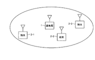
図1は、本発明にかかる無線通信システムの実施の形態1の構成例を示す図である。図1に示すように、本実施の形態の無線通信システムは、複数の端末との無線信号を制御する基地局1と、無線通信を行う端末2−1〜2−3で構成される。本実施の形態では、本発明にかかる無線通信装置の一例を端末2−1〜2−3として説明する。なお、図1では端末の数を3としているが、これに限らず、端末の数はいくつでもよい。
Embodiment 1 FIG.
FIG. 1 is a diagram showing a configuration example of a first embodiment of a wireless communication system according to the present invention. As shown in FIG. 1, the wireless communication system according to the present embodiment includes a base station 1 that controls wireless signals with a plurality of terminals and terminals 2-1 to 2-3 that perform wireless communication. In the present embodiment, an example of a wireless communication device according to the present invention will be described as terminals 2-1 to 2-3. In FIG. 1, the number of terminals is three, but the number is not limited to this, and any number of terminals may be used.
本実施の形態の無線通信システムの無線信号の制御動作として、たとえば、端末2−1〜2−3は、通信を行うために基地局1に対して位置登録,認証等を行う。そして、端末2−1〜2−3は、基地局1の制御に基づいて基地局1に対してユーザ情報の送信を行い、また、基地局1から送信される各端末向けの情報取得を行う。無線信号の制御動作としては、これに限らず、基地局1が端末2−1〜2−3を制御するものであればどのようなものでもよい。 As a radio signal control operation of the radio communication system according to the present embodiment, for example, the terminals 2-1 to 2-3 perform location registration, authentication, and the like for the base station 1 in order to perform communication. Then, the terminals 2-1 to 2-3 transmit user information to the base station 1 based on the control of the base station 1, and acquire information for each terminal transmitted from the base station 1. . The radio signal control operation is not limited to this, and any operation may be used as long as the base station 1 controls the terminals 2-1 to 2-3.
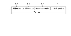
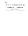
つぎに、本実施の形態の無線通信システムのフレーム構成について説明する。図2は、TDMA−TDD(Time Division Multiple Access−Time Division Duplex)のフレームのチャネル構成例を示す図である。図2に示すように、TDMA−TDDのフレームは、基地局1から複数の端末へ制御情報などの共通の下り信号を送信する共通チャネル3−1と、複数のスロットで構成され、基地局1から特定の端末へ送信する下り個別チャネル3−2と、複数のスロットで構成され、端末2−1〜2−3が基地局1へランダムにアクセスするランダムアクセスチャネル3−3と、複数のスロットから構成され、端末2−1〜2−3が基地局へ送信する上り個別チャネル3−4と、で構成される。 Next, a frame configuration of the radio communication system according to the present embodiment will be described. FIG. 2 is a diagram illustrating a channel configuration example of a TDMA-TDD (Time Division Multiple Access-Time Division Duplex) frame. As shown in FIG. 2, a TDMA-TDD frame is composed of a common channel 3-1 for transmitting a common downlink signal such as control information from the base station 1 to a plurality of terminals, and a plurality of slots. Downlink dedicated channel 3-2 for transmitting to a specific terminal and a plurality of slots, a random access channel 3-3 for randomly accessing the base station 1 by the terminals 2-1 to 2-3, and a plurality of slots And an uplink dedicated channel 3-4 transmitted from the terminals 2-1 to 2-3 to the base station.
なお、本実施の形態では、TDMA−TDDを例として説明してするが、伝送方式は、これに限らず、CDMA(Code Division Multiple Access),OFDM(Orthogonal Frequency Division Multiplexing)など他の伝送方式を用いてもよい。また、フレーム内のチャネル構成やチャネル配置についても、これにかぎらず、ランダムアクセスチャネルを含むものであればよく、チャネル構成およびチャネル配置に限定はない。たとえば、共通チャネルと個別チャネルの間にランダムアクセスチャネルが配置されていても良い。 In this embodiment, TDMA-TDD is described as an example. However, the transmission method is not limited to this, and other transmission methods such as CDMA (Code Division Multiple Access) and OFDM (Orthogonal Frequency Division Multiplexing) are used. It may be used. In addition, the channel configuration and channel arrangement in the frame are not limited to this, and any channel including a random access channel may be used, and the channel configuration and channel arrangement are not limited. For example, a random access channel may be arranged between the common channel and the dedicated channel.
つづいて、本実施の形態の端末2−1〜2−3について説明する。図3は、本実施の形態の端末2−1の機能構成例を示す図である。端末2−2および端末2−3も端末2−1と同様の構成とする。図3に示すように、本実施の形態の端末2−1は、無線信号を送受信するアンテナ4と、送信と受信を切り替えるスイッチ(SW)5と、受信信号を復調する復調部6と、復調部6で得られるAGC(Auto Gain Control)ゲイン値や振幅情報に基づき回線品質情報を測定する回線品質情報測定部7と、測定した回線品質情報に基づき平均値や分散値を求め、送受信データの制御を行う制御部8と、送信データを変調する変調部9と、で構成される。
Next, terminals 2-1 to 2-3 according to the present embodiment will be described. FIG. 3 is a diagram illustrating a functional configuration example of the terminal 2-1 according to the present embodiment. The terminal 2-2 and the terminal 2-3 have the same configuration as the terminal 2-1. As shown in FIG. 3, the terminal 2-1 of this embodiment includes an antenna 4 that transmits and receives radio signals, a switch (SW) 5 that switches between transmission and reception, a demodulator 6 that demodulates received signals, and a demodulator. A channel quality
端末2−1では、まず、アンテナ4が無線信号を受信し、SW5が受信に切り替えを行い、復調部6が、受信した無線信号を復調し、復調された受信データを得る。復調部6が、復調を行う際に得られるAGCゲイン値や振幅情報を回線品質情報測定部7に送出し、回線品質情報測定部7がRSSI(Received Signal Strength Indicator)などの回線品質情報を測定する。制御部8は、受信データの共通チャネル3−1を解析してフレーム内のチャネル構成を解読し、測定した回線品質情報に基づき、共通チャネル3−1と下り個別チャネル3−2の回線品質情報の瞬時値,平均値,分散値を求める。ここで、回線品質情報の瞬時値,平均値,分散値を以下の式(1)のように定義する。
瞬時値=所定の期間の回線品質情報の平均値
平均値=測定区間(1フレーム分以上)の回線品質情報の平均値
分散値=Σ((回線品質情報 − 平均値)2) …(1)
In the terminal 2-1, first, the antenna 4 receives a radio signal, the SW 5 switches to reception, and the demodulation unit 6 demodulates the received radio signal to obtain demodulated reception data. The demodulator 6 sends the AGC gain value and amplitude information obtained at the time of demodulation to the channel quality
Instantaneous value = Average value of channel quality information for a predetermined period = Average value of channel quality information in measurement interval (1 frame or more) = Σ ((line quality information-average value) 2 ) (1)
本実施の形態では、瞬時値を、測定区間内の回線品質の変動を含む値として求めるが、たとえば、周波数オフセットダイバーシチ効果の結果に生じる高速フェージングの影響などについては除いて求める必要がある。このような高速フェージングは常に発生しており、端末の回線品質の変動を表すものではないためである。また、真に瞬間的な変化まで考慮すると、回線品質測定時と、その情報を用いて送信を行う時とで、回線品質情報に大きく差がでる可能性もある。このような高速フェージングなどの影響を除去する方法としては、本実施の形態では、瞬時値を所定の期間の回線品質情報の平均値として求める。所定の期間としては、たとえば、高速フェージングの周期以上の期間を設定すればよい。 In the present embodiment, the instantaneous value is obtained as a value including fluctuations in the channel quality within the measurement interval, but it is necessary to obtain the instantaneous value excluding, for example, the influence of fast fading that occurs as a result of the frequency offset diversity effect. This is because such fast fading always occurs and does not represent a change in terminal line quality. Considering even a truly instantaneous change, there is a possibility that there is a great difference in the line quality information between the time when the line quality is measured and the time when transmission is performed using the information. As a method for removing the influence of such high-speed fading, in this embodiment, an instantaneous value is obtained as an average value of channel quality information for a predetermined period. As the predetermined period, for example, a period equal to or higher than the fast fading period may be set.
また、分散値を求めるにあたり、測定値のサンプリング間隔を端末の種別(静止専用端末,移動端末など)ごとに異なるようにしても良い。たとえば、UHF(Ultra High Frequency)帯において30[km/h]の移動を想定するとフェージング周波数が5Hz程度となり、フェージング周期は200[mS]程度となる。この場合、フェージング変動の分散値を正しく算出するためには、サンプリング間隔は、長くても50[mS](1/4周期)程度以下とする必要がある。 Further, when obtaining the variance value, the sampling interval of the measurement values may be different for each type of terminal (stationary dedicated terminal, mobile terminal, etc.). For example, assuming a movement of 30 [km / h] in a UHF (Ultra High Frequency) band, the fading frequency is about 5 Hz, and the fading cycle is about 200 [mS]. In this case, in order to correctly calculate the dispersion value of the fading fluctuation, the sampling interval needs to be about 50 [mS] (1/4 cycle) or less at the longest.
なお、本実施の形態では、共通チャネル3−1と下り個別チャネル3−2の回線品質情報の瞬時値,平均値,分散値を求めるようにしたが、共通チャネル3−1のみ、下り個別チャネル3−2のみの回線品質情報の瞬時値,平均値,分散値を求めるようにしてもよい。 In this embodiment, the instantaneous value, average value, and dispersion value of the channel quality information of the common channel 3-1 and the downlink dedicated channel 3-2 are obtained. You may make it obtain | require the instantaneous value of the channel quality information of only 3-2, an average value, and a dispersion value.
つづいて、本実施の形態における端末2−1のランダムアクセスチャネルのデータ送信動作について説明する。端末2−2,2−3のデータ送信動作についても端末2−1と同様である。本実施の形態のランダムアクセスチャネルのデータ送信では、回線品質が良好な場合には、従来と同様に一様ランダムにデータを送信し、回線品質が良好でなく、かつ、測定区間の分散値などが大きい場合(変動が大きい場合)には、回線品質が良好な場合より優先して(先に)データを送信する。回線品質状態の良い端末の場合は、一様ランダムにアクセスを行っても受信確率は高く、また、このような場合に送信スロットを限定すると複数の端末で送信が集中し衝突が生じる可能性があるため、送信タイミングを分散させるために、従来と同様に一様ランダムに送信を行う。一方、回線品質が良好でなく、かつ、測定区間の分散などが大きい場合(変動が大きい場合)は、常に回線品質が悪い場合とは異なり、データ送信を行うと基地局1が受信できる可能性がある。したがって、このような場合には、回線品質が良好な場合より優先して送信することにより、さらに品質が劣化する前にデータを送信することができる。 Next, the data transmission operation of the random access channel of terminal 2-1 in the present embodiment will be described. The data transmission operation of the terminals 2-2 and 2-3 is the same as that of the terminal 2-1. In the random access channel data transmission according to the present embodiment, when the line quality is good, the data is uniformly and randomly transmitted as in the conventional case, the line quality is not good, and the dispersion value of the measurement interval, etc. Is large (when the fluctuation is large), data is transmitted prior to the case where the channel quality is good (first). In the case of a terminal with a good channel quality state, the probability of reception is high even if it is accessed uniformly at random, and in such a case, if the transmission slots are limited, there is a possibility that transmission will concentrate on multiple terminals and a collision will occur. Therefore, in order to disperse the transmission timing, transmission is performed uniformly and randomly as in the conventional case. On the other hand, when the line quality is not good and the variance of the measurement interval is large (when the fluctuation is large), unlike the case where the line quality is always poor, there is a possibility that the base station 1 can receive data transmission. There is. Therefore, in such a case, the data can be transmitted before the quality further deteriorates by giving priority to the transmission over the case where the line quality is good.
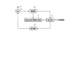
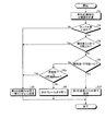
図4は、本実施の形態の端末2−1のデータ送信のフローチャートである。まず、送信データが発生すると送信動作の開始となる。そして、上述のとおりアンテナ4が無線信号を受信し、SW5および復調部6経由で、回線品質情報測定部が回線品質情報を測定し、制御部8が、回線品質情報に基づき上記式(1)にしたがって瞬時値,平均値,分散値を求める(ステップS1)。なお、ここでは、送信データが発生した場合に、回線品質情報を測定するようにしたが、送信データの発生がなくても、無線信号の受信のたびに回線品質情報を測定するようにしてもよい。 FIG. 4 is a flowchart of data transmission of terminal 2-1 according to the present embodiment. First, when transmission data is generated, a transmission operation is started. Then, as described above, the antenna 4 receives the radio signal, the channel quality information measuring unit measures the channel quality information via the SW 5 and the demodulating unit 6, and the control unit 8 uses the above formula (1) based on the channel quality information. The instantaneous value, average value, and dispersion value are obtained according to (Step S1). Here, the channel quality information is measured when transmission data is generated, but the channel quality information may be measured every time a radio signal is received even if transmission data is not generated. Good.
つぎに、制御部8は、瞬時値が閾値A以上かつ分散値が閾値B未満であるかを判断する(ステップS2)。閾値A及びBは、回線品質が良好であるかの判定のための閾値であり、たとえば、基地局1が通知するか、または、端末2−1にあらかじめ設定しておく。瞬時値が閾値A以上かつ分散値が閾値B未満である場合(ステップS2 Yes)には、通常送信として、従来のランダムアクセスチャネルの送信と同様にランダムアクセスチャネルのスロット内で一様ランダムに送信を行う(ステップS3)。具体的には、制御部8が、一様ランダムアクセスチャネルにおいて一様ランダムなタイミングで変調部9に送信データの変調を指示し、変調部9は送信データを変調してSW5に送出し、SW5は送信に切り替えを行い変調した送信データを送信信号としてアンテナ4に送出して、アンテナ4が送信信号を送信する。なお、変調部9における変調処理はステップS3までに行っておき、制御部8は、ランダムアクセスチャネルにおいて一様ランダムなタイミングで、変調部9に対して変調した送信データの送出を指示するようにしてもよい。
Next, the control unit 8 determines whether the instantaneous value is greater than or equal to the threshold value A and the variance value is less than the threshold value B (step S2). The thresholds A and B are thresholds for determining whether the line quality is good. For example, the base station 1 notifies the thresholds A and B, or is set in advance in the terminal 2-1. When the instantaneous value is greater than or equal to the threshold value A and the variance value is less than the threshold value B (Yes in step S2), transmission is performed uniformly and randomly within the slot of the random access channel as normal transmission, as normal transmission. Is performed (step S3). Specifically, the control unit 8 instructs the
なお、ここでは、ステップS2において、瞬時値と分散値の両方について閾値と比較による判断を行ったが、瞬時値のみまたは分散値のみを閾値と比較して判断するようにしても良い。また、ここでは、ステップS2において、瞬時値と分散値の両方について閾値と比較による判断を行ったが、ステップS2の判断は行わなくても良い。さらに、この発明において、単に「回線品質」とは、「回線品質平均値」「回線品質瞬時値」「回線品質分散値」の少なくともいずれか1つを意味するものとする。 Here, in step S2, both the instantaneous value and the variance value are determined by comparison with the threshold value. However, the determination may be made by comparing only the instantaneous value or only the variance value with the threshold value. Further, here, in step S2, the determination is made by comparing the threshold value and the instantaneous value and the variance value, but the determination in step S2 may not be performed. Further, in the present invention, simply “line quality” means at least one of “line quality average value”, “line quality instantaneous value”, and “line quality variance value”.
瞬時値が閾値A以上かつ分散値が閾値B未満でない場合(ステップS2 No)には、制御部8は、“「瞬時値−平均値」が閾値C以上”であるかを判断する(ステップS4)。Cは、通信品質が良好であるか否かを判定するためにあらかじめ定められた閾値であり、基地局1から共通チャネルによって通知される。または、端末2−1がそれぞれ閾値Cを設定しておくようにしてもよい。 When the instantaneous value is not less than the threshold value A and the variance value is not less than the threshold value B (No in step S2), the control unit 8 determines whether ““ instantaneous value−average value ”is not less than the threshold value C” (step S4). C is a predetermined threshold for determining whether or not the communication quality is good, and is notified by the common channel from the base station 1. Alternatively, the terminal 2-1 sets the threshold C respectively. You may make it keep.
制御部8が、“「瞬時値−平均値」が閾値C以上”であると判断した場合(ステップS4 Yes)には、ステップS7にすすみ、“「瞬時値−平均値」が閾値C以上”でないと判断した場合(「瞬時値−平均値」が閾値C未満の場合:ステップS4 No)は、ステップS5にすすむ。 When the control unit 8 determines that “the“ instantaneous value−average value ”is equal to or greater than the threshold value C” (Yes in step S4), the control unit 8 proceeds to step S7, and “the“ instantaneous value−average value ”is equal to or greater than the threshold value C”. If it is determined that it is not (“instantaneous value−average value” is less than the threshold C: No in step S4), the process proceeds to step S5.
ステップS5では、制御部8が、緊急呼であるか、または、N回連続で待機状態(wait状態)であるかどうかを判断する。緊急呼またはN回連続で待機状態(wait状態)でない場合(緊急呼でなく、かつ、N回連続待機状態でない場合:ステップS5 No)には、送信を保留し次のフレームまで待機とし、連続待機の場合には連続待機回数に1を加え、連続待機でない場合には連続待機回数を1として保持し(ステップS6)、そのフレームの処理を終了する。ステップS5において、制御部8が、緊急呼であるか、または、N回連続で待機状態(wait状態)であると判断した場合(ステップS5 Yes)は、ステップS7にすすむ。 In step S5, the control unit 8 determines whether the call is an emergency call or is in a standby state (wait state) for N consecutive times. If it is not an emergency call or N consecutive consecutive standby states (wait state) (not an emergency call and not N consecutive continuous standby state: No in step S5), the transmission is suspended and the next frame is waited for. In the case of standby, 1 is added to the number of continuous standbys, and when it is not continuous standby, the number of continuous standbys is held as 1 (step S6), and the processing of the frame is terminated. In step S5, when the control unit 8 determines that the call is an emergency call or is in a standby state (wait state) N times continuously (Yes in step S5), the process proceeds to step S7.
ステップS4で、“「瞬時値−平均値」が閾値C以上”でないと判断される場合は、その測定区間において回線品質が常に悪いことを示す。このような場合に、基地局1にデータを送信しても、受信される確率が低いため、送信電力の浪費を防ぐためにステップ6において送信を保留する。しかし、無条件に保留を続けると、たとえば、常に不感地帯に存在するような端末は、連続して待機状態となってしまい、送信ができなくなってしまう。このような状態を避けるために、ステップ5においてN回連続待機状態であるかの判断を加え、N回連続待機状態である場合には保留は行わない。 If it is determined in step S4 that “the“ instantaneous value−average value ”is not equal to or greater than the threshold value C”, it indicates that the channel quality is always poor in the measurement section. Even if it is transmitted, since the probability of being received is low, the transmission is suspended in step 6 to prevent waste of transmission power, but if the suspension is continued unconditionally, for example, a terminal that always exists in the dead zone. In order to avoid such a state, it is determined in step 5 whether or not it is in the Nth continuous standby state, and it is in the Nth continuous standby state. In some cases, no hold is made.
緊急呼とは、データ種別が緊急を要する種別が指定されている送信データの送信のことである。このように緊急性が高いデータについては保留を行わないことで送信データの遅延を抑制する。なお、このような緊急のデータ種別の無い無線通信システムの場合には、ステップS6において、緊急呼であるかどうかの判断は行う必要はなく、N回連続で待機状態であるかのみを判断すればよい。 An emergency call is transmission of transmission data in which a data type is designated as an emergency type. As described above, delay of transmission data is suppressed by not holding data with high urgency. In the case of a wireless communication system without such an urgent data type, it is not necessary to determine whether or not the call is an emergency call in step S6, but only whether it is in a standby state N times continuously. That's fine.
ステップS7では、送信信号を優先して(なるべく早く)送信する(ステップS7)。たとえば、ランダムアクセスチャネル内の送信に使用できるスロットのうち、スロット番号の若い順(送信の早い順)にスロットを割当てて送信する。具体的には、制御部8がスロットを割当て、割当てたスロットにおいて、変調部9に送信データの変調を指示し、変調部9は送信データを変調してSW5に送出し、SW5は送信に切り替えを行い変調した送信データを送信信号としてアンテナ4に送出して、アンテナ4が送信信号を送信する。なお、変調部9における変調処理はステップS7までに行っておき、制御部8は、割当てたスロットにおいて、変調部9に対して変調した送信データの送出を指示するようにしてもよい。
In step S7, the transmission signal is transmitted with priority (as soon as possible) (step S7). For example, among slots that can be used for transmission in the random access channel, slots are assigned in ascending order of slot numbers (in the order of transmission) and transmitted. Specifically, the control unit 8 assigns a slot, and in the assigned slot, instructs the
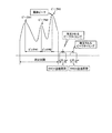
さらに、ステップS7において、以下のように回線品質情報がピーク値となるタイミング(以下、ピークタイミングという)を推定して、ピークタイミングを用いてランダムアクセスチャネルの送信スロット(RACH(Random Access Channel)送信区間)を割当てる処理を行うと、基地局における受信確率を向上させることができる。まず、制御部8は、回線品質情報のピーク値を求める。ピーク値の求め方としては、たとえば、ピーク値を初期値に設定して(たとえば0に設定する)、2測定ポイント間の傾きを順次算出し、この傾きが正になる間は、回線品質情報の値が増加しているため、ピーク値を順次回線品質情報の値に更新する。そして、傾きがk回連続(kは正の整数)負になると、それまでのピーク値をピーク値#1として格納して、ピーク値を初期値に設定し、同様にしてピーク値#2を求めて格納し、ピーク値を初期値に設定する。これを繰り返すことにより、ピーク値#1,#2,・・・と求めていくことができる。これに限らずピーク値を順次求める方法であればどのような方法でもよい。 Further, in step S7, the timing at which the channel quality information reaches a peak value (hereinafter referred to as peak timing) is estimated as described below, and a random access channel transmission slot (RACH (Random Access Channel) transmission is performed using the peak timing. When the process of assigning (interval) is performed, the reception probability at the base station can be improved. First, the control unit 8 obtains a peak value of the line quality information. As a method for obtaining the peak value, for example, the peak value is set to an initial value (for example, set to 0), and the slope between two measurement points is sequentially calculated. Since the value of is increased, the peak value is sequentially updated to the value of the line quality information. When the slope becomes k times consecutively (k is a positive integer) and negative, the previous peak value is stored as the peak value # 1, the peak value is set to the initial value, and the peak value # 2 is similarly set. Obtain and store, and set the peak value to the initial value. By repeating this, peak values # 1, # 2,... Can be obtained. The method is not limited to this, and any method may be used as long as the peak values are obtained sequentially.
つぎに、このようにして求めたピーク値#1,#2,・・・を用いて回線品質情報の変動の周期の平均値を求めてピークタイミングを推定する。ここでは回線品質情報の変動がフェージングによるものとして説明する。フェージング周期の平均値は、測定区間のピーク値の間隔の平均をとることにより求めることができる。たとえば、図5に示すように、測定区間にフェージングによる3つのピーク(ピーク値#1,#2,#3とする)があるとする。図5の場合には、ピッチ1をピーク値#1とピーク値#2の間隔として算出し、ピッチ2をピーク値#2とピーク値#3の間隔として算出し、ピーク1とピーク2の平均をとることによりフェージング周期の平均値を求め、フェージング周期の推定値とする。なお、本実施の形態では、フェージングの周期の推定値を測定区間の平均値として求めたが、平均値のかわりに最新のフェージング周期(図5の例ではピッチ2)のみを用いてもよい。 Next, using the peak values # 1, # 2,... Obtained in this way, the average value of the period of fluctuation of the channel quality information is obtained to estimate the peak timing. Here, description will be made assuming that the fluctuation of the channel quality information is due to fading. The average value of the fading period can be obtained by taking the average of the peak values in the measurement interval. For example, as shown in FIG. 5, it is assumed that there are three peaks due to fading (peak values # 1, # 2, and # 3) in the measurement interval. In the case of FIG. 5, pitch 1 is calculated as the interval between peak value # 1 and peak value # 2, pitch 2 is calculated as the interval between peak value # 2 and peak value # 3, and the average of peak 1 and peak 2 is calculated. By taking the above, the average value of the fading period is obtained and used as the estimated value of the fading period. In the present embodiment, the estimated value of the fading period is obtained as the average value of the measurement interval, but only the latest fading period (pitch 2 in the example of FIG. 5) may be used instead of the average value.
つぎに、測定区間の最新のピーク値の時刻にフェージング周期の推定値を加えてピークタイミングの推定値とする。そして、割当てる送信スロットをピークタイミングから±Mスロットとする。さらに、フェージング周期の推定値の2倍,3倍,…を最新のピーク値の時刻に加えてピークタイミングの推定値を複数求め、それぞれピークタイミングの推定値±Mスロットを送信スロットとして割当てるようにしてもよい。Mの値は、特に制約はないが、たとえば、基地局1が通信状態などに応じて算出し、共通チャネル3−1により通知する。または、制御部8が、たとえば、Mの値をフェージングピッチの1/Xに相当するスロット数として求めてもよい。このとき、Xの値はあらかじめ端末2−1に設定するようにしてもよいし、基地局1から共通チャネル3−1により指定されるようにしても良い。 Next, an estimated value of the fading period is added to the time of the latest peak value in the measurement interval to obtain an estimated value of peak timing. The transmission slot to be assigned is set to ± M slots from the peak timing. Further, twice, three times, ... of the estimated value of the fading period are added to the time of the latest peak value to obtain a plurality of estimated values of peak timing, and each of the estimated values of peak timing ± M slots is assigned as a transmission slot. May be. The value of M is not particularly limited, but, for example, the base station 1 calculates according to the communication state and notifies it through the common channel 3-1. Alternatively, for example, the control unit 8 may obtain the value of M as the number of slots corresponding to 1 / X of the fading pitch. At this time, the value of X may be set in advance in the terminal 2-1, or may be designated from the base station 1 by the common channel 3-1.
なお、本実施の形態では、緊急呼および端末2−1が連続して不感地帯に存在する場合について考慮したが、これらを考慮する必要が無い場合には、ステップS5およびステップ6を行わずに、ステップS4で“分散値が閾値B以上、または、「瞬時値−平均値」が閾値C以上”でないと判断された場合(ステップS4 No)には、ステップS3にすすむようにしてもよい。また、さらに、ステップS4〜ステップ6を行わずに、ステップS2で、瞬時値がA以上でないと判断された場合(ステップS2 No)には、ステップS7にすすむようにして、保留の処理を含まないようにしてもよい。 In this embodiment, the case where the emergency call and the terminal 2-1 are continuously present in the dead zone is considered. However, when it is not necessary to consider these, step S5 and step 6 are not performed. If it is determined in step S4 that “the variance value is not less than the threshold value B or“ the instantaneous value-average value ”is not less than the threshold value C” (No in step S4), the process may proceed to step S3. Further, without performing steps S4 to S6, if it is determined in step S2 that the instantaneous value is not equal to or greater than A (No in step S2), the process proceeds to step S7 so that the suspension process is not included. Also good.
以上のように、本実施の形態では、端末2−1の回線品質情報測定部7が回線品質情報を測定し、制御部が回線品質情報に基づいて送信のタイミングを決定するようにした。このため、ランダムアクセスチャネルにおいて受信効率の高い通信を行うことができる。
As described above, in the present embodiment, the channel quality
実施の形態2.
図6は、本発明にかかる無線通信システムの実施の形態2のランダムアクセススロットの構成例を示す図である。本実施の形態における無線通信システムの構成は実施の形態1と同様とし、本実施の形態における端末2−1の機能構成も実施の形態1と同様とする。また、本実施の形態のフレーム構成は、ランダムアクセススロット以外は実施の形態1と同様とする。以下、実施の形態1と異なる部分について説明する。
Embodiment 2. FIG.
FIG. 6 is a diagram illustrating a configuration example of a random access slot according to the second embodiment of the wireless communication system according to the present invention. The configuration of the wireless communication system in the present embodiment is the same as that in the first embodiment, and the functional configuration of terminal 2-1 in the present embodiment is also the same as that in the first embodiment. The frame configuration of the present embodiment is the same as that of the first embodiment except for the random access slot. Hereinafter, a different part from Embodiment 1 is demonstrated.
図6に示すように、本実施の形態のランダムアクセススロットは、端末2−1〜2−3が、回線品質情報に基づいて送信スロットを指定してランダムアクセスを行う第1の送信スロット群と、端末2−1〜2−3が、一様ランダムにアクセスを行う第2の送信スロット群と、で構成される。第2の送信スロット群において、従来のランダムアクセスチャネルの送信と同様に、各端末2−1〜2−3は、一様ランダムにデータ送信を行う。第1の送信スロット群においては、各端末2−1〜2−3が、回線品質が良好でないと判断した場合に送信を行う。 As shown in FIG. 6, the random access slots according to the present embodiment include a first transmission slot group in which terminals 2-1 to 2-3 perform random access by designating transmission slots based on channel quality information. The terminals 2-1 to 2-3 are configured with a second transmission slot group that performs uniform and random access. In the second transmission slot group, the terminals 2-1 to 2-3 perform data transmission uniformly and randomly, as in the conventional transmission of the random access channel. In the first transmission slot group, each of the terminals 2-1 to 2-3 performs transmission when determining that the line quality is not good.
実施の形態1で述べたとおり、回線品質が良好でない場合には、優先してデータ送信を行う方が基地局1における受信確率を高めることができる。さらに、端末2−1が、ピークタイミングの推定を行って送信スロットを割当てる場合には、回線品質測定を行ってからデータ送信するまでの時間は、短い方がピークタイミングの推定の精度が良い。このため、本実施の形態では、図6のように第1の送信スロット群を、第2の送信スロット群より先に配置する。また、回線品質状態の良い端末の場合は、実施の形態1で述べたように、一様ランダムにアクセスを行っても受信確率は高い。したがって、図6のように、第2の送信スロット群を設け、回線品質状態の良い端末はこのスロットで一様ランダムにアクセスを行うことにより、回線品質状態の良い端末間の送信スロットの偏りを防止することができる。 As described in the first embodiment, when the channel quality is not good, it is possible to increase the reception probability in the base station 1 by performing data transmission with priority. Further, when the terminal 2-1 estimates the peak timing and assigns a transmission slot, the shorter the time from the line quality measurement to the data transmission, the better the accuracy of the peak timing estimation. For this reason, in the present embodiment, the first transmission slot group is arranged before the second transmission slot group as shown in FIG. In addition, in the case of a terminal having a good channel quality state, as described in Embodiment 1, the reception probability is high even if access is performed uniformly and randomly. Therefore, as shown in FIG. 6, a second transmission slot group is provided, and terminals with good channel quality are uniformly and randomly accessed in this slot, so that transmission slots between terminals with good channel quality are balanced. Can be prevented.
ここで、第1の送信スロット群と第2の送信スロット群の各領域は、基地局1が、指定するものとする(たとえば、共通チャネル3−1により指定する)。領域指定方法としては、第1の送信スロット群領域と第2の送信スロット群領域の境界スロット番号を指定しても良いし、各送信スロット群の長さで指定しても良い。 Here, each area of the first transmission slot group and the second transmission slot group is designated by the base station 1 (for example, designated by the common channel 3-1). As an area designation method, a boundary slot number between the first transmission slot group area and the second transmission slot group area may be designated, or the length of each transmission slot group may be designated.
つづいて、本実施の形態における端末2−1のデータ送信動作について説明する。端末2−2,2−3のデータ送信動作についても端末2−1と同様である。図7は、本実施の形態の端末2−1のデータ送信のフローチャートである。実施の形態1と同様の処理については、同様のステップ番号を付して説明を省略する。 Next, the data transmission operation of terminal 2-1 in the present embodiment will be described. The data transmission operation of the terminals 2-2 and 2-3 is the same as that of the terminal 2-1. FIG. 7 is a flowchart of data transmission of terminal 2-1 according to the present embodiment. About the process similar to Embodiment 1, the same step number is attached | subjected and description is abbreviate | omitted.
まず、実施の形態1と同様のステップS1を実施し、つぎに、制御部8は、回線品質情報のサンプル数が十分であるかを判断する(ステップS8)。測定サンプル数が少ない場合は、端末にとって回線品質の良し悪しを判断できない。たとえば、複数の基地局から同一周波数でデータが送信された結果、発生するうなりのような高速フェージングがある場合、瞬間的に品質が良い、悪いといった現象が生じ間違った判断が生じる可能性がある。このような間違った判断を回避するために、十分なサンプル数の回線品質情報が必要である。十分なサンプル数であるか否かの閾値はあらかじめ端末に設定しておくか、基地局1が通知する(たとえば、共通チャネル3−1により通知する)。 First, step S1 similar to that of the first embodiment is performed, and then the control unit 8 determines whether the number of samples of the channel quality information is sufficient (step S8). If the number of measurement samples is small, the terminal cannot judge whether the line quality is good or bad. For example, if there is fast fading such as beats that occur as a result of data being transmitted from multiple base stations at the same frequency, there is a possibility that the quality may be instantaneously good or bad, resulting in incorrect judgment . In order to avoid such an erroneous determination, a sufficient number of samples of channel quality information is necessary. The threshold for determining whether the number of samples is sufficient is set in the terminal in advance, or is notified by the base station 1 (for example, notified by the common channel 3-1).
制御部8が、回線品質情報のサンプル数が十分でないと判断した場合(ステップS8 No)には、第2の送信スロット群において一様ランダムにデータ送信を行う(ステップS9)。ステップS9の処理は、ランダムアクセスチャネル全体のスロットのかわりに、第2の送信スロット群において送信を行うこと以外は、実施の形態1のステップS3と同様である。制御部8が、回線品質情報のサンプル数が十分であると判断した場合(ステップS8 Yes)には、実施の形態1と同様に瞬時値がA以上かつ分散値がB未満であるかどうかを判断する(ステップS2)。瞬時値がA以上かつ分散値がB未満の場合には(ステップS2 Yes)、ステップS9にすすみ、瞬時値がA以上かつ分散値がB未満でない場合には(ステップS2 No)、ステップS4にすすむ。ステップS4の処理は、「瞬時値−平均値」が閾値C以上”である場合(ステップS4 Yes)に、ステップS7のかわりにステップS10にすすみ、“「瞬時値−平均値」が閾値C以上”でない場合(ステップS4 No)に、S5のかわりにS5aにすすむ以外は、実施の形態1と同様である。 If the control unit 8 determines that the number of samples of the line quality information is not sufficient (No at Step S8), data transmission is performed uniformly and randomly in the second transmission slot group (Step S9). The process in step S9 is the same as step S3 in the first embodiment except that transmission is performed in the second transmission slot group instead of the slots of the entire random access channel. When the control unit 8 determines that the number of samples of the line quality information is sufficient (step S8 Yes), it is determined whether or not the instantaneous value is greater than or equal to A and the variance value is less than B as in the first embodiment. Judgment is made (step S2). If the instantaneous value is greater than or equal to A and the variance value is less than B (Yes in step S2), the process proceeds to step S9. If the instantaneous value is greater than or equal to A and the variance value is not less than B (No in step S2), the process proceeds to step S4. Proceed. The process of step S4 proceeds to step S10 instead of step S7 when “instantaneous value−average value” is greater than or equal to threshold C (step S4 Yes). Otherwise (No in step S4), the process is the same as in the first embodiment except that the process proceeds to S5a instead of S5.
ステップS5aは、実施の形態1のステップS5と同様であるが、緊急呼であるか、または、N回連続で待機状態(wait状態)である場合(ステップS5a Yes)には、ステップS7ではなく、ステップS9にすすむ。緊急呼であるか、または、N回連続で待機状態(wait状態)でない場合(ステップS5a No)には、実施の形態1と同様にステップS6にすすむ。ステップS6の処理は、実施の形態1と同様である。 Step S5a is the same as step S5 of the first embodiment. However, if the call is an emergency call, or if it is in a standby state (wait state) N times consecutively (Yes in step S5a), it is not step S7. The process proceeds to step S9. If it is an emergency call or if it is not in a standby state (wait state) N times consecutively (No in step S5a), the process proceeds to step S6 as in the first embodiment. The process in step S6 is the same as that in the first embodiment.
ステップS10では、第1の送信スロット群における送信を行う。ステップS10の処理には、割当てるスロットを第1の送信スロット群内とする以外は、実施の形態1と同様である。第1の送信スロット群の任意のスロットでデータを送信するようにしてもよいし、実施の形態1で述べたように、ピークタイミングを推定してピークタイミング±Mスロットを送信スロットとして割当てるようにしてもよい。 In step S10, transmission is performed in the first transmission slot group. The processing in step S10 is the same as that in the first embodiment except that the slot to be allocated is in the first transmission slot group. Data may be transmitted in an arbitrary slot of the first transmission slot group. As described in Embodiment 1, peak timing is estimated and peak timing ± M slots are allocated as transmission slots. May be.
なお、本実施の形態では、緊急呼および端末2−1が連続して不感地帯に存在する場合について考慮したが、これらを考慮する必要が無い場合には、ステップS5およびステップ6を行わずに、ステップS4で“「瞬時値−平均値」が閾値C以上”でないと判断された場合(ステップS4 No)には、ステップS3にすすむようにしてもよい。また、さらに、ステップS4〜ステップ6を行わずに、ステップS2で、瞬時値がA以上かつ分散値がB未満でないと判断された場合(ステップS2 No)には、ステップS10にすすむようにして、保留の処理を含まないようにしてもよい。 In this embodiment, the case where the emergency call and the terminal 2-1 are continuously present in the dead zone is considered. However, when it is not necessary to consider these, step S5 and step 6 are not performed. If it is determined in step S4 that ““ instantaneous value−average value ”is not equal to or greater than threshold value C” (No in step S4), the process may proceed to step S3, and steps S4 to S6 are further performed. Instead, if it is determined in step S2 that the instantaneous value is not less than A and the variance value is not less than B (No in step S2), the process may proceed to step S10 and may not include the hold process.
以上のように、本実施の形態では、ランダムアクセスチャネルを、端末が回線品質情報に基づいて送信スロットを割当てる第1の送信スロット群と、一様ランダムに送信を行う第2の送信スロット群とに分け、第1の送信スロット群を第2の送信スロット群より前に配置した。そして、回線品質状態の良い場合には、第2の送信スロット群において一様ランダムなタイミングで送信を行い、回線品質状態の良くない場合には、第1の送信スロット群で行うようにした。このため、回線品質状態の良くない場合に受信確率をあげることができ、かつ、回線品質状態の良くない場合の送信スロットの割当てを容易に行うことができる。 As described above, in the present embodiment, the random access channel is divided into the first transmission slot group in which the terminal assigns transmission slots based on the line quality information, and the second transmission slot group in which transmission is performed uniformly and randomly. The first transmission slot group is arranged before the second transmission slot group. When the line quality state is good, transmission is performed at a uniform random timing in the second transmission slot group, and when the line quality state is not good, the transmission is performed in the first transmission slot group. Therefore, it is possible to increase the reception probability when the line quality state is not good, and it is possible to easily assign the transmission slot when the line quality state is not good.
以上のように、本発明にかかる無線通信装置は、端末がランダムアクセスをする無線通信システムに有用であり、特に、送信電力を節約する無線通信システムに適している。 As described above, the wireless communication apparatus according to the present invention is useful for a wireless communication system in which a terminal performs random access, and is particularly suitable for a wireless communication system that saves transmission power.
1 基地局
2−1,2−2,2−3 端末
3−1 共通チャネル
3−2 下り個別チャネル
3−3 ランダムアクセスチャネル
3−4 上り個別チャネル
4 アンテナ
5 SW
6 復調部
7 回線品質情報測定部
8 制御部
1 Base station 2-1, 2-2, 2-3 Terminal 3-1 Common channel 3-2 Downlink dedicated channel 3-3 Random access channel 3-4 Uplink dedicated channel 4 Antenna 5 SW
6
Claims (9)
受信信号に基づき回線品質を測定する回線品質測定手段と、
前記回線品質に基づきランダムアクセスチャネルの送信タイミングを決定する制御手段と、
を備え、
前記制御手段は、前記送信タイミングを、前記回線品質が所定の値以上の場合にはランダムに決定し、前記回線品質が所定の値未満の場合にはランダムアクセスチャネルの特定の送信スロットに決定することを特徴とする無線通信装置。 A wireless communication device that performs data transmission using a random access channel,
Channel quality measuring means for measuring channel quality based on received signals;
Control means for determining transmission timing of a random access channel based on the line quality;
Equipped with a,
The control means randomly determines the transmission timing when the line quality is equal to or higher than a predetermined value, and determines the transmission timing as a specific transmission slot of a random access channel when the line quality is lower than a predetermined value. A wireless communication apparatus.
前記制御手段は、前記回線品質が所定の値以上の場合には前記送信タイミングを前記第2の送信スロット群においてランダムに決定し、前記回線品質が所定の値未満の場合には前記第1の送信スロット群に含まれるスロットのうちから前記送信タイミングとなる特定の送信スロットを決定することを特徴とする請求項1に記載の無線通信装置。 The random access channel is composed of a first transmission slot group that performs transmission at the specific transmission timing and a second transmission slot group that performs random transmission,
The control means randomly determines the transmission timing in the second transmission slot group when the line quality is equal to or higher than a predetermined value, and when the line quality is lower than the predetermined value, The radio communication apparatus according to claim 1 , wherein a specific transmission slot serving as the transmission timing is determined from slots included in the transmission slot group.
Priority Applications (1)
| Application Number | Priority Date | Filing Date | Title |
|---|---|---|---|
| JP2007024452A JP4850737B2 (en) | 2007-02-02 | 2007-02-02 | Wireless communication device |
Applications Claiming Priority (1)
| Application Number | Priority Date | Filing Date | Title |
|---|---|---|---|
| JP2007024452A JP4850737B2 (en) | 2007-02-02 | 2007-02-02 | Wireless communication device |
Publications (2)
| Publication Number | Publication Date |
|---|---|
| JP2008193331A JP2008193331A (en) | 2008-08-21 |
| JP4850737B2 true JP4850737B2 (en) | 2012-01-11 |
Family
ID=39753003
Family Applications (1)
| Application Number | Title | Priority Date | Filing Date |
|---|---|---|---|
| JP2007024452A Expired - Fee Related JP4850737B2 (en) | 2007-02-02 | 2007-02-02 | Wireless communication device |
Country Status (1)
| Country | Link |
|---|---|
| JP (1) | JP4850737B2 (en) |
Families Citing this family (2)
| Publication number | Priority date | Publication date | Assignee | Title |
|---|---|---|---|---|
| JP2014239272A (en) * | 2013-06-06 | 2014-12-18 | 京セラ株式会社 | Mobile communication system and base station |
| WO2016099194A1 (en) * | 2014-12-18 | 2016-06-23 | 한양대학교 산학협력단 | Random access channel and data transfer method and apparatus |
Family Cites Families (2)
| Publication number | Priority date | Publication date | Assignee | Title |
|---|---|---|---|---|
| JP2005197765A (en) * | 2001-10-03 | 2005-07-21 | Sharp Corp | Wireless communication system, wireless communication method, wireless communication program, and recording medium recording the wireless communication program |
| US8169944B2 (en) * | 2002-10-25 | 2012-05-01 | Qualcomm Incorporated | Random access for wireless multiple-access communication systems |
-
2007
- 2007-02-02 JP JP2007024452A patent/JP4850737B2/en not_active Expired - Fee Related
Also Published As
| Publication number | Publication date |
|---|---|
| JP2008193331A (en) | 2008-08-21 |
Similar Documents
| Publication | Publication Date | Title |
|---|---|---|
| US10973011B2 (en) | Efficient location updates, paging and short bursts | |
| US11516749B2 (en) | Method and apparatus for V2X communications | |
| US10091818B2 (en) | User equipment configured to provide synchronization information for sidelink D2D communications using allocated resource units | |
| US8559364B2 (en) | Method and system for transmitting/receiving data in a communication system | |
| JP5237397B2 (en) | Method and apparatus for selecting between multiple carriers based on signal energy measurements | |
| KR101026089B1 (en) | Fast Access Device and Method in Wireless Communication System | |
| KR20060081887A (en) | Channel Quality Information Channel Allocation System and Method in High Speed Base Station Switching in Broadband Wireless Access Communication Systems | |
| US8121549B2 (en) | Method and system for allocating resource in a communication system | |
| US9137073B2 (en) | Method for transmitting signal on bandwidth request channel at mobile station, mobile station apparatus using the same, method for performing bandwidth request procedure at base station, and base station apparatus using the same | |
| JP2005143101A (en) | Idle mode control method in OFDM system | |
| US9282535B2 (en) | Efficient location updates, paging and short bursts | |
| KR101521894B1 (en) | Apparatus and method for establishing communication of a terminal outside a cell area in a mobile communication system | |
| KR20050121136A (en) | Method and device for uplink base station information transmission in ofdma systems | |
| JP4850737B2 (en) | Wireless communication device | |
| KR101452997B1 (en) | Apparatus and method for supporting peer-to-peer communication in a broadband wireless communication system | |
| KR100933132B1 (en) | Power control method and system in communication system | |
| KR100678149B1 (en) | Signal processing device and method during handover in broadband wireless access communication system | |
| JP2012129811A (en) | Radio base station device | |
| GB2477785A (en) | A traffic allocation procedure based on channel quality indications provides multi-user diversity | |
| WO2021250732A1 (en) | Communication device, communication method, and communication system | |
| KR101402310B1 (en) | Efficient radio resource allocation method and apparatus in a broadband wireless communication system | |
| KR20100092398A (en) | The method of transmitting signal using bandwidth request channel at a mobile station and mobile station using the same method | |
| JP2006313981A (en) | COMMUNICATION TERMINAL DEVICE, BASE STATION DEVICE, AND BASE STATION DEVICE SELECTION METHOD |
Legal Events
| Date | Code | Title | Description |
|---|---|---|---|
| A621 | Written request for application examination |
Free format text: JAPANESE INTERMEDIATE CODE: A621 Effective date: 20091109 |
|
| A977 | Report on retrieval |
Free format text: JAPANESE INTERMEDIATE CODE: A971007 Effective date: 20110727 |
|
| A131 | Notification of reasons for refusal |
Free format text: JAPANESE INTERMEDIATE CODE: A131 Effective date: 20110802 |
|
| A521 | Request for written amendment filed |
Free format text: JAPANESE INTERMEDIATE CODE: A523 Effective date: 20110928 |
|
| TRDD | Decision of grant or rejection written | ||
| A01 | Written decision to grant a patent or to grant a registration (utility model) |
Free format text: JAPANESE INTERMEDIATE CODE: A01 Effective date: 20111018 |
|
| A01 | Written decision to grant a patent or to grant a registration (utility model) |
Free format text: JAPANESE INTERMEDIATE CODE: A01 |
|
| A61 | First payment of annual fees (during grant procedure) |
Free format text: JAPANESE INTERMEDIATE CODE: A61 Effective date: 20111019 |
|
| R150 | Certificate of patent or registration of utility model |
Free format text: JAPANESE INTERMEDIATE CODE: R150 |
|
| FPAY | Renewal fee payment (event date is renewal date of database) |
Free format text: PAYMENT UNTIL: 20141028 Year of fee payment: 3 |
|
| LAPS | Cancellation because of no payment of annual fees |