JP4842267B2 - Multi-speed automatic transmission - Google Patents
Multi-speed automatic transmission Download PDFInfo
- Publication number
- JP4842267B2 JP4842267B2 JP2007524303A JP2007524303A JP4842267B2 JP 4842267 B2 JP4842267 B2 JP 4842267B2 JP 2007524303 A JP2007524303 A JP 2007524303A JP 2007524303 A JP2007524303 A JP 2007524303A JP 4842267 B2 JP4842267 B2 JP 4842267B2
- Authority
- JP
- Japan
- Prior art keywords
- gear set
- shift
- clutch
- disk
- main gear
- Prior art date
- Legal status (The legal status is an assumption and is not a legal conclusion. Google has not performed a legal analysis and makes no representation as to the accuracy of the status listed.)
- Active
Links
Images


Classifications
-
- F—MECHANICAL ENGINEERING; LIGHTING; HEATING; WEAPONS; BLASTING
- F16—ENGINEERING ELEMENTS AND UNITS; GENERAL MEASURES FOR PRODUCING AND MAINTAINING EFFECTIVE FUNCTIONING OF MACHINES OR INSTALLATIONS; THERMAL INSULATION IN GENERAL
- F16H—GEARING
- F16H3/00—Toothed gearings for conveying rotary motion with variable gear ratio or for reversing rotary motion
- F16H3/44—Toothed gearings for conveying rotary motion with variable gear ratio or for reversing rotary motion using gears having orbital motion
- F16H3/62—Gearings having three or more central gears
- F16H3/66—Gearings having three or more central gears composed of a number of gear trains without drive passing from one train to another
- F16H3/666—Gearings having three or more central gears composed of a number of gear trains without drive passing from one train to another with compound planetary gear units, e.g. two intermeshing orbital gears
-
- F—MECHANICAL ENGINEERING; LIGHTING; HEATING; WEAPONS; BLASTING
- F16—ENGINEERING ELEMENTS AND UNITS; GENERAL MEASURES FOR PRODUCING AND MAINTAINING EFFECTIVE FUNCTIONING OF MACHINES OR INSTALLATIONS; THERMAL INSULATION IN GENERAL
- F16H—GEARING
- F16H3/00—Toothed gearings for conveying rotary motion with variable gear ratio or for reversing rotary motion
- F16H3/44—Toothed gearings for conveying rotary motion with variable gear ratio or for reversing rotary motion using gears having orbital motion
- F16H3/62—Gearings having three or more central gears
- F16H3/66—Gearings having three or more central gears composed of a number of gear trains without drive passing from one train to another
- F16H3/663—Gearings having three or more central gears composed of a number of gear trains without drive passing from one train to another with conveying rotary motion between axially spaced orbital gears, e.g. RAVIGNEAUX
-
- F—MECHANICAL ENGINEERING; LIGHTING; HEATING; WEAPONS; BLASTING
- F16—ENGINEERING ELEMENTS AND UNITS; GENERAL MEASURES FOR PRODUCING AND MAINTAINING EFFECTIVE FUNCTIONING OF MACHINES OR INSTALLATIONS; THERMAL INSULATION IN GENERAL
- F16H—GEARING
- F16H2200/00—Transmissions for multiple ratios
- F16H2200/003—Transmissions for multiple ratios characterised by the number of forward speeds
- F16H2200/006—Transmissions for multiple ratios characterised by the number of forward speeds the gear ratios comprising eight forward speeds
-
- F—MECHANICAL ENGINEERING; LIGHTING; HEATING; WEAPONS; BLASTING
- F16—ENGINEERING ELEMENTS AND UNITS; GENERAL MEASURES FOR PRODUCING AND MAINTAINING EFFECTIVE FUNCTIONING OF MACHINES OR INSTALLATIONS; THERMAL INSULATION IN GENERAL
- F16H—GEARING
- F16H2200/00—Transmissions for multiple ratios
- F16H2200/0082—Transmissions for multiple ratios characterised by the number of reverse speeds
- F16H2200/0086—Transmissions for multiple ratios characterised by the number of reverse speeds the gear ratios comprising two reverse speeds
-
- F—MECHANICAL ENGINEERING; LIGHTING; HEATING; WEAPONS; BLASTING
- F16—ENGINEERING ELEMENTS AND UNITS; GENERAL MEASURES FOR PRODUCING AND MAINTAINING EFFECTIVE FUNCTIONING OF MACHINES OR INSTALLATIONS; THERMAL INSULATION IN GENERAL
- F16H—GEARING
- F16H2200/00—Transmissions for multiple ratios
- F16H2200/20—Transmissions using gears with orbital motion
- F16H2200/2002—Transmissions using gears with orbital motion characterised by the number of sets of orbital gears
- F16H2200/2007—Transmissions using gears with orbital motion characterised by the number of sets of orbital gears with two sets of orbital gears
-
- F—MECHANICAL ENGINEERING; LIGHTING; HEATING; WEAPONS; BLASTING
- F16—ENGINEERING ELEMENTS AND UNITS; GENERAL MEASURES FOR PRODUCING AND MAINTAINING EFFECTIVE FUNCTIONING OF MACHINES OR INSTALLATIONS; THERMAL INSULATION IN GENERAL
- F16H—GEARING
- F16H2200/00—Transmissions for multiple ratios
- F16H2200/20—Transmissions using gears with orbital motion
- F16H2200/2002—Transmissions using gears with orbital motion characterised by the number of sets of orbital gears
- F16H2200/201—Transmissions using gears with orbital motion characterised by the number of sets of orbital gears with three sets of orbital gears
-
- F—MECHANICAL ENGINEERING; LIGHTING; HEATING; WEAPONS; BLASTING
- F16—ENGINEERING ELEMENTS AND UNITS; GENERAL MEASURES FOR PRODUCING AND MAINTAINING EFFECTIVE FUNCTIONING OF MACHINES OR INSTALLATIONS; THERMAL INSULATION IN GENERAL
- F16H—GEARING
- F16H2200/00—Transmissions for multiple ratios
- F16H2200/20—Transmissions using gears with orbital motion
- F16H2200/202—Transmissions using gears with orbital motion characterised by the type of Ravigneaux set
- F16H2200/2023—Transmissions using gears with orbital motion characterised by the type of Ravigneaux set using a Ravigneaux set with 4 connections
-
- F—MECHANICAL ENGINEERING; LIGHTING; HEATING; WEAPONS; BLASTING
- F16—ENGINEERING ELEMENTS AND UNITS; GENERAL MEASURES FOR PRODUCING AND MAINTAINING EFFECTIVE FUNCTIONING OF MACHINES OR INSTALLATIONS; THERMAL INSULATION IN GENERAL
- F16H—GEARING
- F16H2200/00—Transmissions for multiple ratios
- F16H2200/20—Transmissions using gears with orbital motion
- F16H2200/203—Transmissions using gears with orbital motion characterised by the engaging friction means not of the freewheel type, e.g. friction clutches or brakes
- F16H2200/2046—Transmissions using gears with orbital motion characterised by the engaging friction means not of the freewheel type, e.g. friction clutches or brakes with six engaging means
-
- F—MECHANICAL ENGINEERING; LIGHTING; HEATING; WEAPONS; BLASTING
- F16—ENGINEERING ELEMENTS AND UNITS; GENERAL MEASURES FOR PRODUCING AND MAINTAINING EFFECTIVE FUNCTIONING OF MACHINES OR INSTALLATIONS; THERMAL INSULATION IN GENERAL
- F16H—GEARING
- F16H2200/00—Transmissions for multiple ratios
- F16H2200/20—Transmissions using gears with orbital motion
- F16H2200/2097—Transmissions using gears with orbital motion comprising an orbital gear set member permanently connected to the housing, e.g. a sun wheel permanently connected to the housing
Description
本発明は、特許請求の範囲の請求項1の上位概念に従う、多段自動変速機に関する。
The present invention relates to a multi-stage automatic transmission according to the superordinate concept of
レンジシフトなしでシフト可能な多段自動変速機は、種々知られている。US5,106,352からは6速自動変速機が知られており、当該変速機ではシングルのプリシフト(前置)遊星歯車セットがラビニヨ式遊星歯車セットとして形成されている2キャリヤー(Steg)4軸メインギヤセットに対して同軸に配置されており、5個のシフトエレメントが備えられている。この場合、プリシフト遊星歯車セットは、シフトできない減速段としてギヤハウジングに固定された太陽歯車とともに形成されており、その出力回転数は、前記自動変速機の駆動軸の回転数よりも少なく、2個のクラッチを介してメインギヤセットの異なる2つのエレメントに伝達可能であり、そこでは、この2つエレメントの1つがさらに第1ブレーキを経て(介して)ギヤハウジングに固定可能である。この入力エレメントは、選択的にプリシフトギヤセットの出力エレメントとも結合可能であり、また、ギヤハウジングに固定することもできるのだが、以下では「メインギヤセットの第1入力エレメント」と称する。これに応じて、前記プリシフトギヤセットの出力エレメントとも結合できる前記メインギヤセットのもう一方の入力エレメントは、以下では「メインギヤセットの第2入力エレメント」と称する。この駆動軸の回転数は、第3クラッチを介してメインギヤセットの第3入力エレメントに伝達でき、そこでは、この第3エレメントは、第2ブレーキを経てギヤハウジングにも固定することができる。前記メインギヤセットの第4エレメントは、メインギヤセットの出力エレメントを形成し、そしてもっぱら自動変速機の出力軸としっかりと結合している。 Various multi-stage automatic transmissions that can be shifted without a range shift are known. US Pat. No. 5,106,352 discloses a 6-speed automatic transmission, in which a single pre-shift (front) planetary gear set is formed as a Ravigneaux planetary gear set. It is arranged coaxially with respect to the main gear set and is provided with five shift elements. In this case, the pre-shift planetary gear set is formed with a sun gear fixed to the gear housing as a speed reduction stage that cannot be shifted, and the output rotational speed is less than the rotational speed of the drive shaft of the automatic transmission, Can be transmitted to two different elements of the main gear set via the other clutch, in which one of the two elements can be further fixed to the gear housing via (via) a first brake. This input element can be selectively coupled to the output element of the pre-shift gear set, and can be fixed to the gear housing, but is hereinafter referred to as “first input element of the main gear set”. Accordingly, the other input element of the main gear set that can be coupled with the output element of the pre-shift gear set is hereinafter referred to as the “second input element of the main gear set”. The rotational speed of the drive shaft can be transmitted to the third input element of the main gear set via the third clutch, where the third element can also be fixed to the gear housing via the second brake. The fourth element of the main gear set forms the output element of the main gear set and is exclusively connected to the output shaft of the automatic transmission exclusively.
US5,106,352に記述されたこの自動変速機に関する、構成要素の多数の代替配置は、例えばUS6,139,463およびDE10210348A1から知られている。 A number of alternative arrangements of components for this automatic transmission described in US 5,106,352 are known, for example from US 6,139,463 and DE 10210348 A1.
本件出願人の未公開のドイツ特許出願DE10221095.0には、US5,106,352で公知の6速自動変速機から7速自動変速機への更なる展開が記述されている。US5,106,352と比べて、このプリシフト遊星歯車セットは、シングルでシフト可能なプラス遊星歯車セットがダブル遊星構造で形成されており、さらに第6シフトエレメントが付加されている。この場合、前記プリシフト遊星歯車セットのキャリヤー(Steg)は、自動変速機の駆動軸と強固に結合されたプリシフト遊星歯車セットの入力エレメントを形成している。このプリシフト遊星歯車セットの太陽歯車は、US5,106,352に対して追加された第6シフトエレメントを経てギヤハウジングに固定できる。それに応じて、前記プリシフト遊星歯車セットの内歯歯車は、前記メインギヤセットの2つの異なるエレメントと結合できるプリシフト遊星歯車セットの出力エレメントを形成し、駆動軸の回転数より少ないか同数の回転数で回転する。個々のギヤセットエレメントおよびシフトエレメントの動的結合に関しては、DE10221095.0が、ギヤコンポーネントの配置の多数の変形を相互に比較して開示している。 Applicant's unpublished German patent application DE 10221095.0 describes a further development from a known 6-speed automatic transmission to a 7-speed automatic transmission in US 5,106,352. Compared with US 5,106,352, this pre-shift planetary gear set has a single planetary shiftable plus planetary gear set formed in a double planetary structure, and further has a sixth shift element added thereto. In this case, the carrier (Steg) of the pre-shift planetary gear set forms an input element of the pre-shift planetary gear set that is firmly coupled to the drive shaft of the automatic transmission. The sun gear of this pre-shift planetary gear set can be fixed to the gear housing via a sixth shift element added to US 5,106,352. Accordingly, the internal gear of the pre-shift planetary gear set forms an output element of the pre-shift planetary gear set that can be coupled with two different elements of the main gear set, with a rotational speed less than or equal to the rotational speed of the drive shaft. Rotate. Regarding the dynamic coupling of individual gear set elements and shift elements, DE 10221095.0 discloses a number of variants of the arrangement of gear components in comparison with one another.
JP2001/182785Aでは、US5,106,352から公知の6速自動変速機から8速自動変速機への更なる展開が記述されている。そこでは、US5,106,352と比べて、プリシフト遊星歯車セットは、シングルでシフトできないプラス遊星歯車セットとしてダブル遊星歯車構造で形成されており、さらに第6シフトエレメントが付加されている。この場合、前記プリシフト遊星歯車セットのキャリヤー(Steg)は、前記自動変速機の駆動軸と強固に結合されたプリシフト遊星歯車セットの入力エレメントを形成している。プリシフト遊星歯車セットの太陽歯車は、ギヤハウジングに固定されている。それに応じて、前記プリシフト遊星歯車セットの内歯歯車は、前記メインギヤセットの2つの異なるエレメントと結合できるプリシフト遊星歯車セットの出力エレメントを形成し、常に駆動軸の回転数より少ない回転数で回転する。US5,106,352と比べて付加された第6シフトエレメントを介して、選択的に前記プリシフト遊星歯車セットの出力エレメントとも結合可能であるしまたはギヤハウジングに固定することも可能である前期メインギヤセットの第1入力エレメントは、今度は、選択的にギヤの駆動軸とも結合できる。シフトエレメントの相互に対する及び遊星歯車セットに対する空間的配置に関しては、それを介して前記メインギヤセットの第1および第2入力エレメントがプリシフト遊星歯車セットの内歯歯車と結合できるという2つのシフトエレメントを、US5,106,352に対して付加された第6シフトエレメントとともに、1つのアッセンブリーとして、プリシフト遊星歯車セットとメインギヤセットとの間で軸方向に配置することが、JP2001/182785Aで提案されている。このとき、US5,106,352から既知の(第5)シフトエレメントは、当該エレメントを介して駆動軸がメインギヤセットの第3入力エレメントと結合可能になるのだが、メインギヤセットの前記アッセンブリーに向いた側、つまりメインギヤセットのプリシフト遊星歯車セットに背いた側、に配置されている。JP2001/182785Aはさらに、US5,106,352に対して付加された第6シフトエレメントを、前述のアッセンブリーの内側で空間的に見てシフトエレメントの上で径方向に配置し、それを介してメインギヤセットの第1入力エレメントがプリシフト遊星歯車セットの内歯歯車と結合できる、ということを教えている。 JP 2001 / 182785A describes further development from a known 6-speed automatic transmission to an 8-speed automatic transmission from US 5,106,352. There, compared to US 5,106,352, the pre-shift planetary gear set is formed with a double planetary gear structure as a plus planetary gear set that cannot be shifted by a single, and is additionally provided with a sixth shift element. In this case, the carrier (Steg) of the pre-shift planetary gear set forms an input element of the pre-shift planetary gear set that is firmly coupled to the drive shaft of the automatic transmission. The sun gear of the preshift planetary gear set is fixed to the gear housing. Accordingly, the internal gear of the pre-shift planetary gear set forms an output element of the pre-shift planetary gear set that can be coupled with two different elements of the main gear set, and always rotates at a speed lower than the speed of the drive shaft. . Early main gear set that can be selectively coupled to the output element of the pre-shift planetary gear set or fixed to the gear housing via a sixth shift element added in comparison with US 5,106,352 This first input element can in turn also be selectively coupled to the gear drive shaft. With regard to the spatial arrangement of the shift elements relative to each other and to the planetary gear set, two shift elements through which the first and second input elements of the main gear set can be coupled with the internal gear of the preshift planetary gear set, JP2001 / 182785A proposes to arrange axially between a pre-shift planetary gear set and a main gear set as one assembly together with a sixth shift element added to US 5,106,352. At this time, the (fifth) shift element known from US Pat. No. 5,106,352 allows the drive shaft to be coupled to the third input element of the main gear set via the element, but is suitable for the assembly of the main gear set. On the side, that is, the side of the main gear set opposite to the pre-shift planetary gear set. JP2001 / 182785A further disposes a sixth shift element added to US 5,106,352 in the radial direction above the shift element when viewed spatially inside the aforementioned assembly, through which the main gear It teaches that the first input element of the set can be coupled with the internal gear of the preshift planetary gear set.
本件出願人の未公開のドイツ特許出願DE10318565.8の中では、JP2001/182785Aから知られている8速自動変速機の改良された構成が記述されている。US5,106,352に準じた6速自動変速機の根底となっている基本設計に対して、比較的ごく僅かな設計上の変更のみを行えばよいというように、DE10318565.8の中では、6速自動変速機から知られたプリシフト遊星歯車セット、ラビニヨメインギヤセット、及び、最初の5つのシフトエレメントのギヤハウジング内での空間的位置を互いに相関的に維持すること、そして、US5,106,352と比較してさらに第6シフトエレメントを、ギヤハウジングの中で駆動エンジンに向いているギヤ側に、空間的に見て駆動側のギヤハウジング壁と、それを介してプリシフト遊星歯車セットの出力エレメントがメインギヤセットの第2入力エレメントと結合できる第1シフトエレメントとの間、さらに、空間的に見て、上述の駆動側のギヤハウジング壁とプリシフト遊星歯車セットとの間に配置すること、がDE10318565.8の中で提案されている。US5,106,352と比較して付加されている第6シフトエレメントは、メインギヤセットに背いた、プリシフト遊星歯車セットの側に配置されている。 In the applicant's unpublished German patent application DE 103188565.8, an improved configuration of an 8-speed automatic transmission known from JP2001 / 182785A is described. In DE 1031858565.8, only relatively few design changes have to be made to the basic design underlying the 6-speed automatic transmission according to US 5,106,352. Maintaining the spatial position of the pre-shift planetary gear set, Ravigneaux main gear set and the first five shift elements known from the 6-speed automatic transmission in the gear housing relative to each other, and US 5,106 , 352, the sixth shift element is further arranged on the gear side of the gear housing facing the drive engine, on the gear housing wall on the drive side when viewed spatially, and the pre-shift planetary gear set interposed therebetween. Between the output element and the first shift element that can be coupled with the second input element of the main gear set, further in terms of space, It is disposed between the gear housing wall and the pre-shift planetary gear set on the drive side, but has been proposed in DE10318565.8. The 6th shift element added compared with US5,106,352 is arranged on the side of the pre shift planetary gear set against the main gear set.
本発明の課題は、JP2001/182785AないしDE10318565.8の中で述べられている前進8段付き多段自動変速機をさらに発展させ、遊星歯車セットおよび6つのシフトエレメントのための別の構成を創造することである。 The object of the present invention is to further develop a multi-speed automatic transmission with eight forward speeds as described in JP 2001 / 182785A to DE 1031858565.8, and to create another configuration for a planetary gear set and six shift elements. That is.
本課題は、特許請求の範囲の請求項1が示す多段自動変速機の特徴によって解決される。本発明の有利な実施の形態や展開は下位請求項から明らかになる。
This problem is solved by the features of the multi-stage automatic transmission shown in
本発明は、JP2001/182785Aないし本件出願人の未公開のドイツ特許出願DE10318565.8の中に記述された、駆動軸、出力軸、ダブル遊星歯車セットとして形成されているプリシフトギヤセット、結合された遊星歯車セットとして少なくとも3つの結合されていない入力エレメントと1つの出力エレメントで形成されているメインギヤセット、ならびに少なくとも6つのシフトエレメントを包括する、少なくとも前進8段を有する多段自動変速機用のギヤスキームを出発点にしている。これらシフトエレメントのそれぞれ2つを選択的に閉じることによって、駆動軸の回転数は、1つのギヤからその次の上または下のギヤへ切り替えられる際に今作動されているシフトエレメントによってそれぞれ1つのシフトエレメントだけが開かれもう1つのシフトエレメントは閉じられるというように、出力軸に伝達することができる。本件出願人の未公開のドイツ特許出願DE10318565.8の全部の開示は、明らかに、本発明の開示の一部である。 The invention relates to a drive shaft, an output shaft, a pre-shift gear set formed as a double planetary gear set, described in JP 2001 / 182785A or the applicant's unpublished German patent application DE 103188565.8, combined A gear scheme for a multi-speed automatic transmission having at least 8 forward stages, including a main gear set formed of at least three uncoupled input elements and one output element as a planetary gear set, and at least six shift elements Is the starting point. By selectively closing each two of these shift elements, the rotational speed of the drive shaft is one each by the shift element that is now operating when switching from one gear to the next upper or lower gear. It can be transmitted to the output shaft so that only the shift element is opened and the other shift element is closed. The entire disclosure of the applicant's unpublished German patent application DE 103188565.8 is clearly part of the disclosure of the present invention.
プリシフトギヤセットの入力エレメントは、常時駆動軸と結合している。プリシフトギヤセットの出力エレメントは、常に駆動軸の回転数より少ない回転数で回転する。プリシフトギヤセットの第3エレメントは、ギヤハウジングに固定されている。プリシフトギヤセットの出力回転数は、2つのシフトエレメントを介してメインギヤセットの2つの異なる入力エレメントに伝達可能である。駆動軸の回転数も、他の2つのシフトエレメントを介して同様に、メインギヤセットの2つの異なる入力エレメントに伝達可能である。メインギヤセットの出力エレメントは、常時出力軸と結合している。 The input element of the preshift gear set is always coupled to the drive shaft. The output element of the preshift gear set always rotates at a rotational speed that is less than the rotational speed of the drive shaft. The third element of the preshift gear set is fixed to the gear housing. The output rotational speed of the pre-shift gear set can be transmitted to two different input elements of the main gear set via two shift elements. The rotational speed of the drive shaft can likewise be transmitted to two different input elements of the main gear set via the other two shift elements. The output element of the main gear set is always coupled to the output shaft.
8速自動変速機としてのこのギヤスキームの好ましい実施の形態において、プリシフトギヤセットの(結合した)キャリヤーは、常に駆動軸と結合した入力エレメントを形成し、また、プリシフトギヤセットの内歯歯車は、そのメインギヤセットの2つの異なる入力エレメントと結合可能な出力エレメントを形成し、そしてプリシフトギヤセットの太陽歯車は、そのギヤハウジングに固定された第3エレメントを形成する。プリシフトギヤセットおよびメインギヤセットは、互いに同軸に配置されている。前記メインギヤセットは、2キャリヤー4軸ギヤとして「ラビニヨ遊星歯車セット」の構成で形成されていてもよく、メインギヤセットの第1入力エレメントとして第1太陽歯車があり、それは選択的にプリシフトギヤセットの内歯歯車または駆動軸と結合可能またはギヤハウジングに固定可能であり、また、メインギヤセットの第2入力エレメントとして第2太陽歯車があり、それはプリシフトギヤセットの内歯歯車と結合可能であり、また、メインギヤセットの第3入力エレメントとして(結合)キャリヤーがあり、それが選択的に駆動軸と結合可能またはギヤハウジングに固定可能であり、さらに、メインギヤセットの出力エレメントとして内歯歯車があり、それは常時出力軸と結合している。この場合には、
・第1シフトエレメントの入力エレメントは、プリシフトギヤセットの出力エレメントと結合しており、
・第1シフトエレメントの出力エレメントは、メインギヤセットの第2入力エレメントと結合しており、
・第2シフトエレメントの入力エレメントは、プリシフトギヤセットの出力エレメントと結合しており、
・第2シフトエレメントの出力エレメントは、メインギヤセットの第1入力エレメントと結合しており、
・第3シフトエレメントの入力エレメントは、ギヤハウジングと結合しており、
・第3シフトエレメントの出力エレメントは、メインギヤセットの第1入力エレメントと結合しており、
・第4シフトエレメントの入力エレメントは、ギヤハウジングと結合しており、
・第4シフトエレメントの出力エレメントは、メインギヤセットの第3入力エレメントと結合しており、
・第5シフトエレメントの入力エレメントは、出力軸と結合しており、
・第5シフトエレメントの出力エレメントは、メインギヤセットの第3入力エレメントと結合しており、
・第6シフトエレメントの入力エレメントは、駆動軸と結合しており、
・第6シフトエレメントの出力エレメントは、メインギヤセットの第1入力エレメントと結合しており、
・メインギヤセットの出力エレメントは、常時出力軸と結合している。
In a preferred embodiment of this gear scheme as an 8-speed automatic transmission, the (coupled) carrier of the preshift gear set always forms an input element coupled to the drive shaft, and the internal gear of the preshift gear set is Form an output element that can be coupled with two different input elements of the main gear set, and the sun gear of the pre-shift gear set forms a third element fixed to the gear housing. The preshift gear set and the main gear set are arranged coaxially with each other. The main gear set may be formed as a “Ravigneaux planetary gear set” as a two-carrier four-shaft gear, and has a first sun gear as a first input element of the main gear set, which is selectively used as a pre-shift gear set. Can be coupled to the internal gear or drive shaft or fixed to the gear housing, and there is a second sun gear as the second input element of the main gear set, which can be coupled to the internal gear of the pre-shift gear set, and There is a (coupled) carrier as the third input element of the main gear set, which can be selectively coupled to the drive shaft or fixed to the gear housing, and there is an internal gear as the output element of the main gear set, Always connected to the output shaft. In this case,
-The input element of the first shift element is connected to the output element of the pre-shift gear set,
-The output element of the first shift element is connected to the second input element of the main gear set,
-The input element of the second shift element is connected to the output element of the preshift gear set,
-The output element of the second shift element is connected to the first input element of the main gear set,
-The input element of the third shift element is connected to the gear housing,
-The output element of the third shift element is connected to the first input element of the main gear set,
-The input element of the fourth shift element is connected to the gear housing,
-The output element of the fourth shift element is connected to the third input element of the main gear set,
・ The input element of the fifth shift element is connected to the output shaft.
-The output element of the fifth shift element is connected to the third input element of the main gear set,
-The input element of the sixth shift element is connected to the drive shaft,
-The output element of the sixth shift element is connected to the first input element of the main gear set,
• The output element of the main gear set is always connected to the output shaft.
しかし、当該メインギヤセットは、2つの結合された1キャリヤー遊星歯車セットを備えた2キャリヤー4軸ギヤとして形成されていてもよい。その場合、例えば選択的にプリシフトギヤセットの内歯歯車または駆動軸と結合可能あるいはギヤハウジングに固定可能なこのメインギヤセットの第1入力エレメントは、メインギヤセットのこの2つの1キャリヤー遊星歯車セットの第1セットの太陽歯車と、当該メインギヤセットの当該第1太陽歯車と結合している、メインギヤセットのこの2つの1キャリヤー遊星歯車セットの第2セットのキャリヤーと、によって形成される。そしてまたその場合、プリシフトギヤセットの内歯歯車と結合可能な、このメインギヤセットの第2入力エレメントは、メインギヤセットのこの2つの1キャリヤー遊星歯車セットの第2セットの太陽歯車によって形成される。そしてまたその場合、選択的に駆動軸と結合可能またはギヤハウジングに固定可能な、メインギヤセットの第3入力エレメントは、メインギヤセットのこの2つの1キャリヤー遊星歯車セットの第1セットのキャリヤーと、メインギヤセットの当該第1キャリヤーと結合したメインギヤセットの2つの1キャリヤー遊星歯車セットの第2セットの内歯歯車と、によって形成される。そしてまたその場合、メインギヤセットのこの2つの1キャリヤー遊星歯車セットの第1セットの内歯歯車が、このメインギヤセットの出力エレメントとして常時、出力軸と結合している。この場合、6つのシフトエレメントの入力および出力エレメントのメインギヤセットの3つの入力エレメントへの結合は、以前にラビニヨメインギヤセットの例で説明した結合に相当する。 However, the main gear set may be formed as a two-carrier four-shaft gear with two coupled one-carrier planetary gear sets. In that case, for example, the first input element of the main gear set, which can be selectively coupled to the internal gear or drive shaft of the pre-shift gear set or fixed to the gear housing, is the first input element of the two one-carrier planetary gear sets of the main gear set. Formed by a set of sun gears and a second set of carriers of the two one-carrier planetary gear sets of the main gear set coupled with the first sun gear of the main gear set. And in that case, the second input element of this main gear set, which can be coupled with the internal gears of the preshift gear set, is formed by the second set of sun gears of these two one-carrier planetary gear sets of the main gear set. And in that case also, the third input element of the main gear set, which can be selectively coupled to the drive shaft or fixed to the gear housing, is the first set of carriers of the two one-carrier planetary gear sets of the main gear set and the main gear A second set of internal gears of the two one-carrier planetary gear set of the main gear set coupled with the first carrier of the set. In this case, the internal gear of the first set of the two one-carrier planetary gear sets of the main gear set is always coupled to the output shaft as an output element of the main gear set. In this case, the coupling of the input and output elements of the six shift elements to the three input elements of the main gear set corresponds to the coupling described previously in the example of the Ravigneaux main gear set.
メインギヤセットは、例えば3つの結合された1キャリヤー遊星歯車セットを備えた「3キャリヤー5軸ギヤ」として形成されていてもよく、あるいはまた、「減少された3キャリヤー5軸ギヤ」として、3つ結合された1キャリヤー遊星歯車セットを備えて形成されていてもよい。そのギヤセットの場合、シングル遊星歯車セットの少なくとも2つが1つの共通したキャリヤーともう1つの共通したセンターギヤとを介して(つまり、その太陽歯車を介すか、またはその内歯歯車を介すかして)相互に結合(「減少」)される。同様に、さらにメインギヤセットは、例えば「減少された4キャリヤー6軸ギヤ」として形成されてもよい。その場合、原理的に存在する4つの相互に結合したシングル遊星歯車セットは、メインギヤセットがわずか2つのキャリヤーしか有しないというように、まとめられる。「2キャリヤー4軸遊星歯車セット」タイプのメインギヤセットの入力エレメントへの6シフトエレメントの結合と異なり、第3および第6シフトエレメントの入力および出力エレメントのメインギヤセットの個々のエレメントへの動的結合に関しては、様々な可能性が示される。この場合、以下が認められる。
・第3シフトエレメントの入力エレメントは、ギヤハウジングと結合している
・第3シフトエレメントの出力エレメントは、メインギヤセットの第1入力エレメント、または、回転数表(Drehzahlplan)の中で当該第1入力エレメントに隣接するメインギヤセットの入力エレメント、と結合している
・第6シフトエレメントの入力エレメントは、駆動軸と結合している
・第6シフトエレメントの出力エレメントは、メインギヤセットの第1入力エレメント、または、回転数表(Drehzahlplan)の中で当該第1入力エレメントに隣接するメインギヤセットの入力エレメント、と結合している。
The main gear set may be formed, for example, as a “three-carrier five-shaft gear” with three coupled one-carrier planetary gear sets, or alternatively as three “reduced three-carrier five-shaft gears”. It may be formed with a combined one carrier planetary gear set. In the case of that gear set, at least two of the single planetary gear sets are either via one common carrier and another common center gear (ie via their sun gear or via their internal gear). ) Are coupled ("decreased") to each other. Similarly, the main gear set may also be formed as, for example, “reduced 4-carrier 6-shaft gear”. In that case, the four interconnected single planetary gear sets that exist in principle are grouped together such that the main gear set has only two carriers. Dynamic coupling of the input and output elements of the third and sixth shift elements to the individual elements of the main gear set, as opposed to the coupling of the six shift elements to the input elements of the main gear set of the “two-carrier four-axis planetary gear set” type With regard to, various possibilities are presented. In this case:
-The input element of the third shift element is connected to the gear housing.-The output element of the third shift element is the first input element of the main gear set or the first input in the rotation speed table (Drehzahlplan). The input element of the main gear set adjacent to the element is connected. The input element of the sixth shift element is connected to the drive shaft. The output element of the sixth shift element is the first input element of the main gear set. Alternatively, it is coupled with the input element of the main gear set adjacent to the first input element in the rotation speed table (Drehzahlplan).
言及されたすべての実施の形態の変形において、前進第1速では第1および第4シフトエレメントが閉じられ、前進第2速では第1および第3シフトエレメントが閉じられ、前進第3速では第1および第2シフトエレメントが閉じられ、前進第4速では第1および第6シフトエレメントが閉じられ、前進第5速では第1および第5シフトエレメントが閉じられ、前進第6速では第5および第6シフトエレメントが閉じられ、前進第7速では第2および第5シフトエレメントが閉じられ、そして前進第8速では第3および第5シフトエレメントが閉じられる。後進段では、第4シフトエレメントおよび追加的に第2または第6シフトエレメントが閉じられる。 In all the variations of the embodiments mentioned, the first and fourth shift elements are closed at the forward first speed, the first and third shift elements are closed at the second forward speed, and the first and third shift elements are closed at the third forward speed. The first and second shift elements are closed, the first and sixth shift elements are closed at the fourth forward speed, the first and fifth shift elements are closed at the fifth forward speed, and the fifth and fifth shift elements at the sixth forward speed. The sixth shift element is closed, the second and fifth shift elements are closed at the seventh forward speed, and the third and fifth shift elements are closed at the eighth forward speed. In the reverse stage, the fourth shift element and additionally the second or sixth shift element are closed.
本発明に従って、第6シフトエレメントの作動のためのサーボ装置が常時メインギヤセットの第1入力エレメントの回転数で回転すること、が提案される。この場合、メインギヤセットの第1入力エレメントと結合した第6シフトエレメントの出力エレメントが、第6シフトエレメントのサーボ装置を受け入れる。一般に、第6シフトエレメントのサーボ装置は、少なくとも、1つの圧力室と、第6シフトエレメントのディスクパックの動作のための1本のピストンと、更に好ましくは回転する圧力室の躍動する(動的な)クラッチ圧を調整するための圧力調整室と、を備える。第6シフトエレメントのサーボ装置は、第6シフトエレメントの出力回転数で常時回転し、当該出力回転数は、変速機の出力回転数と運動学的に結合されているので、第6シフトエレメントの動作の際のクラッチ圧の制御ないし調整は、動的な圧力調整が構造的に理想的でなく設計されたり動的な圧力調整が全く設けられない時でさえ、当該制御の過程で生じる変速機の駆動軸の不所望の回転数変化に対して相対的に鈍感である。このような不所望の回転数変化は、例えば、変速機を駆動する内燃エンジンの不規則な運転(作業)によって引き起こされる。更なる利点は、変速機のより大きな運転レンジ、すなわち、変速機の第1速、第2速、第3速、第7速、第8速の前進段、において、従来技術に対して低減される第6シフトエレメントのサーボ装置の回転数レベルである。第6シフトエレメントのサーボ装置の回転する圧力室における圧力媒体の導入にとって好適なように、第3速から第4速の前進段へのギヤチェンジの際、及び、第7速から第6速の前進段へのギヤチェンジの際、シフト開始のための当該圧力室の充填は、従来技術と比較して、より低い回転数レベルから開始される。 According to the invention, it is proposed that the servo device for the operation of the sixth shift element always rotates at the speed of the first input element of the main gear set. In this case, the output element of the sixth shift element coupled to the first input element of the main gear set receives the servo device of the sixth shift element. In general, the servo device of the sixth shift element has at least one pressure chamber, one piston for the operation of the disk pack of the sixth shift element, and more preferably a rotating pressure chamber. A pressure adjusting chamber for adjusting the clutch pressure. The servo device of the sixth shift element always rotates at the output rotational speed of the sixth shift element, and the output rotational speed is kinematically coupled with the output rotational speed of the transmission. Control or adjustment of the clutch pressure during operation is a transmission that occurs in the process of control even when dynamic pressure adjustment is not structurally ideal or designed and no dynamic pressure adjustment is provided. It is relatively insensitive to undesired rotational speed changes of the drive shaft. Such an undesired rotational speed change is caused by, for example, an irregular operation (work) of the internal combustion engine that drives the transmission. A further advantage is reduced over the prior art in the larger operating range of the transmission, i.e. the first, second, third, seventh and eighth forward stages of the transmission. This is the rotation speed level of the servo device of the sixth shift element. As preferred for introducing the pressure medium in the rotating pressure chamber of the servo device of the sixth shift element, the gear change from the third speed to the fourth forward stage and the seventh speed to the sixth speed In the gear change to the forward gear, the filling of the pressure chamber for starting the shift is started from a lower rotational speed level as compared with the prior art.
メインギヤセットの第1入力エレメントに同様に運動学的に結合された第2シフトエレメントの動作のためのサーボ装置は、第2シフトエレメントの第6シフトエレメント及び遊星歯車ギヤセットに対する相対的な空間配置位置に応じて、メインギヤセットの第1入力エレメントの回転数で上記回転するか、あるいは、第2シフトエレメントの出力エレメントの回転数で常時回転する。第2シフトエレメントのサーボ装置は、また、メインギヤセットの第1入力エレメントに結合された第2シフトエレメントの出力エレメントによって受容されるか、あるいは、プリシフトギヤセットの出力エレメントに結合された第2シフトエレメントの入力エレメントによって受け入れられる。一般に、第2シフトエレメントのサーボ装置は、少なくとも、1つの圧力室と、第2シフトエレメントのディスクパックの動作のための1本のピストンと、更に好ましくは回転する圧力室の躍動する(動的な)クラッチ圧を調整するための圧力調整室と、を備える。 A servo device for operation of the second shift element, which is also kinematically coupled to the first input element of the main gear set, has a relative spatial position relative to the sixth shift element of the second shift element and the planetary gear set. Accordingly, the rotation is performed at the rotation speed of the first input element of the main gear set, or the rotation speed of the output element of the second shift element is always rotated. The servo device of the second shift element is also received by the output element of the second shift element coupled to the first input element of the main gear set, or the second shift coupled to the output element of the pre-shift gear set. Accepted by the element's input element. In general, the servo device of the second shift element has at least one pressure chamber, one piston for the operation of the disk pack of the second shift element, and more preferably a rotating pressure chamber (dynamic). A pressure adjusting chamber for adjusting the clutch pressure.
本発明の第1の実施の形態において、構成要素の配置に関して、第2および第6シフトエレメントが、空間的に見て、少なくとも部分的にプリシフトギヤセットとギヤハウジングの径方向に延びるハウジング壁との間の軸方向のある範囲に配置されており、空間的に見て、プリシフトギヤセットのメインギヤセットに背いた側に配置されている、ということが提案される。このハウジング壁は、当該変速機の駆動エンジンに向いているギヤハウジングの外側壁であり得る。 In the first embodiment of the present invention, with regard to the arrangement of the components, the second and sixth shift elements include a housing wall extending at least partially in the radial direction of the pre-shift gear set and the gear housing when viewed in space. It is proposed that it is arranged in a certain range in the axial direction between the two, and is arranged on the side of the pre-shift gear set on the side opposite to the main gear set in terms of space. This housing wall may be the outer wall of the gear housing that faces the drive engine of the transmission.
本発明の第2の実施の形態において、構成要素の配置に関して、第2および第6シフトエレメントが、空間的に見て、少なくとも部分的にプリシフトギヤセットとメインギヤセットとの間の軸方向のある範囲に配置されている、ということが提案される。 In the second embodiment of the invention, with regard to the arrangement of the components, the second and sixth shift elements are at least partly in the axial direction between the pre-shift gear set and the main gear set when viewed in space. It is proposed that they are arranged in a range.
本発明の第1及び第2の実施の形態において、第2及び第6シフトエレメントは、好ましくは、互いに直接に隣接して配置されている。そして、第2及び第6シフトエレメントは1つのアッセンブリー(Baugruppe)を形成し、当該アッセンブリーは、空間的に見て、軸方向に第1及び第3シフトエレメントの間であって、及び/または、軸方向に第1シフトエレメントとメインギヤセットとの間であって、及び/または、軸方向に第5及び第3シフトエレメントの間であって、及び/または、軸方向に第5シフトエレメントとメインギヤセットとの間であって、及び/または、軸方向に第1シフトエレメント(特には第1シフトエレメントのディスクパック)に隣接して、及び/または、軸方向に第3シフトエレメント(特には第3シフトエレメントのディスクパック)に隣接して、配置され得る。 In the first and second embodiments of the present invention, the second and sixth shift elements are preferably arranged directly adjacent to each other. And the second and sixth shift elements form one assembly, which is spatially axially between the first and third shift elements and / or Between the first shift element and the main gear set in the axial direction and / or between the fifth and third shift elements in the axial direction and / or the fifth shift element and the main gear in the axial direction. And / or axially adjacent to the first shift element (especially the disk pack of the first shift element) and / or axially third shift element (especially the first shift element). Adjacent to a three shift element disk pack).
本発明の第1及び第2の実施の形態の幾つかの態様では、第2シフトエレメント及びこれに隣接する第6シフトエレメントに共通のディスクキャリヤーを設けることが提案される。それは、各々、様々な構造上の形態を有する。例えば、この共通ディスクキャリヤーは、第6シフトエレメントのアウターディスクキャリヤーとして、及び、第2シフトエレメントのインナーディスクキャリヤーとして、形成される。あるいは、この共通ディスクキャリヤーは、第2シフトエレメントのアウターディスクキャリヤーとして、及び、第6シフトエレメントのインナーディスクキャリヤーとして、形成される。あるいは、両方のシフトエレメントのアウターディスクキャリヤーとして、形成される。軸方向に見て、第2シフトエレメントのディスクパックは、少なくとも一部が径方向に第6シフトエレメントのディスクパックの上方に、あるいは、少なくとも一部が径方向に第6シフトエレメントのディスクパックの下方に、あるいは、第6シフトエレメントのディスクパックに軸方向に隣接して、配置され得る。 In some aspects of the first and second embodiments of the present invention, it is proposed to provide a common disk carrier for the second shift element and the sixth shift element adjacent thereto. Each has a variety of structural forms. For example, this common disk carrier is formed as an outer disk carrier of the sixth shift element and as an inner disk carrier of the second shift element. Alternatively, this common disk carrier is formed as an outer disk carrier of the second shift element and as an inner disk carrier of the sixth shift element. Alternatively, it is formed as an outer disk carrier for both shift elements. When viewed in the axial direction, the disk pack of the second shift element is at least partly above the disk pack of the sixth shift element in the radial direction or at least part of the disk pack of the sixth shift element in the radial direction. It can be arranged below or axially adjacent to the disc pack of the sixth shift element.
本発明の第3の実施の形態において、構成要素の配置に関して、第6シフトエレメントが、空間的に見て、少なくとも部分的にプリシフトギヤセットとギヤハウジングの径方向に延びるハウジング壁との間の軸方向のある範囲に配置され、空間的に見て、プリシフトギヤセットのメインギヤセットに背いた側に配置され、第2シフトエレメントが、空間的に見て、少なくとも部分的にプリシフトギヤセットとメインギヤセットとの間の軸方向のある範囲に配置される、ということが提案される。この場合、好ましくは、第5シフトエレメントが、空間的に見て、軸方向にプリシフトギヤセットとメインギヤセットとの間に配置され、軸方向にプリシフトギヤセットに隣接される。このハウジング壁は、当該変速機の駆動エンジンに向いているギヤハウジングの外側壁であり得る。 In a third embodiment of the invention, with regard to the arrangement of the components, the sixth shift element is at least partially between the preshift gear set and the housing wall extending in the radial direction of the gear housing in space. Arranged in a range in the axial direction, spatially viewed from the side of the main gear set of the preshift gear set, the second shift element is at least partially viewed from the preshift gear set and the main gear. It is proposed to be arranged in a certain axial range between the set. In this case, preferably, the fifth shift element is disposed between the pre-shift gear set and the main gear set in the axial direction and spatially adjacent to the pre-shift gear set in a spatial view. This housing wall may be the outer wall of the gear housing that faces the drive engine of the transmission.
本発明の第4の実施の形態において、構成要素の配置に関して、第2シフトエレメントが、空間的に見て、少なくとも部分的にプリシフトギヤセットとギヤハウジングの径方向に延びるハウジング壁との間の軸方向のある範囲に配置され、空間的に見て、プリシフトギヤセットのメインギヤセットに背いた側に配置され、第6シフトエレメントが、空間的に見て、少なくとも部分的にプリシフトギヤセットとメインギヤセットとの間の軸方向のある範囲に配置される、ということが提案される。この場合、好ましくは、第2シフトエレメントが、空間的に見て、第1シフトエレメントの第6シフトエレメントと反対の側に配置される。第6シフトエレメントは、空間的に見て、軸方向に第5及び第3シフトエレメントの間であって、及び/または、軸方向に第5シフトエレメントとメインギヤセットとの間であって、及び/または、軸方向に第5シフトエレメント(E)に隣接して、及び/または、軸方向に第3シフトエレメントに隣接して、配置され得る。このハウジング壁は、当該変速機の駆動エンジンに向いているギヤハウジングの外側壁であり得る。 In a fourth embodiment of the invention, with regard to the arrangement of the components, the second shift element is at least partially between the preshift gear set and the housing wall extending in the radial direction of the gear housing in space. Arranged in a certain range in the axial direction, spatially viewed from the side opposite to the main gear set of the preshift gear set, and the sixth shift element is at least partially viewed from the preshift gear set and the main gear. It is proposed to be arranged in a certain axial range between the set. In this case, the second shift element is preferably arranged on the opposite side of the first shift element from the sixth shift element in terms of space. The sixth shift element is spatially between the fifth and third shift elements in the axial direction and / or between the fifth shift element and the main gear set in the axial direction; and Alternatively, it may be arranged axially adjacent to the fifth shift element (E) and / or axially adjacent to the third shift element. This housing wall may be the outer wall of the gear housing that faces the drive engine of the transmission.
前述の第2および第6シフトエレメント並びにそのサーボ装置の構造的な様々な形態の各々において、第2および第6シフトエレメントのそれぞれのディスクパックは、それらが閉じる際に(それぞれのサーボ装置の圧力室と当該圧力室に組み込まれたピストンの運動方向とに基づき)、押されるかまたは引かれるかして作動され得る。それに応じて、第2および第6シフトエレメントのディスクを作動させるためのそれぞれの圧力室の空間的配置に関して、そして第2および第6シフトエレメントのサーボ装置のそれぞれの圧力調整室(回転する圧力室の旋回圧を躍動的に調整するために存在する)の空間的配置に関して、相互の関係や隣接する構成要素に対する関係について、多様な変形も明らかである。 In each of the above-described structural variations of the second and sixth shift elements and their servo devices, the respective disk packs of the second and sixth shift elements are moved to the respective servo device pressures when they are closed. Can be actuated by being pushed or pulled (based on the chamber and the direction of movement of the piston incorporated in the pressure chamber). Accordingly, with respect to the spatial arrangement of the respective pressure chambers for operating the disks of the second and sixth shift elements, and the respective pressure regulating chambers (rotating pressure chambers) of the servo devices of the second and sixth shift elements. As regards the spatial arrangement (existing for dynamic adjustment of the swirling pressure), various variations on the mutual relationship and the relationship to adjacent components are also apparent.
第2シフトエレメントのディスクパックが軸方向に見て少なくとも部分的に径方向に第6シフトエレメントのディスクパックの上方に配置されている構成との関連で、特に以下の有意な変形が生じる。その特徴は、少なくとも一部において相互に組み合わせられ得る。
・第6シフトエレメントのディスクパックとサーボ装置とが、第2シフトエレメントのアウターディスクキャリヤーによって形成される第2シフトエレメントのクラッチ室内に、少なくとも大部分が配置される
・第2および第6シフトエレメントのサーボ装置が、プリシフトギヤセットに背いた、第2および第6シフトエレメントのディスクパック側に、少なくとも大部分が配置される
・第6シフトエレメントのサーボ装置の圧力室が、第2シフトエレメントのサーボ装置の圧力室よりもプリシフトギヤセットの近くに配置される
・第6シフトエレメントのサーボ装置の圧力室が、第2シフトエレメントのサーボ装置の圧力調整室に対し、軸方向に隣接して配置され、なかんずく第2および第6シフトエレメント用の共通ディスクキャリヤーのシェルによって圧力調整室から分離される
・第2および第6シフトエレメントのサーボ装置の圧力室が、軸方向に相互に隣接して配置され、なかんずく第2および第6シフトエレメント用の共通ディスクキャリヤーのシェルによって互いに分離される
・第2シフトエレメント(ないし第2シフトエレメントのディスクを作動させるための、ピストンと結合した作動エレメント)のサーボ装置のピストンが、軸方向に第2シフトエレメントのディスクパックを径方向外側で包摂(包囲)する
・第2シフトエレメントのサーボ装置の圧力室が、軸方向に見て、少なくとも大部分が径方向に第6シフトエレメントのサーボ装置の圧力室上に配置される
・第2シフトエレメントのサーボ装置の圧力調整室が、軸方向に見て、少なくとも大部分が径方向に第6シフトエレメントのサーボ装置の圧力調整室上に配置される
・第2シフトエレメントのサーボ装置の圧力調整室が、第6シフトエレメントのサーボ装置の圧力調整室を介して、潤滑材で充填される
・第2シフトエレメントのサーボ装置の圧力調整室が、第2シフトエレメントのサーボ装置の圧力室よりもプリシフトギヤセットの近くに配置される
・第6シフトエレメントのサーボ装置の圧力調整室が、第6シフトエレメントのサーボ装置の圧力室よりもプリシフトギヤセットの近くに配置される
The following significant deformations occur in particular in connection with the arrangement in which the disc pack of the second shift element is arranged at least partly radially above the disc pack of the sixth shift element when viewed in the axial direction. The features can be combined with each other at least in part.
The disk pack of the sixth shift element and the servo device are at least mostly disposed in the clutch chamber of the second shift element formed by the outer disk carrier of the second shift element.
The servo device of the second and sixth shift elements is at least mostly disposed on the disk pack side of the second and sixth shift elements, which is against the pre-shift gear set.
The pressure chamber of the servo device of the sixth shift element is arranged closer to the preshift gear set than the pressure chamber of the servo device of the second shift element
The pressure chamber of the servo device of the sixth shift element is arranged axially adjacent to the pressure adjustment chamber of the servo device of the second shift element, above all of the common disk carrier for the second and sixth shift elements Separated from the pressure regulating chamber by the shell. The pressure chambers of the servo devices of the second and sixth shift elements are arranged axially adjacent to each other, above all of the common disk carrier for the second and sixth shift elements. Separated from each other by shell
The piston of the servo device of the second shift element (or the actuating element coupled to the piston for operating the disk of the second shift element) includes the disk pack of the second shift element in the axial direction outside in the radial direction ( The pressure chamber of the servo device of the second shift element is arranged at least in the radial direction on the pressure chamber of the servo device of the sixth shift element when viewed in the axial direction. The pressure adjustment chamber of the servo device is arranged on the pressure adjustment chamber of the servo device of the sixth shift element in the radial direction when viewed in the axial direction. Filled with lubricant through the pressure adjustment chamber of the servo device of the sixth shift element. Pressure adjustment of the servo device of the second shift element. The chamber is arranged closer to the preshift gear set than the pressure chamber of the servo device of the second shift element. The pressure adjustment chamber of the servo device of the sixth shift element is more than the pressure chamber of the servo device of the sixth shift element. Located near the preshift gear set
第6シフトエレメントのディスクパックが軸方向に見て少なくとも部分的に径方向に第2シフトエレメントのディスクパックの上に配置されている構成との関連で、特に以下の有意な変形が生じる。その特徴は、少なくとも一部において相互に組み合わせられ得る。
・第2シフトエレメントのディスクパックとサーボ装置とが、第6シフトエレメントのアウターディスクキャリヤーによって形成される第6シフトエレメントのクラッチ室内に、少なくとも大部分が配置される
・第2および第6シフトエレメントのサーボ装置が、プリシフトギヤセットに軸方向に隣接して配置され、第2および第6シフトエレメントのディスクパックは、プリシフトギヤセットに背いた、第2および第6シフトエレメントのサーボ装置側に配置される
・第2シフトエレメントのサーボ装置の圧力室が、第6シフトエレメントのサーボ装置の圧力調整室に対し、軸方向に隣接して配置され、なかんずく第2および第6シフトエレメント用の共通ディスクキャリヤーのシェルによって圧力調整室から分離される
・第2および第6シフトエレメントのサーボ装置の圧力室が、相互に軸方向に隣接して配置され、なかんずく第2および第6シフトエレメント用の共通ディスクキャリヤーのシェルによって互いに分離される
・第6シフトエレメントのサーボ装置の圧力室が、軸方向に見て、少なくとも大部分が径方向に第2シフトエレメントのサーボ装置の圧力室の上に配置される
・第6シフトエレメントのサーボ装置の圧力調整室が、軸方向に見て、少なくとも大部分が径方向に第2シフトエレメントのサーボ装置の圧力調整室の上に配置される
・第6シフトエレメントのサーボ装置の圧力調整室が、第2シフトエレメントのサーボ装置の圧力調整室を介して、潤滑材で充填される
・第2シフトエレメントのサーボ装置の圧力室が、第2シフトエレメントのサーボ装置の圧力調整室よりもプリシフトギヤセットの近くに配置される
・第6シフトエレメントのサーボ装置の圧力室が、第6シフトエレメントのサーボ装置の圧力調整室よりもプリシフトギヤセットの近くに配置される
The following significant deformations occur in particular in the context of the arrangement in which the disc pack of the sixth shift element is arranged at least partly radially on the disc pack of the second shift element when viewed in the axial direction. The features can be combined with each other at least in part.
The disk pack of the second shift element and the servo device are at least mostly disposed in the clutch chamber of the sixth shift element formed by the outer disk carrier of the sixth shift element. The second and sixth shift elements Are arranged adjacent to the pre-shift gear set in the axial direction, and the disk packs of the second and sixth shift elements are arranged on the servo device side of the second and sixth shift elements against the pre-shift gear set. The pressure chamber of the servo device of the second shift element is arranged adjacent to the pressure adjusting chamber of the servo device of the sixth shift element in the axial direction, and in particular a common disk for the second and sixth shift elements Separated from the pressure regulating chamber by the shell of the carrier; second and sixth The pressure chambers of the ft-element servo device are arranged axially adjacent to each other and are separated from each other by the common disk carrier shell for the second and sixth shift elements. The pressure chamber is arranged at least in the radial direction on the pressure chamber of the servo device of the second shift element when viewed in the axial direction. The pressure adjustment chamber of the servo device of the sixth shift element is arranged in the axial direction. As seen, at least a large portion is arranged radially above the pressure adjustment chamber of the servo device of the second shift element. The pressure adjustment chamber of the servo device of the sixth shift element is the pressure of the servo device of the second shift element. Filled with lubricant through the adjustment chamber. The pressure chamber of the servo device of the second shift element is the pressure of the servo device of the second shift element. It is located near the pre-shift gear sets than adjusting chamber
The pressure chamber of the sixth shift element servo device is located closer to the pre-shift gear set than the pressure adjustment chamber of the sixth shift element servo device.
第2および第6シフトエレメントのディスクパックが軸方向に相並んで配置される構成との関連で、特に以下の有意な変形が生じる。その特徴は、相互に組み合わせられ得る。
・第6シフトエレメントのサーボ装置の圧力室が、第2シフトエレメントのサーボ装置の圧力室よりもプリシフトギヤセットの近くに配置される
・第6シフトエレメント(ないし第6シフトエレメントのディスクを作動させるための、ピストンと結合した作動エレメント)のサーボ装置のピストンが、軸方向に第2および第6シフトエレメントのディスクパックを径方向外側で包摂(包囲)する
In particular, the following significant deformation occurs in connection with the configuration in which the disk packs of the second and sixth shift elements are arranged side by side in the axial direction. The features can be combined with each other.
The pressure chamber of the servo device of the sixth shift element is arranged closer to the preshift gear set than the pressure chamber of the servo device of the second shift element. The sixth shift element (or the disc of the sixth shift element is operated). Piston of the actuating element coupled to the piston for axially enclosing (surrounding) the disk pack of the second and sixth shift elements in the axial direction radially outward
第2シフトエレメントが空間的に見て少なくとも部分的にプリシフトギヤセットとメインギヤセットとの間の軸方向のある範囲に配置され、第6シフトエレメントが空間的に見て少なくとも部分的にプリシフトギヤセットのメインギヤセットに背いた側に配置され、第6シフトエレメントが動的な圧力調整を利用できる、という構成との関連で、特に以下の有意な変形が生じる。
・第6シフトエレメントのサーボ装置の圧力室が、第6シフトエレメントのサーボ装置の動的な圧力調整の圧力調整室よりもプリシフトギヤセットの近くに配置される
・第6シフトエレメントのサーボ装置の圧力調整室が、第6シフトエレメントのサーボ装置の圧力室よりもプリシフトギヤセットの近くに配置される
第2シフトエレメントが空間的に見て少なくとも部分的にプリシフトギヤセットのメインギヤセットに背いた側に配置され、第6シフトエレメントが空間的に見て少なくとも部分的にプリシフトギヤセットとメインギヤセットとの間の軸方向のある範囲に配置され、第6シフトエレメントが動的な圧力調整を利用できる、という構成との関連で、合目的な態様で、第6シフトエレメントのサーボ装置の圧力調整室が、第6シフトエレメントのサーボ装置の圧力室よりもプリシフトギヤセットの近くに配置される。
The second shift element is disposed at least partially in an axial range between the pre-shift gear set and the main gear set when viewed spatially, and the sixth shift element is at least partially pre-shift gear set viewed spatially. In particular, the following significant deformation occurs in the context of the configuration in which the sixth shift element can use dynamic pressure adjustment, which is disposed on the side opposite to the main gear set.
The pressure chamber of the servo device of the sixth shift element is arranged closer to the preshift gear set than the pressure adjustment chamber of the dynamic pressure adjustment of the servo device of the sixth shift element. The pressure adjusting chamber is disposed closer to the preshift gear set than the pressure chamber of the servo device of the sixth shift element. The second shift element is at least partially away from the main gear set of the preshift gear set when viewed spatially. And the sixth shift element is at least partially disposed in a range in the axial direction between the pre-shift gear set and the main gear set when viewed in space, and the sixth shift element can utilize dynamic pressure adjustment. , The pressure adjustment chamber of the servo device of the sixth shift element has a sixth shift element in a suitable manner. Is located closer to the pre-shift gear set than the pressure chamber of the servo element of the first element.
前述の本発明による構成配置に応じて、プリシフトギヤセットの出力エレメントと結合している第2シフトエレメントの入力エレメントおよび/またはギヤの駆動軸と結合している第6シフトエレメントの入力エレメントは、軸方向に第2および第6シフトエレメントのディスクパックを径方向外側で包摂(包囲)する、ということが考慮され得る。それに追加的に、あるいは、それの替わりに、メインギヤセットの第1入力エレメントと結合された第2シフトエレメントの出力エレメント及びメインギヤセットの第1入力エレメントと結合された第6シフトエレメントの出力エレメントが、軸方向に第1および第5シフトエレメントを径方向外側で完全に包摂(包囲)し得る。あるいは、第2シフトエレメントの出力エレメントは、第6シフトエレメントのアウターディスクキャリヤーによって形成された第6シフトエレメントのクラッチ室を、軸方向に貫いて延びることができる。 Depending on the arrangement according to the invention described above, the input element of the second shift element coupled to the output element of the preshift gear set and / or the input element of the sixth shift element coupled to the drive shaft of the gear are: It can be considered that the disk packs of the second and sixth shift elements are enclosed (enclosed) radially outward in the axial direction. Additionally or alternatively, an output element of the second shift element coupled with the first input element of the main gear set and an output element of the sixth shift element coupled with the first input element of the main gear set are provided. The first and fifth shift elements in the axial direction can be completely encompassed (enclosed) radially outward. Alternatively, the output element of the second shift element can extend axially through the clutch chamber of the sixth shift element formed by the outer disk carrier of the sixth shift element.
本発明は、以下に図に基いて詳述される。その際、すべての図中で対応するコンポーネントの参照記号は、同様に表示されている。
・図1Aは、同類の従来技術に準拠した変速機の概略図
・図1Bは、図1Aに従う変速機のシフト表
・図1Cは、図1Aに従う変速機の回転数表(回転数チャート)
・図2は、本発明に従う第1の実施の形態に係る変速機のスキームを示す概略図
・図3は、本発明に従う第2の実施の形態に係る変速機のスキームを示す概略図
・図4は、本発明に従う第3の実施の形態に係る変速機のスキームを示す概略図
・図5は、本発明に従う第4の実施の形態に係る変速機のスキームを示す概略図
・図6は、本発明に従う第5の実施の形態に係る変速機のスキームを示す概略図
・図7は、本発明に従う第6の実施の形態に係る変速機のスキームを示す概略図
・図8は、本発明に従う第7の実施の形態に係る変速機のスキームを示す概略図
・図9は、本発明に従う第8の実施の形態に係る変速機のスキームを示す概略図
・図10は、本発明に従う第9の実施の形態に係る変速機のスキームを示す概略図
・図11は、本発明に従う第10の実施の形態に係る変速機のスキームを示す概略図
・図12は、本発明に従う第11の実施の形態に係る変速機のスキームを示す概略図
・図13は、本発明に従う第12の実施の形態に係る変速機のスキームを示す概略図
・図14は、本発明に従う第13の実施の形態に係る変速機のスキームを示す概略図
・図15は、本発明に従う第14の実施の形態に係る変速機のスキームを示す概略図
・図16は、本発明に従う第15の実施の形態に係る変速機のスキームを示す概略図
・図17は、図9に従う変速機スキームに基づくと共に、第1の代替メインギヤセットを用いた、本発明に従う第16の実施の形態に係る変速機のスキームを示す概略図
・図18は、図9に従う変速機スキームに基づくと共に、第2の代替メインギヤセットを用いた、本発明に従う第17の実施の形態に係る変速機のスキームを示す概略図
・図19は、図18に従う変速機スキームに基づいた、本発明に従う第18の実施の形態に係る変速機のスキームを示す概略図
・図20は、図18に従う変速機スキームに基づくと共に、第3の代替メインギヤセットを用いた、本発明に従う第19の実施の形態に係る変速機のスキームを示す概略図
・図21Aは、図18に従う変速機スキームに基づくと共に、第4の代替メインギヤセットを用いた、本発明に従う第20の実施の形態に係る変速機のスキームを示す概略図
・図21Bは、図21Aに従う変速機の回転数表(回転数チャート)
・図22は、本発明に従う第21の実施の形態に係る変速機のスキームを示す概略図
・図23は、本発明に従う第22の実施の形態に係る変速機のスキームを示す概略図
The invention is described in detail below with reference to the drawings. At that time, reference symbols of corresponding components in all the drawings are similarly displayed.
FIG. 1A is a schematic diagram of a transmission conforming to a similar prior art. FIG. 1B is a shift table of the transmission according to FIG. 1A. FIG. 1C is a rotation speed table (rotation speed chart) of the transmission according to FIG.
FIG. 2 is a schematic diagram showing a transmission scheme according to the first embodiment according to the present invention. FIG. 3 is a schematic diagram showing a transmission scheme according to the second embodiment according to the present invention. 4 is a schematic diagram showing a transmission scheme according to the third embodiment of the present invention. FIG. 5 is a schematic diagram showing a transmission scheme according to the fourth embodiment of the present invention. FIG. FIG. 7 is a schematic diagram showing a scheme of a transmission according to a fifth embodiment according to the present invention. FIG. 7 is a schematic diagram showing a scheme of a transmission according to a sixth embodiment according to the present invention. FIG. 9 is a schematic diagram illustrating a transmission scheme according to a seventh embodiment according to the invention. FIG. 9 is a schematic diagram illustrating a transmission scheme according to an eighth embodiment according to the present invention. FIG. 10 is according to the present invention. FIG. 11 is a schematic diagram showing a transmission scheme according to the ninth embodiment. FIG. 12 is a schematic diagram showing a scheme of a transmission according to the tenth embodiment according to the present invention. FIG. 12 is a schematic diagram showing a scheme of the transmission according to the eleventh embodiment according to the present invention. FIG. 14 is a schematic diagram illustrating a transmission scheme according to a twelfth embodiment. FIG. 14 is a schematic diagram illustrating a transmission scheme according to a thirteenth embodiment according to the present invention. FIG. FIG. 16 is a schematic diagram illustrating a transmission scheme according to the embodiment. FIG. 16 is a schematic diagram illustrating a transmission scheme according to a fifteenth embodiment according to the present invention. FIG. 17 is based on the transmission scheme according to FIG. FIG. 18 is a schematic diagram showing a transmission scheme according to a sixteenth embodiment according to the present invention using the first alternative main gear set. FIG. 18 is based on the transmission scheme according to FIG. Main gear FIG. 19 is a schematic diagram showing a transmission scheme according to a seventeenth embodiment according to the present invention using a hub, according to an eighteenth embodiment according to the present invention based on the transmission scheme according to FIG. FIG. 20 is a schematic diagram showing a transmission scheme. FIG. 20 shows a transmission scheme according to a nineteenth embodiment according to the present invention based on the transmission scheme according to FIG. 18 and using a third alternative main gear set. FIG. 21A is a schematic diagram showing a transmission scheme according to a twentieth embodiment according to the present invention based on the transmission scheme according to FIG. 18 and using a fourth alternative main gear set. FIG. 21A shows a rotation speed table (rotation speed chart) of the transmission.
FIG. 22 is a schematic diagram showing a transmission scheme according to a twenty-first embodiment according to the present invention. FIG. 23 is a schematic diagram showing a transmission scheme according to a twenty-second embodiment according to the present invention.
よりよい理解のために、まず本発明の根底になっている従来技術を説明する。図1Aは、DE10318565.8に従う同類の従来技術の変速機のスキームを示しており、図1Bは、それに相当するシフト表を示している。図1Aでは自動変速機の駆動軸がANで表示されており、それは、当該自動変速機の(描写されていない)駆動エンジンと作用結合している。図示された例では、トルクコンバーターを介して、トーションダンパーとコンバーターロックアップクラッチと作用結合している。ABで、駆動軸ANに対して同軸に配置された前記自動変速機の出力軸が示されている。当該出力軸は、少なくとも車両の1本の駆動軸と作用結合している。もちろん、トルクコンバーターの代わりに、摩擦クラッチも、自動変速機の始動エレメントとして、駆動エンジンと自動変速機との間に配置され得る。当該駆動エンジンは、シングルトーションダンパーか、デュアルウェイトフライホイールか、剛性軸か、を介してのみ、前記ギヤの駆動軸ANと結合し得る。但し、その場合、前記自動変速機内に配置された摩擦シフトエレメントが当該変速機の始動エレメントとして形成されていなければならない。前記自動変速機は、プリシフトギヤセットVSと、同軸にこのプリシフトギヤセットVSの横(但し、すぐ横ではない)に配置されたメインギヤセットHSと、を有する。プリシフトギヤセットVSは、プラスの遊星歯車セットとして二重遊星機構で実現されており、1個の内歯歯車HO_VSと、1個の太陽歯車SO_VSと、2個のシングルキャリヤーから構成される1個のキャリヤーST_VSとを備えている。当該キャリヤーには、太陽歯車SO_VSと噛み合う内側遊星歯車P1_VSと、内側遊星歯車P1_VS及び内歯歯車HO_VSと噛み合う外側遊星歯車P2_VSと、が回転可能に取り付けられている(軸支されている)。このとき、このプリシフトギヤセットVSは、シフト不能な減速段として作動し、当該自動変速機の駆動軸ANの入力回転数より数量的に少ない出力回転数を発する。このために、プリシフトギヤセットVSの太陽歯車SO_VSがギヤハウジングGGに固定されており、キャリヤーST_VSは、常時、駆動軸ANと結合している。また、内歯歯車HO_VSは、プリシフトギヤセットVSの出力エレメントを形成し、2つのシフトエレメントA,Bを介してメインギヤセットHSの個々の入力エレメントと結合可能である。 For better understanding, the prior art underlying the present invention will be described first. FIG. 1A shows the scheme of a similar prior art transmission according to DE 103188565.8, and FIG. 1B shows the corresponding shift table. In FIG. 1A, the drive shaft of the automatic transmission is denoted AN, which is operatively coupled to the drive engine (not depicted) of the automatic transmission. In the illustrated example, the torsion damper and the converter lockup clutch are operatively coupled via a torque converter. AB shows the output shaft of the automatic transmission arranged coaxially with respect to the drive shaft AN. The output shaft is operatively coupled to at least one drive shaft of the vehicle. Of course, instead of a torque converter, a friction clutch can also be arranged between the drive engine and the automatic transmission as the starting element of the automatic transmission. The drive engine can be coupled with the drive shaft AN of the gear only via a single torsion damper, a dual weight flywheel or a rigid shaft. In this case, however, the friction shift element arranged in the automatic transmission must be formed as a starting element for the transmission. The automatic transmission has a pre-shift gear set VS and a main gear set HS that is coaxially arranged next to the pre-shift gear set VS (but not immediately next). The pre-shift gear set VS is realized by a double planetary mechanism as a positive planetary gear set, and includes one internal gear HO_VS, one sun gear SO_VS, and two single carriers. Carrier ST_VS. An inner planetary gear P1_VS that meshes with the sun gear SO_VS and an outer planetary gear P2_VS that meshes with the inner planetary gear P1_VS and the internal gear HO_VS are rotatably attached to the carrier (supported). At this time, the pre-shift gear set VS operates as a non-shiftable speed reduction stage and generates an output rotational speed that is quantitatively smaller than the input rotational speed of the drive shaft AN of the automatic transmission. For this purpose, the sun gear SO_VS of the preshift gear set VS is fixed to the gear housing GG, and the carrier ST_VS is always coupled to the drive shaft AN. The internal gear HO_VS forms an output element of the pre-shift gear set VS, and can be coupled to individual input elements of the main gear set HS via the two shift elements A and B.
メインギヤセットHSは、結合された2キャリヤー4軸遊星歯車として形成されており、相互に結合されていない3個の入力エレメントと1個の出力エレメントとを備え、ラビニヨギヤセットの構成で、2個の太陽歯車S1_HS及びS2_HSと、1個の内歯歯車HO_HSと、結合されたキャリヤーST_HSと、を備えている。当該キャリーには、第1太陽歯車S1_HS及び内歯歯車HO_HSと噛み合う長い遊星歯P1_HSと、第2太陽歯車S2_HS及び長い遊星歯P1_HSと噛み合う短い遊星歯P2_HSと、が回転可能に取り付けられている。このとき、第1太陽歯車S1_HSはメインギヤセットHSの第1入力エレメントを形成し、第2太陽歯車S2_HSはメインギヤセットHSの第2入力エレメントを形成し、結合されたキャリヤーST_HSはメインギヤセットHSの第3入力エレメントを形成し、内歯歯車HO_HSはメインギヤセットHSの出力エレメントを形成する。 The main gear set HS is formed as a coupled two-carrier four-axis planetary gear, and includes three input elements and one output element that are not coupled to each other, and has two Ravigneaux gear set configurations. Sun gears S1_HS and S2_HS, one internal gear HO_HS, and a combined carrier ST_HS. A long planetary tooth P1_HS meshing with the first sun gear S1_HS and the internal gear HO_HS and a short planetary tooth P2_HS meshing with the second sun gear S2_HS and the long planetary tooth P1_HS are rotatably attached to the carry. At this time, the first sun gear S1_HS forms the first input element of the main gear set HS, the second sun gear S2_HS forms the second input element of the main gear set HS, and the combined carrier ST_HS is the first input element of the main gear set HS. Three input elements are formed, and the internal gear HO_HS forms an output element of the main gear set HS.
前記自動変速機は、AからFまで合計6個のシフトエレメントを有している。シフトエレメントA,B,E及びFは、クラッチとして形成され、シフトエレメントC及びDは、ブレーキとして形成されている。これに加えて、メインギヤセットHSの第2太陽歯車S2_HSは、第1シフトエレメントAを介して、プリシフトギヤセットVSの内歯歯車HO_VSと結合可能である。さらにこれに加えて、メインギヤセットHSの第1太陽歯車S1_HSは、第2シフトエレメントBを介して、プリシフトギヤセットVSの内歯歯車HO_VSと結合可能であり、第3シフトエレメントCを介して、ギヤハウジングGGに固定可能であり、第6シフトエレメントFを介して、駆動軸ANと結合可能である。さらにこれに加えて、メインギヤセットHSのキャリヤーST_HSは、第4シフトエレメントDを介してギヤハウジングGGに固定可能であり、第5シフトエレメントEを介して駆動軸ANと結合可能である。メインギヤセットHSの個々のエレメントの個々のシフトエレメントへのこのような結合の結果、メインギヤセットHSのキャリヤーST_HSは、第5および第6シフトエレメントE,Fが同時締結することによって、メインギヤセットHSの第1太陽歯車S1_HSとも結合できる。メインギヤセットHSの内歯歯車HO_HSは、常時、そしてもっぱら、出力軸ABと結合している。 The automatic transmission has a total of six shift elements A to F. Shift elements A, B, E and F are formed as clutches, and shift elements C and D are formed as brakes. In addition, the second sun gear S2_HS of the main gear set HS can be coupled to the internal gear HO_VS of the pre-shift gear set VS via the first shift element A. In addition to this, the first sun gear S1_HS of the main gear set HS can be coupled to the internal gear HO_VS of the pre-shift gear set VS via the second shift element B, and via the third shift element C, It can be fixed to the gear housing GG and can be coupled to the drive shaft AN via the sixth shift element F. In addition to this, the carrier ST_HS of the main gear set HS can be fixed to the gear housing GG via the fourth shift element D, and can be coupled to the drive shaft AN via the fifth shift element E. As a result of such coupling of the individual elements of the main gear set HS to the individual shift elements, the carrier ST_HS of the main gear set HS is coupled to the main gear set HS by the simultaneous engagement of the fifth and sixth shift elements E, F. It can also be combined with the first sun gear S1_HS. The internal gear HO_HS of the main gear set HS is always and exclusively connected to the output shaft AB.
図1Bは、図1Aで示された多段自動変速機のシフト表を示している。それは、合計前進8速で、あるギヤからすぐ上またはすぐ下のギヤにシフトする際に、今作動している複数のシフトエレメントのうち、そのつど、1つのシフトエレメントのみが開けられ、もう1つのシフトエレメントが閉じられる、という方法でレンジシフトなしにシフト可能である。第1速「1」ではクラッチAとブレーキDが閉じており、第2速「2」ではクラッチAとブレーキCが閉じており、第3速「3」ではクラッチA及びBが閉じており、第4速「4」ではクラッチA及びFが閉じており、第5速「5」ではクラッチA及びEが閉じており、第6速「6」ではクラッチE及びFが閉じており、第7速「7」ではクラッチB及びEが閉じており、第8速「8」ではブレーキCとクラッチEが閉じている。後進第1速「R1」ではクラッチBとブレーキDが閉じている。後進第2速「R2」が装備されていてもよく、そこでは、クラッチFとブレーキDが閉じる。図1Cは、図1Aで示した多段自動変速機の回転数表(Drehzahlplan)を示している。 FIG. 1B shows a shift table of the multi-stage automatic transmission shown in FIG. 1A. That is, when shifting from one gear to the gear immediately above or immediately below with a total of 8 forward speeds, only one shift element of each of the currently operating shift elements is opened, and the other It is possible to shift without range shift in such a way that one shift element is closed. At the first speed “1”, the clutch A and the brake D are closed, at the second speed “2”, the clutch A and the brake C are closed, and at the third speed “3”, the clutches A and B are closed. In the fourth speed “4”, the clutches A and F are closed, in the fifth speed “5”, the clutches A and E are closed, and in the sixth speed “6”, the clutches E and F are closed. At the speed “7”, the clutches B and E are closed, and at the eighth speed “8”, the brake C and the clutch E are closed. In the first reverse speed “R1”, the clutch B and the brake D are closed. The second reverse speed “R2” may be provided, in which the clutch F and the brake D are closed. FIG. 1C shows a rotation speed table (Drehzahlplan) of the multi-stage automatic transmission shown in FIG. 1A.
図1Aに戻って、ディスクパックならびにシフトエレメントの入出力エレメントは、統一的に表示されている。第1シフトエレメントAのディスクパックは100で、第1シフトエレメントAの入力エレメントは120で、第1シフトエレメントAの出力エレメントは130で、また第1シフトエレメントAのディスクパック100を作動させるサーボ装置は110で、表示されている。それに応じて、他のシフトエレメントB,C,D,E及びFのディスクパックは、200,300,400,500及び600で表示され、また、他のシフトエレメントB,E及びFの入力エレメントは、220、520及び620で表示されている。それに応じてまた、他のクラッチB,C,D,E及びFの出力エレメントも、230,330,430,530及び630で表示され、他のクラッチB,E及びFのそれぞれのディスクパック200、500及び600を作動するためのサーボ装置は、210、510及び610で表示されている。
Returning to FIG. 1A, the input / output elements of the disk pack and the shift element are uniformly displayed. The disk pack of the first shift element A is 100, the input element of the first shift element A is 120, the output element of the first shift element A is 130, and the servo that operates the
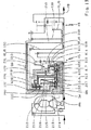
GGで表示されたギヤハウジング内でのシフトエレメントとギヤセットとの相互に関係する空間的配置に関して、DE10318565.8は次のように教える。クラッチとして形成されている第5シフトエレメントEは、空間的に見て、軸方向にプリシフトギヤセットVSとメインギヤセットHSとの間に配置されており、軸方向に直接プリシフトギヤセットVSに隣接している。同様にクラッチとして形成されている第2シフトエレメントBは、同じように軸方向にプリシフトギヤセットVSとメインギヤセットHSの間に配置されている。ただし、このクラッチBのディスクパック200は、空間的に見て、少しクラッチEのディスクパック500の径方向上方に配置されており、そしてクラッチBのサーボ装置210は、軸方向にプリシフトギヤセットVSに背いた側でクラッチEに隣接している。軸方向でメインギヤセットHS方向に見て、クラッチBには、まずブレーキとして形成されている第3シフトエレメントCが、それから同様にブレーキとして形成されている第4シフトエレメントDが、更にそれからメインギヤセットHSが隣接している。クラッチとして形成されている第1シフトエレメントAのディスクパック100は、空間的に見て、ほぼプリシフトギヤセットVSの上方に配置されている。このクラッチAのサーボ装置110は、プリシフトギヤセットVSのメインギヤセットHSに背いた側に、少なくとも大部分が配置されている。クラッチAのサーボ装置110のプリシフトギヤセットVSに背いた側、空間的に見て、軸方向にクラッチAと駆動側のギヤハウジング固定のハウジング壁GWとの間、すなわち、クラッチA及びプリシフトギヤセットVSの、メインギヤセットHSに背いた側に、クラッチとして形成された第6シフトエレメントFが配置されている。
Regarding the interrelated spatial arrangement of the shift elements and gear sets in the gear housing designated GG, DE 1031858565.8 teaches as follows. The fifth shift element E formed as a clutch is disposed between the pre-shift gear set VS and the main gear set HS in the axial direction when viewed spatially, and directly adjacent to the pre-shift gear set VS in the axial direction. ing. Similarly, the second shift element B formed as a clutch is similarly disposed between the pre-shift gear set VS and the main gear set HS in the axial direction. However, the
シフトエレメントのサーボ装置に関する実施の形態として、図1Aに、第6シフトエレメントFのサーボ装置610が詳しく記載されている。例えば、このサーボ装置610は、シリンダー形状のディスクキャリヤー内に配置されており、当該ディスクキャリヤーはクラッチFの入力エレメント620を形成し、それに応じて、常に変速機の駆動軸ANの回転数で回転する。サーボ装置610は、1つの圧力室611を有しており、当該圧力室は、クラッチFのディスクキャリヤーのシェル断片と、サーボ装置610のピストン614と、によって形成される。この圧力室611に圧力を掛けると、ピストン614が、ここでは例示的にディスクスプリングとして形成されているサーボ装置610のリターンエレメントの力に抗して、軸方向にプリシフトギヤセットVS方向に移動し、クラッチFのディスクパック600を作動するないしは閉じる。回転する圧力室611の躍動する(動的な)圧力を好適には完全に補償するために、サーボ装置610は、さらに、潤滑材で無圧で充填可能な圧力調整室612を有している。当該調整室612は、ピストン614の面とエアセンサープレート615とによって形成される。入力エレメント620は、ギヤハウジング固定のハブGN上に回転可能に取り付けられており(軸支されており)、当該ハブは、ギヤハウジング固定のハウジング壁GWから始まり、ギヤハウジングGG内で軸方向にプリシフトギヤセットVS方向にプリシフトギヤセットVSの太陽歯車SO_VSまで延伸し、この太陽歯車SO_VSと(互いに)回転しないように結合している。それに応じて、このギヤハウジング固定のハブGNは、クラッチFの圧力室ないし圧力調整室への圧力材供給用および潤滑材供給用の導路も有している。
As an embodiment relating to the servo device of the shift element, the
本発明に従う変速機のスキームないしコンポーネントの配置のための、本発明に従う以下のすべての実施の形態は、原理的には、図1Aに表示された従来技術に従う自動変速機の動的(運動機構学的)構造に基づいており、それぞれ、駆動軸ANと、出力軸ABと、当該プリシフトギヤセットのエレメントの1つを介して常に駆動軸と結合していて当該駆動軸ANの回転数より小さい出力回転数を発する、プラスの遊星歯車セットとしてダブル遊星歯車構造に形成されたプリシフトギヤセットVSと、少なくとも2つの相互に結合された遊星歯車セットで構成され少なくとも3つの独立した入力エレメント及び1つの独立した出力エレメントを有する、プリシフトギヤセットVSに対して同軸に配置されたメインギヤセットHSと、AからFまでの6つのシフトエレメントと、を有している。それらの選択的締結によって、駆動軸ANの回転数が、プリシフトギヤセットVSおよびメインギヤセットHSを介して、少なくとも前進8速がレンジシフトなしに切り替えできるというように伝達できる。このとき、プリシフトギヤセットVSの出力回転数は、第1シフトエレメントAと第2シフトエレメントBを介して、メインギヤセットHSの2つの異なる入力エレメントに伝達可能である。さらに、駆動軸ANの回転数は、第5シフトエレメントEを介してメインギヤセットHSの第3入力エレメントに伝達可能である。さらに駆動軸ANの回転数は、第6シフトエレメントFを介してメインギヤセットHSの入力エレメントに伝達可能であり、当該エレメントは第2シフトエレメントBを介してプリシフトギヤセットVSの出力エレメントと接続可能である。さらにメインギヤセットHSの出力エレメントは、常に変速機の出力軸ABと結合している。 For the arrangement of the transmission scheme or components according to the invention, all the following embodiments according to the invention are in principle the dynamic (motion mechanism) of the automatic transmission according to the prior art shown in FIG. Each of which is always coupled to the drive shaft via the drive shaft AN, the output shaft AB and one of the elements of the pre-shift gear set and is less than the rotational speed of the drive shaft AN, respectively. A pre-shift gear set VS formed in a double planetary gear structure as a positive planetary gear set for generating output rotational speed, and at least three independent planetary gear sets composed of at least two mutually connected planetary gear sets and one A main gear set HS with an independent output element and arranged coaxially with the pre-shift gear set VS, and A to F It has six shift elements, the at. By these selective engagements, the rotational speed of the drive shaft AN can be transmitted through the pre-shift gear set VS and the main gear set HS so that at least the eighth forward speed can be switched without a range shift. At this time, the output rotation speed of the pre-shift gear set VS can be transmitted to two different input elements of the main gear set HS via the first shift element A and the second shift element B. Furthermore, the rotational speed of the drive shaft AN can be transmitted to the third input element of the main gear set HS via the fifth shift element E. Furthermore, the rotational speed of the drive shaft AN can be transmitted to the input element of the main gear set HS via the sixth shift element F, which can be connected to the output element of the pre-shift gear set VS via the second shift element B. It is. Further, the output element of the main gear set HS is always coupled to the output shaft AB of the transmission.
図2から8に表示された、本発明に従う最初の7つの異なる変速機のスキームは、1つには、図1Aに表示されたメインギヤセットHSのギヤセットタイプすなわちラビニヨ式メインギヤセットHSに、もう1つには、これも基本的に図1Aで表示された変速機内のギヤセットおよびシフトエレメントのコンポーネントの配置に、基づいている。 The first seven different transmission schemes according to the present invention shown in FIGS. 2 to 8 include, in part, a gear set type of the main gear set HS shown in FIG. 1A, namely a Ravigneaux main gear set HS. For one thing, this is also basically based on the arrangement of the gearset and shift element components in the transmission as shown in FIG. 1A.
図2に基づいて、これより、本発明に従う第1の例示的な変速機のスキームを、図1Aに表示された従来技術に従う変速機のスキームに基づいて、説明する。図2から容易に分かるように、駆動軸AN及び当該駆動軸ANと同軸に配置されている出力軸ABと、プラスの遊星歯車セットとしてダブル遊星歯車構造に形成されているプリシフトギヤセットVSと、プリシフトギヤセットVSに対して同軸に配置されていて、結合された2キャリヤー4軸遊星ギヤとして2つの太陽歯車S1_HS、S2_HS及び唯一の内歯歯車HO_HSを有するラビニヨ式ギヤセット構造で形成されているメインギヤセットHSと、駆動軸ANの回転数をプリシフトギヤセットVS及びメインギヤセットHSを介して出力軸ABに伝達するための、6つの選択的な対(組)によってシフト可能なAからFまでのシフトエレメントと、を備えた変速機の動的構造は、図1Aからそっくり引き継がれた。従って、図1Aでのように、プリシフトギヤセットVSの太陽歯車SO_VSは、ギヤハウジングGGに固定されており、プリシフトギヤセットVSの結合されたキャリヤーST_VSは、変速機の駆動軸ANと回転しないように常に結合されており、これによって、プリシフトギヤセットVSの内歯歯車HO_VSは、駆動軸ANの回転数に対して、プリシフトギヤセットVSの減速された出力回転数を発する。従って、図1Aでのように、メインギヤセットHSの第1太陽歯車S1_HSは、その第1入力エレメントを形成し、当該エレメントは、クラッチBを介してプリシフトギヤセットVSの内歯歯車HO_VSと、またクラッチFを介して駆動軸ANと結合可能であり、そしてブレーキCを介してギヤハウジングGGに固定できる。またメインギヤセットHSの第2太陽歯車S2_HSは、その第2入力エレメントを形成し、当該エレメントは、クラッチAを介してプリシフトギヤセットVSの内歯歯車HO_VSと結合可能である。またメインギヤセットHSの結合されたキャリヤーST_HSは、その第3入力エレメントを形成し、当該エレメントは、クラッチEを介して駆動軸ANと結合可能であり、そしてブレーキDを介してギヤハウジングGGに固定できる。またメインギヤセットHSの唯一の内歯歯車HO_HSは、その出力エレメントを形成し、当該エレメントは、常に出力軸ABと回転しないように結合されている。考えられるメインギヤセットHSのもう1つの実施の形態については、後でさらに詳しく説明する。 Based on FIG. 2, a first exemplary transmission scheme according to the present invention will now be described based on the prior art transmission scheme displayed in FIG. 1A. As can be easily seen from FIG. 2, the drive shaft AN, the output shaft AB arranged coaxially with the drive shaft AN, a pre-shift gear set VS formed in a double planetary gear structure as a positive planetary gear set, A main gear which is arranged coaxially with the pre-shift gear set VS and has a Ravigneaux type gear set structure having two sun gears S1_HS, S2_HS and a single internal gear HO_HS as a coupled two-carrier four-axis planetary gear Shift from A to F which can be shifted by six selective pairs (sets) for transmitting the set HS and the rotational speed of the drive shaft AN to the output shaft AB via the pre-shift gear set VS and the main gear set HS The dynamic structure of the transmission with the elements was taken over from FIG. 1A. Accordingly, as shown in FIG. 1A, the sun gear SO_VS of the preshift gear set VS is fixed to the gear housing GG, and the carrier ST_VS coupled to the preshift gear set VS does not rotate with the drive shaft AN of the transmission. As a result, the internal gear HO_VS of the preshift gear set VS generates a reduced output rotational speed of the preshift gear set VS with respect to the rotational speed of the drive shaft AN. Accordingly, as in FIG. 1A, the first sun gear S1_HS of the main gear set HS forms its first input element, which is connected to the internal gear HO_VS of the pre-shift gear set VS via the clutch B, and It can be coupled to the drive shaft AN via the clutch F and can be fixed to the gear housing GG via the brake C. The second sun gear S2_HS of the main gear set HS forms the second input element, and this element can be coupled to the internal gear HO_VS of the pre-shift gear set VS via the clutch A. The carrier ST_HS coupled to the main gear set HS forms a third input element that can be coupled to the drive shaft AN via the clutch E and is fixed to the gear housing GG via the brake D. it can. The only internal gear HO_HS of the main gear set HS forms its output element, and this element is always coupled to the output shaft AB so as not to rotate. Another possible embodiment of the main gear set HS will be described in more detail later.
図2から、変速機内のギヤセット及びシフトエレメントのコンポーネントの配置も、基本的に図1Aから引き継がれたことが容易に分かる。図1Aとの相違は、プリシフトギヤセットVSのメインギヤセットから遠い側で、軸方向にギヤハウジング固定のハウジング壁GWの横で、径方向にギヤハウジング固定のハブGNの上方に配置されている第6シフトエレメントFのクラッチシリンダーの動的結合に関係している。当該クラッチシリンダーの中には、クラッチFのディスクパック600及びこのディスクパック600を作動させるためのサーボ装置610が配置されている。図1Aでこのクラッチシリンダーが駆動軸ANと回転しないように結合されたクラッチFの入力エレメントをさらに形成していたら、このクラッチシリンダーは、図2ではクラッチFの出力エレメント630を形成する。当該エレメントは、クラッチFの既定の動的結合に対応して、メインギヤセットHSの第1太陽歯車S1_HS−ここでは例示的にメインギヤセットHSの第1入力エレメントを形成している−と回転しないように結合している。これによって、クラッチFのサーボ装置610は、常にこの第1太陽歯車S1_HSの回転数で回転する。
From FIG. 2, it can be easily seen that the arrangement of the gear set and shift element components in the transmission has basically been taken over from FIG. 1A. The difference from FIG. 1A is that the pre-shift gear set VS is far from the main gear set, beside the housing wall GW fixed in the axial direction in the axial direction, and above the hub GN fixed in the radial direction in the radial direction. 6 relates to the dynamic coupling of the clutch cylinder of the shift element F. In the clutch cylinder, a
図1Aでのように、クラッチEは、軸方向にプリシフトギヤセットVSに、そのメインギヤセットHSに向いた側で隣接している。クラッチEの入力エレメント520は、プリシフトギヤセットVSの結合されたキャリヤーST_VSのメインギヤセットに近いキャリヤープレートと、駆動軸ANと、に結合しており、例示的に、クラッチEのディスクパック500の外側噛合いディスクを収容するためのアウターディスクキャリヤーとして形成されている。クラッチEの出力エレメント530は、例示的に、クラッチEのディスクパック500の内側噛合いディスクを収容するための大部分がディスク形状のインナーディスクキャリヤーとして形成されており、キャリヤーシャフト540を介して、メインギヤセットHSの結合されたキャリヤーST_HS−ここでは例示的にメインギヤセットHSの第3入力エレメントを形成している−と回転しないように結合しており、キャリヤーシャフト540は、メインギヤセットHSを軸方向に中心で貫いている。クラッチEのディスクパック500は、例示的に、プリシフトギヤセットVSの内歯歯車HO_VSの直径領域内に配置されている。(図2では簡略化のために単に図式的に表示されている)サーボ装置510に属するディスクパック500を作動させるためのサーボ装置510は、シリンダールーム内に配置されており、当該シリンダールームは、クラッチEの入力エレメント520ないしアウターディスクキャリヤーによって形成される。クラッチEの締結時にこのサーボ装置510は、それに属するディスクパック500を軸方向にメインギヤセットHS方向に作動させる。実務上は、このサーボ装置510は、常に駆動軸ANの回転数で回転するために、動的圧力調整装置も有する。
As shown in FIG. 1A, the clutch E is adjacent to the pre-shift gear set VS in the axial direction on the side facing the main gear set HS. The
図1Aでのように、クラッチAのディスクパック100は、径方向にプリシフトギヤセットVSの上方の領域に配置されている。プリシフトギヤセットVSの内歯歯車HO_VSと回転しないように結合している、クラッチAの入力エレメント120は、例示的に、このディスクパック100の外側噛合いディスクを収容するためのアウターディスクキャリヤーとして形成されており、そのシリンダールーム内に、ディスクパック100を作動させるための(図2では簡略化のために単に図式的に表示されている)サーボ装置110を擁しており、このサーボ装置110は、空間的に見て、プリシフトギヤセットVSのメインギヤセットHSとは逆の側に大部分が配置されており、当該サーボ装置に属するディスクパック100をクラッチAの締結時に軸方向にメインギヤセットHS方向に作動させる。実務上は、このサーボ装置110は、常にプリシフトギヤセットVSの内歯歯車HO_VSの回転数で回転するために、動的圧力調整装置も有する。クラッチAの出力エレメント130は、例示的に、クラッチAのディスクパック100の内側噛合いディスクを収容するためのシリンダー形状のインナーディスクキャリヤーとして形成されており、クラッチEを径方向に包囲し、そして第2太陽軸140を介して、メインギヤセットHSのプリシフトギヤセットから遠い第2太陽歯車S2_HS−ここでは例示的にメインギヤセットHSの第2入力エレメントを形成している−と回転しないように結合されている。このとき、この第2太陽軸140は、少なくとも、メインギヤセットHSのプリシフトギヤセットに近い第1太陽歯車S1_HSを中心で軸方向に貫き、キャリヤーシャフト540を包囲する。好ましくは、第2太陽軸140は、キャリヤーシャフト540にも回転可能に取り付けられる。
As shown in FIG. 1A, the
図1Aでのように、クラッチBのディスクパック200は、径方向にクラッチEの上方の範囲に配置されている。クラッチAの入力エレメント120ないしアウターディスクキャリヤーと回転しないように結合されている、クラッチBの入力エレメント220は、例示的に、クラッチBのディスクパック200の内側噛合いディスクを収容するためのインナーディスクキャリヤーとして形成されている。空間的に見て、クラッチBの入力エレメント220ないしインナーディスクキャリヤーと、径方向内側にあるクラッチEの入力エレメント520ないしアウターディスクキャリヤーの外径と、の間を、クラッチAの出力エレメント130ないしインナーディスクキャリヤーのシリンダー形状部が、径方向に走っている(延びている)。それに対応して、クラッチBの出力エレメント230は、クラッチBのディスクパック200の外側噛合いディスクを収容するためのアウターディスクキャリヤーとして形成されている。クラッチBのこの出力エレメント230は、幾何学的には、プリシフトギヤセットVS方向に向かって開かれた深い容器状に形成されており、第1太陽軸240を介して、プリシフトギヤセットに近いメインギヤセットHSの第1太陽歯車S1_HS−ここでは例示的にメインギヤセットHSの第1入力エレメントを形成している−と回転しないように結合されている。この第1太陽軸240は、第2太陽軸140の一部分を径方向に包囲し、そして好ましくは、この第2太陽軸140にも回転可能に取り付けられている。例えば、出力エレメント230のハブと太陽軸240のハブは、一体に形成されていてもよい。そのシリンダールーム内で、クラッチBの出力エレメント230なしアウターディスクキャリヤーが、クラッチBのディスクパック200を作動させるための(図2では簡略化のために単に図式的表示されている)サーボ装置210を擁しており、この場合、このサーボ装置210は、空間的に見て、ディスクパック200の、メインギヤセットHSに向いた側に配置されており、軸方向にクラッチAの出力エレメント130ないしインナーディスクキャリヤーのディスク形状部分に隣接している。クラッチBの締結時にこのサーボ装置210が当該サーボ装置に属するディスクパック200を軸方向にプリシフトギヤセットVS方向に作動させる。実務上は、このサーボ装置210は、常にメインギヤセットHSの第1太陽歯車S1_HSの回転数で回転するために、動的圧力調整装置も有する。
As shown in FIG. 1A, the
すでに述べたように、クラッチFの出力エレメント630は、クラッチFのディスクパック600の外側噛合いディスクを収容するためのアウターディスクキャリヤーとして形成されており、空間的に見て、ここでは例示的にギヤハウジングGGの外壁を形成するギヤハウジング固定のハウジング壁GWに隣接していて、当該ハウジング壁は、図2では詳しく描写されていない変速機の駆動エンジンに向いており、この駆動エンジンは、ここでは例示的にトルクコンバーターを介して駆動軸ANと作用結合している。その限りでは、ギヤハウジング固定のハブGNは、ハウジング壁GWから始まって、変速機内部で軸方向にプリシフトギヤセットVS方向に延伸し、そしてそこにはプリシフトギヤセットVSの太陽歯車SO_VSが固定されており、径方向にその上方にクラッチFも配置されているが、このトルクコンバーターのステータシャフト(Leitradwelle)でもあり得る。クラッチFの出力エレメント630ないしアウターディスクキャリヤーは、幾何学的には、プリシフトギヤセットVSないしメインギヤセットHS方向に向かって開かれた深い容器として形成されており、ハブ633、ディスク形状の容器底632、そして曲折したシリンダー形状部分631を有する。クラッチFの出力エレメント630ないしアウターディスクキャリヤーのハブ633は、ギヤハウジング固定のハブGN上に回転可能に取り付けられている。このハブ633に接続する、クラッチFの出力エレメント630ないしアウターディスクキャリヤーのディスク形状の容器底632は、ハウジング壁GWに隣接して並行に径方向外側に延伸し、クラッチFの出力エレメント630ないしアウターディスクキャリヤーの曲折したシリンダー形状部分631における外径を超えている。この曲折したシリンダー形状部分631は、軸方向にプリシフトギヤセットVS方向に、ここでは例示的にギヤハウジング固定のハブGNのほぼ中央にまで延伸し、そのプリシフトギヤセットに近い端部の範囲の内径に、クラッチFのディスクパック600のアウターディスクを収容するための受容部(Mitnahmeprofil)を有している。
As already described, the
圧力室611、圧力調整室612、ピストン614、リターンエレメント613、及び、エアセンサープレート615を有する、クラッチFのサーボ装置610は、完全にシリンダールーム内に配置されている。当該シリンダールームは、クラッチFの出力エレメント630ないしアウターディスクキャリヤーによって形成され、基本的に径方向にハブ633の上方に配置されている。ピストン614は、クラッチFの出力エレメント630ないしアウターディスクキャリヤーに軸方向に移動可能に取り付けられている。それに応じて、サーボ装置610は、常時、メインギヤセットHSの第1入力エレメント(つまり、ここでは第1太陽歯車S1_HS)の回転数で回転する。サーボ装置610の回転する圧力室611の回転圧を調整するために、潤滑材を無圧で充填できる圧力調整室612を備えた動的な圧力調整装置が設けられている。この場合、この圧力調整室612は、上記圧力室611よりもプリシフトギヤセットVS(ないしはメインギヤセットHS)の近くに配置されている。このとき、圧力室611は、ピストン614と、クラッチFの出力エレメント630ないしアウターディスクキャリヤーのシェルと、によって形成される。圧力調整室612は、ピストン614とエアセンサープレート615とによって形成される。当該エアセンサープレートは、軸方向にハブ633のプリシフトギヤセットに近い端部に固定されており、ピストン614に対しては、軸方向に移動可能で潤滑材が漏れないように密封されている。ピストン614には、ここで例示的にディスクスプリングとして形成されているリターンエレメント613を介して、軸方向にクラッチFの出力エレメント630ないしアウターディスクキャリヤーのハブ633に対して初期張力が与えられている。クラッチFを締結するために圧力室611を圧力材で加圧すると、ピストン614は軸方向にプリシフトギヤセットVS(ないしメインギヤセットHS)方向に移動し、前記ピストンに属するディスクパック600をリターンエレメント613のスプリング力に抗して作動させる。
The
クラッチFの出力エレメント630ないしアウターディスクキャリヤーが、ギヤハウジング固定のハブGN上に取り付けられているために、部分的に上記ハウジングハブGN内を走り、部分的にクラッチFの出力エレメント630のハブ633内を走る導路や孔(ホール)によって、構造的に比較的簡単なクラッチFへの圧力材や潤滑材を供給する装置が生じる。クラッチFのサーボ装置610の圧力室611への圧力材供給装置は616で表示され、サーボ装置610の圧力調整室612への潤滑材供給装置は617で表示されている。
Since the
クラッチFの出力エレメント630ないしアウターディスクキャリヤーと、メインギヤセットHSの第1太陽歯車S1_HSと、の間の回転数およびトルク伝達は、シリンダー形状の結合エレメントZYL、クラッチBの出力エレメント230ないしアウターディスクキャリヤー、及び、軸方向のショートの(短い)第2太陽軸140を介して行われる。このシリンダー形状の結合エレメントZYLは、幾何学的には、ハウジング壁GW方向に向かって開かれた深い容器状に形成されており、ディスク形状の容器底とシリンダー形状のシェルとを備えている。当該シェルは、軸方向におけるプリシフトギヤセットVSとクラッチAとを径方向に完全に網羅している。結合エレメントZYLの容器底は、その内径の、クラッチBのディスクパック200の範囲で、クラッチBの出力エレメント230ないしアウターディスクキャリヤーと回転しないように結合されている。上記容器底の外径に接続する、結合エレメントZYLのシリンダー形状のシェルは、軸方向にハウジング壁GW方向にクラッチFのディスクパック600まで延伸し、そしてこの範囲(領域)でクラッチFの出力エレメント630ないしアウターディスクキャリヤーと回転しないように、例えば受容部(Mitnahmeprofil)を介して、結合されている。
The rotational speed and torque transmission between the
アウターディスクキャリヤーとしてのクラッチFの出力エレメント630の形成に対応して、動的に駆動軸ANと結合されるクラッチFの入力エレメント620は、クラッチFのディスクパック600の内側噛合いディスクを収容するためのインナーディスクキャリヤーとして形成されている。図2に表示された実施の形態では、クラッチFのこの入力エレメント620は、ハブ623を有し、当該ハブは空間的に見て、軸方向にクラッチFの出力エレメント630のハブ633とプリシフトギヤセットVSの太陽歯車SO_VSとの間の領域で、径方向にギヤハウジング固定のハブGNの上に回転可能に取り付けられて(支持されて)いる。クラッチFの入力エレメント620のこのハブ623は、そのプリシフトギヤセットに近い側で、プリシフトギヤセットVSの結合されたキャリヤーST_VSのメインギヤセットから遠いキャリヤープレートと回転しないように結合されている。このキャリヤーST_VSは、そのメインギヤセットに近いキャリヤープレートを介して、駆動軸ANと回転しないように結合されている。クラッチAの入力エレメント120のハブ123は、クラッチFの入力エレメント620のハブ623の上に回転可能に支持されており、クラッチAの入力エレメント120のこのハブ123は、そのプリシフトギヤセットに近い側で、軸方向にキャリヤーST_VSのメインギヤセットから遠いキャリヤープレートに隣接している受容ディスク(Mitnahmescheibe)150を介して、プリシフトギヤセットVSの内歯歯車HO_VSと回転しないように結合されている、ということがこの場でさらに言及される。
Corresponding to the formation of the
図1Aでのように、ブレーキCは、例示的に、ディスクブレーキとしてディスクパック300とともに形成されている。このディスクパック300は、空間的に見て、径方向にクラッチBの出力エレメント230ないしアウターディスクキャリヤーの容器底の上方に配置されており、クラッチBのディスクパック200とほぼ同じ直径上(径方向位置)に配置されている。ブレーキCのディスクパック300の内側噛合いディスクを収容するためのインナーディスクキャリヤーとして形成されている、ブレーキCの出力エレメント330は、図1Aでのように、クラッチBの出力エレメント230ないしアウターディスクキャリヤーと、その容器底の範囲で、回転しないように結合されており、そしてこの出力エレメント230を介してメインギヤセットHSの第1太陽歯車S1_HSと結合している。図1Aでのように、同様に例示的にディスクブレーキとしてディスクパック400とともに形成されているブレーキDは、メインギヤセットHS方向に見て、軸方向にブレーキCに接続している。この場合、ディスクパック400の内側噛合いディスクを収容するためのインナーディスクキャリヤーとして形成されている、このブレーキDの出力エレメント430は、メインギヤセットHSのプリシフトギヤセットVSに向いた側で、メインギヤセットHSの結合されたキャリヤーST_HS−ここでは例示的にメインギヤセットHSの第3入力エレメントを形成している−と回転しないように結合されている。図2に表示された実施の形態では、2つのブレーキC及びDのアウターディスクキャリヤーは、ギヤハウジングGG内で一体化されているが、もちろん、別々のコンポーネントとして形成されていてもよく、その場合は、それらは、ギヤハウジングに回転しないように結合される。図2では、ブレーキCのサーボ装置310がディスクパック300を作動させること、そしてブレーキDのサーボ装置410がディスクパック400を作動させること、が暗示されている。この場合、この2つのサーボ装置310、410は、ここでは例示的に軸方向にディスクパック300と400との間に配置されている。もちろん、ブレーキC及び/またはブレーキDは、バンドブレーキとして形成されていてもよい。図2に従う変速機のスキームが非同軸の駆動及び出力に関して変更される場合、当業者(専門家)はブレーキDを、図2と異なり、メインギヤセットHSのプリシフトギヤセットVSとは逆の側に配置するであろう。特にこのような非同軸の駆動及び出力の場合、ブレーキCに関しても、図2とは異なる空間的位置がギヤハウジングGG内で考えられる。すなわち、軸方向ではハウジング壁GWに隣接し、径方向にクラッチFのアウターディスクキャリヤー630の曲折した部分の上方、そして、径方向にクラッチFのサーボ装置610の圧力室611の上方、である。
As shown in FIG. 1A, the brake C is illustratively formed with the
図3に基いて、本発明に従う第2の実施の形態の変速機のスキームを説明する。前の図2を基にして説明された本発明に従う第1の実施の形態のスキームとの相違は、クラッチFの出力エレメント630の構造上の形態と、クラッチFのディスクパック600を作動させるためのサーボ装置610の構造上の形態と、に関している。その限りにおいて、図3の説明は、この本質的なコンポーネントに限定して留めることができる。
Based on FIG. 3, the scheme of the transmission of the second embodiment according to the present invention will be described. The difference from the scheme of the first embodiment according to the present invention described above with reference to FIG. And the structural form of the
図3から分かるように、シリンダー形状の結合エレメントZYLとクラッチBの出力エレメント230とを介してプリシフトギヤセットに近いメインギヤセットHSの第1太陽歯車S1_HSに結合されたクラッチFの出力エレメント630は、ここでは、クラッチFのディスクパック600の内側噛合いディスクを収容するためのインナーディスクキャリヤーとして形成されている。図2でのように、この出力エレメント630は、この場合、プリシフトギヤセットVSのメインギヤセットHSとは逆の側でギヤハウジングGGの外壁を形成するギヤハウジング固定のハウジング壁GWに隣接しており、そのハブ633と共に、このハウジング壁GWから始まって変速機内部でプリシフトギヤセットVSの太陽歯車SO_VSまで延伸するギヤハウジング固定のハブGN上に回転可能に取り付けられており、そして、クラッチFのサーボ装置610を収容している。それに応じて、プリシフトギヤセットVSの結合されたキャリヤーST_VSを介して駆動軸ANと結合されたクラッチFの入力エレメント620は、ここでは、クラッチFのディスクパック600の外側噛合いディスクを収容するためのアウターディスクキャリヤーとして形成されている。図2でのように、この入力エレメント620のハブ623は、同様に、ギヤハウジング固定のハブGN上に回転可能に取り付けられており、しかも、軸方向にプリシフトギヤセットVSと上記ハブGN上の出力エレメント630の径方向の支持部との間の範囲にある。同様に図2でのように、クラッチシリンダーとして、クラッチAのディスクパック100と、このディスクパック100を作動させるためのサーボ装置110と、を収容するクラッチAの入力エレメント120は、本質的に、クラッチFとプリシフトギヤセットVSとの間に配置されている。クラッチAのディスクパック100は、軸方向の範囲でプリシフトギヤセットVSの上方に配置されているが、入力エレメント120のハブ123は、プリシフトギヤセットVSのクラッチFに向いた側で、クラッチFの入力エレメント620のハブ623に取り付けられている。
As can be seen from FIG. 3, the
図3からさらに分かるように、クラッチFの出力エレメント630ないしインナーディスクキャリヤーは、基本的にシリンダー形状の構造を有しており、上述したようにギヤハウジング固定のハブGN上に回転可能に取り付けられているハブ633と、上記ハブ633から始まって、軸方向に隣接し、例示的に大部分がハウジング壁GWに並行に径方向外側に向かって延伸するディスク形状部分と、クラッチFの出力エレメント630ないしインナーディスクキャリヤーの上記ディスク形状部分の外径から始まって、軸方向にプリシフトギヤセットVS方向にクラッチFのディスクパック600まで延伸している段付きシリンダー形状部分と、を備えている。クラッチFの出力エレメント630ないしインナーディスクキャリヤーのこの段付きシリンダー形状部分は、そのプリシフトギヤセットに近い端部の範囲において、上記ディスクパック600のインナーディスクを収容するための適切な受容部(Mitnahmeprofil)を外径に有している。クラッチFの出力エレメント630ないしインナーディスクキャリヤーのハウジング壁に近い端部の範囲において、径方向でクラッチFの出力エレメント630ないしインナーディスクキャリヤーのディスク形状部分のほぼ上方に、シリンダー形状の支持プレート618が、その内径で、クラッチFの出力エレメント630ないしインナーディスクキャリヤーの段付きディスク形状部分の外径に回転しないように固定されている。この支持プレート618のディスク形状部分は、クラッチFの出力エレメント630ないしインナーディスクキャリヤーの外径から始まって、例示的に大部分がハウジング壁GWに並行に、径方向外側に向かってクラッチFのディスクパック600のほぼ外径にまで延伸し、それからシリンダー形状部分に移行して、軸方向にプリシフトギヤセットVS方向にクラッチFのディスクパック600の少し前まで延伸する。
As can be further understood from FIG. 3, the
圧力室611、圧力調整室612、ピストン614、リターンエレメント613、を有する、クラッチFのサーボ装置610は、空間的に見て、径方向にクラッチFの出力エレメント630ないしインナーディスクキャリヤーの段付きシリンダー形状部分の上方に配置されている。軸方向にクラッチFのディスクパック600と支持プレート618のディスク形状部分との間に配置されているピストン614は、このとき、支持プレート618のシリンダー形状部の内径と、クラッチFの出力エレメント630ないしインナーディスクキャリヤーの外径と、の間に出来ているリングルームの中で、圧力材を漏らさないように軸方向に移動可能に取り付けられている。圧力室611を形成するために、支持プレート618とクラッチFの出力エレメント630ないしインナーディスクキャリヤーとの間のトルク誘導結合が、圧力材を漏らさないように形成されている。その結果、圧力室611は、ピストン614、支持プレート618の内側シェル、そしてクラッチFの出力エレメント630ないしインナーディスクキャリヤーの外側シェルの部分、によって形成される。ここで、常に太陽歯車S1_HSの回転数で回転する圧力室611の回転圧を調整するために、潤滑材供給装置617を介して無圧で潤滑材を充填できる圧力調整室612が、ピストン614の圧力室611の逆の側に配置されている。この圧力調整室612は、ピストン614と、ピストン614に対して潤滑材を漏らさないように軸方向に移動可能に密閉された、クラッチFの出力エレメント630ないしインナーディスクキャリヤーの段付きシリンダー形状部分の外側シェル部分と、によって形成される。圧力室611が、クラッチFを締結するために、圧力材供給装置616を介して圧力材で満たされると、ピストン614は、ここでは例示的にリング形状でピストン614の周囲に分散して配置され動的に並置されたコイルスプリングからなるパック(セット)として形成され軸方向にピストン614とクラッチFの出力エレメント630ないしインナーディスクキャリヤーとの間に装着されているリターンエレメント613の復元力に抗して、軸方向にプリシフトギヤセットVS方向に移動し、そして当該ピストンに属するクラッチFのディスクパック600を作動させる。
The
クラッチFの出力エレメント630ないしインナーディスクキャリヤーと、シリンダー形状の結合エレメントZYLと、の間の回転数及びトルク伝達は、図3に表示された本発明に従う変速機の実施の形態では、クラッチFの支持プレート618を介して行われる。支持プレート618は、一方で、このために−前述のように−その内径にクラッチFの出力エレメント630ないしインナーディスクキャリヤーの段付きシリンダー形状部分に対しての適切なトルク誘導の結合具(結合部)を有している。他方、支持プレート618は、このためにそのシリンダー形状部のディスクに近い端部の範囲内において、適切な結合具を介して、上記結合エレメントZYLのハウジング壁側の端部と、例えば受容部(Mitnahmeprofil)を介してインターロック式(formschluessig)に、回転しないように結合されている。このとき、シリンダー形状の結合エレメントZYLは、その軸方向の移行の中で2つのクラッチA及びFのディスクパック100,600を網羅する(包括する)。むしろ、クラッチBの出力エレメント230と結合エレメントZYLとの一体の形成を物語る図3の表示に対し、クラッチFの入力エレメント620ないしアウターディスクキャリヤー及びクラッチBの出力エレメント230ないしアウターディスクキャリヤーの幾何学的な設計に応じて、支持プレート618と結合エレメントZYLとが一体に形成される、ということも考慮され得る。
The rotational speed and torque transmission between the
図4に基づいて、ここでは、本発明に従う第3の実施の形態の変速機のスキームを、図2に表示された第1の実施の形態に基づいて説明する。図4から分かるように、クラッチFは、図2に対して軸方向に同じように形成されている。クラッチFのディスクパック600の内側噛合いディスクを収容するためのインナーディスクキャリヤーとして形成されているクラッチFの入力エレメント620は、ここでは、プリシフトギヤセットVS方向に向かって開かれたシリンダーとして形成されている。当該入力エレメント620は、ギヤハウジング固定のハウジング外壁GWとプリシフトギヤセットVSとの間で軸方向に延伸するギヤハウジング固定のハブGNをほぼその軸方向の全長で径方向に包囲すると共に当該ハブGNに回転可能に取り付けられているハブ623と、上記ハブ623のハウジング壁側の端部で接続して軸方向に直に且つここでは例示的にハウジング壁GWに基本的に並行に径方向外側に向かってクラッチFのディスクパック600のほぼ直径にまで延伸するディスク形状部分622と、上記ディスク形状部分622の外径で接続して軸方向にプリシフトギヤセットVS方向にクラッチFのディスクパック600のプリシフトギヤセット側の端部まで延伸するシリンダー形状部分621と、を備えている。クラッチFの入力エレメント620の上記シリンダー形状部分621は、その外径に、このディスクパック600のインナーディスクを収容するための適切な受容部を有している。クラッチFの入力エレメント620のハブ623は、そのプリシフトギヤセットに近い端部で、プリシフトギヤセットVSの結合されたキャリヤーST_VSのメインギヤセットから遠いキャリヤープレートと回転しないように結合されており、これによって、このキャリヤーST_VSを介して駆動軸ANと結合されている。
Based on FIG. 4, here, the scheme of the transmission of the third embodiment according to the present invention will be described based on the first embodiment displayed in FIG. As can be seen from FIG. 4, the clutch F is formed in the same axial direction with respect to FIG. The
図2でのように、プリシフトギヤセットVSの内歯歯車HO_VSと結合しているクラッチAの入力エレメント120は、この入力エレメント120の中に配置されているクラッチAのサーボ装置110とともに、ハウジング外壁GWに向いたメインギヤセットHSとは逆の側にあるプリシフトギヤセットVS側に、基本的に配置されている。このとき、クラッチAのディスクパック100は、例示的に、径方向にプリシフトギヤセットVSの上方の範囲に配置されている。この場合、クラッチAのこの入力エレメント120のハブ123は、クラッチFの入力エレメント620のハブ623の上に回転可能に取り付けられており、そのプリシフトギヤセットに近い側でプリシフトギヤセットVSの内歯歯車HO_VSと回転しないように結合されている。
As shown in FIG. 2, the
クラッチFのディスクパック600の外側噛合いディスクを収容するためのアウターディスクキャリヤーとして形成されているクラッチFの出力エレメント630は、ここでは、ハウジング外壁GW方向ないしはプリシフトギヤセットVSとは逆の方向に向かって開かれたシリンダーとして形成されており、ハウジング外壁GWに向いたないしはプリシフトギヤセットVSとは逆の、クラッチAの入力エレメントの側に配置されている。クラッチFの出力エレメント630ないしアウターディスクキャリヤーのハブ633は、空間的に見て、軸方向にクラッチFの入力エレメント620ないしインナーディスクキャリヤーのディスク形状部分622と、クラッチAの入力エレメント120のハブ123と、の間に配置されており、クラッチFの入力エレメント620ないしインナーディスクキャリヤーのハブ623のハウジング壁に近い部分を径方向に包囲し、当該ハブ623の上に回転可能に取り付けられている。クラッチFの出力エレメント630ないしアウターディスクキャリヤーの広範囲なディスク形状部分632は、クラッチFの出力エレメント630ないしアウターディスクキャリヤーの上記ハブ633のプリシフトギヤセットに近い端部に接続しており、軸方向にクラッチAの入力エレメント120に隣接して径方向外側に、クラッチFのディスクパック600の外径より大きくそしてクラッチAの入力エレメント120ないしアウターディスクキャリヤーの外径より大きい直径にまで、延伸している。クラッチFの出力エレメント630ないしアウターディスクキャリヤーのシリンダー形状部分631は、クラッチFの出力エレメント630ないしアウターディスクキャリヤーの上記ディスク形状部分632の外径に接続しており、軸方向にハウジング壁GW方向にクラッチFのディスクパック600を超えてすれすれまで延伸している。このディスクパック600の範囲には、クラッチFの出力エレメント630ないしアウターディスクキャリヤーの上記シリンダー形状部分631が、その内径に、このディスクパック600のアウターディスクを収容するための適切な受容部を有している。そのプリシフトギヤセットに近い端部で、クラッチFの出力エレメント630ないしアウターディスクキャリヤーの上記シリンダー形状部分631が、その外径の領域でシリンダー形状の結合エレメントZYLと、回転しないように結合されている。径方向でクラッチAの入力エレメント120の上方を、軸方向に走る(延びる)この結合エレメントZYLは、図2でのように、クラッチFの出力エレメント630と、クラッチBの出力エレメント230と、の間の動的結合のために設けられており、この場合、クラッチBのこの出力エレメント230は、さらにブレーキCの出力エレメント330と、そしてメインギヤセットHSの第1入力エレメント−つまり、ここでは第1太陽歯車S1_HS−と、結合している。
The
クラッチFのディスクパック600を作動させるためのサーボ装置610は、完全にシリンダールームの中に配置されている。当該シリンダールームは、クラッチFの出力エレメント630ないしアウターディスクキャリヤーによって形成され、空間的に見て、径方向ではこの出力エレメント630のハブ633の上方に位置している。通常のように、このサーボ装置610は、圧力材を充填可能な圧力室611と、当該圧力室611の回転圧を動的に圧力調整するための、無圧で潤滑材が充填可能な圧力調整室612と、ディスクパック600に作用するピストン614と、例示的にディスクスプリングとして形成されている、ピストンを復帰させるためのリターンエレメント613と、圧力調整室612を形成するためのエアセンサープレート615と、を有している。ピストン614は、図2での場合と同様に、クラッチFの出力エレメント630の中に軸方向に移動可能に取り付けられており、そのとき、これに対して圧力材が漏れないよう密閉されている。これに応じて、サーボ装置610は、常にメインギヤセットHSの第1入力エレメントの回転数で回転する。図2と異なり、ピストン614と出力エレメント630の内側シェルとによって形成されるサーボ装置610の圧力室611は、ピストン614と、ピストン614に対向して軸方向に移動可能で潤滑材が漏れないよう密閉されたエアセンサープレート615と、によって形成されるサーボ装置610の圧力調整室612より、プリシフトギヤセットVSの近くに配置されている。図2と異なり、サーボ装置610のピストン614は、圧力室611を加圧すると、軸方向にハウジング壁GW方向にないしは軸方向にプリシフトギヤセットVSとは逆の方向に、リターンエレメント613のスプリング力に抗して移動し、そして当該ピストンに属するクラッチFのディスクパック600を作動させる。
The
図2との相違について、クラッチFへの圧力材及び潤滑材の供給は、部分的にギヤハウジング固定のハブGN内を走り、部分的にクラッチFの入力エレメント620のハブ623内を走り、そして部分的にクラッチFの出力エレメント630のハブ633内を走る導路や孔(ホール)を介して行われる。図4では、該当する圧力材供給装置は616で表示され、該当する潤滑材供給装置は617で表示される。
With respect to the difference from FIG. 2, the supply of pressure and lubricant to the clutch F runs partially in the gear housing fixed hub GN, partially in the
その他のギヤコンポーネントは、変速機内でのその構造的形成及びその配置に関して、図2から引き継がれているために、この場でのそれらの再度の説明は省略することができる。 Since the other gear components have been taken over from FIG. 2 with regard to their structural formation and their arrangement in the transmission, their re-explanation here can be omitted.
図5は、本発明に従う第4の実施の形態の変速機のスキームを示している。当該変速機のスキームは、前の図4に表示された、本発明に従う第3の実施の形態の変速機のスキームに基づいている。ここで、図4との相違は、基本的に、クラッチFの入力エレメント620及び出力エレメント630の構造的形態と、メインギヤセットHSの第1入力エレメントにシフトエレメントF,B,Cの出力エレメント630,230,330を機械的に結合するもう1つの構造と、に関する。
FIG. 5 shows a transmission scheme of the fourth embodiment according to the present invention. The transmission scheme is based on the transmission scheme of the third embodiment according to the present invention displayed in the previous FIG. Here, the difference from FIG. 4 is basically the structural form of the
図4の場合と同様に、クラッチFの入力エレメント620は、プリシフトギヤセットVS方向に向かって開かれたシリンダーとして形成されている。しかし、図4との相違は、クラッチFのディスクパック600の外側噛合いディスクを収容するためのアウターディスクキャリヤーとして形成されていることである。この入力エレメント620のハブ623は、ギヤハウジング固定のハブGNをその軸方向のほとんど全長において径方向に包囲する。当該ハブGNは、軸方向にギヤハウジング固定のハウジング壁GWと、プリシフトギヤセットVSと、の間を延伸している。前記ハブ623は、このハブGNに回転可能に取り付けられている。この入力エレメント620のディスク形状部分622は、上記ハブ623のハウジング壁側の端部に接続し、軸方向にすぐそばで基本的に(本質的に)ハウジング壁GWに並行に径方向外側に、クラッチFのディスクパック600の外径より大きい直径まで延伸している。この入力エレメント620のシリンダー形状部分621は、上記ディスク形状部分622の外径に接続しており、軸方向にプリシフトギヤセットVS方向にクラッチFのディスクパック600の上すれすれにまで延伸しており、その内径にこのディスクパック600のアウターディスクを収容するための適切な受容部を有している。クラッチFの入力エレメント620のハブ623は、そのプリシフトギヤセットに近い端部で、図4のように、プリシフトギヤセットVSの結合されたキャリヤーST_VSのメインギヤセットから遠いキャリヤープレートと、回転しないように結合されており、それによって、このキャリヤーST_VSを介して、駆動軸ANと結合されている。
As in the case of FIG. 4, the
クラッチFの出力エレメント630は、ここでは、クラッチFのディスクパック600の内側噛合いディスクを収容するためのインナーディスクキャリヤーとして形成されてお
り、幾何学的には、ハウジング壁GW方向ないしはプリシフトギヤセットVSとは逆の方向に向かって開かれたシリンダー形状に形成されていて、ハウジング外壁GWに向いたないしはプリシフトギヤセットVSとは逆の、クラッチAの入力エレメント120の側に配置されている。クラッチFのこの出力エレメント630のハブ633は、空間的に見て、軸方向にクラッチFの入力エレメント620のディスク形状部分622と、クラッチAの入力エレメント120のハブ123と、の間に配置されており、クラッチFの入力エレメント620のハブ623のハウジング壁に近い部分を径方向に包囲すると共に当該ハブ623上に回転可能に取り付けられている。クラッチFの出力エレメント630の部分的なディスク形状部分632は、出力エレメント630の上記ハブ633のプリシフトギヤセットに近い端部に接続し、軸方向にクラッチAの入力エレメント120に隣接して、径方向外側に、クラッチAの入力エレメント120の外径より大きい直径にまで延伸している。クラッチFの出力エレメント630のシリンダー形状部分631は、その外径にクラッチFのディスクパック600のインナーディスクを収容するための適切な受容部を有しており、空間的に見て、径方向ではこのディスクパック600の下方に配置されていて、そのハウジング壁に近い端部で、機能的にはクラッチFのサーボ装置610にも属するエアセンサープレート615と結合している。このエアセンサープレート615は、さらに、受容部を介してクラッチFの出力エレメント630のハブ633のハウジング壁に近い端部に回転しないように固定されており、ロックリングを介して軸方向にこのハブ633に固定されている。図5に表示された実施の形態では、出力エレメント630の上記シリンダー形状部分631とエアセンサープレート615とは、一体で形成されている。
Here, the
クラッチFのディスクパック600を作動させるためのサーボ装置610は、図4でのように、クラッチFの出力エレメント630のディスク形状部分632の側、つまり、ハ
ウジング壁GWに向いたないしはプリシフトギヤセットVSとは逆の側、に配置されており、空間的に見て、本質的に、径方向ではクラッチFの出力エレメント630のハブ633の上方に配置されている。通常のように、このサーボ装置610は、圧力材を充填可能な圧力室611と、当該圧力室611の回転圧を動的に圧力調整するための、無圧で潤滑材が充填可能な圧力調整室612と、ディスクパック600に作用するピストン614と、例示的にディスクスプリングとして形成されているピストン復帰用のリターンエレメント613と、圧力調整室612を形成するための上述のエアセンサープレート615と、を有している。ピストン614は、図4での場合と同様に、クラッチFの出力エレメント630に軸方向に移動可能に取り付けられており、そのとき、これに対して圧力材が漏れないよう密閉されている。これに応じて、サーボ装置610は、常にメインギヤセットHSの第1入力エレメントの回転数で回転する。図4のように、ピストン614と出力エレメント630の内側シェルとによって形成されるサーボ装置610の圧力室611は、ピストン614と、ピストン614に対向して軸方向に移動可能で潤滑材が漏れないよう密閉されたエアセンサープレート615と、によって形成されるサーボ装置610の圧力調整室612より、プリシフトギヤセットVSの近くに配置されている。図4のように、サーボ装置610のピストン614は、圧力室611を加圧すると、軸方向にハウジング壁GW方向にないしは軸方向にプリシフトギヤセットVSとは逆の方向に、リターンエレメント613のスプリング力に抗して移動し、そして当該ピストンに属するクラッチFのディスクパック600を作動させる。
As shown in FIG. 4, the
図5から分かるように、クラッチFの出力エレメント630と、ここでは例示的にプリシフトギヤセットに近い第1太陽歯車S1_HSによって形成されるメインギヤセットHSの第1入力エレメントと、の間で回転数及びトルクを伝達するために、シリンダー形状の結合エレメントZYLが設けられている。当該エレメントは、幾何学的には、クラッチFに向かって開かれた深い容器の形状に形成されている。このとき、このシリンダー形状の結合エレメントZYLのディスク形状の容器底は、軸方向のクラッチBとブレーキCとの間を径方向に延伸し、そしてそのハブ領域において第1太陽軸240と回転しないように結合されている。クラッチBの外径より大きいこの容器底の外径に、結合エレメントZYLのシリンダー形状部が接続し、軸方向にクラッチF方向に当該クラッチFの出力エレメント630のディスク形状部分632まで延伸し、その軸方向の移行の中でクラッチB,A,EならびにプリシフトギヤセットVSを完全に網羅する(包括する)。結合エレメントZYLの上記シリンダー形状部分は、そのハウジング壁側の端部において、クラッチFの出力エレメント630のディスク形状部分632と、例えば受容部を介して、回転しないように結合されている。
As can be seen from FIG. 5, the rotational speed and the
図5からさらに分かるように、クラッチAのディスクパック100は、図4と異なり、ここでは軸方向にプリシフトギヤセットVSとメインギヤセットHSとの間の領域、より正確に言うと、軸方向にプリシフトギヤセットVSのメインギヤセットに近い側で隣接しているクラッチEとクラッチBのディスクパック200との間にある。この場合、このディスクパック100を作動させるためのクラッチAのサーボ装置110−図5では簡略化のために単に図式化して表示されている−は、図4でのように、プリシフトギヤセットVSのメインギヤセットから遠い側に主に配置されており、この場合、サーボ装置110のピストンと作用結合されてディスクパック100に作用するサーボ装置110の圧力リングのみが、軸方向においてプリシフトギヤセットVSを(そしてここでは軸方向にプリシフトギヤセットVSのメインギヤセットに近い側で隣接するクラッチEをも)径方向に網羅する。あるいは、上記圧力リングは、例えば、好ましくは多くの、周囲に分散配置された作動フィンガーに替えることもできる。図5に表示された形態では、2つのクラッチのディスクパック100,200は、互いにすぐ横に同じ径で配置されている。この場合、2つのクラッチA及びBの入力エレメント120、220は、ここでは例示的にアウターディスクキャリヤーとして形成されている。このとき、クラッチBの入力エレメント220は、変わらずに、クラッチAの入力エレメント120を介して内歯歯車HO_VS−これはプリシフトギヤセットVSの出力エレメントを形成する−と結合されている。クラッチBの出力エレメント230は、ここでは例示的に、分離した広範囲にディスク形状のインナーディスクキャリヤーとして形成されている。当該キャリヤーは、径方向にクラッチBのディスクパック200の下方に配置されており、そのハブ領域で第1太陽軸240と回転しないように結合されている。図5で簡略化のために表示されていない、ディスクパック200を作動させるためのクラッチBのサーボ装置は、選択的にこのディスクパック200の両側の一方に配置され得る。クラッチBのこのサーボ装置の圧力室は、例えば、クラッチFの出力エレメント630のディスク形状部分632と、クラッチAの入力エレメント120と、の間の軸方向の範囲において、径方向にクラッチFの入力エレメント620のハブ623の軸方向部分の上方に配置されてもよい。この場合、クラッチBのこのサーボ装置のプレッシャーディスク、ないし、好ましくはより多くの周囲に分散配置された作動フィンガーが、軸方向のクラッチAの入力エレメント120とクラッチBのディスクパック200を含む入力エレメント220とを径方向に網羅し、そして、ディスクパック200をクラッチBの締結時にメインギヤセットに近い側から「引いて」作動させる。
As can further be seen from FIG. 5, the
ブレーキCの出力エレメント330も、ここでは例示的に、分離した広範囲にディスク形状のインナーディスクキャリヤーとして形成されている。当該キャリヤーは、径方向にブレーキCのディスクパック300の下方に配置されており、そしてそのハブ領域で第1太陽軸240と回転しないように結合されている。上述したように、上記第1太陽軸240は、ここでは例示的に、プリシフトギヤセットに近いメインギヤセットHSの第1太陽歯車S1_HS(第1入力エレメントとして)と回転しないように結合されている。太陽歯車S1_HSと太陽軸240とは、例えば、一体で形成されていてもよい。第1太陽軸240は、さらに、第2太陽軸140の軸方向の一部を径方向に包囲する。当該第2太陽軸140を介して、クラッチAの出力エレメント130は、ここでは例示的に、プリシフトギヤセットから遠いメインギヤセットHSの第2太陽歯車S2_HS(第2入力エレメントとして)と回転しないように結合されている。太陽歯車S2_HSと太陽軸140も、例えば、一体で形成され得る。上記の第2太陽軸140は、さらに、キャリヤー軸540の軸方向の一部を径方向に包囲する。当該キャリヤー軸540を介して、クラッチEの出力エレメント530は、ここでは例示的に、メインギヤセットHSのプリシフトギヤセットから遠い側でメインギヤセットHSの結合されたキャリヤーST_HS(第3入力エレメントとして)と回転しないように結合されている。
The
クラッチFのこれまでのすべての実施の形態では、クラッチFのディスクパック600は、クラッチ締結時に、クラッチFのサーボ装置610のこのディスクパック600に属する圧力室611の空間的位置に関係して、常に「押されて」作動される。図6,図7及び図8において完璧を期するように表示された以下の3つの実施の形態は、クラッチ締結時のクラッチFのディスクパック600の作動方向が、それに属する圧力室611の空間的位置に関しても、問題なく変更可能であり、その結果、ディスクパック600は、それに属する圧力室611に関して、ここでは「引かれて」作動される、ということを明らかにする。このとき、図6に表示された、本発明に従う第5の実施の形態の変速機のスキームは、図2に表示された本発明に従う第1の実施の形態の変速機のスキームに基づいており、図7に表示された本発明に従う第6の実施の形態の変速機のスキームは、図4に表示された本発明に従う第3の実施の形態の変速機のスキームに基づいており、図8に表示された本発明に従う第7の実施の形態の変速機のスキームは、図5に表示された本発明に従う第4の実施の形態の変速機のスキームに基づいている。それに応じて、図6、図7及び図8では、それぞれ基になっている変速機のスキームの主要な参照記号が記入された。但し、再度の説明は、この場では省略される。
In all the previous embodiments of the clutch F, the
図9に基いて、ここでは、本発明に従う第8の実施の形態の変速機のスキームを説明する。図1Aに従う同類の従来技術に対する変更は、基本的に、クラッチB,E,Aの空間的配置と構造的形成とに関している。それ以外、駆動軸AN及び当該軸と同軸に延びる出力軸ABと、駆動部に近いプリシフトギヤセットVS及びこの横に同軸で配置された出力部に近いメインギヤセットHSと、プリシフトギヤセットVSにそのメインギヤセットHSに向いた側で隣接するクラッチEと、メインギヤセットに近い2つのブレーキC及びDと、を備えたこの変速機の構成は、基本的に、図1Aに表示された変速機に対応している。 Based on FIG. 9, here, a scheme of a transmission according to an eighth embodiment of the present invention will be described. The changes to the similar prior art according to FIG. 1A basically relate to the spatial arrangement and structural formation of the clutches B, E, A. Other than that, the drive shaft AN and the output shaft AB extending coaxially with the shaft, the pre-shift gear set VS close to the drive portion, the main gear set HS close to the output portion arranged coaxially on the side, and the pre-shift gear set VS The structure of this transmission comprising the clutch E adjacent on the side facing the main gear set HS and the two brakes C and D close to the main gear set basically corresponds to the transmission shown in FIG. 1A. is doing.
2つのクラッチB及びFは、製造技術的に容易に取り付けが可能な1つのアッセンブリーを構成する。このアッセンブリーは、プリシフトギヤセットVSと、詳細には描写されていないが駆動軸ANと作用結合した変速機の駆動モーターに向いたギヤハウジング固定のハウジング壁GWと、の間で軸方向に配置されている。また、プリシフトギヤセットVSのメインギヤセットHSに背いた側でプリシフトギヤセットVSとハウジング壁GWとに直に接している。もちろん、ハウジング壁GWとギヤハウジングGGは、一体に実現されていてもよい。その場合、このアッセンブリーは、2つのクラッチB,F用の共通のディスクキャリヤーZYLBF,2つのクラッチB,Fのディスクパック200、600、ならびに、このディスクパック200、600を作動させるサーボ装置210、610、を有している。このディスクキャリヤーZYLBFは、2つのクラッチB,F用にその出力エレメントを形成し、所与の動的結合に応じて、メインギヤセットHSの第1入力エレメント(すなわち、ここでは第1太陽歯車S1_HS)と回転しないように結合している。これについては、後に再度詳述する。クラッチFに対しては、ディスクキャリヤーZYLBFは、好ましくは、外側かみ合いスチールディスクとして形成された、クラッチFのディスクパック600のアウターディスク、を収容するためのアウターディスクキャリヤーとして形成されている。一方、クラッチBに対しては、好ましくは内側かみ合いライニングディスクとして形成された、クラッチBのディスクパック200のインナーディスク、を収容するためのインナーディスクキャリヤーとして形成されている。空間的に見て、クラッチBのディスクパック200は、ある範囲で、クラッチFのディスクパック600の径方向上方に配置されている。それに応じて、クラッチFの入力エレメント620は、好ましくは内側かみ合いライニングディスクとして形成された、クラッチFのディスクパック600のインナーディスク、を収容するためのインナーディスクキャリヤーとして形成され、プリシフトギヤセットVSの結合されたキャリヤーST_VSのメインギヤセットから遠いキャリヤープレートと回転しないように結合している。ただし、この結合されたキャリヤーST_VSは−図1Aでのように−そのメインギヤセットに近い側で駆動軸ANと結合している。もちろん、上記のキャリヤープレートと上記のインナーディスクキャリヤー620は、一体に形成されてもよい。クラッチBの入力エレメント220は、好ましくは外側かみ合いスチールディスクとして形成された、クラッチBのディスクパック200のアウターディスク、を収容するためのアウターディスクキャリヤーとして形成されており、プリシフトギヤセットVSの内歯歯車HO_VSと回転しないように結合している。もちろん、内歯歯車HO_VSと上記のアウターディスクキャリヤー220は、一体に形成されてもよい。もちろん、交互に配置されるスチールディスク(摩擦ライニングなし)とライニングディスクの代わりに、片側を摩擦ライニングで被覆したスチールディスクも使用され得る。但し、それぞれ外側でかみ合う被覆スチールディスク1つと内側でかみ合う被覆スチールディスク1つは、交互に1つのディスクパックに組み合わされなければならない。もちろん、提案されたスチールディスクの代わりに、カーボンあるいは炭素繊維あるいはその他の適切な合成材から成るディスクも使用され得る。
The two clutches B and F constitute one assembly that can be easily attached in terms of manufacturing technology. This assembly is arranged axially between the pre-shift gear set VS and a housing wall GW which is not depicted in detail but is fixed to the gear housing facing the drive motor of the transmission operatively connected to the drive shaft AN. ing. Further, the preshift gear set VS is in direct contact with the preshift gear set VS and the housing wall GW on the side opposite to the main gear set HS. Of course, the housing wall GW and the gear housing GG may be realized integrally. In this case, the assembly includes a common disk carrier ZYLBF for the two clutches B and F, the disk packs 200 and 600 for the two clutches B and F, and
クラッチB,Fにとって共通のディスクキャリヤーZYLBFは、幾何学的には、主としてシリンダー形状の構造を有し、ハウジング壁GWから始まって変速機内部で軸方向にプリシフトギヤセットVS方向に延伸するギヤハウジング固定のハブGN上に回転可能に取り付けられている。このハブGNには、プリシフトギヤセットVSの太陽歯車SO_VSが適切な結合を介して固定されている。もちろん、ハブGNとハウジング壁GWは、一体に形成されていてもよい。例えばハブGNは、パワーフローの中で変速機の駆動軸ANと駆動エンジンとの間に配置されたトルクコンバーターのステーターシャフトでもあり得る。ディスクキャリヤーZYLBFの外径には、シリンダー形状の部分が設けられており、その内径に、クラッチFのディスクパック600のアウターディスクが配置され、そしてその外径に、ディスクパック200のインナーディスクが配置されている。このとき、2つのディスクパック600、200は、軸方向にプリシフトギヤセットVSに隣接している。ディスクキャリヤーZYLBFの上記のシリンダー形状の部分のプリシフトギヤセットに遠い端部から始まって、すなわち、ディスクパック600よりもプリシフトギヤセットから遠い側で、ディスクキャリヤーZYLBFのディスク形状部分の少なくとも大部分が、径方向内側に向かってディスクキャリヤーZYLBFのハブにまで延伸している。このとき、このハブは、2つのハブ部分633と233とに分割されている。ディスクキャリヤーZYLBFのディスク形状部分の内径から始まって、ハブ部分633は、軸方向にプリシフトギヤセットVS方向に延伸し、−選択された用語から分かるように−クラッチFの出力エレメントに属している(割り当てられている)。もう1つのハブ部分233は、クラッチBの出力エレメントに属しており、ディスクキャリヤーZYLBFのディスク状部分の内径から始まって、軸方向にハウジング壁GW方向に延伸している。
The disk carrier ZYLBF, which is common to the clutches B and F, is a gear housing which geometrically has a mainly cylindrical structure and extends from the housing wall GW in the axial direction to the preshift gear set VS in the transmission. It is rotatably mounted on a fixed hub GN. The sun gear SO_VS of the pre-shift gear set VS is fixed to the hub GN through appropriate coupling. Of course, the hub GN and the housing wall GW may be integrally formed. For example, the hub GN can also be a torque converter stator shaft arranged between the drive shaft AN of the transmission and the drive engine in the power flow. The outer diameter of the disk carrier ZYLBF is provided with a cylinder-shaped portion, the outer disk of the
圧力室611、圧力調整室612、ピストン614、リターンエレメント613、及び、エアセンサープレート615を有する、クラッチFのサーボ装置610は、完全にシリンダールーム内に配置されている。当該シリンダールームは、ディスクキャリヤーZYLBFによって、基本的にハブ部分633の径方向上方に形成されている。ピストン614は、ディスクキャリヤーZYLBFに軸方向に移動可能に取り付けられている。それに応じて、サーボ装置610は、常時、メインギヤセットHSの第1入力エレメント(つまり、ここでは第1太陽歯車S1_HS)の回転数で回転する。サーボ装置610の回転する圧力室611の回転圧を調整するために、潤滑材を無圧で充填できる圧力調整室612を備えた動的な圧力調整装置が設けられている。この場合、この圧力調整室612は、上記圧力室611よりもプリシフトギヤセットVS(ないしはメインギヤセットHS)の近くに配置されている。このとき、圧力室611は、ディスクキャリヤーZYLBFのシェル(及びハブ部分633の一部)とピストン614とによって形成される。圧力調整室612は、ピストン614とエアセンサープレート615とによって形成される。当該エアセンサープレートは、ディスクキャリヤーZYLBFのハブ部分633に軸方向に固定されており、ピストン614に対しては、軸方向に移動可能で潤滑材が漏れないように密封されている。ピストン614は、ここで例示的にディスクスプリングとして形成されているリターンエレメント613を介して、軸方向にディスクキャリヤーZYLBFのハブ部分633に対して初期張力が与えられている。クラッチFを締結するために圧力室611を圧力材で加圧すると、ピストン614は軸方向にプリシフトギヤセットVS(ないしはメインギヤセットHS)方向に移動し、前記ピストンに属するディスクパック600をリターンエレメント613のスプリング力に抗して作動させる。
The
空間的に見て、クラッチFのサーボ装置610は、クラッチBのサーボ装置210より、メインギヤセットHSおよびプリシフトギヤセットVSの近くに配置されている。このとき、サーボ装置210は、空間的に見て、ある領域では、少なくとも大部分がディスクキャリヤーZYLBFの第2ハブ部分233の径方向上方に配置されており、ディスク
キャリヤーZYLBF上に軸方向に移動可能に取り付けられている。それに応じて、サーボ装置210も、常時、メインギヤセットHSの第1入力エレメント(つまり、ここでは第1太陽歯車S1_HS)の回転数で回転する。クラッチBのサーボ装置210は、圧力室211、圧力調整室212、部分的に曲折状に形成されたピストン214、リターンエレメント213、及び、部分的にシリンダー形状の支持プレート218、を有している。サーボ装置210の回転する圧力室211の回転圧を調整するために、圧力調整室212を備えた動的な圧力調整装置が設けられている。圧力室211を形成するために、支持プレート218が圧力材を封止してディスクキャリヤーZYLBFのハブ部分233のハウジング壁に近い端でこのハブ部分233と回転しないように固定され、軸方向にロック(固定)されている。図示されている例では、密封された受容部(Mitnahmeprofil)(ドライビングプロフィール)とロックリング(Sicherungsring)とを介している。このとき、支持プレート218のシリンダー形状部分は、軸方向にプリシフトギヤセットVS方向に延伸している。サーボ装置210のピストン214は、この支持プレート218のシリンダー形状部分とディスクキャリヤーZYLBFのハブ部分233とに対して、軸方向に移動可能で、圧力材が漏れないように密閉されており、また、この領域で曲折形状の輪郭を有している。これに応じて、サーボ装置210の圧力室211は、ピストン214、支持プレート218のシリンダー形状部分、支持プレート218の当該シリンダー形状部分の径方向下方にある支持プレート218のディスク形状部分、ならびに、ディスクキャリヤーZYLBFのハブ部分233の一部、によって形成される。サーボ装置210の圧力調整室212を形成するために、ディスクキャリヤーZYLBFは、支持プレート218のシリンダー形状部分の直径よりも大きく規定された直径上に、第2シリンダー形状部分を有している。当該部分は、ここでは例示的な一体のディスクキャリヤーZYLBFのディスク形状部分から始まって、軸方向にハウジング壁GW方向に延伸している。この領域で曲折形状のピストン214は、ディスクキャリヤーZYLBFのこの第2シリンダー形状部分に対して軸方向に移動可能であり、また、圧力材が漏れないように密閉(シール)されている。これに応じて、圧力調整室212は、ピストン214、ディスクキャリヤーZYLBFの上述の第2シリンダー形状部分、及び、ディスクキャリヤーZYLBFの当該第2シリンダー形状部分の径方向下方にあるディスクキャリヤーZYLBFのディスク形状部分、によって形成される。その更なる幾何学的形状において、ピストン214は、少なくとも大部分が、ディスクキャリヤーZYLBFの径方向上部領域の外郭に沿って、径方向の外側に向かって、そして、軸方向にプリシフトギヤセットVS方向に、プリシフトギヤセットに属するクラッチBのディスクパック200のプリシフトギヤセットから遠い側まで、延伸する。ピストン214には、ここでは例示的にディスクキャリヤーZYLBFのディスク形状部分とピストン214との間で軸方向に配置されたコイルスプリングパックとして形成されているリターンエレメント213によって、軸方向にあらかじめ初期張力が与えられる。クラッチBを締結するために、圧力材で圧力室211を加圧する場合、ピストン214は、軸方向にプリシフトギヤセットVS(ないしはメインギヤセットHS)方向に移動し、プリシフトギヤセットに属するディスクパック200をリターンエレメント213のスプリング力に抗して作動させる。ピストン214は、2つのクラッチB,Fにとって共通のディスクキャリヤーZYLBFを、ほぼ完全に包含する。
When viewed spatially, the
クラッチBのサーボ装置210の圧力調整室212は、このサーボ装置210の圧力室211よりプリシフトギヤセットVS(ないしはメインギヤセットHS)の近くに配置されている。そこでは、クラッチBの圧力調整室212とクラッチFのサーボ装置610の圧力室611とは、互いに直に隣接して配置されており、2つのクラッチB,Fに共通のディスクキャリヤーZYLBFのシェルによってのみ、相互に分離されている。
The
ディスクキャリヤーZYLBFがギヤハウジング固定のハブGN上に取り付けられているために、部分的に上記ハウジングハブGN内を走り、部分的にディスクキャリヤーZYLBFのハブ内を走る導路や孔(ホール)によって、構造的に比較的簡単な両クラッチB,Fへの圧力材や潤滑材を供給する装置が生じる。クラッチBのサーボ装置210の圧力室211への圧力材供給装置は216で表示され、クラッチBのサーボ装置210の圧力調整室212への潤滑材供給装置は217で表示され、クラッチFのサーボ装置610の圧力室611への圧力材供給装置は616で表示され、そしクラッチFのサーボ装置610の圧力調整室612への潤滑材供給装置は617で表示されている。
Since the disk carrier ZYLBF is mounted on the hub GN fixed to the gear housing, it partially runs through the housing hub GN and partially through the hub of the disk carrier ZYLBF. A device for supplying pressure material and lubricant to both clutches B and F, which is relatively simple in structure, is generated. The pressure material supply device to the
図9からさらに分かるように、クラッチEは、軸方向にプリシフトギヤセットVSのメインギヤセットHSに向いた側に直に接している。クラッチEの入力エレメント520は、プリシフトギヤセットVSの結合されたキャリヤーST_VSのメインギヤセットに近いキャリヤープレートと結合し、また、駆動軸ANと結合し、そして、例えば外側かみ合いスチールディスクとして形成されているクラッチEのディスクパック500のアウターディスクを収容するためのアウターディスクキャリヤーとして、例示的に形成されている。クラッチEの出力エレメント530は、例えば内側かみ合いライニングディスクとして形成されているクラッチEのディスクパック500のインナーディスクを収容するための、大部分がプレート(ディスク)形状のインナーディスクキャリヤーとして例示的に形成されており、キャリヤーシャフト540を介してメインギヤセットHSの第3入力エレメントと−ここではつまり、メインギヤセットHSの結合されたキャリヤーST_HSと−結合しており、この場合、キャリヤーシャフト540が、メインギヤセットHSの中心を軸方向に貫いている。幾何学的には、クラッチEのディスクパック500は、例えばプリシフトギヤセットVSの内歯歯車HO_VSの直径範囲に配置されている。有意なことに、サーボ装置510が、ディスクパック500を作動させるために、クラッチEの入力エレメント520の中に配置されている。ここでは単純化のために図式的にのみ表示されたこのサーボ装置510は、目的に合った形で、動的圧力調整装置をも有している。何故なら、当該装置は、常時、駆動軸ANの回転数で回転しているからである。
As can be further understood from FIG. 9, the clutch E is in direct contact with the side of the pre-shift gear set VS facing the main gear set HS in the axial direction. The
メインギヤセットHS方向に見て、クラッチAは軸方向にクラッチEと隣接している。このとき、プリシフトギヤセットVSの内歯歯車HO_VSと結合したこのクラッチAの入力エレメント120は、クラッチEを完全に網羅し、そしてここでは、好ましくは外側かみ合いライニングディスクとして形成されているクラッチAのディスクパック100のアウターディスクを収容するためのアウターディスクキャリヤーとして、例示的に形成されている。それに応じて、クラッチAの出力エレメント130は、ここでは、好ましくは内側かみ合いスチールディスクとして形成されているディスクパック100のインナーディスクを収容するための、大部分がプレート(ディスク)形状のインナーディスクキャリヤーとして、例示的に形成されており、そして第2太陽軸140を介して、メインギヤセットHSの第2入力エレメントと−ここではつまり、第2太陽歯車S2_HSと−結合している。このとき、この第2太陽軸140は、キャリヤーシャフト540を部分的に包括し、その軸方向の推移の中でメインギヤセットHSのプリシフトギヤセットに近い第1太陽歯車S1_HSを中心で貫いている。もちろん、第2太陽歯車S2_HSと第2太陽軸140とは、一体に実現されていてもよい。またもちろん、クラッチAの出力エレメント(インナーディスクキャリヤー)130と第2太陽軸140も一体に形成されてもよい。この場合、第2太陽軸140は、キャリヤーシャフト540上に取り付けられている出力エレメント(インナーディスクキャリヤー)130のハブを形成する。図示された例では、クラッチA,Bのディスクパック100、200が、少なくとも近似した直径で配置されている。これに応じて、2つのクラッチA,Bにとっての共通のディスクキャリヤーもその入力エレメントとして設けられ得る。クラッチAのディスクパック100を作動させるために、サーボ装置110が設けられている。当該装置は、ここではディスクパック100のメインギヤセット側に配置されており、クラッチAの締結時に、ディスクパック100を軸方向にプリシフトギヤセットVS方向に作動させる。ここでは単純化のために図式的にのみ表示されたサーボ装置110は、好ましくは、動的圧力調整装置をも有している、何故なら、サーボ装置110は、常時、メインギヤセットHSの第2太陽歯車S2_HSの回転数で回転しているからである。もう1つの配置の変形では、クラッチAのサーボ装置110が、クラッチAに属しているディスクパック100のプリシフトギヤセットに近い側に配置され得る。その場合、このディスクパック100は、クラッチAが締結する際、軸方向にメインギヤセットHS方向に作動される。
When viewed in the direction of the main gear set HS, the clutch A is adjacent to the clutch E in the axial direction. At this time, the
もちろん、クラッチEおよびAに関し、実施の形態の中で設けられ、交互に配置されたスチールディスク(摩擦ライニングなし)とライニングディスクの代わりに、片側を摩擦ライニングで被覆したスチールディスクも使用され得る。その場合、それぞれ外側がかみ合う被覆スチールディスク1つと内側がかみ合う被覆スチールディスク1つが交互に1つのディスクパックに組み合わされなければならない。もちろん、提案されたスチールディスクの代わりに、カーボンあるいは炭素繊維あるいはその他の適切な結合材から成るディスクも使用され得る。 Of course, with respect to the clutches E and A, instead of the steel disks (no friction lining) and the lining disks provided in the embodiment and arranged alternately, a steel disk coated on one side with a friction lining can also be used. In that case, one coated steel disk each meshing with the outside and one coated steel disk meshing with the inside must be alternately combined into one disk pack. Of course, instead of the proposed steel disk, a disk made of carbon or carbon fiber or other suitable binder can also be used.
すでに述べたように、2つのクラッチB,Fに共通のディスクキャリヤーZYLBFは、メインギヤセットHSの第1入力エレメントと結合した、2つのクラッチB,F用の出力エレメントを形成する。このディスクキャリヤーZYLBFとメインギヤセットHSの第1太陽歯車S1_HSとの間の回転数およびトルク伝達は、この場合、支持プレート218、シリンダー形状の結合エレメントZYL、及び、第1太陽軸240を介して行われる。支持プレート218は、ハウジング壁GWの近くで、ディスクキャリヤーZYLBFのハブと回転しないように結合し、このハウジング壁GWに軸方向に隣接して径方向外側に向かって延伸し、その外径の範囲内で、例えば受容部(Mitnahmeprofil)を介して、シリンダー形状の結合エレメントZYLと結合している。このシリンダー形状の結合エレメントZYLは、幾何学的には、ハウジング壁GWに向かって開かれた深い容器状に形成されており、クラッチB,Fのアッセンブリー、プリシフトギヤセットVS、ならびに、軸方向の2つのクラッチE及びA、を径方向に完全に網羅するシリンダー形状のシェルと、クラッチAの横でメインギヤセットHSに向いた側で径方向内側に向かってぎりぎり第2太陽軸140の上方まで延伸しているディスク形状の容器底とを備えている。シリンダー形状の結合エレメントZYLは、そのハブ部分で第1太陽軸240と回転しないように結合しており、当該軸は、ブレーキCの出力エレメント330と、プリシフトギヤセットに近いメインギヤセットHSの第1太陽歯車S1_HSとに結合しており、その軸方向の推移において第2太陽軸140を部分的に包括する。
As already mentioned, the disk carrier ZYLBF common to the two clutches B, F forms an output element for the two clutches B, F coupled with the first input element of the main gear set HS. In this case, the rotational speed and torque transmission between the disk carrier ZYLBF and the first sun gear S1_HS of the main gear set HS are performed via the
図10に基づいて、本発明に従う第9の実施の形態の変速機のスキームを、前の図9を基に説明した本発明に従う第8の実施の形態の変速機のスキームに基づいて、説明する。図9に対する変更は、2つのクラッチB,Fに共通のディスクキャリヤーZYLBFの構造上の形態と、2つのクラッチB,Fのサーボ装置210、610の空間的位置と、のみに関する。この限りにおいて、その他のギヤコンポーネントの再度の説明は省略することができる。
Based on FIG. 10, the transmission scheme of the ninth embodiment according to the present invention will be described based on the transmission scheme of the eighth embodiment according to the present invention described based on FIG. 9. To do. The changes to FIG. 9 relate only to the structural configuration of the disk carrier ZYLBF common to the two clutches B and F and the spatial positions of the
図10から分かるように、2つのクラッチB及びFを有するアッセンブリーは、図9の場合のように、2つのクラッチBとFに共通のディスクキャリヤーZYLBFと、2つのクラッチB,Fのディスクパック200,600と、ディスクパック200,600を作動させるサーボ装置210、610と、を包括しており、軸方向にプリシフトギヤセットVSと駆動エンジンに近いギヤハウジング固定のハウジング壁GWとの間に配置されており、ギヤハウジング固定のハブGN上に回転可能に取り付けられている。図9の場合のように、ディスクキャリヤーZYLBFは、2つのクラッチB,F用にその出力エレメントを形成し、クラッチBにとってはインナーディスクキャリヤーとして、クラッチFにとってはアウターディスクキャリヤーとして形成されており、そして予め設定された動的結合に応じて、メインギヤセットHSの第1入力エレメント(ここでは、つまり第1太陽歯車S1_HS)と回転しないように結合されている。アウターディスクキャリヤーとして形成されているクラッチBの入力エレメント220は、インナーディスクキャリヤーとして形成されているクラッチFの入力エレメント620と同じように、図9から採用されている。図9との相違は、クラッチBが、空間的に見て、今や完全にクラッチFの径方向上方に配置され、クラッチBのディスクパック200は、クラッチFのディスクパック600の径方向上方に配置され、クラッチBのサーボ装置210がクラッチFのサーボ装置610の径方向上方に配置されていること、である。
As can be seen from FIG. 10, the assembly having two clutches B and F has a disk carrier ZYLBF common to the two clutches B and F and a
図10からさらに分かるように、2つのクラッチB、Fに共通のディスクキャリヤーZYLBFは、幾何学的には、プリシフトギヤセットVS(ないしはメインギヤセットHS)方向に開かれた深い容器の形に形成されている。このディスクキャリヤーZYLBFの外径には、段のついたシリンダー形状部分が設けられており、そのプリシフトギヤセットに近い端の内径に(径方向内側の)クラッチFのディスクパック600のアウターディスクが配置され、それの外径に(径方向外側の)クラッチBのディスクパック200のインナーディスクが配置されている。2つのディスクパック600、200は、軸方向にプリシフトギヤセットVSに隣接している。ディスクキャリヤーZYLBFの段のついたシリンダー形状部分のプリシフトギヤセットから遠い端から始まって、ディスクキャリヤーZYLBFのディスク形状部分が、ハウジング壁GWに並行に径方向内側に向かってディスクキャリヤーZYLBFのハブ633にまで延伸している。このハブ633は、ディスクキャリヤーZYLBFのディスク形状部分の内径から始まって、軸方向にプリシフトギヤセットVS方向に延伸し、プリシフトギヤセットVSの太陽歯車SO_VSも固定されているギヤハウジング固定のハブGN上に、回転可能に取り付けられている。
As can be further seen from FIG. 10, the disk carrier ZYLBF common to the two clutches B, F is geometrically formed in the shape of a deep container opened in the direction of the preshift gear set VS (or the main gear set HS). ing. The outer diameter of the disk carrier ZYLBF is provided with a stepped cylinder-shaped portion, and the outer disk of the
クラッチFのサーボ装置610は、ディスクキャリヤーZYLBFの段付きのシリンダー形状部分とディスク形状部分とによって形成されるシリンダー空間の内部に完全に配置されており、それに応じて、メインギヤセットHSの第1入力エレメント(つまり、ここでは第1太陽歯車S1_HS)の回転数で常時、回転する。その際、このサーボ装置610は、圧力室611、圧力調整室612、ピストン614、リターンエレメント613、そしてエアセンサープレート615を包括する。ピストン614は、ディスクキャリヤーZYLBFの中で圧力材を漏らさないように軸方向に移動可能に取り付けられており、ここでは、例示的にディスクスプリングとして形成されているリターンエレメント613を介して軸方向にディスクキャリヤーZYLBFのハブ部分633に対して初期張力が与えられている。圧力室611は、ピストン614とディスクキャリヤーZYLBFの内側シェルの一部とで形成される。回転する圧力室611の回転圧を調整するために、圧力調整室612を有する動的な圧力調整装置が設けられている。この場合、この圧力調整室612は、ピストン614とエアセンサープレート615とによって形成され、上記圧力室611よりもプリシフトギヤセットVS(ないしはメインギヤセットHS)の近くに配置されている。
The
クラッチFのサーボ装置610の圧力材および潤滑材の供給は、構造的に比較的簡単な方法でギヤハウジング固定のハブGNを介して行われる。その場合、対応する導路(チャネル)ないし孔は、部分的には上記ギヤハウジングハブGN内および部分的にはディスクキャリヤーZYLBFのハブ633内を走る。クラッチFのサーボ装置610の圧力室611への圧力材供給装置は616で表示され、クラッチFのサーボ装置610の圧力調整室612への潤滑材供給装置は617で表示される。圧力室611がクラッチFを締結するために圧力材で加圧されると、ピストン614は軸方向にプリシフトギヤセットVS(ないしはメインギヤセットHS)方向に移動し、それに属するディスクパック600をリターンエレメント613のスプリング力に抗して作動させる。
Supply of the pressure material and lubricant of the
すでに述べたように、(径方向外側の)クラッチBのサーボ装置210は、空間的に見て、ある範囲で(径方向内側の)クラッチFのサーボ装置610の径方向上方に配置されている。このサーボ装置210は、圧力室211、圧力調整室212、ピストン214、リターンエレメント213、そして支持プレート218を包括する。このとき、(径方向外側の)クラッチBのサーボ装置210の圧力室211は、少なくともほぼ(径方向内側の)クラッチFのサーボ装置610の圧力室611の径方向上方に配置され、(径方向外側の)クラッチBのサーボ装置210の圧力調整室212は、少なくともほぼ(径方向内側の)クラッチFのサーボ装置610の圧力調整室612の径方向上方に配置されている。圧力室211は、ピストン214、支持プレート218、そしてディスクキャリヤーZYLBFの外側シェルの一部、で形成される。これに加え、支持プレート218は、幾何学的には、ディスクパック200方向(ないしはプリシフトギヤセットVS方向)に向かって開かれた深い容器の形に形成されており、そのシェルは、ピストン214の外側を包囲しており、その内径の容器床面(容器底)は、ディスクキャリヤーZYLBFのディスク形状部分の外径に固定されている。図示された例では、支持プレート218をディスクキャリヤーZYLBFに固定するために、トルクを伝達すると共に圧力材が漏れないように密封された受容部(Mitnahmeprofil)と、軸方向に固定するためのロックリングと、が設けられている。これによって、ピストン214は、支持プレート218のシリンダー形状部分の内径とディスクキャリヤーZYLBFの段付きシリンダー形状部分の外径との間で、圧力材を漏らさないように軸方向に移動可能に取り付けられ、リターンエレメント213を介して軸方向にディスクキャリヤーZYLBFに抗して初期張力が与えられている。このリターンエレメント213は、ここでは例示的に、環状に配置されたコイルスプリングから成るスプリングパックとして形成されている。
As described above, the
クラッチBのサーボ装置210の圧力室211への圧力材供給装置(供給部)216は、ギヤハウジング固定のハブGN内を部分的に延びて、ディスクキャリヤーZYLBF内を部分的に延びる(走る)。(径方向外側の)クラッチBのサーボ装置210の圧力調整室212は、ここでは構造上の長さを短縮する方法で、(径方向内側の)クラッチFのサーボ装置610の圧力調整室612を直接経由して無圧で潤滑材が充填される。このために、サーボ装置610のピストン614の外径には、少なくとも1つのラジアルホールが設けられており、当該ホールが、一方はサーボ装置610の圧力調整室612内に、他方はディスクキャリヤーZYLBFの段付きシリンダー形状部分の内径上で外側に向かって潤滑材を漏らさないように密封された環状導路に通じている。さらに、ディスクキャリヤーZYLBFの段付きシリンダー形状部分の中では、少なくとも1つのラジアルホールが設けられており、当該ホールは一方はディスクキャリヤーZYLBFの段付きシリンダー形状部分の内径上で上記の環状導路に通じており、他方はサーボ装置210の圧力調整室212内に通じている。2つの圧力調整室612と212の間の該当するホール(孔)や導路は、図10では217で表示されている。サーボ装置210の圧力室211が、クラッチBを締結するために、圧力材で満たされると、ピストン214は、軸方向にプリシフトギヤセットVS(ないしはメインギヤセットHS)方向に移動し、それに属するディスクパック200をリターンエレメント213のスプリング力に抗して作動させる。
The pressure material supply device (supply unit) 216 to the
回転数およびトルクを伝達するために、2つのクラッチB,Fの出力エレメントを形成するディスクキャリヤーZYLBFと、メインギヤセットHSの第1太陽歯車S1_HSと、の間に−図9の場合と同様−シリンダー形状の結合エレメントZYLが設けられている。当該エレメントは、幾何学形状的には、ハウジング壁GW方向に向かって開かれた深い容器として形成されている。2つのクラッチB,Fのアッセンブリーを部分的に、そしてプリシフトギヤセットVSならびに軸方向の2つのクラッチEとAを全面的に径方向に網羅し、そしてハウジング壁GWに向いたその端で、適切な受容部(Mitnahmeprofil)を介して回転しないように支持プレート218と結合されているリング状シェルと、クラッチAの横でメインギヤセットHSに向いた側で径方向内側に延伸し、そのハブ部分で第1太陽軸240と回転しないように結合されているディスク形状の容器床面と、を備えている。この第1太陽軸240は、ブレーキCの出力エレメント330と、メインギヤセットHSのプリシフトギヤセットに近い第1太陽歯車S1_HSと、に結合している。
Between the disk carrier ZYLBF forming the output elements of the two clutches B and F and the first sun gear S1_HS of the main gear set HS for transmitting the rotational speed and torque -as in the case of FIG. 9-cylinder A shaped coupling element ZYL is provided. The element is geometrically formed as a deep container opened towards the housing wall GW. The assembly of the two clutches B, F is partially covered, and the preshift gear set VS and the two axial clutches E and A are covered entirely in the radial direction and at its end facing the housing wall GW Ring-shaped shell that is coupled to the
図11に基づいて、本発明に従う第10の実施の形態の例示的な変速機のスキームを、前の図10を基に説明した本発明に従う第9の実施の形態の変速機のスキームに基づいて、説明する。図10に対する主な変更は、クラッチAの空間的位置に関する。少なくともクラッチAのディスクパック100は、ここでは、プリシフトギヤセットVSのメインギヤ(セット)HSとは逆の側に配置されており、軸方向に、プリシフトギヤセットVSと、2つのクラッチB及びFで構成されるアッセンブリーと、の間に配置されている。ここから、クラッチA及びBの入力エレメント120,220の良好な取付けとの関連で、クラッチFの入力エレメント620の良好な取付けの可能性が生じる。
Based on FIG. 11, an exemplary transmission scheme of the tenth embodiment according to the present invention is based on the transmission scheme of the ninth embodiment according to the present invention described based on FIG. I will explain. The main change to FIG. 10 relates to the spatial position of the clutch A. Here, at least the
図11に表示された実施の形態では、ここではインナーディスクキャリヤーとして形成されているクラッチFの入力エレメント620が、クラッチFのディスクパック600から始まって径方向内側にギヤハウジング固定のハブGNの上すれすれまで延伸しているディスク形状部分622と、上記ディスク形状部分622の内径領域内で接続し、軸方向にプリシフトギヤセットVS方向にその太陽歯車SO_VSの直前まで延伸し、当該部分でプリシフトギヤセットVSの結合されたキャリヤーST_VSのメインギヤセットから遠いキャリヤープレートと回転しないように結合されているハブ623と、を有している。この場合、入力エレメント620のこのハブ623は、上記ギヤハウジング固定のハブGN上で、比較的幅の広い支持基盤(Lagerbasis)と回転可能に取り付けられている。
In the embodiment shown in FIG. 11, the
2つのクラッチA,B用に、共通のディスクキャリヤーZYLABが設けられている。当該キャリヤーは、2つのクラッチA,B用にその入力エレメント(120,220)を形成する。このディスクキャリヤーZYLABは、幾何学的に、基本的にシリンダーの形状に形成されている。このディスクキャリヤーZYLABのハブ123は、クラッチFの入力エレメント620のハブ623上に回転可能に取り付けられている。このディスクキャリヤーZYLABのディスク形状部分は、上記ハブ123に隣接(接続)しており、径方向外側に向かってプリシフトギヤセットの内歯歯車HO_VSの直径より少し大きく2つのクラッチA,Bのディスクパック100,200の内径にほぼ相当する直径にまで、延伸している。ディスクキャリヤーZYLABの上記ディスク形状部分の外径に、1つには、クラッチAの入力エレメント120に属し、軸方向にプリシフトギヤセットVS方向に延伸し、その外径に(ここでは例示的に内側噛合いのスチールディスクとして形成されている)クラッチAのディスクパック100のインナーディスクを収容している、第1シリンダー形状部分が接続している。またもう1つには、ディスクキャリヤーZYLABの上記ディスク形状部分の外径に、クラッチBの入力エレメント220に属し、軸方向にプリシフトギヤセットVSとは逆の方向に延伸し、その外径に(ここでは例示的に内側噛合いのライニングディスクとして形成されている)クラッチBのディスクパック200のインナーディスクを収容している、第2シリンダー形状部分が接続している。2つのクラッチA,B用にその入力エレメントを形成するディスクキャリヤーZYLABを、プリシフトギヤセットVSの出力エレメント−すなわち内歯歯車HO_VS−と動的に結合させるために、受容ディスク(Mitnahmescheibe)150が設けられている。当該受容ディスクは、プリシフトギヤセットVSに並行に隣接し、そのメインギヤセットから遠い側で延伸し、そして適切な結合手段を介してプリシフトギヤセットVSの内歯歯車HO_VS及びディスクキャリヤーZYLABのハブ123と結合されている。
A common disk carrier ZYLAB is provided for the two clutches A and B. The carrier forms its input elements (120, 220) for the two clutches A, B. This disk carrier ZYLAB is geometrically formed basically in the shape of a cylinder. The
クラッチAの出力エレメント130は、アウターディスクキャリヤーとして、幾何学的には、メインギヤセットHSとは逆の方向に向かって開かれた深い容器の形状に形成されており、軸方向にクラッチAのディスクパック100及びサーボ装置110、プリシフトギヤセットVS、及び、クラッチEを径方向で網羅(包括)している。このアウターディスクキャリヤー130は、そのシリンダー形状部分のメインギヤセットから遠い端部で、(ここでは例示的に外側噛合いのライニングディスクとして形成されている)クラッチAのディスクパック100のアウターディスクを収容している。アウターディスクキャリヤー130のシリンダー形状部分のメインギヤセットに近い端部に、ディスク形状部分(「容器底」)が接続しており、クラッチEの出力エレメント530に並行に隣接して径方向内側に延伸しており、そのハブ部分で第2太陽軸140と回転しないように結合している。この第2太陽軸140は、さらに、クラッチEの出力エレメント530と結合されているキャリヤーシャフト540を包囲し、径方向にメインギヤセットHSの第1太陽歯車S1_HSと結合された第1太陽軸240の内部で、軸方向にメインギヤセットHS方向に延伸し、第1太陽歯車S1_HSの中心を貫き、メインギヤセットHSの第2太陽歯車S2_HSと結合している。
The
クラッチAのディスクパック100を作動させるために設けられているサーボ装置110は、ここでは例示的に、径方向にディスクキャリヤーZYLABのハブ123の上方に配置されており、常にプリシフトギヤセットVSの出力エレメント−つまり内歯歯車HO_VS−の回転数で回転し、当該サーボ装置110に属するディスクパック100を、クラッチAが締結する際に、軸方向にプリシフトギヤセットVS(ないしはメインギヤセットHS)とは逆の方向に作動させる。もちろん、単純化のためにここでは単に図式的に表示されているサーボ装置110は、動的な圧力調整装置を有していてもよい。サーボ装置110への(ここでは詳しく描写されていない)圧力材および潤滑材の供給路は、合目的的な態様で、対応する導路ないし孔を介して、部分的にギヤハウジング固定のハブGN内を、部分的にクラッチFのインナーディスクキャリヤー620のハブ623内を、そして部分的にクラッチA,B用の共通ディスクキャリヤーZYLABのハブ123内を延びている。
The
クラッチAのサーボ装置110の空間的位置に関するその他の実施の形態の変形において、例えば、このサーボ装置110のピストンがクラッチAの出力エレメント130の中で軸方向に移動可能に取り付けられており、そしてこのサーボ装置110の圧力室ないし圧力調整室が軸方向にクラッチEの出力エレメント530の横の領域に配置される、ということも考慮され得る。この場合、クラッチAのディスクパック100のアウターディスクが外側噛合いのスチールディスクとして形成され、そして、ディスクパック100のインナーディスクが内側噛合いのライニングディスクとして形成されることが、理にかなっている。
In another embodiment variant relating to the spatial position of the
図11に従う本発明による第10の実施の形態の変速機のスキームのその他のギヤコンポーネントの空間的配置は、図10に示された配置に相当しており、その限りにおいて、この場でのそれらの再度の説明は省略することができる。 The spatial arrangement of the other gear components of the transmission scheme of the tenth embodiment according to the invention according to FIG. 11 corresponds to the arrangement shown in FIG. The re-explanation of can be omitted.
図12に基いて、本発明に従う第11の実施の形態の変速機のスキームを、図9を基に説明した本発明に従う第8の実施の形態の変速機のスキームに基づいて、説明する。図9に対する根本的な変更は、2つのクラッチB及びF用の共通のディスクキャリヤーZYLBFの構造的形態と、クラッチBの締結時のサーボ装置210の作動方向と、ならびに変速機の駆動及び出力の相互に対する空間的位置と、である。図12に示された実施の形態では、駆動軸ANと出力軸ABとは、もはや相互に同軸の配置ではなく、軸並行に配置されている。ギヤの出力は、ここでは、ギヤの駆動軸ANと結合されている(ここでは詳しく描写されていない)駆動エンジンの近くに配置されている。メインギヤセットHSの出力エレメント−つまり、ここでは内歯歯車HO_HS−と結合されているギヤ出力の第1平歯車と、この第1平歯車と噛み合っているギヤ出力の第2平歯車とが、駆動エンジンに近いギヤハウジング固定のハウジング壁GWに回転可能に取り付けられている。上記第2平歯車は、単純に出力軸ABと結合されている。もちろん、この第2平歯車と出力軸ABとの間には、ディファレンシャル(差動ギヤ)が動的に挿入されていてもよい。駆動軸ANは、上記ハウジング壁GWの中心を貫通する。しかしながら、この変速機のスキームは2つのクラッチB,Fを含むアッセンブリーの特別な構造上の形態のためにいわゆる「前輪駆動」車への搭載には特によく適しているものの、図12から、当業者が、駆動軸AN及び出力軸ABのこの配置を、必要であれば、設計上の特別のコストを掛けることなく、駆動軸及び出力軸の同軸配置のパワートレイン用に変更するであろう、ということが分かる。
Based on FIG. 12, the scheme of the transmission of the eleventh embodiment according to the present invention will be described based on the scheme of the transmission of the eighth embodiment according to the present invention described based on FIG. The fundamental changes to FIG. 9 are the structural form of the common disk carrier ZYLBF for the two clutches B and F, the direction of operation of the
図12からさらに分かるように、メインギヤセットHSは、ここでは駆動エンジンの近くに配置されており、プリシフトギヤセットVSの結合されたキャリヤーST_VSと結合される駆動軸ANによって、軸方向に完全に中心を貫かれている。それに応じて、プリシフトギヤセットVSは、ここでは、メインギヤセットHSの駆動エンジンとは逆の側に配置されている。シフトエレメントE,A,C、D−特にはこれらシフトエレメントE,A,C,Dの摩擦エレメント−のプリシフトギヤセットVSとメインギヤセットHSとの間の軸方向領域における空間的位置は、図9から引き継がれた。図9と同じように、クラッチB,Fは、製造技術的に容易に前組立てが可能なアッセンブリーを形成している。当該アッセンブリーは、プリシフトギヤセットVSのメインギヤセットHSとは逆の側で、プリシフトギヤセットVSに隣接しており、ここでは、軸方向にプリシフトギヤセットVSとギヤハウジング固定のハウジングカバー(キャップ)GDとの間に配置されている。このハウジングカバーGDは、駆動エンジンとは逆の側にあるギヤハウジングGGの外壁を形成している。もちろん、ハウジングカバーGDとギヤハウジングGGとは、一体に形成されていてもよい。その場合、ハウジングカバーGDは、ギヤハウジング固定のハブGNを有する。当該ハブは、軸方向にプリシフトギヤセットVS方向に延伸しており、その上に2つのクラッチB,F用の共通ディスクキャリヤーZYLBFが回転可能に取り付けられている。プリシフトギヤセットVSの太陽歯車SO_VSは、ギヤハウジングGGのこのハブGNに固定されている。 As can be further seen from FIG. 12, the main gear set HS is here arranged close to the drive engine and is completely centered in the axial direction by the drive shaft AN coupled to the carrier ST_VS coupled to the pre-shift gear set VS. Is penetrated. Accordingly, the pre-shift gear set VS is here arranged on the side opposite to the drive engine of the main gear set HS. The spatial positions of the shift elements E, A, C, D—particularly the friction elements of these shift elements E, A, C, D—in the axial region between the pre-shift gear set VS and the main gear set HS are shown in FIG. Inherited from. As in FIG. 9, the clutches B and F form an assembly that can be easily preassembled in terms of manufacturing technology. The assembly is adjacent to the pre-shift gear set VS on the side opposite to the main gear set HS of the pre-shift gear set VS. It is arranged between. The housing cover GD forms an outer wall of the gear housing GG on the side opposite to the drive engine. Of course, the housing cover GD and the gear housing GG may be integrally formed. In that case, the housing cover GD has a hub GN fixed to the gear housing. The hub extends in the axial direction in the direction of the preshift gear set VS, and a common disk carrier ZYLBF for the two clutches B and F is rotatably mounted thereon. The sun gear SO_VS of the preshift gear set VS is fixed to this hub GN of the gear housing GG.
ディスクキャリヤーZYLBFは、2つのクラッチB、F用に、メインギヤセットHSの第1入力エレメント(太陽歯車S1_HS)と結合されるそれらの出力エレメントを形成するが、図9と異なり、2つのクラッチB,F用に、ここではそれぞれのディスクパック200ないし600のアウターディスクを収容するためのアウターディスクキャリヤーとして形成されている。それに応じて、これらのクラッチB、Fの入力エレメント220,620は、ここでは、2つともそれぞれのディスクパック200ないし600のインナーディスクを収容するためのインナーディスクキャリヤーとして形成されている。この場合、クラッチBのディスクパック200は、クラッチFのディスクパック600より大きな直径で配置されており、空間的に見て、ほぼ径方向にこのディスクパック600の上方の領域に配置されている。
The disc carrier ZYLBF forms, for the two clutches B, F, their output elements that are coupled to the first input element (sun gear S1_HS) of the main gear set HS, but unlike FIG. For F, here it is formed as an outer disk carrier for accommodating the outer disks of the respective disk packs 200-600. Accordingly, the two
クラッチB,F用の共通ディスクキャリヤーZYLBFは、幾何学的に、基本的にシリンダー形状の構造を有している。ディスクキャリヤーZYLBFのハブは、ハウジング壁GWのギヤハウジング固定のハブ上に回転可能に取り付けられている。ディスクキャリ
ヤーZYLBFのこのハブから始まって、ほぼハブの中央で、ディスクキャリヤーZYLBFの第1ディスク形状部分が径方向外側にほぼクラッチFのディスクパック600の外径まで(ここでは例示的にプリシフトギヤセットVSの内歯歯車HO_VSのほぼ直径まで)延伸しており、このとき、ディスクキャリヤーZYLBFのこのハブを幾何学的に2つのハブ部分633と233とに分離する。このハブ部分633は、軸方向にプリシフトギヤセットVS方向にその太陽歯車SO_VSまで延伸しており、そして−選択された用語から分かるように−クラッチFの出力エレメントに属している。もう1つのハブ部分233は、クラッチBの出力エレメントに属しており、軸方向にハウジングカバーGD方向に延伸している。ディスクキャリヤーZYLBFの上記第1ディスク形状部分の外径に、ディスクキャリヤーZYLBFの第1シリンダー部が接続し、軸方向にプリシフトギヤセットVS方向に、プリシフトギヤセットVSに軸方向に隣接するクラッチFのディスクパック600の上方まで延伸している。そして、その内径に、このディスクパック600のアウターディスクを収容するための適切な受容部を有している。ディスクキャリヤーZYLBFのこの第1シリンダー形状部分の外径−ここでは例示的に、空間的に見て、ほぼ当該部分の中央−に、ディスクキャリヤーZYLBFの第2ディスク形状部分が接続しており、径方向外側に向かってクラッチBの(径方向外側の)ディスクパック200のほぼ外径まで延伸している。ディスクキャリヤーZYLBFのこの第2ディスク形状部分の外径に、ディスクキャリヤーZYLBFの第2シリンダー形状部分が接続しており、軸方向にプリシフトギヤセットVS方向に、プリシフトギヤセットVSに隣接するクラッチBのディスクパック200の上方まで延伸している。そして、その内径に、このディスクパック200のアウターディスクを収容するための適切な受容部を有している。
The common disk carrier ZYLBF for the clutches B and F geometrically has a basically cylindrical structure. The hub of the disk carrier ZYLBF is rotatably mounted on the gear housing fixed hub of the housing wall GW. Starting from this hub of the disk carrier ZYLBF, approximately at the center of the hub, the first disk-shaped portion of the disk carrier ZYLBF is radially outward to approximately the outer diameter of the
圧力室611、圧力調整室612、ピストン614、リターンエレメント613、及び、エアセンサープレート615を有する、クラッチFのサーボ装置610は、完全にシリンダールーム内に配置されている。当該シリンダールームは、ディスクキャリヤーZYLBFの第1ディスク形状部分と第1シリンダー形状部分とによって、基本的に径方向にハブ部分633の上方に形成される。ピストン614は、ディスクキャリヤーZYLBFに(具体的にはハブ部分633とディスクキャリヤーZYLBFの第1シリンダー形状部分とに)圧力材が漏れることなく軸方向に移動可能に取り付けられている。それに応じて、サーボ装置610は、常にメインギヤセットHSの第1入力エレメント(つまり、ここでは太陽歯車S1_HS)の回転数で回転する。サーボ装置610の回転する圧力室611の回転圧を調整するために、潤滑材を無圧で充填することが可能な圧力調整室612を備えた動的な圧力調整装置が設けられている。この場合、この圧力調整室612は、上記圧力室611よりもプリシフトギヤセットVS(ないしはメインギヤセットHS)の近くに配置されている。このとき、圧力室611は、ディスクキャリヤーZYLBFのシェル(具体的には、ディスクキャリヤーZYLBFの第1ディスク形状部分、ディスクキャリヤーZYLBFの第1シリンダー形状部分の一部、及び、ハブ部分633の一部)とピストン614とによって形成される。圧力調整室612は、ピストン614とエアセンサープレート615とによって形成される。当該エアセンサープレートは、ディスクキャリヤーZYLBFのハブ部分633に軸方向に固定されており、ピストン614に対しては、軸方向に移動可能で潤滑材が漏れないように密閉されている。ピストン614は、ここでは例示的にディスクスプリングとして形成されているリターンエレメント613を介して、軸方向にディスクキャリヤーZYLBFのハブ部分633に対して初期張力が与えられている。クラッチFを締結するために圧力室611を圧力材で加圧すると、ピストン614は軸方向にプリシフトギヤセットVS(ないしはメインギヤセットHS)方向に移動し、前記ピストンに属するディスクパック600をリターンエレメント613のスプリング力に抗して作動させる。
The
空間的に見て、クラッチBのサーボ装置210は、少なくとも大部分が径方向にディスクキャリヤーZYLBFの第2ハブ部分233の上方の領域に配置されており、そしてディスクキャリヤーZYLBに軸方向に移動可能に取り付けられている。それに応じて、サーボ装置210もまた、常にメインギヤセットHSの第1入力エレメント(つまり、ここでは第1太陽歯車S1_HS)の回転数で回転する。クラッチBのサーボ装置210は、圧力室211、圧力調整室212、部分的に曲折状に形成されたピストン214、リターンエレメント213、及び、エアセンサープレート215を有する。サーボ装置210の回転する圧力室211の回転圧を調整するために、潤滑材を無圧で充填できる圧力調整室212を備えた動的な圧力調整装置が設けられている。この圧力室211を形成するために、ディスクキャリヤーZYLBFは、第3のシリンダー形状部分を有している。当該第3のシリンダー形状部分は、規定の直径で、ディスクキャリヤーZYLBFの第1ディスク形状部分から始まって、軸方向にハウジング壁GW方向に延伸している。ピストン214は、ディスクキャリヤーZYLBFに、具体的にはハブ部分233とディスクキャリヤーZYLBFの上記第3シリンダー形状部分とに、圧力材が漏れることなく軸方向に移動可能に取り付けられている。それに応じて、この圧力室211は、ディスクキャリヤーZYLBFのシェル(具体的には、ディスクキャリヤーZYLBFの第1ディスク形状部分の一部、ディスクキャリヤーZYLBFの第3シリンダー形状部分の一部、及び、ハブ部分233の一部)とピストン214とによって形成される。ピストンのさらなる幾何学的形状の展開の中で、このピストン214は、ディスクキャリヤーZYLBFの上記第3シリンダー形状部分を軸方向及び径方向に曲折形状に包囲し、主としてディスクキャリヤーZYLBFの外側輪郭に沿って径方向外側に向かってその外径の上方まで延伸し、クラッチBのディスクパック200を軸方向及び径方向に網羅している(uebergreift)。その際、このピストンと結合している作動フィンガーまたは作動リングが、ディスクパック200のプリシフトギヤセットVSに向いた側から、このディスクパック200に作用する。このとき、ピストン214は、ここでは例示的にディスクスプリングとして形成されているリターンエレメント213を介して、軸方向にディスクキャリヤーZYLBFのハブ部分233に対して初期張力が与えられている。クラッチBを締結するために圧力室211を圧力材で加圧すると、ピストン214は軸方向にプリシフトギヤセットVS(ないしはメインギヤセットHS)とは逆の方向に移動し、前記ピストンに属するディスクパック200をリターンエレメント213のスプリング力に抗して作動させる。
From a spatial point of view, the
図9と異なり、クラッチBのサーボ装置210の圧力室211は、ここでは、クラッチFのサーボ装置610の圧力室611に直に隣接して配置されており、圧力室611からはクラッチB,F用の共通ディスクキャリヤーZYLBFのシェルによってのみ分離されている。それぞれのクラッチB,Fが締結する際、この2つのサーボ装置210、610の作動方向は、この場合、異なる。圧力室211とディスクパック200との空間的位置の関係で、クラッチBは締結時に、今度は「引いて」作動される。
Unlike FIG. 9, the
上述したように、クラッチBのサーボ装置210は、動的圧力調整装置も有している。空間的に見て、それに該当する圧力調整室212は、サーボ装置210のピストン214のサーボ装置210の圧力室211とは逆の側で、径方向にディスクキャリヤーZYLBFの第3シリンダー形状部分の下方の領域に配置されている。この圧力調整室212は、上記ピストン214とエアセンサープレート215によって形成されている。当該エアセンサープレートは、ピストン214に対し、軸方向に移動可能で、潤滑材が漏れないように密閉されており、ディスクキャリヤーZYLBFのハブ部分233で軸方向に固定されている。
As described above, the
ディスクキャリヤーZYLBFがハウジング壁GWのギヤハウジング固定のハブGN上に取り付けられているために、部分的に上記ハウジングハブGN内を延びて部分的にディスクキャリヤーZYLBFのハブ内を延びる対応する導路や孔(ホール)を介して、構造上比較的簡単な、両クラッチB,Fへの圧力材及び潤滑材の供給装置が生じる(得られる)。クラッチBのサーボ装置210の圧力室211への圧力材供給装置は216で表示され、クラッチBのサーボ装置210の圧力調整室212への潤滑材供給装置は217で表示され、クラッチFのサーボ装置610の圧力室611への圧力材供給装置は616で表示され、そしてクラッチFのサーボ装置610の圧力調整室612への潤滑材供給装置は617で表示されている。
Since the disk carrier ZYLBF is mounted on the gear housing fixed hub GN of the housing wall GW, a corresponding guide path extending partially in the housing hub GN and partially extending in the hub of the disk carrier ZYLBF A device for supplying pressure material and lubricant to both clutches B and F is obtained (obtained) through the hole (hole), which is relatively simple in structure. The pressure material supply device to the
2つのクラッチB,Fの出力エレメントを形成するディスクキャリヤーZYLBFと、メインギヤセットHSの太陽歯車S1_HSと、の間で、回転数およびトルクを伝達するために、シリンダー形状の結合エレメントZYLが設けられている。当該エレメントは、幾何学的には、メインギヤセットHS方向に向かって開かれた深い容器として形成されている。この結合エレメントZYLの容器底は、ハウジングカバーGDとクラッチBのサーボ装置210のピストン214との間で径方向に延伸し、特に径方向外側の範囲では、おおむねこのピストン214の輪郭に適合している。これは、表示された例では何度も曲折した輪郭となっているが、しかし、基本的には依然としてディスク形状の輪郭である。その結果、容器底の径方向外側の端部は、ここでは例示的に、ほぼ径方向にディスクキャリヤーZYLBFの第1ディスク形状部分の上方にある。ハウジング壁GWも、より大きな径に向かって軸方向にプリシフトギヤセットVS方向に面取りされている。これがまた「前輪駆動」車に変速機を組み込むためには特に有利である。何故なら、この変速機のために使用できる取付け空間は、通常、車両の前後方向のフレームによって、明らかに制限されているからである。結合エレメントZYLの容器底は、そのハブ部分において、ディスクキャリヤーZYLBFのハブないしハブ部分233のハウジングカバー側の端部と、回転しないように、ここでは例示的に適切な受容部を介してインターロック式に、結合されている。ピストン214の外径より大きい容器底の外径で、シリンダー形状の結合エレメントZYLのリング状のシェルが当該容器底に接続しており、軸方向にメインギヤセットHS方向に延伸し、(基本的に径方向に上下に配置されている)クラッチB,Fのディスクパック200と600、プリシフトギヤセットVS、ならびにクラッチE,Aを軸方向に完全に網羅して(uebergreift)いる。シリンダー形状の結合エレメントZYLは、そのメインギヤセットに近い端部で、空間的に見て、軸方向にクラッチAのディスクパック100とブレーキCのディスクパック300との間の範囲で、受容プレート(Mitnahmeblech)250と回転しないように、例えば適切な受容部を介してインターロック式に、結合されている。この受容プレート(Mitnahmeblech)250は、さらにまたインナーディスクキャリヤーとして形成されているブレーキCの出力エレメント330と結合されている。ブレーキCの出力エレメント330は、さらに軸方向にクラッチAの出力エレメント130に隣接して、径方向内側に向かって延伸し、そのハブ部分で太陽軸240と回転しないように結合されている。この太陽軸240は、さらにメインギヤセットHSのプリシフトギヤセットに近い太陽歯車S1_HSと結合している。
A cylinder-shaped coupling element ZYL is provided to transmit the rotational speed and torque between the disk carrier ZYLBF forming the output elements of the two clutches B and F and the sun gear S1_HS of the main gear set HS. Yes. The element is geometrically formed as a deep container opened towards the main gear set HS. The container bottom of the coupling element ZYL extends in the radial direction between the housing cover GD and the
もう1つ別の実施の形態では、例えば、−ブレーキCのディスクパック300の空間的位置がクラッチAとブレーキDとの間の軸方向の範囲で変わらない場合−、シリンダー形状の結合エレメントZYLが同時にそのブレーキのインナーディスクキャリヤー330を形成する、ということも考慮され得る。また、ブレーキCのディスクパック300が径方向に結合エレメントZYLの外径の下方に位置している場合、以前に容器底として表示された結合エレメントZYLの部分は、分離したコンポーネントとして形成されなければならない。しかし、ブレーキCは、もちろん、結合エレメントZYLの外径より大きい径で配置されていてもよい。さらにもう1つ別の実施の形態では、ブレーキCは空間的に見て、プリシフトギヤセットVSのメインギヤセットHSとは逆の側に配置されていてもよい。例えば、径方向にクラッチBの上方の領域、あるいは、ハウジングカバーGDと結合エレメントZYLの容器底との間で径方向にクラッチBのサーボ装置210の圧力調整室212の上方の領域である。
In another embodiment, for example, if the spatial position of the
図13に基づいて、本発明に従う第12の実施の形態の変速機のスキームを、図9を基に説明した本発明に従う第8の実施の形態の変速機のスキームに基づいて、説明する。図9に対する本質的な相違は、2つのクラッチB及びF用の共通ディスクキャリヤーZYLBFの構造的形態と、2つのクラッチB及びFのディスクパック200,600の相互に対する配置と、に関する。図13に表示された例では、2つのクラッチB及びFを含む前組立てが可能なアッセンブリーは、変更されずに、プリシフトギヤセットVSのメインギヤセットHSとは逆の側で、軸方向にプリシフトギヤセットVSとギヤハウジング固定のハウジング壁GWとの間の範囲に配置されている。2つのクラッチB,Fを含むこのアッセンブリーは、この2つのクラッチB,F用の共通ディスクキャリヤーZYLBF、この2つのクラッチB,Fのディスクパック200及び600、ならびにこれらディスクパック200、600を作動させるためのサーボ装置210及び610も、変わらずに有している。図9との本質的な相違は、クラッチBのディスクパック200が、ここではクラッチFのディスクパック600よりも小さな径で、空間的に見て、このディスクパック600の径方向下側の範囲に配置されている、ということである。このとき、径方向に上下に配置されている2つのディスクパック200及び600は、ここでは、プリシフトギヤセットVSとは逆の、ないしは、ギヤハウジング固定のハウジング壁GWに向いている、前記アッセンブリーの側に配置されている。
Based on FIG. 13, the transmission scheme of the twelfth embodiment according to the present invention will be described based on the transmission scheme of the eighth embodiment according to the present invention described based on FIG. 9. The essential difference with respect to FIG. 9 relates to the structural form of the common disk carrier ZYLBF for the two clutches B and F and the arrangement of the two clutches B and F with respect to each other in the disk packs 200,600. In the example shown in FIG. 13, the assembly that can be pre-assembled including the two clutches B and F is not changed and is preshifted in the axial direction on the opposite side of the main gear set HS of the preshift gear set VS. It is arranged in a range between the gear set VS and the housing wall GW fixed to the gear housing. This assembly comprising two clutches B, F operates the common disk carrier ZYLBF for the two clutches B, F, the disk packs 200 and 600 of the two clutches B, F, and the disk packs 200, 600.
2つのクラッチB,F用の共通ディスクキャリヤーZYLBFは、それらの出力エレメントを形成しており、クラッチF用には(径方向外側の)ディスクパック600の内側噛合いディスクを収容するためのインナーディスクキャリヤーとして、そしてクラッチB用には(径方向内側の)ディスクパック200の外側噛合いディスクを収容するためのアウターディスクキャリヤーとして形成されている。それに応じて、プリシフトギヤセットVSの結合されたキャリヤーST_VSと結合され、そしてこのキャリヤーST_VSを介して駆動軸ANと結合された、クラッチFの入力エレメント620は、このクラッチFのディスクパック600の外側噛合いディスクを収容するためのアウターディスクキャリヤーとして形成されている。プリシフトギヤセットVSの内歯歯車HO_VSと結合されたこのクラッチBの入力エレメント220は、このクラッチBのディスクパック200の内側噛合いインナーディスクを収容するためのインナーディスクキャリヤーとして形成されている。アッセンブリーのプリシフトギヤセットVSとは逆の側ないしはギヤハウジング固定のハウジング壁GWに向いている側で、径方向に上下に配置されている2つのディスクパック200,600の空間的位置に応じて、クラッチBの入力エレメント220は、このとき、クラッチFの入力エレメント620及び(径方向外側の)ディスクパック600、ならびにクラッチBの(径方向内側の)ディスクパック200を、軸方向と径方向に完全に包囲している。
The common disk carrier ZYLBF for the two clutches B and F forms their output elements. For the clutch F, an inner disk for accommodating the inner mesh disk of the disk pack 600 (outside in the radial direction). It is formed as a carrier and for the clutch B as an outer disc carrier for accommodating the outer mesh disc of the disc pack 200 (inner side in the radial direction). Accordingly, the
クラッチB,F用の共通ディスクキャリヤーZYLBFは、幾何学的には、基本的にシリンダー形状の構造を有しており、ハウジング壁GWから始まって変速機内部で軸方向にプリシフトギヤセットVS方向に延伸しているギヤハウジング固定のハブGN上に回転可能に取り付けられている。このハブGNには、プリシフトギヤセットVSの太陽歯車SO_VSが適切な結合具(接続具)を介して固定されている。もちろん、ハブGNとハウジング壁GWは、一体に形成されていてもよい。例えばハブGNは、パワーフローの中で変速機の駆動軸と駆動エンジンとの間に配置されたトルクコンバーターのステータシャフト(Leitradwelle)であってもよい。ディスクキャリヤーZYLBFの外径には、第1シリンダー形状部分が設けられており、その内径にはクラッチBのディスクパック200の外径が配置され、その外径にはクラッチFのディスクパック600のインナーディスクが配置されている。この場合、2つのディスクパック600および200は−上述のように−ギヤハウジング固定のハウジング壁GWの近くに配置されている。ディスクキャリヤーZYLBFの上記第1シリンダー形状部分のプリシフトギヤセットに近い端部、つまり、ディスクパック200のプリシフトギヤセットに近い側、から始まって、ディスクキャリヤーZYLBFのディスク形状部分の少なくとも大部分が、径方向の内側に向かってディスクキャリヤーZYLBFのハブまで延伸している。この場合、このハブは、2つのハブ部分633と233に分割されている。ディスクキャリヤーZYLBFのディスク形状部分の内径から始まって、ハブ部分633は、軸方向にプリシフトギヤセットVS方向に延伸し、−選択された用語から分かるように−クラッチFの出力エレメントに属している。もう1つのハブ部分233は、クラッチBの出力エレメントに属しており、ディスクキャリヤーZYLBFのディスク形状部分の内径から始まって、軸方向にハウジング壁GW方向に延伸している。
The common disk carrier ZYLBF for the clutches B and F has a geometrically cylindrical structure, starting from the housing wall GW in the axial direction inside the transmission and in the preshift gear set VS direction. It is rotatably mounted on an extended gear housing fixed hub GN. The sun gear SO_VS of the pre-shift gear set VS is fixed to the hub GN via an appropriate coupler (connector). Of course, the hub GN and the housing wall GW may be integrally formed. For example, the hub GN may be a stator shaft (Leitradwelle) of a torque converter disposed between the drive shaft of the transmission and the drive engine in the power flow. The outer diameter of the disk carrier ZYLBF is provided with a first cylinder-shaped portion, the outer diameter of which is the outer diameter of the
径方向外側のディスクパック600を作動させるためのクラッチFのサーボ装置610は、圧力室611、圧力調整室612、部分的に曲折状に形成されたピストン614、リターンエレメント613、及び、部分的にシリンダー形状の支持プレート618、を有しており、基本的に径方向にディスクキャリヤーZYLBFの(プリシフトギヤセットに近い)ハブ部分633の上方に配置されている。ピストン614は、ディスクキャリヤーZYLBFに、軸方向に移動可能に取り付けられている。それに応じて、サーボ装置610は、常に、メインギヤセットHSの第1入力エレメント(つまり、ここでは第1太陽歯車S1_HS)の回転数で回転する。サーボ装置610の回転する圧力室611の回転圧を調整するために、潤滑材を無圧で充填できる圧力調整室612を備えた動的圧力調整装置が設けられている。この場合、上記圧力室611は、この圧力調整室612よりもプリシフトギヤセットVS(ないしはメインギヤセットHS)の近くに配置されている。圧力室611を形成するために、支持プレート618が、ディスクキャリヤーZYLBFのハブ部分633のプリシフトギヤセットに近い端部で、このハブ部分633に圧力材が漏れないように固定され、且つ、軸方向にロック(固定)されている。支持プレート618のシリンダー形状部分は、この場合、軸方向にプリシフトギヤセットVSとは逆の方向に延伸している。サーボ装置610のピストン614は、この支持プレート618のシリンダー形状部分に抗して、また、ディスクキャリヤーZYLBFのハブ部分633に抗して、軸方向に移動可能であると共に圧力材が漏れないように密閉されており、そして、この領域で曲折形状の輪郭を有している。これに応じて、サーボ装置610の圧力室611は、ピストン614、支持プレート618のシリンダー形状部分、支持プレート618の当該シリンダー形状部分の径方向下側にある支持プレート618のディスク形状部分、ならびに、ディスクキャリヤーZYLBFのハブ部分633の一部、によって形成される。サーボ装置610の圧力調整室612を形成するために、ディスクキャリヤーZYLBFは、支持プレート618のシリンダー形状部分の直径よりも大きく規定された直径上に、第2シリンダー形状部分を有している。当該部分は、ここでは例示的に一体のディスクキャリヤーZYLBFになっているディスク形状部分から始まって、軸方向にプリシフトギヤセットVS方向に延伸している。この領域で曲折形状のピストン614は、ディスクキャリヤーZYLBFのこの第2シリンダー形状部分に対して軸方向に移動可能であり、且つ、潤滑材が漏れないよう密閉されている。それに応じて、圧力調整室612は、ピストン614、ディスクキャリヤーZYLBFの上記第2シリンダー形状部分、及び、ディスクキャリヤーZYLBFのこの第2シリンダー形状部分の径方向下側にあるディスクキャリヤーZYLBFのディスク形状部分、によって形成される。ピストン614は、その更なる幾何学的形状の展開において、少なくとも大部分が、ディスクキャリヤーZYLBFの径方向上側領域の外郭に沿って、径方向の外側に向かって、そして、軸方向にハウジング壁GW方向に、当該ピストンに属するクラッチFのディスクパック600のプリシフトギヤセットに近い側まで、延伸する。ピストン614には、ここでは例示的にディスクキャリヤーZYLBFのディスク形状部分とピストン614との間で軸方向に配置されたコイルスプリングパックとして形成されているリターンエレメント613によって、軸方向にあらかじめ初期張力が与えられる。クラッチVを締結するために、圧力材で圧力室611を加圧すると、ピストン614は、軸方向にハウジング壁GW方向(ないしは軸方向にプリシフトギヤセットVS及びメインギヤセットHSとは逆の方向)に移動し、前記ピストンに属するディスクパック600をリターンエレメント613のスプリング力に抗して作動させる。ピストン614は、2つのクラッチB,F用の共通ディスクキャリヤーZYLBFを、ほぼ完全に包囲する。
The
クラッチFのサーボ装置610は、空間的に見て、クラッチBのサーボ装置210よりメインギヤセットHS及びプリシフトギヤセットVSの近くに配置されている。圧力室211、圧力調整室212、ピストン214、リターンエレメント213、及び、エアセンサープレート215を有する、クラッチBのサーボ装置210は、完全にシリンダールーム内に配置されている。当該シリンダールームは、ディスクキャリヤーZYLBFのハウジング壁に近い第1シリンダー形状部分とディスク形状部分とによって、基本的に(プリシフトギヤセットから遠い)ハブ部分233の径方向上側に、形成される。ピストン214は、ディスクキャリヤーZYLBFに軸方向に移動可能に取り付けられている。それに応じて、サーボ装置210も、常にメインギヤセットHSの第1入力エレメント(つまり、ここでは第1太陽歯車S1_HS)の回転数で回転する。サーボ装置210の回転する圧力室211の回転圧を調整するために、潤滑材を無圧で充填できる圧力調整室212を備えた動的圧力調整装置が設けられている。この場合、上記圧力室211は、この圧力調整室212よりもプリシフトギヤセットVS(ないしはメインギヤセットHS)の近くに配置されている。このとき、圧力室211は、ディスクキャリヤーZYLBFのシェル(具体的には、ディスクキャリヤーZYLBFのハウジング壁に近い第1シリンダー形状部分の一部、ディスクキャリヤーZYLBFのディスク形状部分、及び、ディスクキャリヤーZYLBFのハウジング壁に近いハブ部分233の一部)とピストン214とによって形成される。圧力調整室212は、ピストン214とエアセンサープレート215とによって形成される。当該エアセンサープレートは、ディスクキャリヤーZYLBFのハブ部分233に軸方向に固定されており、ピストン214に対して、軸方向に移動可能で、且つ、潤滑材が漏れないよう密閉されている。クラッチBのサーボ装置210の圧力室211は、このサーボ装置210の圧力調整室212よりプリシフトギヤセットVS(ないしはメインギヤセットHS)の近くに配置されている。この場合、クラッチBの圧力室211とクラッチFのサーボ装置610の圧力調整室612とは、互いに直に隣接して配置されていて、2つのクラッチB,F用の共通ディスクキャリヤーZYLBFのシェルによってのみ互いから分離されている。サーボ装置210のピストン214は、ここでは例示的にディスクスプリングとして形成されているリターンエレメント213を介して、軸方向にディスクキャリヤーZYLBFのハブ部分233に対して初期張力が与えられている。クラッチBを締結するために、圧力室211を圧力材で加圧すると、ピストン214は、軸方向にプリシフトギヤセットVS(ないしはメインギヤセットHS)とは逆の方向に移動し、当該ピストンに属するディスクパック200をリターンエレメント213のスプリング力に抗して作動させる。
The
ディスクキャリヤーZYLBFがギヤハウジング固定のハブGN上に取り付けられているために、部分的に上記ハウジングハブGN内を延びて、部分的にディスクキャリヤーZYLBFのハブ内を延びる対応する導路や孔を介して、構造的に比較的簡単な両クラッチB,Fへの圧力材及び潤滑材の供給装置が生じる。クラッチBのサーボ装置210の圧力室211への圧力材供給装置は216で表示され、クラッチBのサーボ装置210の圧力調整室212への潤滑材供給装置は217で表示され、クラッチFのサーボ装置610の圧力室611への圧力材供給装置は616で表示され、そしてクラッチFのサーボ装置610の圧力調整室612への潤滑材供給装置は617で表示されている。
Since the disk carrier ZYLBF is mounted on the hub GN fixed to the gear housing, the disk carrier ZYLBF extends partially through the housing hub GN and partially through the corresponding channel or hole extending through the hub of the disk carrier ZYLBF. Thus, a pressure material and a lubricant supply device to both clutches B and F, which are relatively simple in structure, are generated. The pressure material supply device to the
上述したように2つのクラッチB,Fの出力エレメントを形成するディスクキャリヤーZYLBFを、メインギヤセットHSの第1入力エレメント−ここではつまり、例示的にラビニヨ遊星歯車セットとして形成されているメインギヤセットHSのプリシフトギヤセットに近い太陽歯車S1_HS−と結合するために、図12の場合と同様、シリンダー形状の結合エレメントZYLが備えられている。当該エレメントは、幾何学的には、メインギヤセットHS方向に向かって開かれた深い容器として形成されている。この結合エレメントZYLの基本的にディスク形状の容器底は、軸方向にハウジング壁GWに隣接しており、基本的にこのハウジング壁GWに並行に径方向に延伸し、そして軸方向にはハウジング壁GWとクラッチBの入力エレメント(インナーディスクキャリヤー)220のディスク形状部分との間を延伸し、クラッチB,Fの径方向で上下に配置されたディスクパック200,600のプリシフトギヤセットから遠い側を延びる。結合エレメントZYLの容器底は、その内径でディスクキャリヤーZYLBFのハブと、回転しないように、表示された形態では適切な受容部を介してハブ部分233のハウジング壁側の端部でインターロック式に、結合されている。クラッチFのディスクパック600及びアウターディスクキャリヤー620の外径より大きい径の容器底の外径で、シリンダー形状の結合エレメントZYLのリング形状のシェルがこの容器底に接しており、そして軸方向にメインギヤセットHS方向に延伸しており、このとき、(基本的に径方向に上下に配置されている)クラッチB及びFのディスクパック200及び600、プリシフトギヤセットVS、ならびにクラッチE及びA、を軸方向に完全に網羅して(uebergreift)いる。シリンダー形状の結合エレメントZYLは、そのメインギヤセットに近い端部で、受容プレート(Mitnahmeblech)250と、回転しないように、例えば適切な受容部を介してインターロック式に、結合されている。この受容プレート(Mitnahmeblech)250は、軸方向にクラッチAの出力エレメント130とブレーキCの出力エレメント330との間の範囲で延伸し、そしてその内径の範囲で太陽軸240と回転しないように結合されている。この太陽軸240は、さらにメインギヤセットHSのプリシフトギヤセットに近い太陽歯車S1_HSと結合している。当然のことながら、このディスクキャリヤーZYLBFの太陽歯車S1_HSへの動的結合の構造的解決策は、例示として考えることができ、例えば、考えられる別の構造的解決策は、既に図12で説明した。
As described above, the disk carrier ZYLBF forming the output elements of the two clutches B and F is used as the first input element of the main gear set HS, that is, the main gear set HS formed here as an example of Ravigneaux planetary gear set. In order to couple with the sun gear S1_HS- close to the pre-shift gear set, a cylinder-shaped coupling element ZYL is provided as in the case of FIG. The element is geometrically formed as a deep container opened towards the main gear set HS. The essentially disc-shaped container bottom of the coupling element ZYL is adjacent to the housing wall GW in the axial direction, extends radially in parallel to the housing wall GW and basically extends in the axial direction to the housing wall. Extending between the GW and the disk-shaped portion of the input element (inner disk carrier) 220 of the clutch B, the side far from the pre-shift gear set of the disk packs 200 and 600 arranged vertically in the radial direction of the clutches B and F Extend. The container bottom of the coupling element ZYL is interlocked at the end of the
図13に基づいた、本発明に従う第12の実施の形態の変速機のスキームのその他のギヤコンポーネントの空間的配置は、図9で示された配置に相当する。その限りにおいて、この場でのそれらの再度の説明は省略することができる。 The spatial arrangement of the other gear components of the transmission scheme of the twelfth embodiment according to the present invention based on FIG. 13 corresponds to the arrangement shown in FIG. To that extent, their re-explanation here can be omitted.
図14に基づいて、本発明に従う第13の実施の形態の変速機のスキームを、前の図13を基に説明した本発明に従う第12の実施の形態の変速機のスキームに基づいて、説明する。この場合、図13に対する変更は、2つのクラッチB及びF用の共通ディスクキャリヤーZYLBFの構造的形態と、これら2つのクラッチB及びFのサーボ装置210,610の空間的位置とのみに関する。この限りにおいて、この場でのその他のギヤコンポーネントの再度の説明は省略することができる。図14から分かるように、図10に基づいて説明された2つのクラッチB,Fを含むアッセンブリーの径方向に上下に配置されたサーボ装置の原理は、2つのクラッチB,F用の共通ディスクキャリヤーZYLBFの本実施の形態に応用された。本実施の形態では、クラッチFのディスクパック600が、径方向にクラッチBのディスクパック200の上方に配置されており、そして2つのディスクパック200,600は、前記アッセンブリーのプリシフトギヤセットVSとは逆の側に配置されている。
Based on FIG. 14, the transmission scheme of the thirteenth embodiment according to the present invention will be described based on the transmission scheme of the twelfth embodiment according to the present invention described based on FIG. To do. In this case, the changes to FIG. 13 relate only to the structural form of the common disk carrier ZYLBF for the two clutches B and F and the spatial position of the
ここではクラッチFのサーボ装置610は、空間的に見て、径方向にクラッチEのサーボ装置210の上方に配置されている。この場合、(径方向外側の)サーボ装置610の圧力室611は、ほぼ径方向に(径方向内側の)サーボ装置210の圧力室211の上方に配置されており、そして(径方向外側の)サーボ装置610の動的圧力調整の圧力調整室612は、ほぼ径方向に(径方向内側の)サーボ装置210の動的圧力調整の圧力調整室212の上方に配置されている。このとき、圧力室211,611は、それぞれの圧力調整室212,612より、プリシフトギヤセットVS(ないしメインギヤセットHS)の近くに配置されている。
Here, the
図14からさらに分かるように、2つのクラッチB、F用の共通ディスクキャリヤーZYLBFは、幾何学的には、ハウジング壁GW方向に開かれた深い容器の形状に形成されている。このディスクキャリヤーZYLBFの外径には、段付きシリンダー形状部分が設けられており、そのハウジング壁に近い端部の内径には(径方向内側の)クラッチBのディスクパック200のアウターディスクが配置され、それの外径には(径方向外側の)クラッチFのディスクパック600のインナーディスクが配置されている。2つのディスクパック600、200は、ハウジング壁GWに隣接して配置されている。ディスクキャリヤーZYLBFの段付きシリンダー形状部分のプリシフトギヤセットに近い端部から始まって、ディスクキャリヤーZYLBFのディスク形状部分が、プリシフトギヤセットVSの結合されたキャリヤーST_VSに隣接して径方向内側に向かってディスクキャリヤーZYLBFのハブ233にまで延伸している。このハブ233は、ディスクキャリヤーZYLBFのディスク形状部分の内径から始まって、軸方向にハウジング壁GW方向に延伸し、プリシフトギヤセットVSの太陽歯車SO_VSも固定されているギヤハウジング固定のハブGN上に、回転可能に取り付けられている。
As can be further understood from FIG. 14, the common disk carrier ZYLBF for the two clutches B and F is geometrically formed in the shape of a deep container opened in the direction of the housing wall GW. The outer diameter of the disk carrier ZYLBF is provided with a stepped cylinder-shaped portion, and the outer disk of the
クラッチBのサーボ装置210は、ディスクキャリヤーZYLBFの段付きシリンダー形状部分とディスク形状部分とによって形成されるシリンダー空間の内部に完全に配置されており、それに応じて、メインギヤセットHSの第1入力エレメント(つまり、ここでは第1太陽歯車S1_HS)の回転数で常に回転する。この場合、このサーボ装置210は、圧力室211、圧力調整室212、ピストン214、リターンエレメント213、そしてエアセンサープレート215を有する。ピストン214は、ディスクキャリヤーZYLBFの中で圧力材を漏らさないように軸方向に移動可能に取り付けられており、ここでは例示的にディスクスプリングとして形成されているリターンエレメント213を介して、軸方向にディスクキャリヤーZYLBFのハブ部分233に対して初期張力が与えられている。圧力室211は、ピストン214とディスクキャリヤーZYLBFの内側シェルの一部とで形成される。回転する圧力室211の回転圧を調整するために、圧力調整室212は、圧力室211のプリシフトギヤセットVSとは逆の側に配置されており、そしてピストン614とエアセンサープレート215とによって形成されている。
The
クラッチBのサーボ装置210の圧力材及び潤滑材の供給は、構造的に比較的簡単な方法でギヤハウジング固定のハブGNを介して行われる。その場合、対応する導路ないし孔は、部分的には上記ハウジングハブGN内を走り(延びて)、部分的にはディスクキャリヤーZYLBFのハブ233内を走る(延びる)。クラッチBのサーボ装置210の圧力室211への圧力材供給装置は216で表示され、クラッチBのサーボ装置210の圧力調整室212への潤滑材供給装置は217で表示される。圧力室211が、クラッチBを締結するために、圧力材で加圧されると、ピストン214は、軸方向にプリシフトギヤセットVS(ないしはメインギヤセットHS)とは逆の方向に移動し、ピストンに属するディスクパック200をリターンエレメント213のスプリング力に抗して作動させる。
すでに述べたように、(径方向外側の)クラッチFのサーボ装置610は、空間的に見て、(径方向内側の)クラッチBのサーボ装置210の径方向上方の領域に配置されている。このサーボ装置610は、圧力室611、圧力調整室612、ピストン614、リターンエレメント613、そして支持プレート618を有する。このとき、(径方向外側の)サーボ装置610の圧力室611は、少なくともほぼ径方向に(径方向内側の)サーボ装置210の圧力室211の上方に配置され、そして(径方向外側の)サーボ装置610の圧力調整室612は、少なくともほぼ径方向に(径方向内側の)サーボ装置210の圧力調整室212の上方に配置されている。圧力室611は、ピストン614、支持プレート618、そしてディスクキャリヤーZYLBFの外側シェルの一部、で形成される。このために、支持プレート618は、幾何学的には、ディスクパック600方向(ないしはハウジング壁GW方向)に向かって開かれた深い容器の形に形成されており、そのシェルは、ピストン614の外側を包囲しており、その容器底は、その内径で、ディスクキャリヤーZYLBFのディスク形状部分の外径に圧力材が漏れないように固定されている。図示された例では、支持プレート618をディスクキャリヤーZYLBFに固定するために、圧力材が漏れないよう密閉された受容部(Mitnahmeprofil)と、軸方向に固定するためのロックリングと、が設けられている。これによって、ピストン614は、支持プレート618のシリンダー形状部分の内径と、ディスクキャリヤーZYLBFの段付きシリンダー形状部分の外径と、の間で、圧力材が漏れないように軸方向に移動可能に取り付けられており、リターンエレメント613を介して軸方向にディスクキャリヤーZYLBFに抗して初期張力が与えられている。リターンエレメント613は、ここでは例示的に、リング状に配置されたコイルスプリングから成るスプリングパックとして形成されている。
Supply of the pressure material and the lubricant of the
As already described, the
クラッチFのサーボ装置610の圧力室611への圧力材供給装置616は、部分的にギヤハウジング固定のハブGN内を延びて、そして部分的にディスクキャリヤーZYLBF内を延びている。(径方向外側の)クラッチFのサーボ装置610の圧力調整室612は、ここでは全長(構造上の長さ)を短縮する方法で、(径方向内側の)クラッチBのサーボ装置210の圧力調整室212を直接経由して潤滑材が無圧で充填される。このために、(径方向内側の)サーボ装置210のピストン214の外径には、少なくとも1つのラジアルホールが設けられている。当該ホールは、一方でサーボ装置610の圧力調整室212に通じ、他方でディスクキャリヤーZYLBFの段付きシリンダー形状部分の内径上で外側に向かって潤滑材が漏れないよう密閉された環状導路に通じている。さらに、ディスクキャリヤーZYLBFの段付きシリンダー形状部分の中では、少なくとも1つのラジアルホールが設けられており、当該ホールは、一方でディスクキャリヤーZYLBFの段付きシリンダー形状部分の内径上で上記環状導路に通じており、他方で(径方向外側の)サーボ装置610の圧力調整室612に通じている。2つの圧力調整室212と612の間の該当するホール(孔)や導路は、図14では617で表示されている。サーボ装置610の圧力室611が、クラッチFを締結するために、圧力材で満たされると、ピストン614は、軸方向にハウジング壁GW方向(ないしは軸方向にプリシフトギヤセットVS及びメインギヤセットHSとは逆の方向)に移動し、ピストンに属するディスクパック600をリターンエレメント613のスプリング力に抗して作動させる。
The pressure
2つのクラッチB、Fの出力エレメントを形成するディスクキャリヤーZYLBFをメインギヤセットHSのプリシフトギヤセットに近い太陽歯車S1_HSと結合するために、シリンダー形状の結合エレメントZYLが設けられている。当該エレメントは、幾何学的に、ハウジング壁GW方向に向かって開かれた深い容器として形成されている。この結合エレメントZYLの容器底は、軸方向にクラッチAの出力エレメント130とブレーキCの出力エレメント330との間を延伸し、そしてその内径の領域で太陽軸240と回転しないように結合されている。この太陽軸240は、さらに、ブレーキCの出力エレメント330とも、またメインギヤセットHSのプリシフトギヤセットに近い太陽歯車S1_HSとも、結合している。クラッチAの外径より大きい結合エレメントZYLの容器底の外径で、結合エレメントZYLのリング形状のシェルがこの容器底に接しており、軸方向にハウジング壁GW方向に延伸し、このとき、2つのクラッチA及びE、プリシフトギヤセットVS、ならびにクラッチF(それと共に径方向にクラッチFの下に配置されているクラッチBも)、を軸方向に完全に網羅している(uebergreift)。シリンダー形状の結合エレメントZYLは、そのハウジング壁に近い端部で、クラッチBのサーボ装置210のエアセンサープレート215と回転しないように結合されている。図14で分かるように、エアセンサープレート215の径方向外側部分は、結合エレメントZYLに対する結合領域で、軸方向にハウジング壁GWとクラッチBの入力エレメント(インナーディスクキャリヤー)220のディスク形状部分との間を延伸する。当該径方向外側部分は、クラッチB,Fの径方向に上下に配置されたディスクパック200,600のプリシフトギヤセットから遠い側を延びている。その内径で、エアセンサープレートは−上述したように−トルク誘導受容部を介してディスクキャリヤーZYLBFのハブ233と回転しないように結合している。
In order to couple the disk carrier ZYLBF forming the output elements of the two clutches B and F with the sun gear S1_HS close to the pre-shift gear set of the main gear set HS, a cylinder-shaped coupling element ZYL is provided. The element is geometrically formed as a deep container opened towards the housing wall GW. The container bottom of the coupling element ZYL extends axially between the
図15に基づいて、本発明に従う第14の実施の形態の例示的な変速機のスキームを説明する。前に説明した本発明に従う変速機のスキームないし部品配置と同様、2つのクラッチB及びFは、製造技術上有利な方法で、前組立てが可能なアッセンブリーを形成している。当該アッセンブリーは、プリシフトギヤセットVSのメインギヤセットHSとは逆の側に配置されていて、空間的に見て、軸方向には、変速機のプリシフトギヤセットVSとギヤハウジング固定の外壁GWとの間に配置されており、径方向には、この外壁GWとプリシフトギヤセットVSとの間で軸方向に延伸するギヤハウジング固定のハブGNの上方に、配置されている。このアッセンブリーは、2つのクラッチB,F用のアウターディスクキャリヤーとして形成されている共通ディスクキャリヤーZYLBFと、クラッチBのディスクパック200と、このディスクパック200に属するクラッチBのサーボ装置210と、クラッチFのディスクパック600と、このディスクパック600に属するクラッチFのサーボ装置610と、クラッチBのインナーディスクキャリヤー220と、クラッチFのインナーディスクキャリヤー620と、を有する。この場合、1つには、この2つのクラッチB,Fのディスクパック200,600が軸方向に横並びに配置されており、クラッチBのディスクパック200は、クラッチFのディスクパック600よりプリシフトギヤセットVS(ないしメインギヤセットHS)の近くに配置されている。もう1つには、2つのクラッチB,Fのサーボ装置210,610が、少なくとも大部分が同様に軸方向に横並びに配置されており、クラッチFのサーボ装置610(ディスクパック600に直接作用するこのサーボ装置610のプレッシャーディスクの上まで)は、クラッチBのサーボ装置210よりプリシフトギヤセットVS(ないしメインギヤセットHS)の近くに配置されている。これについては、後にさらに詳しく説明する。ディスクキャリヤーZYLBFは、2つのクラッチB,F用にそれらの出力エレメントを形成し、そして所与の動的結合に応じて、メインギヤセットHSの第1入力エレメント(つまり、ここでは第1太陽歯車S1_HS)と回転しないように結合される。これについても同様に、後にさらに詳しく説明する
クラッチB,F用の共通のディスクキャリヤーZYLBFは、幾何学的には、基本的にシリンダー形状の構造を有しており、ハウジング壁GWから始まって変速機内部で軸方向にプリシフトギヤセットVS方向に延伸しているギヤハウジング固定のハブGN上に回転可能に取り付けられている。このハブGNに、プリシフトギヤセットVSの太陽歯車SO_VSが適切な結合具を介して固定されている。図15の実施の形態の表示と異なり、ハブGNとハウジング壁GWとは、一体に形成されていてもよい。例えばハブGNは、パワーフローの中で変速機の駆動軸ANと駆動エンジンとの間に配置されたトルクコンバーターのステーターシャフト(Leitradwelle)であってもよい。ディスクキャリヤーZYLBFの外径には、シリンダー形状部分が設けられており、その内径には、クラッチBのディスクパック200のアウターディスク及びクラッチFのディスクパック600のアウターディスクが配置されている。この場合−すでに述べたように−ディスクパック200は、ディスクパック600よりプリシフトギヤセットVSの近くに配置されている。ディスクキャリヤーZYLBFの上記シリンダー形状部分のプリシフトギヤセットに近い端部から始まって、ディスクキャリヤーZYLBFの曲折形状部分は、径方向内側に向かってディスクキャリヤーZYLBFのハブにまで延伸している。この場合、このハブは、2つのハブ部分633と233に分割されている。ディスクキャリヤーZYLBFの曲折形状部分の内径から始まって、ハブ部分633は、軸方向にプリシフトギヤセットVS方向に延伸し、−選択された用語から分かるように−クラッチFの出力エレメントに属している。もう1つのハブ部分233は、クラッチBの出力エレメントに属しており、ディスクキャリヤーZYLBFの曲折形状部分の内径から始まって、軸方向にハウジング壁GW方向に延伸している。
Based on FIG. 15, an exemplary transmission scheme of a fourteenth embodiment according to the present invention will be described. Similar to the previously described transmission scheme and component arrangement according to the invention, the two clutches B and F form an assembly which can be preassembled in a manner advantageous in manufacturing technology. The assembly is disposed on the side opposite to the main gear set HS of the pre-shift gear set VS, and is spatially viewed between the pre-shift gear set VS of the transmission and the outer wall GW fixed to the gear housing. Arranged between the outer wall GW and the preshift gear set VS in the radial direction is disposed above a hub GN fixed to the gear housing extending in the axial direction. This assembly includes a common disk carrier ZYLBF formed as an outer disk carrier for two clutches B and F, a
圧力室211、圧力調整室212、ピストン214、リターンエレメン213、及び、エアセンサープレート215を有する、クラッチBのサーボ装置210は、ディスクキャリヤーZYLBFによって形成されるシリンダールーム内に完全に配置されており、主に径方向にハブ部分633の上方に配置されている。ピストン214は、ディスクキャリヤーZYLBFに圧力材が漏れないように軸方向に移動可能に取り付けられている。圧力室211は、ディスクキャリヤーZYLBFの曲折形状部分の、プリシフトギヤセットVSとは逆の側に配置されており、ディスクキャリヤーZYLBFのシェル(具体的には、ディスクキャリヤーZYLBFの曲折形状部分の一部とハブ部分233の一部)とピストン214とによって形成される。サーボ装置210の回転する圧力室211の回転圧を調整するために、潤滑材を無圧で充填できる圧力調整室212を備えた動的な圧力調整装置が設けられている。当該圧力調整室は、ピストン214のプリシフトギヤセットVSとは逆の側に配置されている。圧力調整室212は、ピストン214及びエアセンサープレート215によって形成される。当該エアセンサープレートは、ディスクキャリヤーZYLBFのハブ部分233のハウジング壁に近い端部で軸方向に固定されており、ピストン214に対向して軸方向に移動可能で、潤滑材が漏れないように密閉されている。圧力室211は、圧力室調整室212よりもプリシフトギヤセットVS(ないしはメインギヤセットHS)の近くに配置されている。ピストン214には、ここでは例示的にディスクスプリングとして形成されているリターンエレメント213を介して、軸方向にディスクキャリヤーZYLBFのハブ部分233に対して初期張力が与えられている。クラッチBを締結するために、圧力室211を圧力材で加圧すると、ピストン214は、軸方向にプリシフトギヤセットVS(ないしはメインギヤセットHS)とは逆の方向に移動し、ピストンに属するディスクパック200をリターンエレメント213のスプリングの力に抗して作動させる。
The
空間的に見て、クラッチFのサーボ装置610は、少なくとも大部分が、クラッチBのサーボ装置210より、プリシフトギヤセットVSないしメインギヤセットHSの近くに配置されており、空間的に見て、少なくとも大部分が、径方向にディスクキャリヤーZYLBFのプリシフトギヤセットに近いハブ部分633の上方の領域に配置されている。クラッチFのサーボ装置610は、圧力室611、圧力調整室612、部分的に曲折形状に形成されたピストン614、リターンエレメント613、及び、ディスク形状のエアセンサープレート615を有している。ピストン614は、幾何学的に、大部分がディスクキャリヤーZYLBFのプリシフトギヤセットVSに向いた外郭(外側輪郭)に適合しており、ディスクキャリヤーZYLBFに軸方向に移動可能に取り付けられている。この場合、ハブ部分633とディスクキャリヤーZYLBFの曲折形状部分とは、ピストン614に対して圧力材が漏れないように密閉されている。圧力室611は、ディスクキャリヤーZYLBFの曲折形状部分のプリシフトギヤセットに向いた側に配置されており、ディスクキャリヤーZYLBFのシェル(具体的にはディスクキャリヤーZYLBFの曲折形状部分の一部とハブ部分633の一部)とピストン614とによって形成される。ピストン614は、そのさらなる幾何学的形状の展開において、径方向外側にディスクキャリヤーZYLBFの外径より大きい径にまで延伸し、軸方向に横並びに配置されている2つのディスクパック200,600を軸方向及び径方向で包囲し、ディスクパック600のプリシフトギヤセットVSとは逆の側から、ピストンに属するクラッチFのこのディスクパック600に作用する。軸方向に横並びに配置されている2つのディスクパック200,600を包囲するピストン614の部分は、前にすでに「サーボ装置610のプレッシャーディスク」として示され、取付け可能性の理由から別個のコンポーネントとして形成されている。その一方の端部はディスクパック600に作用し、そのもう一方の端部は、サーボ装置610のピストンの外径に適切な手段−例えば、インターロック式−を介して固定されている。回転対称のプレッシャーディスクの代わりに、当然のことながら、サーボ装置610のピストンの外径に周方向に配分されて固定される作動フィンガーも考慮され得る。サーボ装置610の回転する圧力室611の回転圧を調整するために、潤滑材を無圧で充填できる圧力調整室612を備えた動的な圧力調整装置が設けられている。当該圧力調整装置は、ピストン614のプリシフトギヤセットVSに向いた側に配置されている。圧力調整室612は、ピストン614及びエアセンサープレート615によって形成される。当該エアセンサープレートは、ディスクキャリヤーZYLBFのハブ部分633のプリシフトギヤセットに近い端部で軸方向に固定されており、ピストン614に対して軸方向に移動可能で、潤滑材が漏れないように密閉されている。圧力調整室612は、圧力室611よりプリシフトギヤセットVS(ないしメインギヤセットHS)の近くに配置されている。ピストン614には、ここでは例示的にディスクスプリングとして形成されているリターンエレメント613を介して、軸方向にディスクキャリヤーZYLBFのハブ部分633に対して初期張力が与えられている。この場合、このディスクスプリング613は、ここでは圧力調整室612の外側に配置されている。また、エアセンサープレート615の、プリシフトギヤセットVSに向いた側である。クラッチFを締結するために、圧力室611を圧力材で加圧すると、ピストン614は、軸方向にプリシフトギヤセットVS(ないしメインギヤセットHS)方向に移動し、そして当該ピストンに属するディスクパック600をリターンエレメント613のスプリング力に抗して作動させる。
From a spatial point of view, the
クラッチFのサーボ装置610の圧力室611は、2つのクラッチB,F用の共通ディスクキャリヤーZYLBFのシェルによってのみ、クラッチBのサーボ装置210の圧力室211から分離されている。サーボ装置210,610のそれぞれに属するディスクパ
ック200ないし600のクラッチ締結時のサーボ装置210,610の作動方向は、逆である。
The
ディスクキャリヤーZYLBFがギヤハウジング固定のハブGN上に取り付けられているために、部分的に上記ハウジングハブGN内を延びて、部分的にディスクキャリヤーZYLBFのハブ内を延びる対応する導路や孔を介して、構造的に比較的簡単な2つのクラッチB,Fへ圧力材や潤滑材を供給する装置が生じる。クラッチBのサーボ装置210の圧力室211への圧力材供給装置は216で表示され、クラッチBのサーボ装置210の圧力調整室212への潤滑材供給装置は217で表示され、クラッチFのサーボ装置610の圧力室611への圧力材供給装置は616で表示され、そしてクラッチFのサーボ装置610の圧力調整室612への潤滑材供給装置は617で表示されている。
Since the disk carrier ZYLBF is mounted on the hub GN fixed to the gear housing, the disk carrier ZYLBF extends partially through the housing hub GN and partially through the corresponding channel or hole extending through the hub of the disk carrier ZYLBF. Thus, a device for supplying a pressure material and a lubricant to the two clutches B and F that are relatively simple in structure is generated. The pressure material supply device to the
クラッチFのインナーディスクキャリヤー620は、クラッチFの入力エレメントを形成する。このインナーディスクキャリヤー620は、幾何学的には、1つのシリンダーとして形成されている。このインナーディスクキャリヤー620のシリンダー形状部分は、その外径にクラッチFの(ハウジング壁に近い)ディスクパック600の内側噛合いディスクを収容するための受容部を有しており、このディスクパック600のプリシフトギヤセットに近い端部から始まって、軸方向にハウジング壁方向に延伸している。このインナーディスクキャリヤー620のディスク形状部分は、インナーディスクキャリヤー620の上記シリンダーリング形状部分のハウジング壁に近い端部でこれに接続し、そしてインナーディスクキャリヤー620のこのシリンダー形状部分から始まって、径方向外側に向かってクラッチFのサーボ装置610のピストン615ないしプレッシャーディスクの外径より大きい径まで延伸している。インナーディスクキャリヤー620の上記ディスク形状部分は、その外径で、シリンダー形状の結合エレメントZYLFと回転しないように結合されており、例えば、受容部を介してインターロック式に結合されている。このシリンダー形状の結合エレメントZYLFは、さらに、少なくとも、2つのクラッチB,Fの横並びに配置されているディスクパック200,600及びクラッチFのサーボ装置610を軸方向に完全に(そしてそれによって2つのクラッチB,F用の共通アウターディスクキャリヤーZYLBFをも少なくとも大部分軸方向に)包囲し、そしてそのプリシフトギヤセットに近い端部で、プリシフトギヤセットVSの結合されたキャリヤーST_VSのメインギヤセットHSとは逆のキャリヤープレートと結合している。例えば、クラッチFのインナーディスクキャリヤー620とシリンダー形状の結合エレメントZYLFとが一体で形成される、ということも考慮され得る。キャリヤーST_VSは、メインギヤセットHSに向いたそのキャリヤープレートを介して、駆動軸ANと回転しないように結合されている。このため、クラッチFのインナーディスクキャリヤーないし入力エレメント620は、常に駆動軸ANの回転数で回転する。
クラッチBのインナーディスクキャリヤー220は、クラッチBの入力エレメントを形成する。このインナーディスクキャリヤー220は、幾何学的には、1つのシリンダーとして形成されている。このインナーディスクキャリヤー220のシリンダー形状部分は、その外径にクラッチBの(プリシフトギヤセットに近い)ディスクパック200の内側噛合いディスクを収容するための収容部を有しており、このディスクパック200のプリシフトギヤセットに近い端部から始まって、軸方向にハウジング壁方向へ、クラッチBのサーボ装置210のエアセンサープレート215の径方向外側部分と、クラッチFのインナーディスクキャリヤー620のディスク形状部分と、の間の領域にまで延伸している。このインナーディスクキャリヤー220のディスク形状部分は、インナーディスクキャリヤー220の上記シリンダーリング形状部分のハウジング壁に近い端部でこれ(シリンダーリング形状部分)に接続し、そしてインナーディスクキャリヤー220のこのシリンダー形状部分から始まって、軸方向にエアセンサープレート215の上記径方向外側部分とインナーディスクキャリヤー620の上記ディスク形状部分との間で、径方向外側に向かって、インナーディスクキャリヤー620ないしシリンダー形状の結合エレメントZYLFの外径より大きい直径にまで延伸している。インナーディスクキャリヤー220の上記ディスク形状部分が、その外径で、シリンダー形状の結合エレメントZYLBと回転しないように結合されている。例えば、受容部を介してインターロック式に結合されている。このシリンダー形状の結合エレメントZYLBは、さらに、シリンダー形状の結合エレメントZYLFを軸方向に完全に包囲し、プリシフトギヤセットVSの内歯歯車HO_VSと回転しないように結合されている。これによってクラッチBのインナーディスクキャリヤーないし入力エレメント220は、常に内歯歯車HO_HSの回転数で回転する。同様に、この内歯歯車HO_HSと回転しないように結合されているクラッチAの入力エレメント120が、プリシフトギヤセットVSのメインギヤセットHSに向いた側で上記内歯歯車HO_HSに軸方向に接続するため、クラッチAの入力エレメント120(ここでは例示的にアウターディスクキャリヤー)とシリンダー形状の結合エレメントZYLBとは、例えば内歯歯車HO_VSとともに、一体で形成されていてもよい。また、クラッチBのインナーディスクキャリヤー220とシリンダー形状の結合エレメントZYLBとが一体で形成される、ということも考慮され得る。
The
The
構造上の特殊性として、クラッチBのサーボ装置210のエアセンサープレート215は、2つのクラッチB,Fの出力エレメントを形成するディスクキャリヤーZYLBFと、ここでは例示的にメインギヤセットHSの第1入力エレメントを形成するメインギヤセットHSのプリシフトギヤセットに近い太陽歯車S1_HSと、の間で、回転数及びトルク伝達用にも使用される。このために、エアセンサープレート215は、ディスクキャリヤーZYLBFのハブのハウジング壁に近い端部で、ディスクキャリヤーZYLBFのハブ部分233と回転しないように結合されており、ここでは例示的に受容部を介して結合されている。エアセンサープレート215は、その幾何学的形状の展開において、軸方向にはハウジング壁GWに隣接して、径方向外側に向かって延伸しており、その(エアセンサープレートの)外径の領域でシリンダー形状の結合エレメントZYLと結合している。例えば、受容部を介して結合している。このシリンダー形状の結合エレメントZYLは、幾何学的には、ハウジング壁GW方向に向かって開かれた深い容器として形成されている。この結合エレメントZYLのリング形状のシェルは、2つのクラッチB,Fのアッセンブリーないしシリンダー形状の結合エレメントZYLB、プリシフトギヤセットVS、ならびに2つのクラッチE,A、を軸方向に完全に包囲する。この結合エレメントZYLのディスク形状の容器底は、結合エレメントZYLの上記リング形状のシェルに、そのメインギヤセットに近い端部で接続しており、軸方向にクラッチAの横の領域でそのメインギヤセットHSに向いた側で径方向内側に延伸している。このシリンダー形状の結合エレメントZYLは、その横の領域で、ブレーキCの出力エレメント330とも、また(ここでは例示的にメインギヤセットHSの第1入力エレメントを形成する)メインギヤセットHSのプリシフトギヤセットに近い太陽歯車S1_HSとも(太陽軸240を介して)、回転しないように結合されている。その結果、2つのクラッチB,Fのサーボ装置210,610は、常にこの太陽歯車S1_HSの回転数で回転する。
As a structural peculiarity, the
図15に従う、本発明による第14の実施の形態の変速機のスキームのその他のギヤコンポーネント(シフトエレメントE,A,C,及び、D,メインギヤセットHS)の空間的配置、形態、及び、動的結合は、図9に示された配置に相当している。その限りにおいて、この場でのそれらの再度の説明は省略することができる。 The spatial arrangement, configuration and movement of the other gear components (shift elements E, A, C and D, main gear set HS) of the transmission scheme of the fourteenth embodiment according to the invention according to FIG. The mechanical coupling corresponds to the arrangement shown in FIG. To that extent, their re-explanation here can be omitted.
図16に従う、本発明による部品配置の第15の実施の形態の場合、−図1A及び図1Bに従う類に準じたギヤセットスキームとの関連で−、シフトエレメントB,F及びCを有するアッセンブリーが、少なくとも大部分がプリシフトギヤセットVSのメインギヤセットHSとは逆の側に配置されており、空間的に見て、少なくとも大部分が軸方向にプリシフトギヤセットVSとギヤハウジング固定の変速機の外壁GWとの間に配置されており、そして少なくとも大部分がこの外壁GWとプリシフトギヤセットVSとの間で軸方向に延伸するギヤハウジング固定のハブGNの径方向上方に配置されている、ということが考慮されている。この場合、クラッチBのディスクパック200は、クラッチFのディスクパック600より、常に大きい直径を有し、そして、クラッチFは、常にクラッチBの出力エレメント230によって形成されるシリンダールーム内に配置されている。この3つの実施の形態では、メインギヤセットHSは、再び例示的にラビニヨ遊星歯車セットとして形成されている。当該歯車セットは、シングル遊星歯車セットとしてダブル遊星歯車構造に形成されているプリシフトギヤセットVSに対して同軸に配置されている。例示的に、駆動軸ANと出力軸ABとは互いに同軸に配置されているが、当業者は、必要であれば、設計に特別なコストを掛けずに、駆動軸及び出力軸の軸並行な、または互いに角度をなす位置を考慮するであろう。
In the case of the fifteenth embodiment of the component arrangement according to the invention according to FIG. 16, in the context of a gear set scheme according to the class according to FIGS. 1A and 1B, the assembly with shift elements B, F and C is At least most of the pre-shift gear set VS is disposed on the side opposite to the main gear set HS, and at least most of the pre-shift gear set VS and the outer wall GW of the transmission fixed to the gear housing are axially viewed in space. Between the outer wall GW and the pre-shift gear set VS, and at least most of them are disposed radially above the hub GN fixed to the gear housing extending in the axial direction. Has been taken into account. In this case, the
2つのクラッチB,Fを含むアッセンブリーは、大部分がプリシフトギヤセットVSのメインギヤセットHSとは逆の側に配置されており、空間的に見て、大部分が軸方向にプリシフトギヤセットVSと、(詳しく描写されていない)駆動軸ANと作用結合されている変速機の駆動エンジンに向いたギヤハウジング固定のハウジング壁GWと、の間に配置されており、そこでは、プリシフトギヤセットVSとハウジング壁GWとに隣接している。このとき、2つのクラッチB、Fのこのアッセンブリーは、2つのクラッチB,F用にそれぞれアウターディスクキャリヤーとして形成された出力エレメント230ないし630を有し、それぞれディスクパック200ないし600を有し、ならびにそれぞれのディスクパック200ないし600を作動させるためのそれぞれのサーボ装置210ないし610を有している。所与の動的結合に応じて、この2つのアウターディスクキャリヤー230,630は、メインギヤセットHSの第1入力エレメント−ここではつまり、その太陽歯車S1_HS−と回転しないように結合されている。これについては後でさらに詳述する。クラッチBのディスクパック200は、クラッチFのディスクパック600より大きい径を有している。基本的に、クラッチFは、シリンダールーム内に配置されており、当該シリンダールームは、クラッチBの出力エレメント230ないしアウターディスクキャリヤーによって形成される。前に説明した本発明に従う部品配置ないし変速機スキームとの相違については、ここでは、例示的にディスクブレーキとして形成されているブレーキCもプリシフトギヤセットVSのメインギヤセットHSとは逆の側に配置されており、軸方向にプリシフトギヤセットVSとギヤハウジング固定のハウジング壁GWとの間の領域で、上記ハウジング壁GWに軸方向に隣接して配置されている。当然のことながら、ハウジング壁GWとギヤハウジングGGとは一体で形成されていてもよい。クラッチA及びブレーキDは、軸方向にプリシフトギヤセットVSとメインギヤセットHSとの間に配置されている。クラッチEは、前に説明した本発明に従う部品配置ないし変速機スキームと異なり、ここでは、メインギヤセットHSのプリシフトギヤセットVSとは逆の側に配置されている。
Most of the assembly including the two clutches B and F is arranged on the side opposite to the main gear set HS of the pre-shift gear set VS, and most of the assembly is axially pre-shift gear set VS. , And a gear wall fixed housing wall GW facing the drive engine of the transmission, which is operatively coupled to the drive shaft AN (not depicted in detail), in which a preshift gear set VS and Adjacent to the housing wall GW. The assembly of the two clutches B, F then has
図1Aに従う技術と同種のギヤセットのスキームに応じて、駆動軸ANとメインギヤセットHSの第3入力エレメントとの間で動的に配置されたクラッチEは、軸方向にメインギヤセットHSにプリシフトギヤセットVSとは逆の側で隣接している。それに応じて、クラッチEの入力エレメント520は、駆動軸ANと結合しており、クラッチEの出力エレメント530は、メインギヤセットHSの結合されたキャリヤーST_HSと結合している。この場合、入力エレメント520は、ここでは例示的に、クラッチEのディスクパック500の外側噛合いディスクを収容するためのアウターディスクキャリヤーとして形成されている。それに応じて、クラッチEの出力エレメント530は、クラッチEのディスクパック500の内側噛合いディスクを収容するためのインナーディスクキャリヤーとして形成されている。表示された形態では、このディスクパック500は、メインギヤセットHSの内歯歯車HO_HSの直径にほぼ相当する直径上に配置されている。このディスク径は、ディスクパック500用に比較的多数のディスクを必要とするが、ギヤの出力部分では、いわゆる標準駆動にとって有利な細身のハウジング形状を可能にする。駆動軸AN及び出力軸ABの非同軸配置との関連で、当業者は、必要であれば、クラッチEのディスクをより大きな直径上に配置するであろう。クラッチEのシリンダー形状のアウターディスクキャリヤー520は、幾何学的には、メインギヤセットHS方向に向かって開かれた深い容器として形成されており、その中に、ディスクパック500と、このディスクパック500を作動させるためのサーボ装置510と、が配置されている。アウターディスクキャリヤー520のハブと結合している駆動軸ANは、変速機の中を軸方向に延びて、ギヤハウジングGGの出力側の外壁に至るまで完全に貫通している。内歯歯車HO_HSと結合した出力軸ABの部分は、クラッチEを軸方向及び径方向に完全に包囲している。ここでは簡略化のために単に図式的に表示されているサーボ装置510は、ディスクパック500のメインギヤセットから遠い側に配置されており、これをクラッチEの締結時に軸方向にメインギヤセットHS方向に作動させる。好ましくは、サーボ装置510が動的圧力調整装置も有する。何故なら、このサーボ装置510の詳細には描写されていない圧力室は、常に駆動軸ANの回転数で回転するからである。
The clutch E, which is dynamically arranged between the drive shaft AN and the third input element of the main gear set HS according to the same gear set scheme as the technology according to FIG. 1A, is pre-shifted into the main gear set HS in the axial direction. Adjacent on the opposite side of VS. Accordingly, the
図1Aに従う技術と同種のギヤセットのスキームに応じて、メインギヤセットHSの結合されたキャリヤーST_HSとギヤハウジングGGとの間に動的に配置されたブレーキDは、例示的にディスクブレーキとして形成されている。空間的に見て、このブレーキDは、ギヤハウジングGGの内径の領域でメインギヤセットHSの近くに配置されている。その場合、ブレーキDのディスクパック400の内側噛合いディスクを収容するためのインナーディスクキャリヤーとして形成されている出力エレメント430は、メインギヤセットHSの結合されたキャリヤーST_HSのキャリヤープレートと回転しないように結合されている。当該キャリヤープレートは、プリシフトギヤセットVSに向いている。ブレーキDのディスクパック400の外側噛合いディスクを収容するためのアウターディスクキャリヤーは、ここでは例示的に、直接ギヤハウジングGGの中に一体化されているが、もちろん、別々のコンポーネントとして形成されていてもよい。その場合、このコンポーネントは、ギヤハウジングGGと回転しないように結合される。ディスクパック400を作動させるためのブレーキDの簡略表示されたサーボ装置は、410で表示されている。当該装置は、ここでは例示的に、同様に、ギヤハウジングGGの中に一体化されているが、例えば、ブレーキDの別々のアウターディスクキャリヤーの中に一体化されていてもよい。ブレーキDの締結時、上記サーボ装置410は、当該サーボ装置に付属するディスクパック400を軸方向にプリシフトギヤセットVS方向に作動させる。
In accordance with a gear set scheme similar to the technique according to FIG. 1A, the brake D dynamically arranged between the coupled carrier ST_HS of the main gear set HS and the gear housing GG is illustratively formed as a disc brake. Yes. When viewed spatially, the brake D is disposed near the main gear set HS in the region of the inner diameter of the gear housing GG. In that case, the
メインギヤセットHS方向に見て、クラッチAは軸方向にプリシフトギヤセットVSに隣接している。図1Aに従う技術と同種のギヤセットのスキームに応じて、クラッチAは、プリシフトギヤセットVSの出力エレメントと、メインギヤセットHSの第2入力エレメントと、の間に動的に配置されている。それに応じて、クラッチAの入力エレメント120は、プリシフトギヤセットVSの内歯歯車HO_VSと結合しており、クラッチAの出力エレメント130は、メインギヤセットHSの(プリシフトギヤセットから遠い)第2太陽歯車S2_HSと結合している。この場合、入力エレメント120は、ここでは例示的に、クラッチAのディスクパック100の内側噛合いディスクを収容するためのインナーディスクキャリヤーとして形成されている。もちろん、内歯歯車HO_VSと入力エレメントないしインナーディスクキャリヤー120とは、一体で形成されていてもよい。表示された形態では、ディスクパック100は、内歯歯車HO_VSよりも大きな直径上に配置されている。クラッチAの出力エレメント130は、ここでは、ディスクパック100の外側噛合いディスクを収容するためのアウターディスクキャリヤーとして形成されており、太陽軸140を介して、プリシフトギヤセットから遠いメインギヤセットHSの第2太陽歯車S2_HSと結合している。この場合、太陽軸140は、駆動軸ANを部分的に包囲し、メインギヤセットHSのプリシフトギヤセットに近い第1太陽歯車S1_HSの中心を軸方向に貫いて延びている。当然のことながら、太陽軸140と太陽歯車S2_HSとは一体で形成されていてもよい。幾何学的には、クラッチAのシリンダー形状のアウターディスクキャリヤー130は、プリシフトギヤセットVS方向に向かって開かれた深い容器として形成されており、その中に、ディスクパック100と、このディスクパック100を作動させるサーボ装置110と、が配置されている。ここでは簡略化のために単に図式的に表示されたサーボ装置110は、ディスクパック100のメインギヤセットに近い側に配置されており、これ(ディスクパック)をクラッチAの締結時に軸方向にプリシフトギヤセットVS方向に作動させる。好ましくは、サーボ装置110は、動的圧力調整装置も有する。何故なら、このサーボ装置110の詳細には描写されていない圧力室は、常にメインギヤセットHSの第2太陽歯車S2_HSの回転数で回転するからである。
When viewed in the main gear set HS direction, the clutch A is adjacent to the preshift gear set VS in the axial direction. The clutch A is dynamically arranged between the output element of the pre-shift gear set VS and the second input element of the main gear set HS according to the same gear set scheme as the technique according to FIG. 1A. Accordingly, the
クラッチBは、空間的に見て、大部分が径方向ではギヤハウジング固定のハブGNの上方に配置されており、そのハブには、ギヤハウジングGGのプリシフトギヤセットVSの太陽歯車SO_VSも固定されている。クラッチBのディスクパック200は、その場合、少なくとも一部が、径方向にプリシフトギヤセットVSの内歯歯車HO_VSの上方の領域で比較的大きな直径上に配置されている。それに応じて、ディスクパック200の内側噛合いディスクを収容するためのインナーディスクキャリヤーとして形成されているクラッチBの入力エレメント220は、少なくとも一部が、同様に、径方向にプリシフトギヤセットVSの内歯歯車HO_VSの上方の領域に配置されており、この内歯歯車HO_VSと回転しないように結合されている。もちろん、インナーディスクキャリヤー220と内歯歯車HO_VSとは一体で形成されていてもよい。当然のことながら、クラッチBのディスクパック200の空間的位置は、図16の表示に制限されておらず、軸方向の両側に向かっても移動させることもできる。
Most of the clutch B is disposed in the radial direction above the hub GN that is fixed to the gear housing when viewed spatially. The sun gear SO_VS of the preshift gear set VS of the gear housing GG is also fixed to the hub. ing. In that case, at least a part of the
アウターディスクキャリヤーとして形成されているクラッチBの出力エレメント230は、幾何学的には、プリシフトギヤセットVSないしメインギヤセットHS方向に向かって開かれたシリンダー形状の深い容器として形成されており、広範なシリンダー形状のシェルと、ディスク形状の容器底と、ハブ233と、を有している。アウターディスクキャリヤー230のディスク形状の容器底は、軸方向にハウジング壁GWと直接接しており、この壁と並行に径方向に広範囲に延伸している。上記の容器底の内径にアウターディスクキャリヤー230のハブ233が接続しており、ギヤハウジング固定のハブGNの径方向上方で、軸方向にこのハブGNのほぼ真ん中まで延伸し、その場合、このハブGN上に回転可能に取り付けられている。上記容器底の外径にアウターディスクキャリヤー230の上記シェルが接続し、−表示された形態では径方向に段が付いて−軸方向にプリシフトギヤセットVSないしメインギヤセットHS方向に、ここでは径方向にプリシフトギヤセットVSの内歯歯車HO_VSの上方に配置されたディスクパック200の上まで、延伸している。この場合、アウターディスクキャリヤー230のシェルのハウジング壁に近い部分が、このとき同時にブレーキCのための出力エレメント330として形成されており、その外径に、このブレーキCのディスクパック300の内側噛合いディスクを収容するための適切な受容部を有している。アウターディスクキャリヤー230のシェルのプリシフトギヤセットに近い部分の内径に、クラッチBのディスクパック200の外側噛合いディスクを収容するための適切な受容部が設けられている。圧力室211、圧力調整室212、ピストン214、そしてリターンエレメント213を有するクラッチBのサーボ装置210は、完全にシリンダールーム内に配置されている。当該シリンダールームは、クラッチBのアウターディスクキャリヤー230によって形成され、本質的にアウターディスクキャリヤー230のハブ233の径方向上方に配置されている。ピストン214は、アウターディスクキャリヤー230に軸方向に移動可能に取り付けられており、その際、これに対して圧力材が漏れないように密閉されている。圧力室211は、アウターディスクキャリヤー230の内側シェルとピストン214とによって形成される。それに応じて、圧力室211は、常にアウターディスクキャリヤー230の回転数で回転する。回転する圧力室211の回転圧を調整するために、潤滑材を無圧で充填可能な圧力調整室212を備えた動的圧力調整装置が設けられている。この場合、この圧力調整室212は、上記圧力室211よりプリシフトギヤセットVS(ないしメインギヤセットHS)の近くに配置されている。圧力調整室212は、ピストン214のプリシフトギヤセットVSに向いた側に配置されており、ピストン214と、圧力室211に向いたクラッチFの出力エレメントないしアウターディスクキャリヤー630のシェル215と、によって形成されている。この場合、このアウターディスクキャリヤー630は、ピストン214に対して軸方向に移動可能で、潤滑材が漏れないように密閉されている。圧力調整室212の形成に関連するアウターディスクキャリヤー630のシェル215に対して選択された用語から、クラッチFのアウターディスクキャリヤー630が、同時に、クラッチBのサーボ装置210のためのエアセンサープレートの機能を受け継いでいる、ということが分かる。ピストン214には、ここでは例示的にディスクスプリングとして形成されているリターンエレメント213を介して、軸方向にアウターディスクキャリヤー230のハブ233に抗して、初期張力が与えられている。クラッチBを締結するために、圧力材で圧力室211を加圧すると、ピストン214は、軸方向にプリシフトギヤセットVSないしメインギヤセットHS方向に移動し、そして当該ピストンに属するディスクパック200をリターンエレメント213のスプリング力に抗して作動させる。クラッチBのアウターディスクキャリヤー230がギヤハウジング固定のハブGN上に取り付けられているために、部分的に上記ハウジングハブGN内を延びて、部分的にアウターディスクキャリヤー230のハブ233内を延びる対応する導路や孔を介して、構造的に比較的簡単なクラッチBへ圧力材や潤滑材を供給する装置が生じる。クラッチBのサーボ装置210の圧力室211への圧力材供給装置は216で表示され、クラッチBのサーボ装置210の圧力調整室212への潤滑材供給装置は217で表示されている。
The
クラッチBとFは、互いに入り組んで重なり合っており、この場合、クラッチFは、原則としてクラッチBの中に配置されている。プリシフトギヤセットの径方向上方の領域でのクラッチBのディスクパック200の位置に応じて、クラッチFは、空間的に見て、完全にシリンダールーム内に配置されている。当該シリンダールームは、クラッチBのサーボ装置210のピストン214によって形成される。このとき、クラッチFのディスクパック600は、軸方向にプリシフトギヤセットVSに隣接し、表示された形態では、プリシフトギヤセットVSの内歯歯車HO_VSのほぼ直径上に配置されている。
The clutches B and F are intricately overlapping each other. In this case, the clutch F is disposed in the clutch B in principle. Depending on the position of the
クラッチFの入力エレメント620は、このクラッチFのディスクパック600の内側噛合いディスクを収容するためのインナーディスクキャリヤーとして形成されており、プリシフトギヤセットVSの結合されたキャリヤーST_VSのメインギヤセットから遠いキャリヤープレートと回転しないように結合されている。もちろん、上記キャリヤープレートと上記インナーディスクキャリヤー620とは、一体で形成されていてもよい。プリシフトギヤセットVSの結合されたキャリヤーST_VSは、そのメインギヤセットに近い側で、駆動軸ANと回転しないように結合されている。
The
ディスクパック600とサーボ装置610とを収容するクラッチFのアウターディスクキャリヤー630は、幾何学的には、プリシフトギヤセットVSないしメインギヤセットHS方向に開かれたシリンダー形状の深い容器として形成されており、広範なシリンダー形状のシェルと、ディスク形状の容器底と、ハブ633と、を有している。表示された形態では径方向に段が付いているアウターディスクキャリヤー630のシリンダー形状のシェルは、ディスクパック600のプリシフトギヤセット側の端部から始まって、軸方向にハウジング壁GW方向に、クラッチBのサーボ装置210のピストン214まで延伸している。アウターディスクキャリヤー630の上記シェルは、そのプリシフトギヤセットVSに向いた端部の内径に、クラッチFのディスクパック600の外側噛合いディスクを収容するための適切な受容部を有している。クラッチBのサーボ装置210の圧力調整室212を形成するために、アウターディスクキャリヤー630の上記シェルは、そのハウジング壁側の端部で、ピストン214に抗して軸方向に移動可能で、且つ、潤滑材が漏れないよう密閉されている。アウターディスクキャリヤー630のシリンダー形状のシェルのほぼ中央に、アウターディスクキャリヤー630のディスク形状の容器底が接続しており、そして径方向内側にギヤハウジング固定のハブGNの上すれすれまで延伸している。上記容器底の内径にアウターディスクキャリヤー630のハブ633が接続しており、軸方向にプリシフトギヤセットVS方向に太陽歯車SO_VSの直前にまで延伸している。そしてそのとき、ギヤハウジング固定のハブGN上に回転可能に取り付けられている。
The
圧力室611、圧力調整室612、ピストン614、リターンエレメント613、及び、エアセンサープレート615を有するクラッチFのサーボ装置610は、完全にシリンダールーム内に配置されている。当該シリンダールームは、クラッチFのアウターディスクキャリヤー630によって形成され、ハブ633の径方向上方に配置されている。ピストン614は、アウターディスクキャリヤー630に軸方向に移動可能に取り付けられており、その際、これに対して、圧力材が漏れないよう密閉されている。圧力室611は、プリシフトギヤセットVSに向いたアウターディスクキャリヤー630の内側シェルとピストン614とによって形成される。それに応じて、圧力室611は、常にアウターディスクキャリヤー630の回転数で回転する。回転する圧力室611の回転圧を調整するために、潤滑材を無圧で充填できる圧力調整室612を備えた動的圧力調整装置が設けられている。この場合、この圧力調整室612は、上記圧力室611よりプリシフトギヤセットVS(ないしメインギヤセットHS)の近くに配置されている。圧力調整室612は、ピストン614及びエアセンサープレート615によって形成される。当該プレートは、軸方向にはアウターディスクキャリヤー630のハブ633のプリシフトギヤセットに近い端部に固定され、ピストン614に対して軸方向に移動可能で、且つ、潤滑材が漏れないよう密閉されている。ピストン614には、ここでは例示的にディスクスプリングとして形成されているリターンエレメント613を介して、軸方向にハブ633に対して初期張力が与えられている。クラッチFを締結するために圧力室611を圧力材で加圧すると、ピストン614は、軸方向にプリシフトギヤセットVS(ないしはメインギヤセットHS)方向に移動し、当該ピストンに属するディスクパック600をリターンエレメント613のスプリング力に抗して作動させる。クラッチFのアウターディスクキャリヤー630がギヤハウジング固定のハブGN上に取り付けられているために、部分的に上記ハウジングハブGN内を延びて、部分的にアウターディスクキャリヤー630のハブ63
3内を延びる対応する導路や孔を介して、構造的に比較的簡単なクラッチFへ圧力材や潤滑材を供給する装置が生じる。クラッチFのサーボ装置610の圧力室611への圧力材供給装置は616で表示され、クラッチFのサーボ装置610の圧力調整室612への潤滑材供給装置は617で表示されている。
The
A device for supplying a pressure material and a lubricant to the clutch F, which is structurally relatively simple, is generated through a corresponding guide passage and hole extending through the inside of the
空間的に見て、クラッチFのサーボ装置610は、クラッチBのサーボ装置210よりメインギヤセットHS及びプリシフトギヤセットVSの近くに配置されている。この場合、サーボ装置610の圧力室611とサーボ装置210の圧力調整室211とは、クラッチFの出力エレメントないしアウターディスクキャリヤー630のシェルによってのみ互いから分離されている。
In view of space, the
図1Aに従う技術と同種のギヤセットのスキームに応じて、メインギヤセットHSのプリシフトギヤセットに近い第1太陽歯車S1_HSは、メインギヤセットHSの第1入力エレメントである。クラッチB,Fのアウターディスクキャリヤー230,630をこの太陽歯車S1_HSに動的に結合させるために、1つには、2つのアウターディスクキャリヤー630,230のハブ633,233が互いに回転しないように結合されている、ここでは例示的に適切な受容部を介してインターロック式に結合されている、ということが示されている。もう1つには、クラッチBのアウターディスクキャリヤー230が、そのメインギヤセットHSに向いた端部の領域において、シリンダー形状の結合エレメントZYLと回転しないように−例えばインターロック式に−結合されている、ということが示されている。この結合エレメントZYLは、幾何学的には、ハウジング壁GW方向に向かって開かれた深い容器として形成されており、クラッチAを軸方向にも径方向にも包囲するシリンダー形状のシェルと、ディスク形状の容器底と、を備えている。当該容器底は、メインギヤセットHSに向いた、クラッチAの出力エレメントないしアウターディスクキャリヤー130の側で、この出力エレメントないしこのアウターディスクキャリヤー130に隣接して、径方向内側に太陽軸140の上すれすれの径まで延伸し、そのハブ領域においてメインギヤセットHSのプリシフトギヤセットに近い太陽歯車S1_HSと結合している。クラッチFのアウターディスクキャリヤー630は、クラッチBのアウターディスクキャリヤー230を介しても、上記太陽歯車S1_HSと回転しないように結合している。それに対応して、2つのクラッチB,Fのサーボ装置210,610は、常にメインギヤセットHSの第1入力エレメント−つまり、ここでは第1太陽歯車S1_HS−の回転数で回転する。
The first sun gear S1_HS close to the pre-shift gear set of the main gear set HS is the first input element of the main gear set HS according to the same gear set scheme as the technique according to FIG. 1A. In order to dynamically couple the
ブレーキCのディスクパック300の外側噛合いのアウターディスクを収容するためのアウターディスクキャリヤーは、ここでは例示的に、直にギヤハウジングGGに一体化されているが、もちろん、別々のコンポーネントとして形成されていてもよい。その場合は、ギヤハウジングGGと回転しないように結合される。ディスクパック300を作動させるためのブレーキCの簡略表示されたサーボ装置は310で表示されており、当該装置は、ここでは例示的に、ハウジング壁GWに一体化されているが、例えば、ブレーキCの別々のアウターディスクキャリヤーに一体化されていてもよい。ブレーキCが締結する際、上記サーボ装置310は、当該サーボ装置に属するディスクパック300を軸方向にプリシフトギヤセットVSないしメインギヤセットHS方向に作動させる。
The outer disk carrier for accommodating the outer meshing outer disk of the
図17に基いて、本発明に従う第16の実施の形態の変速機のスキームを、第1のもう1つ別のメインギヤセットを備えた図9に示す変速機のスキームないし部品配置に基づいて、説明する。以前と同様、メインギヤセットHSは、3つの入力エレメントと1つの出力エレメントとを有する2キャリヤー4軸遊星ギヤとして形成されているが、ここでは相互に結合された2つのシングル遊星ギヤセットを有しており、そのうち、第1がシングル遊星歯車構造で、第2がダブル遊星歯車構造で形成されている。メインギヤセットHSの第1シングル遊星歯車セットは、プリシフトギヤセットVSに向いており、太陽歯車S1_HS、内歯歯車H1_S、キャリヤーST1_HS、それに回転可能に取り付けられた遊星歯車PL_HS、を有している。この場合、遊星歯車PL_HSは、太陽歯車S1_HS及び内歯歯車H1_HSと噛合う。メインギヤセットHSの第2シングル遊星歯車セットは、メインギヤセットHSの第1シングル遊星歯車セットのプリシフトギヤセットVSとは逆の側に配置されており、太陽歯車S2_HS、内歯歯車H2_S、結合されたキャリヤーST2_HS、それに回転可能に取り付けられた内側及び外側遊星歯車PLi_HS、PLa_HS、を有している。この場合、内側遊星歯車PLi_HS(複数)は、太陽歯車S2_HS及び外側遊星歯車PLa_HS(複数)と噛合い、外側遊星歯車PLa_HS(複数)は、内側遊星歯車PLi_HS(複数)及び内歯歯車H2_HSと噛合う。 Based on FIG. 17, the transmission scheme of the sixteenth embodiment according to the present invention is based on the transmission scheme or component arrangement shown in FIG. 9 with the first another main gear set. explain. As before, the main gear set HS is formed as a two-carrier four-axis planetary gear with three input elements and one output element, but here has two single planetary gear sets coupled to each other. Of these, the first is a single planetary gear structure and the second is a double planetary gear structure. The first single planetary gear set of the main gear set HS is suitable for the pre-shift gear set VS, and includes a sun gear S1_HS, an internal gear H1_S, a carrier ST1_HS, and a planetary gear PL_HS rotatably attached thereto. In this case, the planetary gear PL_HS meshes with the sun gear S1_HS and the internal gear H1_HS. The second single planetary gear set of the main gear set HS is arranged on the side opposite to the pre-shift gear set VS of the first single planetary gear set of the main gear set HS, and the sun gear S2_HS and the internal gear H2_S are combined. It has a carrier ST2_HS and inner and outer planetary gears PLi_HS, PLa_HS rotatably mounted on it. In this case, the inner planetary gears PLi_HS (s) mesh with the sun gear S2_HS and the outer planetary gears PLa_HS (s), and the outer planetary gears PLa_HS (s) mesh with the inner planetary gears PLi_HS (s) and the internal gear H2_HS. Fit.
太陽歯車S1_HS及び結合されたキャリヤーST2_HSは、互いに結合しており、メインギヤセットHSの第1入力エレメントを形成する。当該エレメントは、さらに、2つのクラッチB,Fの出力エレメント230,630と、ブレーキCの出力エレメント330と、結合している。図9でのように、クラッチBの出力エレメント230とクラッチFの出力エレメント630とは、共通のコンポーネントとして形成されており、クラッチBの入力エレメント220は、プリシフトギヤセットVSの内歯歯車HO_VSと結合しており、クラッチFの入力エレメント620は、プリシフトギヤセットVSの結合されたキャリヤーST_VSを介して駆動軸ANと結合しており、ブレーキCの入力エレメント320は、ギヤハウジングGGと結合している。プリシフトギヤセットから遠い太陽歯車S2_HSは、メインギヤセットHSの第2入力エレメントを形成し、当該エレメントは、さらに、クラッチAの出力エレメント130と結合している。図9でのように、クラッチAの入力エレメント120は、プリシフトギヤセットVSの内歯歯車HO_VSと結合している。キャリヤーST1_HS及び内歯歯車H2_HSは、互いに結合しており、メインギヤセットHSの第3入力エレメントを形成する。当該エレメントは、さらに、クラッチEの出力エレメント530と、ブレーキDの出力エレメント430と、結合している。図9でのように、クラッチEの入力エレメント520は駆動軸ANと結合しており,ブレーキDの入力エレメント420は(ここではギヤハウジング固定のハウジングカバーGDを介して)ギヤハウジングGGと結合している。プリシフトギヤセットに近い内歯歯車H1_HSは、メインギヤセットHSの出力エレメントを形成している。当該エレメントは、さらに、出力軸ABと結合している。図17に従う、本発明による第16の実施の形態の変速機のスキームのシフトロジックは、図1Bに表示された類に従う変速機のシフトロジックに相当する。
The sun gear S1_HS and the coupled carrier ST2_HS are coupled to each other and form the first input element of the main gear set HS. The element is further coupled to the
個々のギヤコンポーネントの空間的配置に関して、図17に表示された実施の形態は、本質的に図9に表示された配置を引用している。但し、図9との相違としては、出力軸ABが、ここでは例示的に駆動軸ANに対し軸並行に配置されており、ブレーキDが、メインギヤセットHSのプリシフトギヤセットVSとは逆の側に配置されている。すでに何度も前に示したように、これまでに表示された本発明に従うすべての変速機のスキームないし部品配置では、構造的に特別なコストを掛けることなく、駆動軸及び出力軸の同軸配置を、駆動軸及び出力軸が軸並行にまたは互いに角度をなすように、変更することが可能である。図17は、それに沿った1つの実施の形態を示しており、メインギヤセットHSの内歯歯車H1_HSと出力軸ABとの間に動的に配置されたスパーピニオン(Stirntrieb)(ヘリカルギヤセット)を備えている。但し、通常、スパーピニオンの出力側と出力軸ABとの間に設けられているディファレンシャルは、ここでは簡略化のために詳述されていない。 With respect to the spatial arrangement of the individual gear components, the embodiment shown in FIG. 17 essentially cites the arrangement shown in FIG. However, the difference from FIG. 9 is that the output shaft AB is exemplarily arranged parallel to the drive shaft AN here, and the brake D is on the side opposite to the pre-shift gear set VS of the main gear set HS. Is arranged. As already indicated many times before, all transmission schemes or component arrangements according to the invention displayed so far have a coaxial arrangement of the drive shaft and the output shaft without any special structural costs. Can be changed such that the drive shaft and the output shaft are parallel to the axis or at an angle to each other. FIG. 17 shows one embodiment along with this, and includes a spirntrieb (helical gear set) dynamically disposed between the internal gear H1_HS of the main gear set HS and the output shaft AB. ing. However, the differential normally provided between the output side of the spur pinion and the output shaft AB is not detailed here for the sake of simplicity.
図18に基づいて、本発明に従う第17の実施の形態の変速機のスキームを、第2のもう1つ別のメインギヤセットを備えた図9に示す変速機のスキームないし部品配置に基づいて、説明する。この「新しい」メインギヤセットHSは、ここでは、「2キャリヤーユニットに減じられた3キャリヤー5軸遊星ギヤ」として形成されており、3つのシングル遊星歯車セットを有しており、そのうち2つが1キャリヤーユニットにまとめられている。この2つのシングル遊星歯車セットでまとめられている、メインギヤセットHSの1キャリヤーユニットは、2つの分離された太陽歯車S1_HS、S3_HS、唯一の内歯歯車H13_HS、結合されたキャリヤーST13_HS、それに回転可能に取り付けられたロングの遊星歯車P13_HS、を有しており、「分離された太陽歯車を有する遊星ギヤセット」としても解釈され得る。メインギヤセットHSの残りの他のシングル遊星歯車セットは、太陽歯車S2_HS、内歯歯車H2_HS、キャリヤーST2_HS、それに回転可能に取り付けられたショートの遊星歯車P2_HS、を有しており、プリシフトギヤセットの近くに取り付けられている。図9でのように、この「新しい」メインギヤセットHSは、3つの相互に結合されていない入力エレメントと1つの出力エレメントを有している。図18に従う、本発明による第17の実施の形態の変速機のスキームのシフトロジックは、図1Bに表示された種に従う変速機のシフトロジックに相当する。 Based on FIG. 18, the transmission scheme of the seventeenth embodiment according to the present invention is based on the transmission scheme or component arrangement shown in FIG. 9 with the second another main gear set. explain. This “new” main gear set HS is here formed as “three-carrier five-axis planetary gear reduced to two-carrier units” and has three single planetary gear sets, two of which are one carrier Grouped into units. Combined with these two single planetary gear sets, one carrier unit of the main gear set HS has two separated sun gears S1_HS, S3_HS, a single internal gear H13_HS, a combined carrier ST13_HS, and a rotatable It has a long planetary gear P13_HS attached, and can also be interpreted as "a planetary gear set with a separated sun gear". The remaining single planetary gear set of the main gear set HS has a sun gear S2_HS, an internal gear H2_HS, a carrier ST2_HS, and a short planetary gear P2_HS rotatably mounted on it, near the preshift gear set. Is attached. As in FIG. 9, this “new” main gear set HS has three uncoupled input elements and one output element. The shift logic of the transmission scheme of the seventeenth embodiment according to the present invention according to FIG. 18 corresponds to the shift logic of the transmission according to the seed displayed in FIG. 1B.
太陽歯車S3_HSは、軸方向に、プリシフトギヤセットに近い太陽歯車S2_HSと、メインギヤセットHSのプリシフトギヤセットVSとは逆の側に配置された太陽歯車S1_HSと、の間に配置されており、片側が太陽歯車S2_HSと強固に結合されており、もう一方の側がロングの遊星歯車P13_HSを介して太陽歯車S1_HSと作用結合している。2つの太陽歯車S1_HS、S2_HSは、例えば、一体に形成されていてもよい。プリシフトギヤセットから遠い太陽歯車S1_HSは、メインギヤセットHSの第1入力エレメントを形成している。当該エレメントは、さらに、2つのクラッチB,Fの出力エレメント230,630及びブレーキCの出力エレメント330と結合している。図9でのように、クラッチBの出力エレメント230とクラッチFの入力エレメント630とは、共通のコンポーネントとして形成されていて、クラッチBの入力エレメント220は、プリシフトギヤセットVSの内歯歯車HO_VSと結合しており、クラッチFの入力エレメント620は、プリシフトギヤセットVSの結合されたキャリヤーST_VSを介して駆動軸ANと結合しており、ブレーキCの入力エレメント320は(ここではギヤハウジング固定のハウジング中間壁GZを介して)ギヤハウジングGGと結合している。プリシフトギヤセットから遠い内歯歯車H13_HSは、メインギヤセットHSの第2入力エレメントを形成する。当該エレメントは、さらにクラッチAの出力エレメント130と結合している。図9でのように、クラッチAの入力エレメント120は、プリシフトギヤセットVSの内歯歯車HO_VSと結合している。プリシフトギヤセットに近いキャリヤーST2_HSは、メインギヤセットHSの第3入力エレメントを形成する。当該エレメントは、さらに、クラッチEの出力エレメント530とブレーキDの出力エレメント430と結合している。図9でのように、クラッチEの入力エレメント520は、駆動軸ANと結合しており、ブレーキDの入力エレメント420は(ここでは、ギヤハウジング固定のハウジングカバーGDを介して)、ギヤハウジングGGに結合している。プリシフトギヤセットに近い内歯歯車H2_HS及びプリシフトギヤセットから遠いキャリヤーST13_HSは、相互に強固に結合しており、メインギヤセットHSの出力エレメントを形成する。当該エレメントは、さらに出力軸ABと結合している。
The sun gear S3_HS is arranged between the sun gear S2_HS close to the pre-shift gear set in the axial direction and the sun gear S1_HS arranged on the opposite side of the pre-shift gear set VS of the main gear set HS. Is firmly coupled to the sun gear S2_HS, and the other side is operatively coupled to the sun gear S1_HS via the long planetary gear P13_HS. The two sun gears S1_HS and S2_HS may be integrally formed, for example. The sun gear S1_HS far from the preshift gear set forms the first input element of the main gear set HS. The element is further coupled to the
図18に表示された、プリシフトギヤセットVSの空間的配置及び4つのクラッチA,B,E,及び,FのメインギヤセットHSに対する相対的な及び相互に対する相対的な空間的配置は、原則として図9ないし図17に表示された例示的な配置に相当する。「分離された太陽歯車」を備えたメインギヤセットHSの特別な実施の形態は、ここでは、2つのブレーキC及びDのプリシフトギヤセットVSとは逆の側での配置を可能にする。この場合、ブレーキCは、ブレーキDよりメインギヤセットHSの近くに配置され、ブレーキDは、変速機の外壁の領域−ここではハウジングカバーGDの領域−に配置される。ブレーキCは、メインギヤセットHSに隣接して配置されており、メインギヤセットHSとは逆の側で軸方向にハウジング中間壁GZに接している。この壁は、軸方向にメインギヤセットHSとハウジングカバーGDとの間に配置されている。その場合、メインギヤセットHSの太陽歯車S1_HSは、ハウジング中間壁GZに回転可能に取り付けられている。内歯歯車H2_HSと結合されたメインギヤセットHSのキャリヤーST13_HSの出力軸ABへの動的結合のために、キャリヤーST13_HSのプリシフトギヤセットVSとは逆のキャリヤープレートが、径方向に見て、軸方向に2つの太陽歯車S3_HS、S1_HSの間を突き抜けている。この場合、出力軸ABと結合されたこのキャリヤープレートのハブ、ないし、このキャリヤープレートと結合された出力軸ABのハブ部分は、メインギヤセットHSのプリシフトギヤセットから遠い太陽歯車S1_HSも、ハウジング中間壁も、軸方向にその中心を貫いており、そしてハウジング中間壁GZに回転可能に取り付けられている。ブレーキDの出力エレメント430を、クラッチEの出力エレメント530と、メインギヤセットHSのキャリヤーST2_HSのプリシフトギヤセットに近いキャリヤープレートと、に動的結合させるために、キャリヤーシャフト540が設けられている。当該シャフトは、メインギヤセットHSの中心を完全に貫いている。出力軸AB、ないし、メインギヤセットHSの出力エレメントと出力軸との間に動的に挿入されているここでは詳しく描写されていないスパーピニオンセット(ヘリカルギヤセット)は、空間的に見て、軸方向にハウジング中間壁GZとブレーキDの出力エレメント430との間を、径方向に貫いている。
The spatial arrangement of the pre-shift gear set VS and the relative spatial arrangement of the four clutches A, B, E and F with respect to the main gear set HS and relative to each other shown in FIG. This corresponds to the exemplary arrangement shown in FIGS. The special embodiment of the main gear set HS with “separated sun gear” here allows the disposition of the two brakes C and D on the opposite side of the preshift gear set VS. In this case, the brake C is arranged closer to the main gear set HS than the brake D, and the brake D is arranged in the region of the outer wall of the transmission, here the region of the housing cover GD. The brake C is disposed adjacent to the main gear set HS, and is in contact with the housing intermediate wall GZ in the axial direction on the side opposite to the main gear set HS. This wall is disposed between the main gear set HS and the housing cover GD in the axial direction. In that case, the sun gear S1_HS of the main gear set HS is rotatably attached to the housing intermediate wall GZ. Due to the dynamic coupling of the main gear set HS coupled to the internal gear H2_HS to the output shaft AB of the carrier ST13_HS, the carrier plate opposite to the pre-shift gear set VS of the carrier ST13_HS is axially viewed in the radial direction. And penetrates between two sun gears S3_HS and S1_HS. In this case, the hub of the carrier plate connected to the output shaft AB, or the hub portion of the output shaft AB connected to the carrier plate, the sun gear S1_HS far from the pre-shift gear set of the main gear set HS is also connected to the housing intermediate wall. Also penetrates its center in the axial direction and is rotatably mounted on the housing intermediate wall GZ. A
当業者は、図18から、駆動軸ANと作用結合している(詳しく描写されていない)変速機の駆動エンジンの空間的位置を遊星歯車セットVS,HSに対して相対的に変えるのに、変速機構造の特別な変更が必要でないことが容易に分かる。このことは、本発明に従う第18の実施の形態の変速機のスキームが表示されている図19に基いて、明らかになる。図18と異なり、駆動軸ANと作用結合している駆動エンジンは、ここでは、プリシフトギヤセットVSとは逆のメインギヤセットHS側に配置されている。それに応じて、今度は、ブレーキDも、スパーピニオンセットとして示されている変速機の出力ないし変速機の出力軸ABも、駆動エンジン近くに配置されている。 Those skilled in the art from FIG. 18 can change the spatial position of the drive engine of the transmission (not depicted in detail) operatively associated with the drive shaft AN relative to the planetary gear sets VS, HS. It can easily be seen that no special changes to the transmission structure are necessary. This becomes clear based on FIG. 19 in which the transmission scheme of the eighteenth embodiment according to the present invention is displayed. Unlike FIG. 18, the drive engine operatively coupled to the drive shaft AN is disposed on the main gear set HS side opposite to the preshift gear set VS here. Correspondingly, the brake D and the output of the transmission or the output shaft AB of the transmission, shown as a spur pinion set, are now arranged close to the drive engine.
図18に対するさらに詳細な相違は、ブレーキCの空間的位置に関する。図19から分かるように、このブレーキCは、ここでは例示的に、プリシフトギヤセットVSのメインギヤセットHSとは逆の側に配置されており、ギヤハウジング固定のハウジング壁GWないしギヤハウジング固定のハウジングカバーの領域にあるクラッチBの近くに配置されている。当該カバーには、プリシフトギヤセットVSの太陽歯車SO_VSも固定されている。当然のことながら、ブレーキCのこのような空間的位置は、図18に表示された部品配置とも組み合わせることができる。 A more detailed difference with respect to FIG. 18 relates to the spatial position of the brake C. As can be seen from FIG. 19, the brake C is illustratively disposed on the side opposite to the main gear set HS of the pre-shift gear set VS, and the gear wall fixed housing wall GW or the gear housing fixed housing is illustrated. Located near the clutch B in the area of the cover. The sun gear SO_VS of the pre-shift gear set VS is also fixed to the cover. Of course, such a spatial position of the brake C can also be combined with the component arrangement shown in FIG.
図18の説明の中ですでに示したように、シングル遊星歯車セットの中央歯車(つまり、太陽歯車または内歯歯車)を2つの中央歯車に分離することは、部品接合に関して、このもともと分離されていない中央歯車に対する追加の自由度を可能にするだけでなく、変速機のギヤステップに関しても追加の自由度を可能にする。これは、本発明に従う変速機のスキームの図20に表示されている第19の実施の形態で詳しく説明する。この場合、この第19の実施の形態は、前の図18で説明した変速機のスキームに基づいているが、メインギヤセットHSのもう1つ別の構造的な形態を備えている。 As already indicated in the description of FIG. 18, separating the central gear (ie sun gear or internal gear) of a single planetary gear set into two central gears is essentially separated in terms of component joining. Not only allows additional degrees of freedom for the central gear that is not, but also allows additional degrees of freedom for the gear steps of the transmission. This is explained in detail in the nineteenth embodiment displayed in FIG. 20 of the transmission scheme according to the invention. In this case, the nineteenth embodiment is based on the transmission scheme described above with reference to FIG. 18, but includes another structural form of the main gear set HS.
図20から分かるように、この第19の実施の形態では、遊星歯車セットVS,HS、AからFまでの6つのシフトエレメント、駆動軸及び出力軸AN,AB、の空間的な部品配置も動的結合も、以前に詳しく説明した図18に従う第17の実施の形態から全面的に引き継がれた。この「新しい」メインギヤセットHSは、図18の場合と同様、「2キャリヤーユニットに減じられた3キャリヤー5軸遊星ギヤ」として形成されており、3つのシングル遊星歯車セットを有しており、そのうち2つが1つのキャリヤーユニットにまとめられている。当該ユニットは、分離された太陽歯車(S1_HS、S3_HS)、結合されたキャリヤー(ST13_HS)、そして唯一の内歯歯車(H13_HS)を有する。図18との相違としては、結合されたキャリヤーST13_HSに回転可能に取り付けられたロングのメインギヤセットHSの遊星車P13_HSが、ここでは、メインギヤセットHSの2つの太陽歯車S1_HS及びS3_HS用に異なる噛合わせを有する段付き遊星歯車として形成されている。これに応じて、メインギヤセットHSの第1及び第3太陽歯車S1_HS、S3_HSは、ここでは異なる歯数を有している。例示的に、メインギヤセットHSの結合された内歯歯車H13_HSは、メインギヤセットHSのロングの遊星歯車P13_HSの同様の噛合わせ歯で噛み合い、この噛合わせ歯でメインギヤセットHSの第1太陽歯車S1_HSとも噛み合う。もちろん、別の形態では、メインギヤセットHSの結合された内歯歯車(H13_HS)がメインギヤセットHSのロングの遊星歯車(P13_HS)の同様の噛合わせ歯で噛み合い、その噛合わせ歯でメインギヤセットの第3太陽歯車(S3_HS)とも噛み合う、ということも考慮され得るであろう。図18でのように、図20に従う「新しい」メインギヤセットHSは、3つの相互に結合されていない入力エレメントと1つの出力エレメントとを有する。 As can be seen from FIG. 20, in the nineteenth embodiment, the spatial component arrangement of the six shift elements from the planetary gear sets VS, HS, A to F, the drive shaft and the output shafts AN, AB is also moved. The overall coupling was also taken over entirely from the seventeenth embodiment according to FIG. As in the case of FIG. 18, this “new” main gear set HS is formed as “3-carrier 5-axis planetary gear reduced to 2-carrier unit” and has three single planetary gear sets, Two are combined into one carrier unit. The unit has a separated sun gear (S1_HS, S3_HS), a coupled carrier (ST13_HS), and a single internal gear (H13_HS). The difference from FIG. 18 is that the planetary vehicle P13_HS of the long main gear set HS rotatably mounted on the combined carrier ST13_HS is here different for the two sun gears S1_HS and S3_HS of the main gear set HS. It is formed as a stepped planetary gear having Accordingly, the first and third sun gears S1_HS, S3_HS of the main gear set HS have different tooth numbers here. Illustratively, the internal gear H13_HS coupled with the main gear set HS meshes with the same meshing tooth of the long planetary gear P13_HS of the main gear set HS, and this meshing tooth also serves as the first sun gear S1_HS of the main gear set HS. Engage. Of course, in another form, the internal gear (H13_HS) to which the main gear set HS is coupled meshes with the same meshing tooth of the long planetary gear (P13_HS) of the main gear set HS, and the meshing tooth of the main gear set HS It can also be considered that it meshes with 3 sun gears (S3_HS). As in FIG. 18, the “new” main gear set HS according to FIG. 20 has three uncoupled input elements and one output element.
シングル遊星歯車セットの中央歯車(つまり、太陽歯車または内歯歯車)を二つの中央歯車に分離することは、部品結合に関して、このもともと分離されていない中央歯車に対するさらなる(追加の)自由度を与えるだけでなく、変速機の回転数表に関してもさらなる自由度を与える。これは、本発明に従う変速機のスキームの図21Aに表示されている第20の実施の形態で詳しく説明する。この場合、この第20の実施の形態は、前の図18で説明した変速機のスキームに基づいているが、メインギヤセットHSのもう1つ別の構造的な形態を備えている。複数の部分から成る(mehrgliedrigen)メインギヤセットHSのすべての中央歯車(太陽歯車または内歯歯車)を、図18、図19、図20に表示された形態と同じように、部品側で2つまたはそれ以上の部品に分離することは、メインギヤセットのキャリヤーの数を2つに維持すれば、この分離された中央歯車はそれぞれその中央歯車に属する遊星歯車を介して相互に動的に作用結合されるので、基本的に問題なく可能である。もちろん、この分離された中央歯車に対応する遊星歯車は、この場合、段なしまたは段付き遊星歯車として形成されていてよい。図21Aに表示された第20の実施の形態の変速機のスキームでは、前に3つのシフトエレメントB,C,Fの出力エレメント230,330,630と結合していた中央歯車を分離することによって、変速機の回転数表の中で、以前この3つのシフトエレメントの完全に同一であった3本の線のうち2本が引き離された。これについては、図21Bに表示されたこの第20の実施の形態の変速機のスキームの回転数表に基いて、後でさらに詳しく説明する。
Separating the central gear (ie sun gear or internal gear) of a single planetary gear set into two central gears provides additional (additional) degrees of freedom for this unseparated central gear with respect to component coupling. In addition to this, it gives further freedom with respect to the speed table of the transmission. This is explained in detail in the twentieth embodiment shown in FIG. 21A of the transmission scheme according to the present invention. In this case, the twentieth embodiment is based on the transmission scheme described with reference to FIG. 18, but has another structural form of the main gear set HS. All the central gears (sun gears or internal gears) of the multi-part main gear set HS are arranged on the component side in the same manner as shown in FIGS. Separation into further parts means that if the number of carriers in the main gear set is maintained at two, the separated central gears are dynamically linked to each other via planetary gears belonging to the central gears. Therefore, it is basically possible without problems. Of course, the planetary gear corresponding to this separated central gear may in this case be formed as a stepless or stepped planetary gear. In the transmission scheme of the twentieth embodiment shown in FIG. 21A, by separating the central gear previously connected to the
図21から分かるように、メインギヤセットHSは、ここでは「2キャリヤーユニットに減じられた4キャリヤー遊星ギヤ」として形成されており、全部で4つの非結合の入力エレメントと1つの出力エレメントとを備えた4つの結合されたシングル遊星歯車セットを有している。この場合、メインギヤセットHSは、4つの太陽歯車S1_HS、S2_HS、S3_HS、S4_HS、1つのシングル内歯歯車H2_HS、1つの結合された内歯歯車H134_HS、1つのシングルキャリヤーST2_HS及びそれに回転可能に取り付けられたショートの遊星歯車P2_HS、ならびに、1つの結合されたキャリヤーST134_HS及びそれに回転可能に取り付けられたロングの遊星歯車P134_HS、を有している。2つの太陽歯車S3_HS、S4_HSは、空間的に見て、軸方向に横並びに他の2つの太陽歯車S2_HSとS1_HSとの間に配置されており、その場合、太陽歯車S3_HSは、プリシフトギヤセットに近い太陽歯車S2_HSに隣接しており、太陽歯車S4_HSは、プリシフトギヤセットから遠い太陽歯車S1_HSに隣接している。2つの太陽歯車S2_HS、S3_HSは、相互に結合している。図21Aに表示されたロングの遊星歯車P134_HSは、例示的に、段付き遊星歯車として形成されており、3つの太陽歯車S1_HS、S3_HS、S4_HSと噛み合う。結合された内歯歯車H134_HSは、ここでは例示的に、太陽歯車S1_HSとも噛み合う遊星歯車噛合い歯を有している。上記のショートの遊星歯車P2_HSは、シングルの内歯歯車H2_HSと太陽歯車S2_HSと噛み合う。出力軸ABと結合している結合キャリヤーST134_HSのキャリヤープレートは、軸方向に太陽歯車S3_HSとS4_HSとの間で、径方向内側に向かって貫いて延びている。 As can be seen from FIG. 21, the main gear set HS is formed here as “a 4-carrier planetary gear reduced to a 2-carrier unit” and comprises a total of four uncoupled input elements and one output element. There are only four coupled single planetary gear sets. In this case, the main gear set HS is rotatably attached to the four sun gears S1_HS, S2_HS, S3_HS, S4_HS, one single internal gear H2_HS, one combined internal gear H134_HS, one single carrier ST2_HS, and so on. A short planetary gear P2_HS, and one coupled carrier ST134_HS and a long planetary gear P134_HS rotatably mounted thereto. The two sun gears S3_HS and S4_HS are arranged in the axial direction in the spatial direction and between the other two sun gears S2_HS and S1_HS. In this case, the sun gear S3_HS is arranged in the preshift gear set. The sun gear S2_HS is adjacent to the near sun gear S2_HS, and the sun gear S4_HS is adjacent to the sun gear S1_HS far from the pre-shift gear set. The two sun gears S2_HS and S3_HS are coupled to each other. The long planetary gear P134_HS displayed in FIG. 21A is illustratively formed as a stepped planetary gear and meshes with the three sun gears S1_HS, S3_HS, and S4_HS. The coupled internal gear H134_HS here has, for example, planetary gear meshing teeth that mesh with the sun gear S1_HS. The short planetary gear P2_HS is meshed with the single internal gear H2_HS and the sun gear S2_HS. The carrier plate of the coupling carrier ST134_HS coupled to the output shaft AB extends radially inwardly between the sun gears S3_HS and S4_HS.
メインギヤセットHSの第1太陽歯車S1_HSは、その第1入力エレメントを形成し、常に2つのクラッチB及びFの共通の出力エレメント230,630と回転しないように結合している。メインギヤセットHSの結合された内歯歯車H134_HSは、その第2入力エレメントを形成し、常にクラッチAの出力エレメント130と回転しないように結合している。メインギヤセットHSのシングルキャリヤーST2_HSは、その第3入力エレメントを形成し、常に、クラッチEの出力エレメント530とも、また、ブレーキDの出力エレメント430とも、回転しないように結合している。太陽歯車S4_HSは、図18と比べ、メインギヤセットHSの第4の入力エレメントを追加的に形成し、常にブレーキCの出力エレメント330と回転しないように結合している。メインギヤセットHSのシングルの内歯歯車H2_HS及び結合されたキャリヤーST134_HSは、相互に結合されており、常に出力軸ABと結合されたメインギヤセットHSの出力エレメントを形成する。
The first sun gear S1_HS of the main gear set HS forms its first input element and is always coupled to the
図21Aに表示された実施の形態の中で、内歯歯車H134_HSと太陽歯車S1_HSの歯数の比率によって決定される、メインギヤセットHSの結合された4つの遊星歯車セットの中の第1遊星歯車セットのステーショナリーギヤ比(Standgetriebeuebersetzung)が、内歯歯車H134_HSと太陽歯車S4_HSの歯数の比率によってならびにメインギヤセットHSの段付き遊星歯車P134_HSの段の歯数の比率によって決定される、メインギヤセットHSの結合された4つの遊星歯車セットの第4遊星歯車セットのステーショナリーギヤ比(Standgetriebeuebersetzung)より量的に大きい場合、一方では、メインギヤセットの第4入力エレメント(S4_HS)の「新しい」線は、回転数表では、メインギヤセットの第1入力エレメント(S1_HS)の線の右側に隣接する。つまり、メインギヤセットの第1入力エレメント(S1_HS)の上記線より、メインギヤセットの出力エレメント(H2_HSないしST134_HS)の線の近傍にある、ということが生じる。他方、回転数表のメインギヤセットの第3入力エレメント(ST2_HS)の線は、メインギヤセットの第4入力エレメント(S4_HS)の線の右にある。つまり、メインギヤセットの第4入力エレメント(S4_HS)の上記の「新しい」線より、メインギヤセットの出力エレメント(H2_HSないしST134_HS)の線の近傍にある、ということも生じる。メインギヤセットの入力エレメントに関連して、2つのシフトエレメントB,Fならびに2つのシフトエレメントD,Eが回転数表の中でそれぞれ同一線上にあるのに対して、シフトエレメントCは、固有の線上にある。 In the embodiment shown in FIG. 21A, the first planetary gear among the four planetary gear sets combined with the main gear set HS, which is determined by the ratio of the number of teeth of the internal gear H134_HS and the sun gear S1_HS. The stationary gear ratio (Standgetriebeuebersetzung) of the set is determined by the ratio of the number of teeth of the internal gear H134_HS and the sun gear S4_HS and by the ratio of the number of teeth of the stepped planetary gear P134_HS of the main gear set HS. On the other hand, the “new” line of the fourth input element (S4_HS) of the main gear set indicates the number of revolutions when it is quantitatively greater than the stationary gear ratio (Standgetriebeuebersetzung) of the fourth planetary gear set of the combined four planetary gear sets. In the table, the first input element (S1_HS) of the main gear set To the adjacent to the right side. That is, the line of the output element (H2_HS to ST134_HS) of the main gear set is closer to the line of the first input element (S1_HS) of the main gear set. On the other hand, the line of the third input element (ST2_HS) of the main gear set in the speed table is to the right of the line of the fourth input element (S4_HS) of the main gear set. In other words, it may occur that the line is closer to the output element (H2_HS to ST134_HS) of the main gear set than the “new” line of the fourth input element (S4_HS) of the main gear set. In relation to the input elements of the main gear set, the two shift elements B, F and the two shift elements D, E are on the same line in the rotational speed table, whereas the shift element C is on a unique line. It is in.
図22に基いて、今度は、本発明に従う変速機のスキームの第21の実施の形態を説明する。図1Aに従う技術と比較して、ギヤセット及びシフトエレメントの動的結合は維持しながらも、また、同軸で並列に(しかし、隣接ではない)配置されている遊星歯車セットVS及びHSの構造的形成は維持しながらも、シフトエレメントA,B,Fの、ギヤセットVS,HSに対する、そして相互に対する、そして他のシフトエレメントC,D,Eに対する、空間的位置が変更された。 A twenty-first embodiment of the transmission scheme according to the present invention will now be described based on FIG. Compared to the technique according to FIG. 1A, the structural formation of the planetary gear sets VS and HS which are arranged coaxially in parallel (but not adjacent) while maintaining the dynamic coupling of the gear set and the shift element The spatial position of the shift elements A, B, F relative to the gear sets VS, HS and relative to each other and to the other shift elements C, D, E has been changed.
図1Aと比べて変更されていないのは、クラッチとして形成されている第5シフトエレメントEが、軸方向にプリシフトギヤセットVSとメインギヤセットHSとの間に配置されていて、軸方向にプリシフトギヤセットVSに隣接していることである。そこでクラッチEの入力エレメント520は、アウターディスクキャリヤーとして形成されており、幾何学的には、メインギヤセットHS方向に開かれたシリンダー形状の容器の形に形成されており、そのディスク形状の容器部は、一方ではプリシフトギヤセットVSの結合されたキャリヤーST_VSと結合し、他方ではその最小径の領域で駆動軸ANと結合している。また、そのシリンダー形状部分の内径に、クラッチEのディスクパック500のアウターディスクを収容している。プリシフトギヤセットVSのメインギヤセットHSに向いたキャリヤープレート、及び、クラッチEのアウターディスクキャリヤーは、一体に形成されていてもよい。単に図式的に表示されたクラッチEのサーボ装置510は、シリンダールーム内に配置されている。当該シリンダールームは、クラッチEの上記アウターディスクキャリヤー520によって形成され、このアウターディスクキャリヤー520のハブ部分に軸方向に移動可能に取り付けられており、常に駆動軸ANの回転数で回転し、それに属するディスクパック500をクラッチEの締結時に軸方向にメインギヤセットHS方向に作動させる。クラッチEの出力エレメント530は、それに応じて、インナーディスクキャリヤーとして形成されている。当該キャリヤーは、中央でキャリヤー軸540と結合しており、当該軸は、クラッチEの出力エレメント530のハブ部分から始まって、軸方向にメインギヤセットHS方向に延伸し、そのメインギヤセットHSの中心を完全に貫き、メインギヤセットHSのプリシフトギヤセットVSとは逆の側でメインギヤセットHSの結合されたキャリヤーST_HSと結合している。この結合されたキャリヤーST_HSは、メインギヤセットHSの第3入力エレメントを形成している。クラッチEの出力エレメント530のハブまたはキャリヤー軸540は、駆動軸ANに回転可能に取り付けられている。
What is not changed compared to FIG. 1A is that the fifth shift element E formed as a clutch is arranged between the preshift gear set VS and the main gear set HS in the axial direction, and is preshifted in the axial direction. It is adjacent to the gear set VS. Therefore, the
図1Aと比べて同様に変更されていないのは、2つの例示的にディスクブレーキとして形成されているシフトエレメントC及びDの、2つのギヤセットVS及びHSに対する空間的位置である。第4シフトエレメントDとそのディスクパック400は、メインギヤセットのプリシフトギヤセットVSに向いた側でメインギヤセットHSに隣接している。インナーディスクキャリヤーとして形成されているブレーキDの出力エレメント430は、メインギヤセットHSの結合されたキャリヤーST_HSと結合している。この場合、このキャリヤーST_HSは、メインギヤセットHSを軸方向に完全に貫いている。プリシフトギヤセットVS方向に見て、ブレーキCのディスクパック300は、軸方向にブレーキDのディスクパック400に接続している。ブレーキCの出力エレメント330は、インナーディスクキャリヤーとして形成されている。2つのブレーキC及びDのアウターディスクキャリヤーは、簡単な方法で、ギヤハウジングGG内に一体化されていてもよく、同様に、簡略化のために詳しく表示されていないディスクパック300及び400を作動させるためのサーボ装置も、一体化されてよい。もちろん、ブレーキC及びD用に、分離されたアウターディスクキャリヤーも考慮され得る。その場合、ギヤハウジングGGと回転しないように結合され、ブレーキC及びDのサーボ装置を軸方向に移動可能に収容することができる。
Similarly unchanged compared to FIG. 1A is the spatial position of the two gear sets VS and HS of the shift elements C and D, which are formed as two exemplary disc brakes. The fourth shift element D and its
図22から分かるように、クラッチとして形成されている第6シフトエレメントFは、図1Aと異なり、ここでは空間的に見て、軸方向にプリシフトギヤセットVSとメインギヤセットHSとの間の領域に配置されており、表示された形態では、軸方向にクラッチEとメインギヤセットHSとの間に配置されている。このとき、クラッチFの出力エレメント630は、アウターディスクキャリヤーとして形成されており、幾何学的には、プリシフトギヤセットVS方向に開かれた容器の形に形成されている。クラッチFのこのアウターディスクキャリヤーのハブ633は、メインギヤセットHSに隣接しており、メインギヤセットHSの第1太陽歯車S1_HSと回転しないように結合されている。この太陽歯車S1_HSは、周知のごとく、メインギヤセットHSの第1入力エレメントを形成している。表示された実施の形態では、ほぼハブの中央で、クラッチFのアウターディスクキャリヤー630のクランク状に曲折したディスク形状部分632が当該ハブ633に接続しており、径方向外側に向かって、クラッチFのディスクパック600の外径より少し大きい径にまで、延伸している。このディスク形状部分632の外径にクラッチFのアウターディスクキャリヤー630のシリンダー形状部631が接続しており、軸方向にプリシフトギヤセットVS方向に延伸し、その内径にクラッチFのディスクパック600の(好ましくは、外側噛合いのスチールディスクとして形成されている)アウターディスクを収容している。クラッチFのアウターディスクキャリヤー630のディスク形状部分632は、その曲折領域で、さらに、インナーディスクキャリヤーとして形成されているブレーキCの出力エレメント330と結合している。その限りにおいて、ブレーキCは、クラッチFの出力エレメント630を介して、メインギヤセットHSの第1入力エレメント(ここでは第1太陽歯車S1_HS)に動的に結合している。クラッチFの出力エレメント(アウターディスクキャリヤー)630のハブ633は、第2太陽軸140上に回転可能に取り付けられており、当該軸は、第2シフトエレメントAの出力エレメント130と、メインギヤセットHSの第2入力エレメント(ここでは第2太陽歯車S2_HS)と、の間に動的結合を作り出し、このとき、上記ハブ633とクラッチF全体も軸方向に中心を完全に貫いている。中空軸として形成されているこの第2太陽軸140は、さらに、キャリヤー軸540上に取り付けられており、当該軸は、クラッチEの出力エレメント530と、メインギヤセットHSの第3入力エレメント(ここでは結合されたキャリヤーST_HS)と、の間に動的結合を形成し、このとき、第2太陽軸140の中心を軸方向に完全に貫いている。
As can be seen from FIG. 22, the sixth shift element F formed as a clutch is different from FIG. 1A in that it is spatially viewed in the region between the preshift gear set VS and the main gear set HS in the axial direction. In the form shown, it is arranged between the clutch E and the main gear set HS in the axial direction. At this time, the
図22に表示された実施の形態では、クラッチE及びFのディスクパック500及び600は、軸方向に見て、互いに横に配置されている。但し、クラッチFのディスクパック600は、クラッチEのディスクパック500より大きな径を有している。軸方向の全長に関して、この2つのクラッチE,Fの構造的形態により、クラッチFのディスクパック600は、空間的に見て、少なくとも一部が、径方向にクラッチEのディスクパック500の上方の領域に配置されていてもよい。
In the embodiment shown in FIG. 22, the disk packs 500 and 600 of the clutches E and F are arranged side by side when viewed in the axial direction. However, the
クラッチFのサーボ装置610は、少なくとも大部分がシリンダールーム内に配置されている。当該シリンダールームは、クラッチFの出力エレメント630(ないしアウターディスクキャリヤー)によって形成される。このサーボ装置610の圧力室611は、この出力エレメント(アウターディスクキャリヤー)630のシェルと、この出力エレメント(アウターディスクキャリヤー)630に対して軸方向に移動可能なピストン614と、によって形成される。例示的にディスクスプリングとして形成されているリターンエレメント613は、例示的に出力エレメント(アウターディスクキャリヤー)630のハブ633に軸方向に固定されており、軸方向にクラッチFの出力エレメント(アウターディスクキャリヤー)630に対してピストン614に初期張力を与える。さらに、サーボ装置610は、メインギヤセットHSの第1入力エレメント(つまり、第1太陽歯車S1_HS)の回転数で常に回転する圧力室611の動的圧力を調整するために、潤滑材を無圧で充填できる圧力調整室612を有している。当該圧力調整室は、圧力室611のプリシフトギヤセットVSに向いた側に配置されており、ピストン614のシェルとエアセンサープレート615とによって形成される。サーボ装置610のこのエアセンサープレート615は、クラッチFの出力エレメント(アウターディスクキャリヤー)630のハブ633に軸方向に固定されており、さらに、このハブ633と回転しないように結合されている。空間的に見て、圧力室611は、圧力調整室612よりメインギヤセットHSの近くに配置されている。あるいは、圧力調整室612は、圧力室611よりプリシフトギヤセットVSの近くに配置されている。圧力室611が圧力材で加圧されると、ピストン614は、クラッチFのディスクパック600をリターンエレメント613の復帰力に抗して軸方向にプリシフトギヤセットVS方向に作動させる。表示された実施の形態では、圧力材は圧力室611に、潤滑材は圧力調整室612に、該当する導路ないし孔を介して、ギヤハウジングから供給される。このために、ギヤハウジングGGと回転しないように結合されているハウジング中間壁GZ、または、ギヤハウジング固定エレメント、が設けられている。当該中間壁ないしエレメントは、空間的に見て、軸方向にブレーキCとDの間の領域に配置されており、該当する圧力材用及び潤滑材用の導路を有している。圧力材及び潤滑材は、まず、ハウジング中間壁GZまたはギヤハウジング固定エレメントの圧力材用及び潤滑材用の導路を介して、第6シフトエレメントFの出力エレメント(アウターディスクキャリヤー)630の回転するハブ633に供給される。そして、そこから、ハブ633の該当する導路ないし孔を介して、圧力室611及び圧力調整室612に供給される。
The
クラッチFの入力エレメント620は、インナーディスクキャリヤーとして形成されており、幾何学的には、メインギヤセットHS方向に開かれた容器の形に形成されており、ハブ623、ディスク形状部分622、シリンダー形状部分621、を有している。ハブ623は、空間的に見て、プリシフトギヤセットVSのメインギヤセットHSとは逆の側に配置されており、ここではギヤハウジング固定のハブGN上に回転可能に取り付けられている。このハウジングハブGNは、ギヤハウジングのプリシフトギヤセットに近い正面を形成するギヤハウジング固定のハウジング壁GWから始まって、軸方向にプリシフトギヤセットVSまで延伸し、その太陽歯車SO_VSと回転しないように結合されている。ハブ623は、そのプリシフトギヤセットに近い側で、プリシフトギヤセットVSの結合されたキャリヤーST_VSのメインギヤセットから遠いキャリヤープレートと、回転しないように結合されている。この結合されたキャリヤーST_VSは、プリシフトギヤセットVSを軸方向に貫いており、クラッチFの入力エレメント620をプリシフトギヤセットVSのメインギヤセットに近い側で駆動軸ANと結合させている。クラッチFの入力エレメント620のディスク形状部分622は、ハブ623と、そのプリシフトギヤセットから遠い側で結合されており、表示された実施の形態では、適切な受容部を介してインターロック式に結合されている。ハブ623から始まって、このディスク形状部622は、径方向外側に向かって、ギヤハウジングGGの内径の下側すれすれの径にまで延伸している。ディスク形状部622は、その外径で、クラッチFの入力エレメント620のシリンダー形状部621と結合しており、表示された実施の形態では、適切な受容部を介してインターロック式に結合されている。このシリンダー形状部621は、ディスク形状部分622から始まって、軸方向にメインギヤセットHS方向にクラッチFのディスクパック600まで延伸している。インナーディスクキャリヤーとしての役割に応じて、このシリンダー形状部621のメインギヤセットに近い端部の外径に、受容部が、好ましくは内側噛合いのライニングディスクとして形成されるディスクパック600のインナーディスクを収容するために、設けられている。クラッチFの入力エレメント620は、その展開の中で、軸方向におけるクラッチB及びAと、プリシフトギヤセットVSと、クラッチEと、を径方向に完全に網羅している。
The
もちろん、交互に配置されたスチールディスク(摩擦ライニングなし)とライニングディスクの代わりに、片側を摩擦ライニングで被覆したスチールディスクも使用され得る。但し、それぞれ外側で噛み合う被覆スチールディスク1つと、内側で噛み合う被覆スチールディスク1つが、交互に1つのディスクパックに組み合わされなければならない。もちろん、提案されたスチールディスクの代わりに、カーボンあるいは炭素繊維あるいはその他の適切な合成材から成るディスクも使用し得る。 Of course, instead of alternating steel disks (without friction lining) and lining disks, steel disks coated on one side with a friction lining can also be used. However, one coated steel disk that meshes with each other and one coated steel disk that meshes with each other must be alternately combined into one disk pack. Of course, instead of the proposed steel disk, a disk made of carbon or carbon fiber or other suitable synthetic material can also be used.
図1Aと異なり、図22によると、クラッチとして形成されている2つのシフトエレメントA,B用に共通のディスクキャリヤーZYLABが設けられており、当該キャリヤーは、駆動軸ANと結合した2つのクラッチA,Bの入力エレメントを形成し、この場合、空間的に見て、大部分が、プリシフトギヤセットVSのメインギヤセットHSとは逆の側に配置されている。表示された実施の形態では、このディスクキャリヤーZYLABは、2つのクラッチA,B用のアウターディスキャリヤーとして形成されており、2つのクラッチA,Bのディスクパック100、200の(好ましくは、外側噛合いのスチールディスクとして形成されている)アウターディスクを収容するために形成されている。第2シフトエレメントBのディスクパック200は、プリシフトギヤセットVSのメインギヤセットHSとは逆の側に配置されている。第1シフトエレメントAのディスクパック100は、空間的に見て、プリシフトギヤセットVSの上方の領域に配置されているが、プリシフトギヤセットVSに軸方向に隣接するクラッチEの上方の領域、または、ディスクパック200のようにプリシフトギヤセットVSのメインギヤセットHSとは逆の側、に配置されてもよい。いずれにせよ、クラッチAのディスクパック100は、クラッチBのディスクパック200より、メインギヤセットHSの近くに配置されている。クラッチA,B用に共通のアウターディスクキャリヤーのコンセプトは、同一部品の採用を助長する。その限りにおいて、ディスクパック100、200は、好ましくは、同一径を有する。
Unlike FIG. 1A, according to FIG. 22, a common disk carrier ZYLAB is provided for two shift elements A, B formed as a clutch, which carrier comprises two clutches A coupled to a drive shaft AN. , B input elements are formed, and in this case, most of them are arranged on the side opposite to the main gear set HS of the pre-shift gear set VS in terms of space. In the embodiment shown, this disk carrier ZYLAB is formed as an outer discarrier for the two clutches A and B, and preferably the outer mesh of the disk packs 100, 200 of the two clutches A, B. It is formed to accommodate an outer disk (formed as a steel disc). The
2つのクラッチA,B用に共通のディスクキャリヤーZYLABは、幾何学的には、両側に開かれたシリンダー形状の容器として形成されており、シリンダー形状中央に配置された容器底と、容器底の両側に軸方向に延伸するハブと、を備えている。ディスクキャリヤーZYLABのハブのプリシフトギヤセットに近い部分は123で示され、容器底によってこの第1部分123から空間的に分離されたプリシフトギヤセットから遠いこのハブの第2部分は、223で示されている。この名称(用語)から推測できるように、ディスクキャリヤーZYLABのハブの第1部分123は、第1シフトエレメントAに属しており、このハブの第2部分223は、第2シフトエレメントBに属している。ディスクキャリヤーZYLABのハブは、そのプリシフトギヤセットに近い側で、ディスク形状エレメントを介して、プリシフトギヤセットVSの内歯歯車HO_VSと回転しないように結合されており、例えば受容部を介して結合されている。このディスク形状エレメントは、プリシフトギヤセットVSのための内歯歯車キャリヤーの役割を受け継いでおり、プリシフトギヤセットVSのメインギヤセットHSから遠いキャリヤープレートに隣接して径方向に並行に延伸している。ディスクキャリヤーZYLABのハブは、その部分123及び223で、クラッチFの入力エレメント620のハブ623上に回転可能に取り付けられており、空間的に見て、軸方向に、プリシフトギヤセットVSのメインギヤセットから遠いキャリヤープレートと、ハウジング壁GWの近くに配置されたクラッチFの入力エレメント620のディスク形状部分622と、の間に取り付けられている。
The disk carrier ZYLAB common to the two clutches A and B is geometrically formed as a cylinder-shaped container opened on both sides, and a container bottom disposed at the center of the cylinder shape, And a hub extending in the axial direction on both sides. The portion of the hub of the disk carrier ZYLAB that is close to the pre-shift gear set is indicated by 123, and the second portion of this hub that is far from the pre-shift gear set that is spatially separated from the
ディスクキャリヤーZYLABのハブのほぼ中央から始まって、ディスクキャリヤーZYLABの少なくとも部分的にディスク形状の容器底は、径方向外側に向かって、2つのクラッチA,Bのディスクパック100及び200の外径まで延伸している。ディスクキャリヤーZYLABの容器底の外径において、この容器底から始まって、クラッチAに属するディスクキャリヤーZYLABの第1シリンダー形状部分121が軸方向にメインギヤセットHS方向に延伸している。このシリンダー形状部分121の内径に、受容部が、好ましくは外側噛合いのスチールディスクとして形成されるクラッチAのディスクパック100のアウターディスクを収容するために、設けられている。表示された実施の形態では、ディスクキャリヤーZYLABの第1シリンダー形状部121は、プリシフトギヤセットVSを軸方向に網羅している。ディスクキャリヤーZYLABの容器底の外径において、この容器底から始まって、クラッチBに属するディスクキャリヤーZYLABの第2シリンダー形状部分221が軸方向にメインギヤセットHSとは逆の方向に延伸している。このシリンダー形状部分221の内径に、受容部が、好ましくは外側噛合いのスチールディスクとして形成されるクラッチBのディスクパック200のアウターディスクを収容するために、設けられている。
Starting from approximately the center of the hub of the disc carrier ZYLAB, the at least partly disc-shaped container bottom of the disc carrier ZYLAB extends radially outward to the outer diameter of the disc packs 100 and 200 of the two clutches A and B. Stretched. At the outer diameter of the container bottom of the disk carrier ZYLAB, starting from this container bottom, the first cylinder-shaped
第1シフトエレメントAのサーボ装置110は、少なくとも一部が、径方向に、2つのクラッチA,B用の共通の入力エレメントZYLABのハブのプリシフトギヤセットに近いハブ部分123の上方に配置されており、シリンダールーム内に配置されている。当該シリンダールームは、ディスクキャリヤーZYLABによって、及び、この場合特にこのシリンダー形状部分121によって、形成される。このとき、このサーボ装置110は、プリシフトギヤセットVSの出力エレメントの回転数つまり内歯歯車HO_VSの回転数で常に回転し、そして、圧力材が充填可能な圧力室611と、回転する圧力室111の動的圧力を調整するための、無圧で潤滑材の充填が可能な圧力調整室112と、クラッチAのディスクパック100を作動させるための、ディスクキャリヤーZYLABに軸方向に移動可能に取り付けられたピストン114と、エアセンサープレート115と、ピストン114を復帰させるためのリターンエレメント113と、を有する。圧力室111は、ディスクキャリヤーZYLABのシェルと、ハブ部分123上に軸方向に移動可能に取り付けられたピストン114と、によって形成され、圧力調整室112は、ピストン114とエアセンサープレート115とによって形成されている。空間的に見て、圧力調整室112は、圧力室111よりプリシフトギヤセットVSの近くに配置されている。圧力室111が、クラッチAを締結するために、圧力材で満たされると、ピストン114は、リターンエレメント113のスプリング力に抗して、軸方向にメインギヤセットHS方向に移動し、クラッチAのディスクパック100に摩擦係合する。
The
第2シフトエレメントBのサーボ装置210は、少なくとも大部分が、径方向に、クラッチA及びB用に共通の入力エレメントZYLABのプリシフトギヤセットに遠いハブ部分223の上方に配置されており、少なくとも一部が、シリンダールーム内に配置されている。当該シリンダールームは、ディスクキャリヤーZYLABによって、この場合特にこのシリンダー形状部221によって、形成される。このとき、このサーボ装置210は、プリシフトギヤセットVSの出力エレメントの回転数つまり内歯歯車HO_VSの回転数で常に回転し、そして、圧力材が充填可能な圧力室211と、回転する圧力室211の動的圧力を調整するための、無圧で潤滑材の充填が可能な圧力調整室212と、クラッチBのディスクパック200を作動させるための、ディスクキャリヤーZYLABに軸方向に移動可能に取り付けられたピストン214と、エアセンサープレート115と、ピストン114を復帰させるためのリターンエレメント213と、を有する。圧力室211は、ディスクキャリヤーZYLABのシェルと、ハブ部分223上に軸方向に移動可能に取り付けられたピストン214と、によって形成され、圧力調整室212は、ピストン214とエアセンサープレート215によって形成されている。空間的に見て、圧力室211は、圧力調整室212よりプリシフトギヤセットVSの近くに配置されている。2つのクラッチA,Bのサーボ装置110,210の圧力室111、211は、2つのクラッチに共通のディスクキャリヤーZYLABのシェルによってのみ、特にはディスクキャリヤーZYLABのディスク形状の容器底によってのみ、互いから分離される。サーボ装置210の圧力室211が、クラッチBを締結するために、圧力材で満たされると、ピストン214は、リターンエレメント213のスプリング力に抗して、軸方向にプリシフトギヤセットVSとは逆の方向ないしはメインギヤセットHSとは逆の方向に移動し、クラッチBのディスクパック200に摩擦係合する。クラッチA及びBの作動方向は、従って、互いに反対の方向である。
The
上述のように、2つのクラッチA,Bに共通のディスクキャリヤーZYLABのハブは、その2つのハブ部分123,223によって、クラッチFの入力エレメント620のハブ623上に回転可能に取り付けられている。同様に、すでに述べたように、このハブ623は、ギヤハウジング固定のハウジングハブGN上に回転可能に取り付けられている。2つのクラッチA,Bのサーボ装置110,210の圧力室111、211及び圧力調整室112,212への圧力材及び潤滑材の供給は、このハウジングハブGNからクラッチFの入力エレメント620の回転するハブ623を介して行われる。このために、ハウジングハブGN及びハブ623の内部に、該当する導路ないし孔が設けられており、また、回転シール用に適切なシールエレメントが、径方向にハブ623と、ハブ部分123、223と、の間に、且つ、軸方向に圧力材及び潤滑材の供給のそれぞれの径方向の導路ないし孔の間に設けられている。
As described above, the hub of the disk carrier ZYLAB common to the two clutches A and B is rotatably mounted on the
クラッチAの出力エレメント130は、インナーディスクキャリヤーとして形成されており、幾何学的には、メインギヤセットHSとは逆の方向に開かれた容器の形状に配置されている。このインナーディスクキャリヤー130のシリンダー形状部131は、その外径に、受容部を、好ましくは内側噛合いのライニングディスクとして形成されるクラッチAのディスクパック100のインナーディスクを収容するために、有しており、このディスクパック100から始まって、軸方向にメインギヤセットHS方向にクラッチEの上すれすれまで延伸している。このシリンダー形状部分131のメインギヤセットに近い側で、クラッチAの出力エレメント130のディスク形状部分132が、シリンダー形状部分131に接続し、径方向内側に向かってキャリヤー軸540の上すれすれまで延伸し、そのハブ部分において第2太陽軸140と回転しないように結合されている。上述したように、太陽軸140は、クラッチAと、メインギヤセットHSの第2入力エレメント(ここでは太陽歯車S2_HS)と、の間での動的結合を可能にする。本実施の形態で表示された、径方向ではプリシフトギヤセットVSの上方で、メインギヤセットHS方向に見るとクラッチEの手前であるという、クラッチAのディスクパック100の空間的位置に応じて、クラッチAの出力エレメント130は、クラッチEを、軸方向に見ても径方向にも完全に網羅している。
The
クラッチBの出力エレメント230は、同様に、インナーディスクキャリヤーとして形成されている。このインナーディスクキャリヤー230のシリンダー形状部231は、その外径に、受凹部を、好ましくは内側噛合いのライニングディスクとして形成されるクラッチBのディスクパック200のインナーディスクを収容するために、有しており、このディスクパック200から始まって、軸方向にプリシフトギヤセットVSとは逆の方向に、(外側)ディスクキャリヤーZYLABのシリンダー形状部分221の軸方向の延伸部を辛うじて超えるまで延伸している。このシリンダー形状部分231のギヤセットから遠い側に、クラッチBの出力エレメント230のディスク形状部分232が接続し、径方向外側に向かって、ディスクキャリヤーZYLABのシリンダー形状部分221の外径と、クラッチFの入力エレメント620のシリンダー形状部分(これは、当該軸方向領域に存在する)621の内径と、の間のある径にまで延伸している。クラッチBの出力エレメント230のこのディスク形状部分232は、その外径で、クラッチFのサーボ装置610のエアセンサープレート615のシリンダー形状部と回転しないように結合されている。クラッチFのサーボ装置610のこのエアセンサープレート615は、このサーボ装置610用の圧力調整室を形成する役割の他に、もう1つ別の役割を追加して担っている。すなわち、クラッチBの出力トルクをメインギヤセットHSの第1入力エレメント(太陽歯車S1_HS)へ伝達することである。それに応じて、エアセンサープレート615は、部品側で、受容部と同様、エアセンサープレート615とハブ633との間で、それらないしそれが少なくともクラッチBの最大可能な出力トルクを伝達できるように、寸法取りされている。図22に表示された形態では、エアセンサープレート615は、プリシフトギヤセットVS方向に向かって開かれた、軸方向に大きく延伸する容器として形成されており、その容器底は、その内径の領域で、クラッチFの出力エレメント630のハブ633と回転しないように結合されており、そして(容器底は)このハブ633の径方向上部のある径をもつ部分において、クラッチFのサーボ装置610のピストン614に対して、このサーボ装置の圧力調整室212を形成するために、軸方向に移動可能で、且つ、潤滑材が漏れないよう密閉されている。容器底に接するエアセンサープレートのシリンダー形状部は、クラッチEの外郭、及び、クラッチA及びBに共通のアウターディスクキャリヤーZYLAB、に適合しており、軸方向に見て、クラッチAの出力エレメント130、クラッチE ,プリシフトギヤセットVS、クラッチA、クラッチBのディスクパック200を完全に径方向に網羅している。プリシフトギヤセットVSと反対のクラッチBのディスクパック200の側では、エアセンサープレートは、インナーディスクキャリヤーとして形成されているクラッチBの出力エレメント230と、回転しないように結合されている。表示された実施の形態では、このために構造的に、この出力エレメント230のディスク形状部分232の外径に受容部が設けられており、当該受容部は、エアセンサープレート615のメインギヤセットHSから遠い端部で、対応する受容部に噛合っている。クラッチBの出力エレメントとクラッチFの出力エレメントとの間の結合の別の構造的形態では、クラッチBの出力エレメントが軸方向により大きな延伸部を有するシリンダーとして形成されて、当該シリンダーは、クラッチの出力側でクラッチBのディスクパックと結合され、軸方向におけるクラッチA,プリシフトギヤセットVS及びクラッチEを径方向に完全に網羅し、直接的にまたはクラッチFのサーボ装置のエアセンサープレートを介して間接的にクラッチFの出力エレメントのハブと結合される、ということも考慮され得る。
Similarly, the
図22で表示された変速機のスキームが、駆動軸ANに対して同軸に延びる出力軸ABを有していても、当業者は、必要であれば、そこから、駆動軸及び出力軸が同軸配置されていない配置を、特別な費用を掛けずに、導き出すであろう。例えば、出力軸は、その他すべてのギヤコンポーネントの空間的配置をそのままにしながら、簡単な方法で、メインギヤセットHSの出力エレメントに対し、軸並行かまたは角度をなすように(例では、メインギヤセットHSの内歯歯車HO_HSに対して軸並行か角度をなすように)捕らえる(abgegriffen)ことができる。もう1つの可能性として、ブレーキとして形成されている第4シフトエレメントDが、メインギヤセットHSのプリシフトギヤセットVSとは逆の側でも、変速機の正面壁の領域に配置されていてもよい。同様に、当業者は、必要であれば、図22に中実軸として形成されているキャリヤー軸540を、この中に駆動軸ANを中心に貫通させるために、駆動軸ANと作用結合している変速機の駆動エンジンが変速機のメインギヤセットに近い正面側に配置されることになっているなら、中空軸として形成するであろう。
Even if the transmission scheme shown in FIG. 22 has an output shaft AB that extends coaxially with respect to the drive shaft AN, those skilled in the art can drive the drive shaft and output shaft from there if necessary. An unpositioned arrangement will be derived at no extra cost. For example, the output shaft is arranged in parallel or at an angle with respect to the output element of the main gear set HS in a simple manner while maintaining the spatial arrangement of all other gear components (in the example, the main gear set HS The internal gear HO_HS can be abgegriffen in parallel or at an angle. As another possibility, the fourth shift element D formed as a brake may be arranged on the side opposite to the pre-shift gear set VS of the main gear set HS or in the region of the front wall of the transmission. Similarly, those skilled in the art can operatively couple the
図23に基いて、今度は、本発明に従う変速機のスキームの第22の実施の形態を説明する。この場合、この第22の実施の形態は、図22を基に詳細に説明した前の第21の実施の形態の考え、すなわち、変速機の第6シフトエレメントつまりクラッチFを、空間的に見て、プリシフトギヤセットVSとメインギヤセットHSとの間に、且つ、メインギヤセットHSの近くに配置するという考え、を採用しており、クラッチFのこの空間的配置を、実証され図1Aに従う技術から周知の第2、第3、第4及び第5のシフトエレメントB,C,D及びE並びに手掛かり的に(ausatzweise)第1シフトエレメントAの空間的配置と組み合わせている。メインギヤセットHSは、図1A及び図22でのように、例示的に、2つの太陽歯車S1_HS、S2_HSと唯1つの内歯歯車HO_HSとを有するラビニヨ遊星歯車セットとして形成されている。駆動軸AN及び出力軸ABは、図1A及び図22でのように、例示的に互いに同軸に配置されている。 Based on FIG. 23, a twenty-second embodiment of the transmission scheme according to the present invention will now be described. In this case, the twenty-second embodiment has a spatial view of the idea of the previous twenty-first embodiment described in detail with reference to FIG. 22, that is, the sixth shift element or clutch F of the transmission. And adopting the idea of placing it between the pre-shift gear set VS and the main gear set HS and close to the main gear set HS, and this spatial arrangement of the clutch F has been demonstrated from the technology according to FIG. 1A The known second, third, fourth and fifth shift elements B, C, D and E and ausatzweise are combined with the spatial arrangement of the first shift elements A. As shown in FIGS. 1A and 22, the main gear set HS is illustratively formed as a Ravigneaux planetary gear set having two sun gears S1_HS and S2_HS and only one internal gear HO_HS. As shown in FIGS. 1A and 22, the drive shaft AN and the output shaft AB are exemplarily arranged coaxially with each other.
図23から分かるように、2つのクラッチB及びFは、ここでは、軸方向にメインギヤセットのプリシフトギヤセットVSに向いた側に配置された、前組み立て可能なアッセンブリーを形成し、当該アッセンブリーは、2つのクラッチB,F用に共通のディスクキャリヤーZYLBF、2つのクラッチB,F用にそれぞれディスクパック200、600、そして、それぞれのディスクパック200ないし600を作動させるためのサーボ装置210,610、を有している。このとき、このディスクキャリヤーZYLBFは、2つのクラッチB,Fの出力エレメントを形成し、それに応じて、第1太陽歯車S1_HSによって形成されるメインギヤセットHSの第1入力エレメントと回転しないように結合されている。このとき、ディスクキャリヤーZYLBFは、クラッチFのインナーディスクキャリヤーとして、及び、クラッチBのアウターディスクキャリヤーとして形成されている。それに応じて、クラッチFのディスクパック600は、空間的に見て、径方向にクラッチBのディスクパック200の上方の領域に配置されている。2つのクラッチB.Fを含むアッセンブリーの構造的形態の詳細については、後でより正確に立ち入る。
As can be seen from FIG. 23, the two clutches B and F here form a pre-assembled assembly arranged axially on the side facing the pre-shift gear set VS of the main gear set, which assembly is A common disk carrier ZYLBF for the two clutches B and F, two disk packs 200 and 600 for the two clutches B and F, and
図23からさらに分かるように、クラッチEは、図1Aでのように、軸方向にプリシフトギヤセットVSのメインギヤセットHSに向いた側でプリシフトギヤセットVSに隣接しており、この場合、ここでは例示的にアウターディスクキャリヤーとして形成されているクラッチEの入力エレメント520は、プリシフトギヤセットVSの結合されたキャリヤーST_VSのメインギヤセット側のキャリヤープレートと結合され、そしてこのキャリヤープレートを介して駆動軸ANと回転しないように結合されている。クラッチEのディスクパック500を作動させるためのサーボ装置は、簡略化のために、図23では表示されていないが、目的に従って、上記入力エレメント520によって形成されるシリンダールーム内に配置されていてよく、常に駆動軸ANの回転数で回転する。ここでは大部分がディスク形状のインナーディスクキャリヤーとして形成されているクラッチEの出力エレメント530は、その内径で、キャリヤー軸540と回転しないように結合されており、このとき、このキャリヤー軸540は、この出力エレメント530の回転しない結合を、結合されたキャリヤーST_HSによって形成されるメインギヤセットHSの第3入力エレメントと共に作り出し、その軸方向の展開の中で、少なくとも、クラッチB,FのアッセンブリーならびにメインギヤセットHSを中心で貫いている。
As can be further seen from FIG. 23, the clutch E is adjacent to the preshift gear set VS on the side facing the main gear set HS of the preshift gear set VS in the axial direction, as in FIG. 1A. The
クラッチAのディスクパック100は、径方向にクラッチEの上方の領域に配置されている。図23に表示された形態では、クラッチAのディスクパック100は、空間的に見て、軸方向にはクラッチEのディスクパック500の横の領域で、このディスクパック500のメインギヤセットHSに向いた側に配置されている。しかし、少しの変更で、ディスクパック500の径方向上方にも、プリシフトギヤセットVSのさらに近くにも、配置され得る。ここでは例示的にアウターディスクキャリヤーとして形成されているクラッチAの入力エレメント120は、プリシフトギヤセットVSの内歯歯車HO_VSと回転しないように結合されており、この場合、クラッチEを軸方向に完全に網羅している。クラッチAの出力エレメント130は、それに応じて、インナーディスクキャリヤーとして形成されており、当該キャリヤーは、ここでは軸方向にクラッチEの出力エレメント530ないしインナーディスクキャリヤーに隣接して、そのメインギヤセットHSに向いた側で、径方向内側に延伸し、その内径で太陽軸240と回転しないように結合されている。この太陽軸240は、この出力エレメント130の回転しない結合を、プリシフトギヤセットから遠い第2太陽歯車S2_HSによって形成されるメインギヤセットHSの第2入力エレメントと共に作り出し、その軸方向の展開の中で、キャリヤー軸540を包囲し、クラッチB及びFのアッセンブリー、ならびに、メインギヤセットHSのプリシフトギヤセットに近い第1太陽歯車S1_HS、を中心で貫いている。このとき、太陽軸240はキャリヤー軸540の上に回転可能に取り付けられている。簡略化のために、ディスクパック100を作動させるためのクラッチAのサーボ装置は、図23には詳しく表示されていないが、このディスクパックの両側に配置されていてよく、その位置に応じて、駆動軸ANの回転数か、メインギヤセットHSの第2入力エレメント(ここでは第2太陽歯車S2_HS)の回転数で、回転する。クラッチAのサーボ装置がメインギヤセットHSの第2入力エレメントの回転数で回転する場合、クラッチAの入力エレメント120を、図23の表示と異なり、インナーディスクキャリヤーとして形成して、クラッチAの出力エレメント130をそれに応じてアウターディスクキャリヤーとして形成すること、が得策であるかもしれない。
The
図23からさらに分かるように、径方向上下に配置されたクラッチB,Fの2つのディスクパック200,600は近接しており、軸方向にはクラッチAのディスクパック100のメインギヤセットHSに向いた側に配置されている。クラッチAのサーボ装置がディスクパック100のメインギヤセットHSに向いた側に配置される時、論理的には、少なくともクラッチAのサーボ装置のピストンの一部が、軸方向にクラッチAのディスクパック100と、クラッチBのディスクパック200と、の間に配置される。2つのクラッチA及びBの匹敵し得るトルク性能に応じて、クラッチBのディスクパック200は、表示された形態では、全長を短くされて、クラッチAのディスクパック100の直径よりごく僅かに小さい径の上に配置されている。当然のことながら、当業者は、クラッチA,B及びFの3つの隣接するディスクパック100,200及び600の幾何学的な寸法を、それぞれのクラッチが伝達すべきトルクに基いてのみ確定するのではなく、この領域において許容されるギヤハウジングの外径をも考慮するであろう。クラッチBの入力エレメント220は、ここでは、クラッチBのディスクパック200の内側噛合いディスクを収容するため、大部分がシリンダー形状のインナーディスクキャリヤーとして形成されている。プリシフトギヤセットVSの内歯歯車HO_VSに対する入力エレメント220ないしクラッチBの動的結合は、クラッチAの入力エレメント120を介して行われる。このために、入力エレメント220は、クラッチAのディスクパック100のメインギヤセットに近い端部の領域で、入力エレメント120と回転しないように結合されている。例えば、入力エレメント220と入力エレメント120は、一体で形成されていてもよい。構造上、クラッチBの入力エレメント220が、図23の表示と異なり、太陽軸240に取り付けられて、クラッチAのサーボ装置をも収容する、ということも考慮され得る。
As can be further understood from FIG. 23, the two disk packs 200 and 600 of the clutches B and F arranged vertically in the radial direction are close to each other and face the main gear set HS of the
クラッチFの入力エレメント620は、ここでは、クラッチFのディスクパック600の外側噛合いディスクを収容するためのアウターディスクキャリヤーとして形成されている。これは、アウターディスクキャリヤー620として、幾何学的には、シリンダー形状の容器として形成されており、当該容器はメインギヤセットHS方向に開かれており、プリシフトギヤセットVSと、プリシフトギヤセットVSの横に配置されたクラッチE及びAと、を軸方向に網羅しまた径方向に包囲している。アウターディスクキャリヤー620の容器底は、プリシフトギヤセットVSのディスクパック600ないしメインギヤセットHSとは逆の側に配置されており、プリシフトギヤセットVSの結合されたキャリヤーST_VSのメインギヤセットHSから遠いキャリヤープレートと回転しないように結合されている。原則として、キャリヤーST_VSのメインギヤセットから遠いキャリヤープレートは、同時に、アウターディスクキャリヤー620の容器底でもあり得る。上記の容器底の外径に、クラッチFのアウターディスクキャリヤー620のシリンダー形状部分が接続し、軸方向にメインギヤセットHS方向に、クラッチFのディスクパック600の上まで延伸している。それに対応して、アウターディスクキャリヤー620のこのシリンダー形状部分の内径のメインギヤセットに近い端部の領域に、ディスクパック600のアウターディスクを収容するための受容部が設けられている。
The
以下では、2つのクラッチB,Fを有するアッセンブリーの構造的形態について、詳しく説明する。2つのクラッチB,F用に共通のディスクキャリヤーZYLBFは、幾何学的には、大部分がシリンダー形状の構造を有しており、2つのハブ部分633と233に分離されて、太陽軸240上に回転可能に取り付けられたハブと、ディスクキャリヤーZYLBFのハブから始まって上記ハブ部分633,233の間の軸方向の領域で径方向外側に向かってほぼ径方向内側のディスクパック200の領域まで延伸している、少なくとも一部がディスク形状の部分と、ディスクキャリヤーZYLBFの上記ディスク形状部分の外径から始まって軸方向にプリシフトギヤセットVS方向にクラッチBの径方向内側のディスクパック200の上まで延伸している、シリンダー形状の部分と、を備えている。ディスクキャリヤーZYLBFの上記シリンダー形状部分の外径にクラッチFのディスクパック600の内側噛合いディスクを収容するための受容部が設けられており、クラッチFの出力エレメントへのその属性に応じて631で表示されている。ディスクキャリヤーZYLBFの上記シリンダー形状の内径にクラッチBのディスクパック200の外側噛合いディスクを収容するための受容部が設けられており、クラッチBの出力エレメントへのその属性に応じて231で表示されている。233で表示されたディスクキャリヤーZYLBFのハブのハブ部分は、軸方向においてディスクキャリヤーZYLBFのディスク形状部分のプリシフトギヤセットVSに向いた側で、径方向にクラッチBのディスクパック200の下で延伸している。633で表示されたディスクキャリヤーZYLBFのハブのハブ部分は、ディスクキャリヤーZYLBFのディスク形状部分のメインギヤセットHSに向いた側で、軸方向にプリシフトギヤセットに近いメインギヤセットHSの第1太陽歯車S1_HSまで延伸し、この第1太陽歯車S1_HSと回転しないように結合されている。このとき、ディスクキャリヤーZYLBFのこのハブ部分633は、ギヤハウジング固定のハウジング中間壁GZの中心の穴を軸方向に貫いている。図22でのように、このハウジング中間壁GZは、メインギヤセットHSの近くに配置されており、ギヤハウジングGGの内径から始まり、例示的に軸方向では2つのブレーキC及びDの間で、径方向内側に向かって、プリシフトギヤセットに近いメインギヤセットの第1太陽歯車S1_HSのほぼ横の領域にまで延伸している。ギヤハウジングGGの構造に応じて、ハウジング中間壁GZは、ギヤハウジングGGの固定部(部分)でもあり得る。
Hereinafter, the structural form of the assembly having two clutches B and F will be described in detail. The common disk carrier ZYLBF for the two clutches B and F has a geometrically cylindrical structure and is separated into two
圧力室211、圧力調整室212、ピストン214、リターンエレメント213、及び、エアセンサープレート215を有する、クラッチBのサーボ装置210は、完全にシリンダールーム内に配置されている。当該シリンダールームは、ディスクキャリヤーZYLBFによって(特には、ディスクキャリヤーZYLBFのシリンダー形状部分(231)とディスク形状部分とによって)形成され、空間的に見て、ディスクキャリヤーZYLBFのハブ部分233の径方向上方に形成される。ピストン214は、ディスクキャリヤーZYLBFに軸方向に移動可能に取り付けられている。それに応じて、サーボ装置210は、常にメインギヤセットHSの第1入力エレメント(つまり、ここでは第1太陽歯車S1_HS)の回転数で回転する。サーボ装置210の回転する圧力室211の回転圧を調整するために、潤滑材を無圧で充填できる圧力調整室212を備えた動的圧力調整装置が設けられている。この場合、圧力室211は、圧力調整室212よりもメインギヤセットHSの近くに配置されており、圧力調整室212は、圧力室211よりプリシフトギヤセットVSの近くに配置されている。圧力室211は、ディスクキャリヤーZYLBFのシェルと(より正確に言うと、ディスクキャリヤーZYLBFのシリンダー形状部分231と、ディスク形状部分と、ハブ部分233の一部と、)ピストン214と、によって形成される。圧力調整室212は、ピストン214とエアセンサープレート215とによって形成される。当該プレートは、軸方向ではディスクキャリヤーZYLBFのハブ部分233のプリシフトギヤセットに近い端部に固定され、ピストン214に対して軸方向に移動可能で潤滑材が漏れないように密閉されている。ピストン214は、ここでは例示的にディスクスプリングとして形成されているリターンエレメント213を介して、軸方向にディスクキャリヤーZYLBFのハブ部分233に対して初期張力が与えられている。クラッチBを締結するために圧力室211を圧力材で加圧すると、ピストン214は軸方向にプリシフトギヤセットVS方向に移動し、当該ピストンに属するディスクパック200をリターンエレメント213のスプリング力に抗して作動させる。
The
空間的に見て、クラッチFのサーボ装置610は、クラッチBのサーボ装置210よりメインギヤセットHSの近くに配置されており、このとき、ディスクキャリヤーZYLBFのシェルだけで、このサーボ装置210から分離されている。この場合、クラッチFのサーボ装置610は、空間的に見て、少なくとも大部分が、ディスクキャリヤーZYLBFのメインギヤセットHSに向いたハブ部分633の径方向上方の領域に配置されており、ディスクキャリヤーZYLBFに軸方向に移動可能に取り付けられている。それに応じて、サーボ装置610も、常にメインギヤセットHSの第1入力エレメント(つまり、ここでは第1太陽歯車S1_HS)の回転数で回転する。クラッチFのサーボ装置610は、圧力室611、圧力調整室612、部分的に曲折状に形成されたピストン614、リターンエレメント613、及び、部分的にシリンダー形状の支持プレート618、を有している。サーボ装置610の回転する圧力室611の回転圧を調整するために、圧力調整室612を備えた動的な圧力調整装置が設けられている。支持プレート618は、ハウジング中間壁GZに隣接しており、圧力室611を形成するために、圧力材が漏れないようにディスクキャリヤーZYLBFのハブ部分633に回転しないように固定されており、軸方向にロック(固定)されている。表示されている形態では、密閉された受容部とロックリングとを介して固定されている。このとき、支持プレート618のディスク形状部分は、軸方向にハウジング中間壁GZに対して並行に延伸し、支持プレート618シリンダー形状部分は、支持プレート618のディスク形状部分の外径に接続し、軸方向にプリシフトギヤセットVS方向に延伸している。サーボ装置610の圧力調整室612を形成するために、ディスクキャリヤーZYLBFの第2シリンダー形状部分が設けられており、当該部分は、ディスクキャリヤーZYLBFのディスク形状部分から始まって、ハブ部分633の径方向上方で、支持プレート618の外径より大きい径の上に、軸方向にメインギヤセットHS方向に支持プレート618のシリンダー形状部分のほぼプリシフトギヤセット側端部まで延伸している。サーボ装置610のピストン614は、支持プレート618の上記シリンダー形状部に対して、そしてディスクキャリヤーZYLBFのハブ部分633に対して、軸方向に移動可能で、且つ、圧力材が漏れないよう密閉されており、また、ディスクキャリヤーZYLBFの上記第2シリンダー形状部分に対しても、軸方向に移動可能で、且つ、潤滑材が漏れないよう密閉されている。このとき、この領域内で曲折形状のピストン614は、一方で支持プレート618のシリンダー形状部分を軸方向及び径方向に包囲し、他方でディスクキャリヤーZYLBFの第2シリンダー形状部分も軸方向及び径方向に包囲している。すなわち、ピストン614は、支持プレート618のシリンダー形状部分と、ディスクキャリヤーZYLBFの第2シリンダー形状部分と、の間の径方向の隙間を貫いている。それに応じて、クラッチFのサーボ装置610の圧力室611は、ピストン614と、支持プレート618のシリンダー形状部分と、支持プレート618のこのシリンダー形状部分の径方向下方にある、支持プレート618のディスク形状部分と、ディスクキャリヤーZYLBFのハブ部分633の一部と、によって形成される。クラッチFのサーボ装置610の圧力調整室612は、ピストン614と、ディスクキャリヤーZYLBFの第2シリンダー形状部分と、ディスクキャリヤーZYLBFのこの第2シリンダー形状部の径方向下方にある、ディスクキャリヤーZYLBFのディスク形状部分と、によって形成され、そしてクラッチB,F用に共通のディスクキャリヤーZYLBFのシェルだけで、クラッチBのサーボ装置210の圧力室211から分離されている。
From a spatial point of view, the
クラッチFのサーボ装置610のピストン614は、その更なる幾何学的形状の展開において、少なくとも大部分が、ディスクキャリヤーZYLBFの径方向上部の領域の外郭に沿って径方向外側に向かって、そして軸方向にプリシフトギヤセットVS方向に、当該ピストンに属するクラッチFのディスクパック600のメインギヤセットに近い側まで、延伸している。ピストン614には、リターンエレメント613によって軸方向の初期張力が与えられる。当該リターンエレメントは、ここでは例示的に、軸方向にディスクキャリヤーZYLBFのディスク形状部分とピストン614との間に配置されたコイルスプリングパックとして形成されている。クラッチFを締結するために、圧力室611を圧力材で加圧すると、ピストン614は、軸方向にプリシフトギヤセットVS方向に移動し、当該ピストンに属するディスクパック600をリターンエレメント613のスプリング力に抗して作動させる。ピストン614は、2つのクラッチB,F用の共通のディスクキャリヤーZYLBFをほとんど完全に包囲している。
The
ディスクキャリヤーZYLBFがギヤハウジング固定のハウジング中間壁GZの中に取り付けられているために、構造的に比較的簡単な2つのクラッチB,Fへの圧力材や潤滑材を供給する装置が生じる。図23に表示された実施の形態では、2つのクラッチB,Fのサーボ装置210,610の圧力室211,611への圧力材供給は、部分的にハウジング中間壁GZの内部を延びて、部分的にディスクキャリヤーZYLBFのハブ内を延びる該当する導路ないし孔を介して行われ、216ないし616で表示されている。クラッチBのサーボ装置210の圧力室211への圧力材供給装置は216で表示され、クラッチFのサーボ装置610の圧力室611への圧力材供給装置は616で表示されている。圧力材は、従って、径方向の外側から、ディスクキャリヤーZYLBFのハブに、そのハブ部分633を介して供給される。当然のことながら、ハブ部分633の中の圧力材用導路216,616は、その貫通部分で、ハウジング中間壁GZの対応する中心ホールを通じて、互いに対して、そしてハウジング中間壁GZに対して、回転密閉されている。圧力調整室212,612への潤滑材供給は、ここでは例示的に、キャリヤー軸540の(詳しく表示されていない)中央ホールと、この領域でキャリヤー軸540を径方向に包囲する第1太陽軸240の(少なくとも)1つのラジアルホールと、を介して行われる。クラッチBのサーボ装置210の圧力調整室212への潤滑材供給装置は217で表示され、クラッチFのサーボ装置610の圧力調整室612への圧力材供給装置は617で表示されている。
Since the disk carrier ZYLBF is mounted in the housing intermediate wall GZ fixed to the gear housing, a device for supplying pressure material and lubricant to the two clutches B and F, which are relatively simple in structure, is generated. In the embodiment shown in FIG. 23, the pressure material supply to the
図23に従う変速機のもう1つの構造的特性は、ここでは第1太陽歯車S1_HSによって形成されているメインギヤセットHSの第1入力エレメントへの、ブレーキCのトルク誘導結合である。ブレーキCは、例示的にディスクブレーキとして形成されているが、もちろん、ブレーキDと同様に、バンドブレーキとして形成されていてもよい。それに応じて、ブレーキCの出力エレメント330は、インナーディスクキャリヤーとして形成される。この場合、出力エレメント330は、クラッチFのサーボ装置610の支持プレート618を介して、ディスクキャリヤーZYLBFと回転しないように結合される。この場合、このディスクキャリヤーZYLBFは、前に言及したように、クラッチB及びFの出力エレメントを形成し、そこでメインギヤセットHSの第1太陽歯車S1_HSと回転しないように結合されている。
Another structural characteristic of the transmission according to FIG. 23 is the torque inductive coupling of the brake C to the first input element of the main gear set HS, here formed by the first sun gear S1_HS. The brake C is illustratively formed as a disc brake, but may be formed as a band brake as well as the brake D. Accordingly, the
最後に、図17から21までに基いて説明した、もう1つ別のメインギヤセットタイプは、それ以前の図2から図16、図22及び図23で説明したすべての部品配置と問題なく組み合わせることが可能であることを、さらに明確に指摘しておこう。 Finally, another main gear set type described based on FIGS. 17 to 21 can be combined with all the component arrangements described in FIGS. 2 to 16, 22 and 23 without problems. Let me point out more clearly that this is possible.
Claims (25)
・プリシフトギヤセット(VS)がダブル遊星歯車セットとして形成されている、
・プリシフトギヤセット(VS)の出力エレメントが駆動軸(AN)の入力回転数より小さい回転数で回転する、
・プリシフトギヤセット(VS)の入力エレメントが常時、駆動軸(AN)と結合している、
・プリシフトギヤセット(VS)のエレメントが多段自動変速機のギヤハウジング(GG)と結合している、
・メインギヤセット(HS)が、結合された遊星歯車セットとして形成されており、複数の相互に結合されていない入力エレメントと1個の出力エレメントとを備えている、
・メインギヤセット(HS)の出力エレメントが常時、出力軸(AB)と結合している、
・第1シフトエレメント(A)の入力エレメント(120)がプリシフトギヤセット(VS)の出力エレメントと結合している。
・第1シフトエレメント(A)の出力エレメント(130)がメインギヤセット(HS)の第2入力エレメントと結合している、
・第2シフトエレメント(B)の入力エレメント(220)がプリシフトギヤセット(VS)の出力エレメントと結合している、
・第2シフトエレメント(B)の出力エレメント(230)がメインギヤセット(HS)の第1入力エレメントと結合している、
・第3シフトエレメント(C)の一方側エレメントがギヤハウジング(GG)と結合してい・る、
・第3シフトエレメント(C)の他方側エレメント(330)が、メインギヤセット(HS)の第1入力エレメントと、結合している、
・第4シフトエレメント(D)の一方側エレメントがギヤハウジング(GG)と結合している、
・第4シフトエレメント(D)の他方側エレメント(430)がメインギヤセット(HS)の第3入力エレメント結合している、
・第5シフトエレメント(E)の入力エレメント(520)が駆動軸(AN)と結合している、
・第5シフトエレメント(E)の出力エレメント(530)がメインギヤセット(HS)の第3入力エレメント結合している、
・第6シフトエレメント(F)の入力エレメント(620)が駆動軸(AN)と結合している、
・第6シフトエレメント(F)の出力エレメント(630)が、メインギヤセット(HS)の第1入力エレメントと、結合している、
を備え、
・プリシフトギヤセット(VS)は、太陽歯車(SO_VS)と、内歯歯車(HO_VS)と、結合されたキャリヤー(ST_VS)と、を有しており、
・プリシフトギヤセット(VS)の当該結合されたキャリヤー(ST_VS)において、内側及び外側遊星歯車(P1_VS、P2_VS)が回転可能に取り付けられており、
・プリシフトギヤセット(VS)の内側遊星歯車(P1_VS)が、プリシフトギヤセット(VS)の太陽歯車(SO_VS)及び外側遊星歯車(P2_VS)と噛み合い、
・プリシフトギヤセット(VS)の外側遊星歯車(P2_VS)が、プリシフトギヤセット(HS)の内側遊星歯車(P1_VS)と内歯歯車(HO_VS)と噛み合い、
・プリシフトギヤセット(VS)のキャリヤー(ST_VS)は、プリシフトギヤセット(VS)の入力エレメントを形成し、
・プリシフトギヤセット(VS)の内歯歯車(HO_VS)は、プリシフトギヤセット(VS)の出力エレメントを形成し、
・プリシフトギヤセット(VS)の太陽歯車(SO_VS)が、ギヤハウジング(GG)に固定されており、
・メインギヤセット(HS)は、2個の太陽歯車(S1_HS、S2_HS)と、2個の内歯歯車(H1_HS、H2_HS)と、第1遊星歯車(PL_HS)が回転可能に取り付けられている第1キャリヤー(ST1_HS)と、内側及び外側遊星歯車(PLi_HS、PLa_HS)が回転可能に取り付けられている結合された第2キャリヤー(ST2_HS)と、を有しており、
・メインギヤセット(HS)の第1遊星歯車(PL_HS)が、メインギヤセット(HS)の第1内歯歯車(H1_HS)及び第1太陽歯車(S1_HS)と噛み合い、
・メインギヤセット(HS)の内側遊星歯車(PLi_HS)が、メインギヤセット(HS)の外側遊星歯車(PLa_HS)及び第2太陽歯車(S2_HS)と噛み合い、
・メインギヤセット(HS)の外側遊星歯車(PLa_HS)が、メインギヤセット(HS)の内側遊星歯車(PLi_HS)及び第2内歯歯車(H2_HS)と噛み合い、
・メインギヤセット(HS)の第1太陽歯車(S1_HS)及び結合された第2キャリヤー(ST2_HS)が、相互に結合しており、メインギヤセット(HS)の第1入力エレメントを形成し、第2、第3、第6シフトエレメント(B,C,F)の出力エレメント(230,330,630)と結合しており、
・メインギヤセット(HS)の第2太陽歯車(S2_HS)が、メインギヤセット(HS)の第2入力エレメントを形成し、第1シフトエレメント(A)の出力エレメント(130)と結合しており、
・メインギヤセット(HS)の第1キャリヤー(ST1_HS)及び第2内歯歯車(H2_HS)が、相互に結合しており、メインギヤセット(HS)の第3入力エレメントを形成し、第4、第5シフトエレメント(D,E)の出力エレメント(430,530)と結合しており、
・メインギヤセット(HS)の第1内歯歯車(H1_HS)が、メインギヤセット(HS)の出力エレメントを形成し、出力軸(AB)と結合しており、
第6シフトエレメント(F)の作動のためのサーボ装置(610)が、常時、メインギヤセット(HS)の第1入力エレメントの回転数で回転する
ことを特徴とする多段自動変速機。A multi-stage automatic transmission having a drive shaft (AN), an output shaft (AB), a pre-shift gear set (VS), a main gear set (HS), and at least six shift elements (A to F); The following features,
The pre-shift gear set (VS) is formed as a double planetary gear set,
-The output element of the pre-shift gear set (VS) rotates at a rotational speed smaller than the input rotational speed of the drive shaft (AN).
-The input element of the pre-shift gear set (VS) is always connected to the drive shaft (AN).
The elements of the pre-shift gear set (VS) are connected to the gear housing (GG) of the multi-stage automatic transmission,
The main gear set (HS) is formed as a coupled planetary gear set, comprising a plurality of non-coupled input elements and one output element;
-The output element of the main gear set (HS) is always connected to the output shaft (AB).
The input element (120) of the first shift element (A) is coupled to the output element of the preshift gear set (VS).
The output element (130) of the first shift element (A) is coupled to the second input element of the main gear set (HS);
The input element (220) of the second shift element (B) is coupled to the output element of the preshift gear set (VS),
The output element (230) of the second shift element (B) is coupled to the first input element of the main gear set (HS),
The one side element of the third shift element (C) is connected to the gear housing (GG),
Third other side element (330) of the shift element (C) has a first input element of the main gearset (HS), it is attached,
The one side element of the fourth shift element (D) is coupled to the gear housing (GG),
The other element (430) of the fourth shift element (D) is connected to the third input element of the main gear set (HS),
The input element (520) of the fifth shift element (E) is coupled to the drive shaft (AN);
The output element (530) of the fifth shift element (E) is connected to the third input element of the main gear set (HS),
The input element (620) of the sixth shift element (F) is coupled to the drive shaft (AN);
Sixth shift output element of the element (F) (630) has a first input element of the main gearset (HS), it is attached,
With
The pre-shift gear set (VS) has a sun gear (SO_VS), an internal gear (HO_VS), and a combined carrier (ST_VS),
The inner and outer planetary gears (P1_VS, P2_VS) are rotatably mounted on the combined carrier (ST_VS) of the preshift gear set (VS);
The inner planetary gear (P1_VS) of the preshift gear set (VS) meshes with the sun gear (SO_VS) and outer planetary gear (P2_VS) of the preshift gear set (VS);
The outer planetary gear (P2_VS) of the preshift gear set (VS) meshes with the inner planetary gear (P1_VS) and the internal gear (HO_VS) of the preshift gear set (HS),
The carrier (ST_VS) of the preshift gear set (VS) forms the input element of the preshift gear set (VS),
The internal gear (HO_VS) of the preshift gear set (VS) forms the output element of the preshift gear set (VS),
-The sun gear (SO_VS) of the pre-shift gear set (VS) is fixed to the gear housing (GG),
The main gear set (HS) is a first mounted with two sun gears (S1_HS, S2_HS), two internal gears (H1_HS, H2_HS), and a first planetary gear (PL_HS) rotatably. A carrier (ST1_HS) and a coupled second carrier (ST2_HS) to which inner and outer planetary gears (PLi_HS, PLa_HS) are rotatably mounted;
The first planetary gear (PL_HS) of the main gear set (HS) meshes with the first internal gear (H1_HS) and the first sun gear (S1_HS) of the main gear set (HS);
The inner planetary gear (PLi_HS) of the main gear set (HS) meshes with the outer planetary gear (PLa_HS) and the second sun gear (S2_HS) of the main gear set (HS);
The outer planetary gear (PLa_HS) of the main gear set (HS) meshes with the inner planetary gear (PLi_HS) and the second internal gear (H2_HS) of the main gear set (HS);
The first sun gear (S1_HS) of the main gear set (HS) and the coupled second carrier (ST2_HS) are coupled to each other to form a first input element of the main gear set (HS); Combined with the output elements (230, 330, 630) of the third and sixth shift elements (B, C, F),
The second sun gear (S2_HS) of the main gear set (HS) forms the second input element of the main gear set (HS) and is coupled to the output element (130) of the first shift element (A);
The first carrier (ST1_HS) and the second internal gear (H2_HS) of the main gear set (HS) are coupled to each other to form the third input element of the main gear set (HS), and the fourth, fifth Combined with the output element (430, 530) of the shift element (D, E),
The first internal gear (H1_HS) of the main gear set (HS) forms the output element of the main gear set (HS) and is coupled to the output shaft (AB);
A multi-stage automatic transmission characterized in that the servo device (610) for operating the sixth shift element (F) always rotates at the rotational speed of the first input element of the main gear set (HS).
・プリシフトギヤセット(VS)がダブル遊星歯車セットとして形成されている、
・プリシフトギヤセット(VS)の出力エレメントが駆動軸(AN)の入力回転数より小さい回転数で回転する、
・プリシフトギヤセット(VS)の入力エレメントが常時、駆動軸(AN)と結合している、
・プリシフトギヤセット(VS)のエレメントが多段自動変速機のギヤハウジング(GG)と結合している、
・メインギヤセット(HS)が、結合された遊星歯車セットとして形成されており、複数の相互に結合されていない入力エレメントと1個の出力エレメントとを備えている、
・メインギヤセット(HS)の出力エレメントが常時、出力軸(AB)と結合している、
・第1シフトエレメント(A)の入力エレメント(120)がプリシフトギヤセット(VS)の出力エレメントと結合している。
・第1シフトエレメント(A)の出力エレメント(130)がメインギヤセット(HS)の第2入力エレメントと結合している、
・第2シフトエレメント(B)の入力エレメント(220)がプリシフトギヤセット(VS)の出力エレメントと結合している、
・第2シフトエレメント(B)の出力エレメント(230)がメインギヤセット(HS)の第1入力エレメントと結合している、
・第3シフトエレメント(C)の一方側エレメントがギヤハウジング(GG)と結合してい・る、
・第3シフトエレメント(C)の他方側エレメント(330)が、メインギヤセット(HS)の第1入力エレメントと、結合している、
・第4シフトエレメント(D)の一方側エレメントがギヤハウジング(GG)と結合している、
・第4シフトエレメント(D)の他方側エレメント(430)がメインギヤセット(HS)の第3入力エレメント結合している、
・第5シフトエレメント(E)の入力エレメント(520)が駆動軸(AN)と結合している、
・第5シフトエレメント(E)の出力エレメント(530)がメインギヤセット(HS)の第3入力エレメント結合している、
・第6シフトエレメント(F)の入力エレメント(620)が駆動軸(AN)と結合している、
・第6シフトエレメント(F)の出力エレメント(630)が、メインギヤセット(HS)の第1入力エレメントと、結合している、
を備え、
・プリシフトギヤセット(VS)は、太陽歯車(SO_VS)と、内歯歯車(HO_VS)と、結合されたキャリヤー(ST_VS)と、を有しており、
・プリシフトギヤセット(VS)の当該結合されたキャリヤー(ST_VS)において、内側及び外側遊星歯車(P1_VS、P2_VS)が回転可能に取り付けられており、
・プリシフトギヤセット(VS)の内側遊星歯車(P1_VS)が、プリシフトギヤセット(VS)の太陽歯車(SO_VS)及び外側遊星歯車(P2_VS)と噛み合い、
・プリシフトギヤセット(VS)の外側遊星歯車(P2_VS)が、プリシフトギヤセット(HS)の内側遊星歯車(P1_VS)と内歯歯車(HO_VS)と噛み合い、
・プリシフトギヤセット(VS)のキャリヤー(ST_VS)は、プリシフトギヤセット(VS)の入力エレメントを形成し、
・プリシフトギヤセット(VS)の内歯歯車(HO_VS)は、プリシフトギヤセット(VS)の出力エレメントを形成し、
・プリシフトギヤセット(VS)の太陽歯車(SO_VS)が、ギヤハウジング(GG)に固定されており、
・メインギヤセット(HS)は、3個の太陽歯車(S1_HS,S2_HS,S3_HS)と、内歯歯車(H13_HS)と、第2内歯歯車(H2_HS)と、キャリヤー(ST13_HS)と、それに回転可能に取り付けられている長い遊星歯車(P13_HS)と、第2キャリヤー(ST2_HS)と、それに回転可能に取り付けられている短い遊星歯車(P2_HS)と、を備えており、
・メインギヤセット(HS)の第3太陽歯車(S3_HS)が、軸方向にメインギヤセット(HS)の第1太陽歯車(S1_HS)と第2太陽歯車(S2_HS)との間に配置されており、
・メインギヤセット(HS)の長い遊星歯車(P13_HS)が、メインギヤセット(HS)の、内歯歯車(H13_HS)と第1及び第3太陽歯車(S1_HS,S3_HS)と噛み合い、
・メインギヤセット(HS)の短い遊星歯車(P2_HS)が、メインギヤセット(HS)の第2内歯歯車(H2_HS)と第2太陽歯車(S2_HS)と噛み合い、
・メインギヤセット(HS)の第2及び第3太陽歯車(S2_HS、S3_HS)が、相互に堅く結合しており、
・メインギヤセット(HS)の第1太陽歯車(S1_HS)が、メインギヤセット(HS)の第1入力エレメントを形成し、第2、第3、第6シフトエレメント(B,C,F)の出力エレメント(230,330,630)と結合しており、
・メインギヤセット(HS)の内歯歯車(H13_HS)が、メインギヤセット(HS)の第2入力エレメントを形成し、第1シフトエレメント(A)の出力エレメント(130)と結合しており、
・メインギヤセット(HS)の第2キャリヤー(ST2_HS)が、メインギヤセット(HS)の第3入力エレメントを形成し、第4及び第5シフトエレメント(D,E)の出力エレメント(430,530)と結合しており、
・メインギヤセット(HS)のキャリヤー(ST13_HS)と第2内歯歯車(H2_HS)とが、相互に堅く結合しており、メインギヤセット(HS)の出力エレメントを形成し、出力軸(AB)と結合しており、
第6シフトエレメント(F)の作動のためのサーボ装置(610)が、常時、メインギヤセット(HS)の第1入力エレメントの回転数で回転する
ことを特徴とする多段自動変速機。A multi-stage automatic transmission having a drive shaft (AN), an output shaft (AB), a pre-shift gear set (VS), a main gear set (HS), and at least six shift elements (A to F); The following features,
The pre-shift gear set (VS) is formed as a double planetary gear set,
-The output element of the pre-shift gear set (VS) rotates at a rotational speed smaller than the input rotational speed of the drive shaft (AN).
-The input element of the pre-shift gear set (VS) is always connected to the drive shaft (AN).
The elements of the pre-shift gear set (VS) are connected to the gear housing (GG) of the multi-stage automatic transmission,
The main gear set (HS) is formed as a coupled planetary gear set, comprising a plurality of non-coupled input elements and one output element;
-The output element of the main gear set (HS) is always connected to the output shaft (AB).
The input element (120) of the first shift element (A) is coupled to the output element of the preshift gear set (VS).
The output element (130) of the first shift element (A) is coupled to the second input element of the main gear set (HS);
The input element (220) of the second shift element (B) is coupled to the output element of the preshift gear set (VS),
The output element (230) of the second shift element (B) is coupled to the first input element of the main gear set (HS),
The one side element of the third shift element (C) is connected to the gear housing (GG),
Third other side element (330) of the shift element (C) has a first input element of the main gearset (HS), it is attached,
The one side element of the fourth shift element (D) is coupled to the gear housing (GG),
The other element (430) of the fourth shift element (D) is connected to the third input element of the main gear set (HS),
The input element (520) of the fifth shift element (E) is coupled to the drive shaft (AN);
The output element (530) of the fifth shift element (E) is connected to the third input element of the main gear set (HS),
The input element (620) of the sixth shift element (F) is coupled to the drive shaft (AN);
Sixth shift output element of the element (F) (630) has a first input element of the main gearset (HS), it is attached,
With
The pre-shift gear set (VS) has a sun gear (SO_VS), an internal gear (HO_VS), and a combined carrier (ST_VS),
The inner and outer planetary gears (P1_VS, P2_VS) are rotatably mounted on the combined carrier (ST_VS) of the preshift gear set (VS);
The inner planetary gear (P1_VS) of the preshift gear set (VS) meshes with the sun gear (SO_VS) and outer planetary gear (P2_VS) of the preshift gear set (VS);
The outer planetary gear (P2_VS) of the preshift gear set (VS) meshes with the inner planetary gear (P1_VS) and the internal gear (HO_VS) of the preshift gear set (HS),
The carrier (ST_VS) of the preshift gear set (VS) forms the input element of the preshift gear set (VS),
The internal gear (HO_VS) of the preshift gear set (VS) forms the output element of the preshift gear set (VS),
-The sun gear (SO_VS) of the pre-shift gear set (VS) is fixed to the gear housing (GG),
The main gear set (HS) has three sun gears (S1_HS, S2_HS, S3_HS), an internal gear (H13_HS), a second internal gear (H2_HS), a carrier (ST13_HS), and a rotatable gear A long planetary gear (P13_HS) attached, a second carrier (ST2_HS), and a short planetary gear (P2_HS) rotatably attached thereto,
The third sun gear (S3_HS) of the main gear set (HS) is disposed between the first sun gear (S1_HS) and the second sun gear (S2_HS) of the main gear set (HS) in the axial direction;
The long planetary gear (P13_HS) of the main gear set (HS) meshes with the internal gear (H13_HS) of the main gear set (HS) and the first and third sun gears (S1_HS, S3_HS);
The short planetary gear (P2_HS) of the main gear set (HS) meshes with the second internal gear (H2_HS) and the second sun gear (S2_HS) of the main gear set (HS);
The second and third sun gears (S2_HS, S3_HS) of the main gear set (HS) are tightly coupled to each other;
The first sun gear (S1_HS) of the main gear set (HS) forms the first input element of the main gear set (HS), and the output elements of the second, third, and sixth shift elements (B, C, F) (230, 330, 630)
The internal gear (H13_HS) of the main gear set (HS) forms the second input element of the main gear set (HS) and is coupled to the output element (130) of the first shift element (A);
The second carrier (ST2_HS) of the main gear set (HS) forms the third input element of the main gear set (HS), and the output elements (430, 530) of the fourth and fifth shift elements (D, E) Combined,
The carrier (ST13_HS) of the main gear set (HS) and the second internal gear (H2_HS) are firmly coupled to each other, forming the output element of the main gear set (HS), and coupled to the output shaft (AB) And
A multi-stage automatic transmission characterized in that the servo device (610) for operating the sixth shift element (F) always rotates at the rotational speed of the first input element of the main gear set (HS).
ことを特徴とする請求項1または2に記載の多段自動変速機。The output element (630) of the sixth shift element (F) is coupled to the first input element of the main gear set (HS) via the output element (230) of the second shift element (B). The multi-stage automatic transmission according to claim 1 or 2.
ことを特徴とする請求項1または2に記載の多段自動変速機。The sixth shift element (F) and the second shift element (B) are coupled to the first input element of the main gear set (HS) via a common output element (ZYLBF). The multi-stage automatic transmission according to 1 or 2.
ことを特徴とする請求項1乃至4のいずれかに記載の多段自動変速機。The servo device (210) for operating the second shift element (B) always rotates at the rotation speed of the first element of the main gear set (HS). The described multi-stage automatic transmission.
プリシフトギヤセット(VS)及びメインギヤセット(HS)は、互いに同心状に配置されている
ことを特徴とする請求項1乃至5のいずれかに記載の多段自動変速機。The second and sixth shift elements (B, F) are spatially at least partially between the pre-shift gear set (VS) and the housing wall (GW) extending in the radial direction of the gear housing (GG). It is arranged in a certain range in the axial direction, and is arranged on the side opposite to the main gear set (HS) of the pre-shift gear set (VS) in terms of space,
The multi-stage automatic transmission according to any one of claims 1 to 5, wherein the pre-shift gear set (VS) and the main gear set (HS) are arranged concentrically with each other.
プリシフトギヤセット(VS)及びメインギヤセット(HS)は、互いに同心状に配置されている
ことを特徴とする請求項1乃至5のいずれかに記載の多段自動変速機。The second and sixth shift elements (B, F) are at least partially arranged in a certain range in the axial direction between the pre-shift gear set (VS) and the main gear set (HS) when viewed spatially. ,
The multi-stage automatic transmission according to any one of claims 1 to 5, wherein the pre-shift gear set (VS) and the main gear set (HS) are arranged concentrically with each other.
当該アッセンブリーは、空間的に見て、
・軸方向に第1及び第3シフトエレメント(A,C)の間であって、
・及び/または、軸方向に第1シフトエレメント(A)とメインギヤセット(HS)との間であって、
・及び/または、軸方向に第5及び第3シフトエレメント(E,C)の間であって、
・及び/または、軸方向に第5シフトエレメント(E)とメインギヤセット(HS)との間であって、
・及び/または、軸方向に第1シフトエレメント(A)のディスクパック(100)に隣接して、
・及び/または、軸方向に第3シフトエレメント(C)のディスクパック(300)に隣接して、
配置されている
ことを特徴とする請求項1乃至7のいずれかに記載の多段自動変速機。The second and sixth shift elements (B, F) form one assembly,
The assembly is spatially
Between the first and third shift elements (A, C) in the axial direction,
-And / or between the first shift element (A) and the main gear set (HS) in the axial direction,
And / or between the fifth and third shift elements (E, C) in the axial direction,
-And / or between the fifth shift element (E) and the main gear set (HS) in the axial direction,
-And / or axially adjacent to the disc pack (100) of the first shift element (A),
-And / or axially adjacent to the disc pack (300) of the third shift element (C),
The multi-stage automatic transmission according to any one of claims 1 to 7, wherein the multi-stage automatic transmission is arranged.
ことを特徴とする請求項1乃至8のいずれかに記載の多段自動変速機。The disk pack (200) of the second shift element (B) is disposed at least partially outside the disk pack (600) of the sixth shift element (F) in the radial direction when viewed in the axial direction. The multi-stage automatic transmission according to any one of claims 1 to 8, wherein:
第2シフトエレメント(B)のサーボ装置(210)は、少なくとも大部分が、第2シフトエレメント(B)のディスクパック(200)のメインギヤセット(HS)から背いた側に配置されており、
第6シフトエレメント(F)のサーボ装置(610)は、少なくとも大部分が、第6シフトエレメント(F)のディスクパック(600)のメインギヤセット(HS)から背いた側に配置されている
ことを特徴とする請求項1乃至9のいずれかに記載の多段自動変速機。The disc packs (200, 600) of the second and sixth shift elements (B, F) are arranged adjacent to the pre-shift gear set (VS),
The servo device (210) of the second shift element (B) is at least mostly disposed on the side away from the main gear set (HS) of the disk pack (200) of the second shift element (B),
The servo device (610) of the sixth shift element (F) is at least mostly disposed on the side away from the main gear set (HS) of the disk pack (600) of the sixth shift element (F). The multi-stage automatic transmission according to any one of claims 1 to 9, characterized in that:
ことを特徴とする請求項1乃至8のいずれかに記載の多段自動変速機。The disk pack (600) of the sixth shift element (F) is disposed at least partially outside the disk pack (200) of the second shift element (B) in the radial direction when viewed in the axial direction. The multi-stage automatic transmission according to any one of claims 1 to 8, wherein:
第2及び第6シフトエレメント(B、F)のディスクパック(200、600)は、第2及び第6シフトエレメント(B、F)のサーボ装置(210、610)のメインギヤセット(HS)から背いた側に配置されている
ことを特徴とする請求項11に記載の多段自動変速機。Servo devices (210, 610) of the second and sixth shift elements (B, F) are arranged adjacent to the pre-shift gear set (VS),
The disc packs (200, 600) of the second and sixth shift elements (B, F) are separated from the main gear set (HS) of the servo devices (210, 610) of the second and sixth shift elements (B, F). The multi-stage automatic transmission according to claim 11, wherein the multi-stage automatic transmission is arranged on the side where the air travels.
ことを特徴とする請求項1乃至8のいずれかに記載の多段自動変速機。9. The disk pack (200) of the second shift element (B) is arranged adjacent to the disk pack (600) of the sixth shift element (F) in the axial direction. The multi-stage automatic transmission according to any one of the above.
ことを特徴とする請求項1乃至13のいずれかに記載の多段自動変速機。Input element (220) of the second shift element (B) coupled to the output element of the preshift gear set (VS) and / or input element of the sixth shift element (F) coupled to the drive shaft (AN) (620) characterized in that it axially surrounds the disk pack (200, 600) of the second and sixth shift elements (B, F) radially outwards. The multistage automatic transmission according to any one of the above.
第6シフトエレメント(F)は、空間的に見て、少なくとも部分的にプリシフトギヤセット(VS)とギヤハウジング(GG)の径方向に延びるハウジング壁(GW)との間の軸方向のある範囲に配置されており、空間的に見て、プリシフトギヤセット(VS)のメインギヤセット(HS)に背いた側に配置されており、
プリシフトギヤセット(VS)及びメインギヤセット(HS)は、互いに同心状に配置されている
ことを特徴とする請求項1乃至5のいずれかに記載の多段自動変速機。The second shift element (B) is at least partially disposed in a certain range in the axial direction between the pre-shift gear set (VS) and the main gear set (HS) when viewed spatially.
The sixth shift element (F) has a certain axial range between the pre-shift gear set (VS) and the housing wall (GW) extending in the radial direction of the gear housing (GG) at least partially in space. Is located on the side of the pre-shift gear set (VS) that is opposite the main gear set (HS),
The multi-stage automatic transmission according to any one of claims 1 to 5, wherein the pre-shift gear set (VS) and the main gear set (HS) are arranged concentrically with each other.
ことを特徴とする請求項1または2に記載の多段自動変速機。The output element (230) of the second shift element (B) is coupled to the first input element of the main gear set (HS) via the output element (630) of the sixth shift element (F). The multi-stage automatic transmission according to claim 1 or 2.
第6シフトエレメント(F)は、空間的に見て、少なくとも部分的にプリシフトギヤセット(VS)とメインギヤセット(HS)との間の軸方向のある範囲に配置されており、
プリシフトギヤセット(VS)及びメインギヤセット(HS)は、互いに同心状に配置されている
ことを特徴とする請求項1、2または16に記載の多段自動変速機。The second shift element (B) has a certain axial range between the pre-shift gear set (VS) and the housing wall (GW) extending in the radial direction of the gear housing (GG) when viewed in space. Is located on the side of the pre-shift gear set (VS) that is opposite the main gear set (HS),
The sixth shift element (F) is at least partially disposed in a certain axial range between the pre-shift gear set (VS) and the main gear set (HS) when viewed spatially.
The multi-stage automatic transmission according to claim 1, 2 or 16, wherein the pre-shift gear set (VS) and the main gear set (HS) are arranged concentrically with each other.
ことを特徴とする請求項1、2、16または17に記載の多段自動変速機。18. The servo device (210) for operating the second shift element (B) always rotates at the rotational speed of the output element of the pre-shift gear set (VS). The multi-stage automatic transmission described in 1.
・軸方向に第5及び第3シフトエレメント(E,C)の間であって、
・及び/または、軸方向に第5シフトエレメント(E)とメインギヤセット(HS)との間であって、
・及び/または、軸方向に第5シフトエレメント(E)に隣接して、
・及び/または、軸方向に第3シフトエレメント(C)に隣接して、
配置されており、
第2シフトエレメント(B)は、空間的に見て、第1シフトエレメント(A)の第6シフトエレメント(F)とは反対の側に配置されている
ことを特徴とする請求項1、2、16、17または18に記載の多段自動変速機。The sixth shift element (F) is spatially
Between the fifth and third shift elements (E, C) in the axial direction,
-And / or between the fifth shift element (E) and the main gear set (HS) in the axial direction,
-And / or axially adjacent to the fifth shift element (E),
-And / or axially adjacent to the third shift element (C),
Has been placed,
The second shift element (B) is arranged on a side of the first shift element (A) opposite to the sixth shift element (F) in view of space. , 16, 17 or 18 A multi-stage automatic transmission.
第6シフトエレメント(F)の入力エレメント(620)は、ギヤハウジング(GG)のハウジング壁(GW)のねじれ強いハブ(GN)に回転可能に支持されており、
ハウジング壁(GW)のハブ(GN)は、第6および/または第1シフトエレメント(F,A)のサーボ装置(610,110)に圧力材および/または潤滑材を供給するために、導路および/または孔を有している
ことを特徴とする請求項1乃至19のいずれかに記載の多段自動変速機。The output element (630) of the sixth shift element (F) is rotatably supported by the input element (620) of the sixth shift element (F) coupled to the drive shaft (AN),
The input element (620) of the sixth shift element (F) is rotatably supported by the torsion-resistant hub (GN) of the housing wall (GW) of the gear housing (GG),
The hub (GN) of the housing wall (GW) is a conduit for supplying pressure and / or lubricant to the servo devices ( 610, 110 ) of the sixth and / or first shift elements ( F, A ). The multistage automatic transmission according to any one of claims 1 to 19, further comprising a hole.
ハウジング壁(GW)のハブ(GN)は、第6および/または第1シフトエレメント(F,A)のサーボ装置(610,110)に圧力材および/または潤滑材を供給するために、導路および/または孔を有している
ことを特徴とする請求項1乃至19のいずれかに記載の多段自動変速機。The output element (630) of the sixth shift element (F) and / or the output element (230) of the second shift element (B) are connected to the torsion-resistant hub (GN) of the housing wall (GW) of the gear housing (GG). Is supported rotatably ,
The hub (GN) of the housing wall (GW) is a conduit for supplying pressure and / or lubricant to the servo devices ( 610, 110 ) of the sixth and / or first shift elements ( F, A ). The multistage automatic transmission according to any one of claims 1 to 19, further comprising a hole.
ことを特徴とする請求項1乃至21のいずれかに記載の多段自動変速機。An input element (620) of the sixth shift element (F) in which the input element (120) of the first shift element (A) coupled to the output element of the preshift gear set (VS) is coupled to the drive shaft (AN). The multi-stage automatic transmission according to any one of claims 1 to 21, wherein the multi-stage automatic transmission is rotatably supported by the motor.
ことを特徴とする請求項1乃至21のいずれかに記載の多段自動変速機。The output element (130) of the first shift element (A) coupled to the second input element of the main gear set (HS) is coupled to the output element of the second shift element (B) coupled to the output element of the pre-shift gear set (VS). The multi-stage automatic transmission according to any one of claims 1 to 21, wherein the multi-stage automatic transmission is rotatably supported by the input element (220).
ことを特徴とする請求項1乃至23のいずれかに記載の多段自動変速機。The input element (620) of the sixth shift element (F) in which the input element (220) of the second shift element (B) coupled to the output element of the preshift gear set (VS) is coupled to the drive shaft (AN). The multi-stage automatic transmission according to any one of claims 1 to 23, wherein the multi-stage automatic transmission is rotatably supported by the motor.
・前進第1速では第1及び第4シフトエレメント(A,D)が、
・前進第2速では第1及び第3シフトエレメント(A,C)が、
・前進第3速では第1及び第2シフトエレメント(A,B)が、
・前進第4速では第1及び第6シフトエレメント(A,F)が、
・前進第5速では第1及び第5シフトエレメント(A,E)が、
・前進第6速では第5及び第6シフトエレメント(E,F)が、
・前進第7速では第2及び第5シフトエレメント(B,E)が、
・前進第8速では第3及び第5シフトエレメント(C,E)が
閉じられて、及び/または、
後進ギヤでは第4シフトエレメント(D)、及び、第2シフトエレメント(B)と第6シフトエレメント(F)との一方、が閉じられる
ことを特徴とする請求項1乃至24のいずれかに記載の多段自動変速機。By selectively closing the shift elements (A to F), when shifting from one gear to the gear just above or below it, one of each of the currently operating shift elements is one The rotational speed of the drive shaft (AN) can be transmitted to the output shaft (AB) such that only the shift element is opened and the other shift element is closed, and at least the forward 8 speed can be shifted,
-At the first forward speed, the first and fourth shift elements (A, D)
-In the forward second speed, the first and third shift elements (A, C)
-In the forward third speed, the first and second shift elements (A, B)
-In forward fourth speed, the first and sixth shift elements (A, F)
-In forward fifth speed, the first and fifth shift elements (A, E)
-In forward sixth speed, the fifth and sixth shift elements (E, F)
-In forward seventh speed, the second and fifth shift elements (B, E)
The third and fifth shift elements (C, E) are closed in forward eighth speed and / or
The fourth shift element is a reverse gear (D), and, according to one of claims 1 to 24 one of the second shift element (B) and the sixth shift element (F), characterized in that is closed Multi-stage automatic transmission.
Applications Claiming Priority (3)
| Application Number | Priority Date | Filing Date | Title |
|---|---|---|---|
| DE102004038286.7 | 2004-08-06 | ||
| DE102004038286A DE102004038286A1 (en) | 2004-08-06 | 2004-08-06 | Multi-stage automatic transmission |
| PCT/EP2005/008600 WO2006015845A1 (en) | 2004-08-06 | 2005-08-08 | Multi-speed automatic transmission |
Publications (3)
| Publication Number | Publication Date |
|---|---|
| JP2008509351A JP2008509351A (en) | 2008-03-27 |
| JP2008509351A5 JP2008509351A5 (en) | 2008-05-08 |
| JP4842267B2 true JP4842267B2 (en) | 2011-12-21 |
Family
ID=34982437
Family Applications (1)
| Application Number | Title | Priority Date | Filing Date |
|---|---|---|---|
| JP2007524303A Active JP4842267B2 (en) | 2004-08-06 | 2005-08-08 | Multi-speed automatic transmission |
Country Status (7)
| Country | Link |
|---|---|
| US (1) | US7927247B2 (en) |
| EP (1) | EP1774198B1 (en) |
| JP (1) | JP4842267B2 (en) |
| KR (1) | KR101191596B1 (en) |
| CN (1) | CN100510474C (en) |
| DE (1) | DE102004038286A1 (en) |
| WO (1) | WO2006015845A1 (en) |
Families Citing this family (16)
| Publication number | Priority date | Publication date | Assignee | Title |
|---|---|---|---|---|
| EP2093457B1 (en) * | 2007-02-23 | 2012-03-28 | Aisin AW Co., Ltd. | Automatic transmission |
| CN101469762B (en) * | 2007-12-29 | 2010-11-17 | 奇瑞汽车股份有限公司 | Speed variator |
| DE102009026703A1 (en) * | 2009-06-04 | 2010-12-09 | Zf Friedrichshafen Ag | Wheelset arrangement of a planetary gear |
| DE102009026705B4 (en) * | 2009-06-04 | 2012-02-23 | Zf Friedrichshafen Ag | Wheelset arrangement of a planetary gear |
| DE102009054477A1 (en) * | 2009-12-10 | 2011-06-16 | Zf Friedrichshafen Ag | Automatic transmission for a motor vehicle |
| US9434032B2 (en) | 2011-04-26 | 2016-09-06 | Gm Global Technology Operations, Llc | Method of assembling a stacked planetary gear set |
| US8840520B2 (en) * | 2012-04-23 | 2014-09-23 | Gm Global Technology Operations, Llc | Method for regulating garage shifts |
| US9222550B2 (en) | 2013-06-13 | 2015-12-29 | Ford Global Technologies, Llc | Multi-speed transmission |
| KR101484219B1 (en) * | 2013-06-24 | 2015-01-19 | 현대자동차 주식회사 | Transmission system of hybrid electric vehicle |
| JP6187353B2 (en) * | 2014-03-27 | 2017-08-30 | アイシン・エィ・ダブリュ株式会社 | Power transmission device |
| JP6187352B2 (en) * | 2014-03-27 | 2017-08-30 | アイシン・エィ・ダブリュ株式会社 | Multi-speed transmission |
| DE102014226699A1 (en) | 2014-12-19 | 2016-06-23 | Zf Friedrichshafen Ag | Transmission for a motor vehicle |
| DE102016217922A1 (en) | 2016-09-19 | 2018-03-22 | Zf Friedrichshafen Ag | automatic transmission |
| JP7226035B2 (en) * | 2019-04-03 | 2023-02-21 | マツダ株式会社 | Automatic transmission clutch structure |
| US10581652B1 (en) | 2019-05-01 | 2020-03-03 | Dell Products, Lp | System and method for PAM-4 transmitter bit equalization for improved channel performance beyond 32 Gbps |
| US10904998B2 (en) | 2019-05-01 | 2021-01-26 | Dell Products, L.P. | System and method for via optimization in a printed circuit board |
Citations (3)
| Publication number | Priority date | Publication date | Assignee | Title |
|---|---|---|---|---|
| JPH07269666A (en) * | 1994-03-29 | 1995-10-20 | Mazda Motor Corp | Automatic transmission |
| JP2002323098A (en) * | 2001-04-25 | 2002-11-08 | Kyowa Metal Work Co Ltd | Multistage transmission planetary gear train |
| JP2003130152A (en) * | 2001-10-30 | 2003-05-08 | Toyota Motor Corp | Automatic transmission |
Family Cites Families (23)
| Publication number | Priority date | Publication date | Assignee | Title |
|---|---|---|---|---|
| US4038888A (en) * | 1973-08-29 | 1977-08-02 | Aisin Seiki Kabushiki Kaisha | Speed change gear system |
| JPS5632495B2 (en) * | 1973-10-11 | 1981-07-28 | ||
| DE3248350A1 (en) * | 1982-12-28 | 1984-07-05 | Daimler-Benz Ag, 7000 Stuttgart | DRIVE UNIT FOR MOTOR VEHICLES, WITH A GEOMETRIC MAIN AXLE FOR THE MAIN SHAFT OF A DRIVE MACHINE AND A PARALLEL MAIN AXLE FOR THE OUTPUT SHAFT OF A GEARED GEARBOX OF THE TRANSMISSION |
| FR2656055B1 (en) | 1989-12-18 | 1994-04-29 | Lepelletier Pierre | MULTI-SPEED AUTOMATIC TRANSMISSION FOR MOTOR VEHICLE. |
| JP4096468B2 (en) * | 1998-10-30 | 2008-06-04 | アイシン・エィ・ダブリュ株式会社 | Automatic transmission for vehicles |
| JP4144106B2 (en) * | 1998-12-21 | 2008-09-03 | アイシン・エィ・ダブリュ株式会社 | Automatic transmission for vehicles |
| DE19949507B4 (en) * | 1999-10-14 | 2014-10-23 | Zf Friedrichshafen Ag | Multi-speed transmission |
| JP3777929B2 (en) | 1999-12-24 | 2006-05-24 | アイシン精機株式会社 | Transmission |
| JP2001349395A (en) | 2000-04-07 | 2001-12-21 | Aisin Aw Co Ltd | Automatic transmission mechanism |
| JP4438247B2 (en) | 2001-03-29 | 2010-03-24 | アイシン・エィ・ダブリュ株式会社 | Automatic transmission for vehicles |
| DE10115984A1 (en) | 2001-03-30 | 2002-10-10 | Zahnradfabrik Friedrichshafen | Drive system for motor vehicle, has electrical machine and drive unit both able to produce torque in one rotation direction and in opposite rotation direction |
| DE10115987A1 (en) | 2001-03-30 | 2002-10-02 | Zahnradfabrik Friedrichshafen | Multi-speed transmission |
| JP4590767B2 (en) | 2001-03-30 | 2010-12-01 | アイシン・エィ・ダブリュ株式会社 | Automatic transmission |
| DE10210348A1 (en) | 2002-03-08 | 2003-10-02 | Zahnradfabrik Friedrichshafen | Multi-speed transmission |
| JP4085979B2 (en) * | 2002-03-29 | 2008-05-14 | アイシン・エィ・ダブリュ株式会社 | Automatic transmission |
| DE10221095A1 (en) * | 2002-05-11 | 2004-07-22 | Zf Friedrichshafen Ag | Multi-speed transmission |
| DE10244023B4 (en) | 2002-09-21 | 2017-09-14 | Zf Friedrichshafen Ag | Transmission, in particular automatic transmission, with a plurality of switching elements |
| DE10318565A1 (en) | 2003-04-24 | 2004-11-11 | Zf Friedrichshafen Ag | Multiple-stage automatic transmission with kinematic coupling of wheel set elements to each other for eight forward gears and two reverse gears |
| JP4148061B2 (en) * | 2003-05-27 | 2008-09-10 | トヨタ自動車株式会社 | Multi-speed transmission |
| JP2005069256A (en) | 2003-08-25 | 2005-03-17 | Kyowa Metal Work Co Ltd | Multi-speed planetary gear train |
| JP4544159B2 (en) | 2003-09-10 | 2010-09-15 | アイシン・エィ・ダブリュ株式会社 | Automatic transmission for vehicles |
| JP4269992B2 (en) * | 2004-03-24 | 2009-05-27 | トヨタ自動車株式会社 | Planetary gear type multi-stage transmission for vehicles |
| EP1710471B1 (en) * | 2004-04-16 | 2019-07-10 | Aisin Aw Co., Ltd. | Vehicle automatic transmission |
-
2004
- 2004-08-06 DE DE102004038286A patent/DE102004038286A1/en not_active Withdrawn
-
2005
- 2005-08-08 JP JP2007524303A patent/JP4842267B2/en active Active
- 2005-08-08 CN CNB2005800341081A patent/CN100510474C/en active Active
- 2005-08-08 WO PCT/EP2005/008600 patent/WO2006015845A1/en active Application Filing
- 2005-08-08 EP EP05771073A patent/EP1774198B1/en active Active
- 2005-08-08 US US11/659,462 patent/US7927247B2/en active Active
- 2005-08-08 KR KR1020077005195A patent/KR101191596B1/en active IP Right Grant
Patent Citations (3)
| Publication number | Priority date | Publication date | Assignee | Title |
|---|---|---|---|---|
| JPH07269666A (en) * | 1994-03-29 | 1995-10-20 | Mazda Motor Corp | Automatic transmission |
| JP2002323098A (en) * | 2001-04-25 | 2002-11-08 | Kyowa Metal Work Co Ltd | Multistage transmission planetary gear train |
| JP2003130152A (en) * | 2001-10-30 | 2003-05-08 | Toyota Motor Corp | Automatic transmission |
Also Published As
| Publication number | Publication date |
|---|---|
| EP1774198A1 (en) | 2007-04-18 |
| KR101191596B1 (en) | 2012-10-15 |
| KR20070040832A (en) | 2007-04-17 |
| WO2006015845A1 (en) | 2006-02-16 |
| DE102004038286A1 (en) | 2006-02-23 |
| US7927247B2 (en) | 2011-04-19 |
| EP1774198B1 (en) | 2012-09-19 |
| CN101036000A (en) | 2007-09-12 |
| CN100510474C (en) | 2009-07-08 |
| JP2008509351A (en) | 2008-03-27 |
| US20080269003A1 (en) | 2008-10-30 |
Similar Documents
| Publication | Publication Date | Title |
|---|---|---|
| JP4842267B2 (en) | Multi-speed automatic transmission | |
| JP5227590B2 (en) | Multi-speed automatic transmission | |
| JP4891986B2 (en) | Multi-speed transmission | |
| KR101258806B1 (en) | Multispeed transmission | |
| US7713160B2 (en) | Multistage automatic transmission with three planetary gear sets | |
| KR20080022110A (en) | Multi-speed gearbox | |
| KR101067569B1 (en) | Multistep automatic transmission with three planetary gear trains | |
| KR101191581B1 (en) | Multi-stage automatic gearbox | |
| JP2006528314A (en) | Multi-speed automatic transmission with three planetary gear sets | |
| CN100588855C (en) | Multi-step automatic gearbox | |
| KR100876481B1 (en) | Multi-speed automatic transmission with three planetary gearsets | |
| JP4704336B2 (en) | Multi-speed automatic transmission with three planetary gear sets | |
| KR101191584B1 (en) | Stepped automatic transmission | |
| US7179191B2 (en) | Multistage automatic transmission with three planetary gear sets | |
| JP2004068918A (en) | Automatic transmission | |
| JP2006528318A (en) | Multi-speed automatic transmission with three planetary gear sets | |
| JP2004068919A (en) | Automatic transmission |
Legal Events
| Date | Code | Title | Description |
|---|---|---|---|
| A521 | Request for written amendment filed |
Free format text: JAPANESE INTERMEDIATE CODE: A523 Effective date: 20080220 |
|
| A621 | Written request for application examination |
Free format text: JAPANESE INTERMEDIATE CODE: A621 Effective date: 20080403 |
|
| A131 | Notification of reasons for refusal |
Free format text: JAPANESE INTERMEDIATE CODE: A131 Effective date: 20101203 |
|
| A601 | Written request for extension of time |
Free format text: JAPANESE INTERMEDIATE CODE: A601 Effective date: 20110303 |
|
| A602 | Written permission of extension of time |
Free format text: JAPANESE INTERMEDIATE CODE: A602 Effective date: 20110310 |
|
| A601 | Written request for extension of time |
Free format text: JAPANESE INTERMEDIATE CODE: A601 Effective date: 20110404 |
|
| A602 | Written permission of extension of time |
Free format text: JAPANESE INTERMEDIATE CODE: A602 Effective date: 20110411 |
|
| A601 | Written request for extension of time |
Free format text: JAPANESE INTERMEDIATE CODE: A601 Effective date: 20110506 |
|
| A602 | Written permission of extension of time |
Free format text: JAPANESE INTERMEDIATE CODE: A602 Effective date: 20110513 |
|
| A521 | Request for written amendment filed |
Free format text: JAPANESE INTERMEDIATE CODE: A523 Effective date: 20110602 |
|
| TRDD | Decision of grant or rejection written | ||
| A01 | Written decision to grant a patent or to grant a registration (utility model) |
Free format text: JAPANESE INTERMEDIATE CODE: A01 Effective date: 20110906 |
|
| A01 | Written decision to grant a patent or to grant a registration (utility model) |
Free format text: JAPANESE INTERMEDIATE CODE: A01 |
|
| A61 | First payment of annual fees (during grant procedure) |
Free format text: JAPANESE INTERMEDIATE CODE: A61 Effective date: 20111005 |
|
| R150 | Certificate of patent or registration of utility model |
Ref document number: 4842267 Country of ref document: JP Free format text: JAPANESE INTERMEDIATE CODE: R150 Free format text: JAPANESE INTERMEDIATE CODE: R150 |
|
| FPAY | Renewal fee payment (event date is renewal date of database) |
Free format text: PAYMENT UNTIL: 20141014 Year of fee payment: 3 |
|
| R250 | Receipt of annual fees |
Free format text: JAPANESE INTERMEDIATE CODE: R250 |
|
| R250 | Receipt of annual fees |
Free format text: JAPANESE INTERMEDIATE CODE: R250 |
|
| R250 | Receipt of annual fees |
Free format text: JAPANESE INTERMEDIATE CODE: R250 |
|
| R250 | Receipt of annual fees |
Free format text: JAPANESE INTERMEDIATE CODE: R250 |
|
| R250 | Receipt of annual fees |
Free format text: JAPANESE INTERMEDIATE CODE: R250 |
|
| R250 | Receipt of annual fees |
Free format text: JAPANESE INTERMEDIATE CODE: R250 |
|
| R250 | Receipt of annual fees |
Free format text: JAPANESE INTERMEDIATE CODE: R250 |
|
| R250 | Receipt of annual fees |
Free format text: JAPANESE INTERMEDIATE CODE: R250 |
|
| R250 | Receipt of annual fees |
Free format text: JAPANESE INTERMEDIATE CODE: R250 |
|
| R250 | Receipt of annual fees |
Free format text: JAPANESE INTERMEDIATE CODE: R250 |