JP4841964B2 - Vehicle communication system - Google Patents
Vehicle communication system Download PDFInfo
- Publication number
- JP4841964B2 JP4841964B2 JP2006035474A JP2006035474A JP4841964B2 JP 4841964 B2 JP4841964 B2 JP 4841964B2 JP 2006035474 A JP2006035474 A JP 2006035474A JP 2006035474 A JP2006035474 A JP 2006035474A JP 4841964 B2 JP4841964 B2 JP 4841964B2
- Authority
- JP
- Japan
- Prior art keywords
- communication system
- communication
- supervisor
- data
- vehicle
- Prior art date
- Legal status (The legal status is an assumption and is not a legal conclusion. Google has not performed a legal analysis and makes no representation as to the accuracy of the status listed.)
- Expired - Fee Related
Links
- 230000006854 communication Effects 0.000 title claims description 170
- 238000004891 communication Methods 0.000 title claims description 170
- 230000005540 biological transmission Effects 0.000 claims description 24
- 230000002457 bidirectional effect Effects 0.000 claims 1
- 238000010586 diagram Methods 0.000 description 4
- 230000007175 bidirectional communication Effects 0.000 description 1
- 238000001514 detection method Methods 0.000 description 1
- 238000000034 method Methods 0.000 description 1
- 230000005405 multipole Effects 0.000 description 1
- 230000008520 organization Effects 0.000 description 1
- 238000011084 recovery Methods 0.000 description 1
- 239000000725 suspension Substances 0.000 description 1
Images


Landscapes
- Small-Scale Networks (AREA)
Description
本発明は、車両に搭載された複数の通信系統を統括して管理する中央制御部を有する車両の通信システムに関する。 The present invention relates to a vehicle communication system having a central control unit that manages and manages a plurality of communication systems mounted on a vehicle.
近年、自動車等の車両においては、エンジン、トランスミッション、サスペンション、エアコン等の様々な制御を複数の電子装置で分担して制御しており、これら複数の電子装置がネットワークを介して互いに通信を行う複雑なシステム構成となることから、車両システム全体としての情報通信量が増大する傾向にある。 In recent years, in vehicles such as automobiles, various controls of engines, transmissions, suspensions, air conditioners, etc. are shared and controlled by a plurality of electronic devices, and these multiple electronic devices communicate with each other via a network. Therefore, the amount of information communication as the entire vehicle system tends to increase.
この情報通信量の増大に対処するため、例えば、特許文献1には、車両に搭載された複数の機器に対する制御機能を複数の制御機能単位に分割した上で、各制御機能単位を、I/O処理機能と演算制御機能とに分離し、情報を送受信する通信システムに関する技術が開示されている。
In order to cope with this increase in the amount of information communication, for example,
特許文献1の通信システムでは、制御機能単位毎のI/O処理機能は、複数のI/O処理ノードによって構成し、演算制御機能は、関連性のある制御機能単位をまとめた各制御グループ毎に1つの演算制御ノードによって構成し、1つの制御機能単位内では、複数のI/O処理ノードと演算制御ノードとは、第1の通信回線を介して情報を送受信し、複数の演算制御ノード間は、第2の通信回線を介して情報を送受信することにより、情報通信量の増大に容易に対応することができる。
しかしながら、特許文献1に開示されているような制御機能単位毎に分割するシステムでは、エンジン制御や車両挙動制御等に関する制御データの通信のみならず、ナビゲーションや情報提供・交換サービスのためのデータ放送受信やオーディオ等の情報通信等の各種通信系統の増大に対して、システム構成に制限があり、同じ制御系であっても通信速度の異なる複数の通信系を必要とする場合等に、柔軟に対処することは困難である。
However, in a system that is divided into control function units as disclosed in
このため、従来では、車載の各電子装置に複数の通信チャンネルを設ける必要があり、通信負荷が増大するばかりでなく、情報伝達の流れが階層化して全体の通信効率が低下する虞がある。 For this reason, conventionally, it is necessary to provide a plurality of communication channels in each on-vehicle electronic device, which not only increases the communication load, but also has a possibility that the flow of information transmission is hierarchized to lower the overall communication efficiency.
本発明は上記事情に鑑みてなされたもので、複数の通信系統の通信データの流れを一元化し、通信チャンネル数やバス負荷を低減してシステム全体の通信効率を向上することのできる車両の通信システムを提供することを目的としている。 The present invention has been made in view of the above circumstances, and it is possible to unify the flow of communication data of a plurality of communication systems, reduce the number of communication channels and the bus load, and improve the communication efficiency of the entire system. The purpose is to provide a system.
上記目的を達成するため、本発明による車両の通信システムは、車両に搭載された複数の通信系統を統括して管理する中央制御部を有する車両の通信システムにおいて、上記中央制御部を、上記複数の通信系統のそれぞれを個別に管理する複数の管理部に分割し、上記各管理部を、自身が管理する通信系統に送信及び受信の双方向通信可能に接続すると共に、他の通信系統にゲートウェイを介して送信或いは受信の一方向通信可能に接続したことを特徴とする。 In order to achieve the above object, a vehicle communication system according to the present invention is a vehicle communication system having a central control unit that manages a plurality of communication systems mounted on a vehicle. Each communication system is divided into a plurality of management units that individually manage each of the communication systems, and each management unit is connected to the communication system managed by the communication system so that two-way transmission and reception are possible. It is characterized in that it is connected so that one-way communication can be performed via transmission.
上記目的を達成するため、本発明による車両の通信システムは、車両に搭載された複数の通信系統を統括して管理する中央制御部を有する車両の通信システムにおいて、上記中央制御部を、上記複数の通信系統のそれぞれを個別に管理する複数の管理部に分割し、上記複数の管理部のそれぞれを、自身が管理する通信系統に送信及び受信の双方向通信可能に接続すると共に、他の管理部が管理する他の通信系統に、他の管理部を介することなく自身が有するゲートウェイ機能により送信或いは受信の一方向通信可能に接続し、上記複数の管理部を上記ゲートウェイ機能を介して一元的に連鎖させることにより、上記複数の通信系統の全ての通信を網羅してデータの流れを一方向化することを特徴とする。 In order to achieve the above object, a vehicle communication system according to the present invention is a vehicle communication system having a central control unit that manages a plurality of communication systems mounted on a vehicle. of the respective communications system is divided into a plurality of management unit that manages individually, each of the plurality of management parts, with itself connected transmission and reception to be capable of two-way communication in the communication system to manage, other management Connected to the other communication system managed by the unit so that one-way communication can be performed by the gateway function possessed by itself without going through the other management unit, and the plurality of management units are unified through the gateway function. The data flow is unidirectional by covering all communications of the plurality of communication systems .
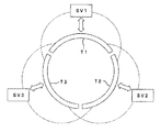
以下、図面を参照して本発明の実施の形態を説明する。図1〜図3は本発明の実施の一形態に係り、図1は通信システムの概念図、図2は通信システムの構成例を示す説明図、図3はゲートウェイを介した通信データの流れを示す説明図である。 Embodiments of the present invention will be described below with reference to the drawings. 1 to 3 relate to an embodiment of the present invention, FIG. 1 is a conceptual diagram of a communication system, FIG. 2 is an explanatory diagram showing a configuration example of a communication system, and FIG. 3 is a flow of communication data via a gateway. It is explanatory drawing shown.
図1に示す通信システム1は、図示しない自動車等の車両に搭載された複数の電子装置を接続するシステムであり、複数の通信系統Ti(i=1,2,…)が中央のコントロールユニット(中央制御部)CUにより統括して管理されている。通信系統Tiは、例えば、車両制御に適応したCAN(Controller Area Network;コントローラ・エリア・ネットワーク)通信系、画像やオーディオ等の情報通信系といったプロトコルの異なる各種の通信系を含むものである。
A
コントロールユニットCUは、異なる通信系統に対するゲートウェイ機能を有してシステム全体を管理するスーパーバイザであり、このスーパーバイザとしての機能が複数の通信系統Tiに対応して複数のスーパーバイザ(複数の管理部)SViに分割され、車内の通信網を多極管理している。このスーパーバイザの分割は、パワートレイン制御やシャーシ制御といった制御機能毎の分割に規定されることなく、車両全体としての総合的な機能や性能に応じて分類したデータを、複数系統で通信可能なように設定されている。 The control unit CU is a supervisor that has a gateway function for different communication systems and manages the entire system, and this supervisor function corresponds to a plurality of supervisors (a plurality of management units) SVi corresponding to a plurality of communication systems Ti. Divided to manage multi-pole communication networks in the car. This supervisor division is not defined for each control function, such as powertrain control or chassis control, so that data classified according to the overall function and performance of the entire vehicle can be communicated in multiple systems. Is set to
尚、図1における符号Ck(k=1,2,…)は、通信系統Tiに接続される複数の電子装置を示し、符号C’kは、他の通信系統Tjに接続される複数の電子装置を示している。 1 indicates a plurality of electronic devices connected to the communication system Ti, and C′k indicates a plurality of electrons connected to another communication system Tj. The device is shown.
各スーパーバイザSViは、自己の管理する通信系統Tiと送信及び受信の双方向通信で接続されると共に、他のスーパーバイザSVj(j=1,2,…;j≠i)が管理する通信系統Tj(j=1,2,…;j≠i)に、一方向の通信(送信のみ或いは受信のみ)が可能なようにゲートウェイを介して接続され、自身の通信系統における通信エラー処理(エラーの検出・通知・リカバリ)、各ノードに対する優先順位の決定、他の通信系統とのデータ通信処理等の管理を行う。
Each supervisor SVi is connected to a communication system Ti managed by itself by two-way transmission and reception communication, and a communication system Tj (j = 1, j ≠ i) managed by another supervisor SVj. j = 1, 2,...; j ≠ i) are connected via a gateway so that one-way communication (only transmission or reception) is possible, and communication error processing (error detection / Notification / recovery), priority determination for each node, management of data communication processing with other communication systems, and the like.
これにより、各ゲートウェイが一元的に連鎖されて全てのノード間の通信を網羅することができ、複数の通信系統の通信データの流れを一元化し、通信チャンネル数や通信負荷を低減してシステム全体の通信効率を向上することができる。 As a result, the gateways can be centrally linked to cover communication between all nodes, the communication data flow of multiple communication systems can be unified, the number of communication channels and communication load can be reduced, and the entire system Communication efficiency can be improved.
図2は、通信系統T1〜T4に対応して、コントロールユニットCUを4つのスーパーバイザSV1〜SV4に分割した例を示している。各スーパーバイザSV1〜SV4は、自身の通信系統に対しては送信及び受信の双方向の通信を行い、他方の通信系統に対しては、必要なデータの送信のみ(或いは受信のみ)の一方向の通信を行う。尚、図2中では、双方向の通信の流れを太線で示し、一方向の通信の流れを破線で示している。 FIG. 2 shows an example in which the control unit CU is divided into four supervisors SV1 to SV4 corresponding to the communication systems T1 to T4. Each supervisor SV1 to SV4 performs two-way communication of transmission and reception to its own communication system, and only one direction of necessary data transmission (or reception only) to the other communication system. Communicate. In FIG. 2, a bidirectional communication flow is indicated by a bold line, and a unidirectional communication flow is indicated by a broken line.
具体的には、スーパーバイザSV1は、自身の通信系統T1とスーパーバイザSV2の通信系統T2とに接続され、通信系統T1に接続される電子装置C1,C2間の通信データを管理すると共に、他の通信系統からの受信データ或いは或いは他の通信系統への送信データを管理する。スーパーバイザSV2は、自身の通信系統T2とスーパーバイザSV3の通信系統T3とに接続され、通信系統T2に接続される電子装置C3,C4,C5間の通信データを管理すると共に、他の通信系統からの受信データ或いは或いは他の通信系統への送信データを管理する。 Specifically, the supervisor SV1 is connected to its own communication system T1 and the communication system T2 of the supervisor SV2, manages communication data between the electronic devices C1 and C2 connected to the communication system T1, and performs other communication. Data received from the system or data transmitted to another communication system is managed. The supervisor SV2 is connected to the communication system T2 of the supervisor SV3 and the communication system T3 of the supervisor SV3, manages communication data between the electronic devices C3, C4, and C5 connected to the communication system T2, and from other communication systems. Manages received data or data transmitted to other communication systems.
また、スーパーバイザSV3は、自身の通信系統T3とスーパーバイザSV4の通信系統T4とに接続され、通信系統T3に接続される電子装置C6,C7,C8間の通信データを管理すると共に、他の通信系統からの受信データ或いは他の通信系統への送信データを管理する。スーパーバイザSV4は、自身の通信系統T4とスーパーバイザSV1の通信系統T1とに接続され、通信系統T4に接続される電子装置C9,C10間の通信データを管理すると共に、他の通信系統からの受信データ或いは他の通信系統への送信データを管理する。 The supervisor SV3 is connected to the communication system T3 of the supervisor SV4 and the communication system T4 of the supervisor SV4, manages communication data between the electronic devices C6, C7, and C8 connected to the communication system T3, and other communication systems. Data received from or transmitted data to other communication systems is managed. The supervisor SV4 is connected to its own communication system T4 and the communication system T1 of the supervisor SV1, manages communication data between the electronic devices C9 and C10 connected to the communication system T4, and receives data from other communication systems. Alternatively, data transmitted to other communication systems is managed.
このような接続形態において、各スーパーバイザSV1〜SV4が自身の通信系統以外の他の通信系統に、送信のみの一方向で接続されている接続形態と、各スーパーバイザSV1〜SV4が自身の通信系統以外の他の通信系統に、受信のみの一方向で接続されている接続形態とがある。 In such a connection form, each supervisor SV1 to SV4 is connected to another communication system other than its own communication system in one direction only for transmission, and each supervisor SV1 to SV4 is other than its own communication system. There is a connection form in which other communication systems are connected in one direction only for reception.
前者の接続形態では、例えば、通信系統T3の電子装置C6が通信系統T1の電子装置C1のデータを必要とする場合、電子装置C6がデータ送信要求を通信系統T3に送出すると、このデータ送信要求がスーパーバイザSV3によって通信系統T4に転送され、更に、スーパーバイザSV4によって通信系統T4から通信系統T1に転送される。 In the former connection mode, for example, when the electronic device C6 of the communication system T3 needs data of the electronic device C1 of the communication system T1, when the electronic device C6 sends a data transmission request to the communication system T3, the data transmission request Is transferred to the communication system T4 by the supervisor SV3, and further transferred from the communication system T4 to the communication system T1 by the supervisor SV4.
そして、通信系統T1に転送された電子装置C1に対するデータ送信要求に対して、電子装置C1が応答し、電子装置C6宛のデータを通信系統T1に送出すると、このデータがスーパーバイザSV1によって通信系統T2に転送され、スーパーバイザSV2によって通信系統T3に転送されることで、電子装置C6が電子装置C1のデータを受信することができる。 When the electronic device C1 responds to the data transmission request to the electronic device C1 transferred to the communication system T1 and sends the data addressed to the electronic device C6 to the communication system T1, this data is transmitted by the supervisor SV1 to the communication system T2. The electronic device C6 can receive the data of the electronic device C1 by being transferred to the communication system T3 by the supervisor SV2.
一方、後者の接続形態では、各スーパーバイザSV1〜SV4は、自身の通信系統以外に他の通信系統を監視しており、通信系統T3の電子装置C6が通信系統T1の電子装置C1のデータを必要とする場合、同様に、電子装置C6がデータ送信要求を通信系統T3に送出すると、このデータ送信要求が通信系統T3を監視する他の通信系統T2のスーパーバイザSV2によって受信され、通信系統T2に転送される。 On the other hand, in the latter connection form, each of the supervisors SV1 to SV4 monitors other communication systems in addition to its own communication system, and the electronic device C6 of the communication system T3 needs the data of the electronic device C1 of the communication system T1. Similarly, when the electronic device C6 sends a data transmission request to the communication system T3, the data transmission request is received by the supervisor SV2 of the other communication system T2 that monitors the communication system T3 and transferred to the communication system T2. Is done.
通信系統T2に転送されたデータ送信要求は、更に、通信系統T2を監視する他の通信系統T1のスーパーバイザSV1によって受信され、通信系統T1に転送される。そして、通信系統T1に転送された電子装置C1に対するデータ送信要求に対して、電子装置C1が応答し、電子装置C6宛のデータを通信系統T1に送出すると、このデータが通信系統T1を監視する他の通信系統T4のスーパーバイザSV4によって通信系統T4に転送され、更に、通信系統T4を監視する通信系統T3のスーパーバイザSV3によって通信系統T3に転送されることで、電子装置C6が電子装置C1のデータを受信することができる。 The data transmission request transferred to the communication system T2 is further received by the supervisor SV1 of another communication system T1 that monitors the communication system T2, and transferred to the communication system T1. Then, when the electronic device C1 responds to the data transmission request to the electronic device C1 transferred to the communication system T1, and sends the data addressed to the electronic device C6 to the communication system T1, this data monitors the communication system T1. The electronic device C6 is transferred to the communication system T4 by the supervisor SV4 of the other communication system T4, and further transferred to the communication system T3 by the supervisor SV3 of the communication system T3 that monitors the communication system T4. Can be received.
以上のように、各通信系統T1〜T4のスーパーバイザSV1〜SV4によって形成される一元的なゲートウェイの連鎖を介して、各電子装置C1〜C10の間の送受信が可能となる。すなわち、異なる通信系統に渡る通信を行う場合に、各電子装置C1〜C10のそれぞれが異なる通信系統に接続するための通信チャンネルを有する必要がなく、情報の流れを一方向化して通信データの機能毎の分割/整理が可能となる。これにより、通信チャンネル数の低減とバス負荷の低減とを図ることができ、システム全体の通信効率を向上すると共に、システムコストの低減に寄与することができる。 As described above, transmission / reception between the electronic devices C1 to C10 can be performed through a unified gateway chain formed by the supervisors SV1 to SV4 of the communication systems T1 to T4. That is, when performing communication over different communication systems, it is not necessary for each of the electronic devices C1 to C10 to have a communication channel for connecting to a different communication system, and the function of communication data is achieved by unidirectional information flow. Each division / organization is possible. Thereby, it is possible to reduce the number of communication channels and the bus load, thereby improving the communication efficiency of the entire system and contributing to the reduction of the system cost.
以上の図2に例示するシステム構成は、各スーパーバイザに、自身の通信系統以外の他の1系統の通信系統を接続する例であるが、各スーパーバイザに、自身の通信系統以外の他の通信系統を2系統以上接続するようにしても良い。 The system configuration illustrated in FIG. 2 is an example in which one supervisory communication system other than its own communication system is connected to each supervisor. However, other supervisory communication systems other than its own communication system are connected to each supervisor. Two or more systems may be connected.
図3は、スーパーバイザSV1〜SV3に、自身の通信系統以外の他の2系統の通信系統を接続した例を示している。すなわち、スーパーバイザSV1は、自身の管理下にある通信系統T1以外に、他の2つの通信系統T2,T3とゲートウェイを介して送信或いは受信のみの一方向で接続され、スーパーバイザSV2は、自身の管理下にある通信系統T2以外に、他の2つの通信系統T1,T3とゲートウェイを介して送信或いは受信のみの一方向で接続されている。同様に、スーパーバイザSV3は、自身の管理下にある通信系統T3以外に、他の2つの通信系統T1,T2とゲートウェイを介して送信或いは受信のみの一方向で接続されている。尚、図3においては、一方向の通信の流れを破線で示している。 FIG. 3 shows an example in which two communication systems other than the own communication system are connected to the supervisors SV1 to SV3. That is, the supervisor SV1 is connected to the other two communication systems T2 and T3 in one direction only through transmission or reception in addition to the communication system T1 under its management, and the supervisor SV2 is managed by itself. In addition to the communication system T2 below, the other two communication systems T1 and T3 are connected in one direction only for transmission or reception via a gateway. Similarly, the supervisor SV3 is connected to the other two communication systems T1 and T2 in one direction only for transmission or reception via the gateway in addition to the communication system T3 under its own management. In FIG. 3, the communication flow in one direction is indicated by a broken line.
このような接続形態においても、各スーパーバイザSV1〜SV4によるゲートウェイの連鎖を介して、各電子装置C1〜C10の間の送受信が行えるが、異なる通信系統を経由するデータ転送経路を短縮することができ、より効率的な通信が可能となる。 Even in such a connection form, transmission / reception between the electronic devices C1 to C10 can be performed through the gateway chain by the supervisors SV1 to SV4, but the data transfer path via different communication systems can be shortened. , More efficient communication becomes possible.
1 通信システム
C1〜C10 電子装置
CU コントロールユニット(中央制御部)
SV1〜SV4 スーパーバイザ(管理部)
T1〜T4 通信系統
1 Communication System C1-C10 Electronic Device CU Control Unit (Central Control Unit)
SV1-SV4 Supervisor (Management Department)
T1-T4 communication system
Claims (2)
上記中央制御部を、上記複数の通信系統のそれぞれを個別に管理する複数の管理部に分割し、
上記複数の管理部のそれぞれを、自身が管理する通信系統に送信及び受信の双方向通信可能に接続すると共に、他の管理部が管理する他の通信系統に、他の管理部を介することなく自身が有するゲートウェイ機能により送信或いは受信の一方向通信可能に接続し、
上記複数の管理部を上記ゲートウェイ機能を介して一元的に連鎖させることにより、上記複数の通信系統の全ての通信を網羅してデータの流れを一方向化することを特徴とする車両の通信システム。 In a vehicle communication system having a central control unit that manages and manages a plurality of communication systems mounted on a vehicle,
The central control unit is divided into a plurality of management units that individually manage each of the plurality of communication systems,
Each of the plurality of management units is connected to a communication system managed by itself so as to be capable of bidirectional transmission and reception, and to other communication systems managed by other management units without passing through another management unit. connect possible one-way communication of transmission or reception by the gateway functions of its own,
A vehicle communication system characterized in that all the communications of the plurality of communication systems are covered and the data flow is unidirectional by linking the plurality of management units in a unified manner via the gateway function. .
Priority Applications (1)
| Application Number | Priority Date | Filing Date | Title |
|---|---|---|---|
| JP2006035474A JP4841964B2 (en) | 2006-02-13 | 2006-02-13 | Vehicle communication system |
Applications Claiming Priority (1)
| Application Number | Priority Date | Filing Date | Title |
|---|---|---|---|
| JP2006035474A JP4841964B2 (en) | 2006-02-13 | 2006-02-13 | Vehicle communication system |
Publications (2)
| Publication Number | Publication Date |
|---|---|
| JP2007215125A JP2007215125A (en) | 2007-08-23 |
| JP4841964B2 true JP4841964B2 (en) | 2011-12-21 |
Family
ID=38493125
Family Applications (1)
| Application Number | Title | Priority Date | Filing Date |
|---|---|---|---|
| JP2006035474A Expired - Fee Related JP4841964B2 (en) | 2006-02-13 | 2006-02-13 | Vehicle communication system |
Country Status (1)
| Country | Link |
|---|---|
| JP (1) | JP4841964B2 (en) |
Family Cites Families (7)
| Publication number | Priority date | Publication date | Assignee | Title |
|---|---|---|---|---|
| US6331985B1 (en) * | 1997-08-21 | 2001-12-18 | Adc Telecommunications, Inc. | Telecommunication network with variable address learning, switching and routing |
| JP3844904B2 (en) * | 1999-03-31 | 2006-11-15 | 三菱電機株式会社 | Vehicle control communication system |
| US6771654B1 (en) * | 2000-01-24 | 2004-08-03 | Advanced Micro Devices, Inc. | Apparatus and method for sharing memory using a single ring data bus connection configuration |
| JP2001244864A (en) * | 2000-02-29 | 2001-09-07 | Hitachi Ltd | Wireless relay system |
| JP4124948B2 (en) * | 2000-08-25 | 2008-07-23 | 三菱電機株式会社 | Mobile electronic device |
| JP2003152762A (en) * | 2001-11-15 | 2003-05-23 | Denso Corp | Vehicle network system and distribution device used in the system |
| CN1739265A (en) * | 2003-10-17 | 2006-02-22 | 松下电器产业株式会社 | Data transmission system, data transmitter, and transmitting method |
-
2006
- 2006-02-13 JP JP2006035474A patent/JP4841964B2/en not_active Expired - Fee Related
Also Published As
| Publication number | Publication date |
|---|---|
| JP2007215125A (en) | 2007-08-23 |
Similar Documents
| Publication | Publication Date | Title |
|---|---|---|
| US20160182341A1 (en) | Switching over the Mode of a Control Unit Between a Diagnostic Bus and an External Ethernet Connection | |
| US9917725B2 (en) | Automotive neural network | |
| US20090323578A1 (en) | Wireless Vehicle Communication Method Utilizing Wired Backbone | |
| KR20190029994A (en) | Failure diagnosis apparatus and method for in-vehicle control unit | |
| KR101100336B1 (en) | Vehicle network system with intelligent integrated gateway and data processing method thereof | |
| JP2005027289A5 (en) | ||
| CN108282787B (en) | Method for collective detection of data in a mobile radio network | |
| CN115997374A (en) | Network with prioritized data streams loaded in vehicles | |
| CN113228601A (en) | Data exchange device and data exchange method for a vehicle, device and method for a vehicle component of a vehicle, and computer program | |
| Neumann et al. | Approaches for in-vehicle communication–an analysis and outlook | |
| JP4841964B2 (en) | Vehicle communication system | |
| CN117978576A (en) | Transmission system | |
| US7698039B2 (en) | Mobile communication system | |
| CN110574027B (en) | Vehicle control system verification method, verification device and control device | |
| CN109606290B (en) | Dual-topology networked control system for electric vehicle and its scheduling method | |
| KR101332339B1 (en) | Data transmitting method in can system | |
| JP4808127B2 (en) | In-vehicle communication method, in-vehicle communication system, relay device, and in-vehicle communication device | |
| JP4724095B2 (en) | Relay connection unit and in-vehicle communication system | |
| JP2007300331A (en) | In-vehicle database system | |
| CN115941749B (en) | Vehicle-mounted communication system, method and vehicle | |
| JP2005506801A (en) | Method for controlling a plurality of units networked together in one network and a network comprising networked units | |
| CN117156402A (en) | Intelligent network-connected automobile, internal and external network integration architecture, scheduling method and storage medium | |
| CN115051887A (en) | Data conversion method, interface conversion device and vehicle | |
| KR101063906B1 (en) | Communication interface module for MOTS network connection | |
| JP7360417B2 (en) | Management device, relay device, management method and management program |
Legal Events
| Date | Code | Title | Description |
|---|---|---|---|
| A621 | Written request for application examination |
Free format text: JAPANESE INTERMEDIATE CODE: A621 Effective date: 20081201 |
|
| A977 | Report on retrieval |
Free format text: JAPANESE INTERMEDIATE CODE: A971007 Effective date: 20110527 |
|
| A131 | Notification of reasons for refusal |
Free format text: JAPANESE INTERMEDIATE CODE: A131 Effective date: 20110531 |
|
| A521 | Request for written amendment filed |
Free format text: JAPANESE INTERMEDIATE CODE: A523 Effective date: 20110727 |
|
| TRDD | Decision of grant or rejection written | ||
| A01 | Written decision to grant a patent or to grant a registration (utility model) |
Free format text: JAPANESE INTERMEDIATE CODE: A01 Effective date: 20110927 |
|
| A01 | Written decision to grant a patent or to grant a registration (utility model) |
Free format text: JAPANESE INTERMEDIATE CODE: A01 |
|
| A61 | First payment of annual fees (during grant procedure) |
Free format text: JAPANESE INTERMEDIATE CODE: A61 Effective date: 20111005 |
|
| R150 | Certificate of patent or registration of utility model |
Ref document number: 4841964 Country of ref document: JP Free format text: JAPANESE INTERMEDIATE CODE: R150 Free format text: JAPANESE INTERMEDIATE CODE: R150 |
|
| FPAY | Renewal fee payment (event date is renewal date of database) |
Free format text: PAYMENT UNTIL: 20141014 Year of fee payment: 3 |
|
| R250 | Receipt of annual fees |
Free format text: JAPANESE INTERMEDIATE CODE: R250 |
|
| S531 | Written request for registration of change of domicile |
Free format text: JAPANESE INTERMEDIATE CODE: R313531 |
|
| R350 | Written notification of registration of transfer |
Free format text: JAPANESE INTERMEDIATE CODE: R350 |
|
| R250 | Receipt of annual fees |
Free format text: JAPANESE INTERMEDIATE CODE: R250 |
|
| R250 | Receipt of annual fees |
Free format text: JAPANESE INTERMEDIATE CODE: R250 |
|
| S533 | Written request for registration of change of name |
Free format text: JAPANESE INTERMEDIATE CODE: R313533 |
|
| R350 | Written notification of registration of transfer |
Free format text: JAPANESE INTERMEDIATE CODE: R350 |
|
| R250 | Receipt of annual fees |
Free format text: JAPANESE INTERMEDIATE CODE: R250 |
|
| R250 | Receipt of annual fees |
Free format text: JAPANESE INTERMEDIATE CODE: R250 |
|
| R250 | Receipt of annual fees |
Free format text: JAPANESE INTERMEDIATE CODE: R250 |
|
| R250 | Receipt of annual fees |
Free format text: JAPANESE INTERMEDIATE CODE: R250 |
|
| LAPS | Cancellation because of no payment of annual fees |