JP4834374B2 - Fixing roller manufacturing method and fixing roller - Google Patents
Fixing roller manufacturing method and fixing roller Download PDFInfo
- Publication number
- JP4834374B2 JP4834374B2 JP2005311118A JP2005311118A JP4834374B2 JP 4834374 B2 JP4834374 B2 JP 4834374B2 JP 2005311118 A JP2005311118 A JP 2005311118A JP 2005311118 A JP2005311118 A JP 2005311118A JP 4834374 B2 JP4834374 B2 JP 4834374B2
- Authority
- JP
- Japan
- Prior art keywords
- fixing roller
- layer
- metal foil
- roller
- manufacturing
- Prior art date
- Legal status (The legal status is an assumption and is not a legal conclusion. Google has not performed a legal analysis and makes no representation as to the accuracy of the status listed.)
- Expired - Fee Related
Links
Images


Landscapes
- Fixing For Electrophotography (AREA)
- Rolls And Other Rotary Bodies (AREA)
Description
本発明は定着ローラの製造方法及び定着ローラに関し、詳細には電磁誘導発熱を利用した定着ローラの耐久性向上の技術に関する。 The present invention relates to a fixing roller manufacturing method and a fixing roller , and more particularly to a technique for improving the durability of a fixing roller using electromagnetic induction heat generation.
電子写真方式の複写機、ファクシミリ、プリンタ等、トナーを用いた画像形成装置の定着装置としては、一般的に熱ローラ定着装置が用いられる。この熱ローラ定着装置は、内部に熱源を有する定着ローラと、定着ローラに押圧される機構を備えた加圧ローラを用いて構成されている。そして、この熱ローラ定着装置は、定着ローラと加圧ローラから構成される熱ローラ対の間に形成されるニップ部に未定着のトナー像を担持した被加熱体を通過させることにより、トナーを加熱溶融し、トナー像を被加熱体に固定する構成となっている。また、定着ローラの熱源としては、赤外線ヒーターを用いることが一般的であるが、投入した電力の一部が可視光線となってしまうことが避けられないことと、赤外線を受光する定着ローラの内壁での受光ロス等により、効率の限界がある。そこで、これらの問題点を解決するために従来よりいくつかの提案がなされている。 As a fixing device of an image forming apparatus using toner, such as an electrophotographic copying machine, a facsimile, a printer, or the like, a heat roller fixing device is generally used. This heat roller fixing device is configured by using a fixing roller having a heat source therein and a pressure roller having a mechanism pressed against the fixing roller. The heat roller fixing device passes a heated object carrying an unfixed toner image through a nip formed between a heat roller pair composed of a fixing roller and a pressure roller, thereby allowing the toner to pass through. The structure is such that the toner image is fixed to a heated body by being melted by heating. In general, an infrared heater is used as the heat source of the fixing roller. However, it is inevitable that a part of the input electric power becomes visible light, and the inner wall of the fixing roller that receives infrared light. There is a limit in efficiency due to loss of light received in the case. In order to solve these problems, several proposals have heretofore been made.
その一つとして特許文献1は、発熱ローラとして電磁誘導発熱を利用するものであり、定着ローラは回転駆動されるローラとこのローラを誘導発熱させるための誘導コイルを備えた電磁誘導発熱機構を持つ機構を有している。そして、誘導コイルは外部に設けられた交流電源に接続され、誘導コイルが交流電源により励磁されるとローラの外側に交流渦電流が誘起され、ローラの外側近傍が発熱する仕組みになっている。この場合、外側そのものが発熱源となるため、赤外線ヒーターを用いたときのような損失を無くすことができる。また、特許文献2は、発泡シリコーンゴムの熱伝導率を低くして弾性体層の断熱性を向上させ、その上に金属スリーブを接着させて低熱容量発熱体を形成している。更に、特許文献3は、多層の発熱層形成方法として、金属箔片をポリイミドに含有させたものを用いて形成している。
しかしながら、特許文献1によれば、電磁誘導発熱を利用した定着ローラの温度の立ち上がりを早めるには発熱層(金属層)を薄くすればよいが、定着ローラを他のローラに圧接させてシートの搬送を行う場合に、導電層と弾性層での硬さの差が大きく、ニップでの大きい応力時に接着界面に力がかかるため発熱層が破壊しやすいという欠点がある。また、特許文献2でも、硬い金属と弾性体界面で、応力集中のため起こりやすく、筒状の発熱体の場合一カ所の弱点が助長され破壊に至る。更に、特許文献3では、金属の界面が非常に多く、ここから酸化等により、金属とポリマー間での接着力が落ちてベルトの膜破壊に至りやすい。更に、一般的に整磁合金は、抵抗率が高いため電子による熱伝導率が小さく局所的な高温になりやすい。 However, according to Patent Document 1, the heating layer (metal layer) may be thinned in order to accelerate the rise of the temperature of the fixing roller using electromagnetic induction heat generation. However, the fixing roller is brought into pressure contact with another roller to form a sheet. When carrying, there is a drawback that the difference in hardness between the conductive layer and the elastic layer is large, and the heat generation layer is easily broken because a force is applied to the adhesive interface when a large stress is applied at the nip. Also in Patent Document 2, it tends to occur due to stress concentration at the interface between a hard metal and an elastic body, and in the case of a cylindrical heating element, one weak point is promoted and breaks down. Further, in Patent Document 3, there are very many metal interfaces, and from this, the adhesion between the metal and the polymer is reduced due to oxidation or the like, and the film of the belt is likely to be broken. Further, in general, a magnetic shunt alloy has a high resistivity, and thus has a low thermal conductivity due to electrons and is likely to have a high local temperature.
本発明はこれらの問題点を解決するためのものであり、製造効率を上げられ製造コストを抑えることができる定着ローラの製造方法及び定着ローラを提供することを目的とする。 SUMMARY An advantage of some aspects of the invention is to provide a fixing roller manufacturing method and a fixing roller capable of increasing manufacturing efficiency and suppressing manufacturing cost .
前記問題点を解決するために、本発明の定着ローラの製造方法は、定着ローラの中心軸となる芯金と、該芯金の表面に設けられた弾性体層と、該弾性体層の表面に設けられた多層発熱層とを備えた定着ローラを製造する方法である。そして、本発明の定着ローラの製造方法は、アルミニウム管を用いた芯金の表面に発泡シリコーンからなる弾性体層を形成する工程と、鉄とニッケルの整磁合金からなる金属箔状の発熱層と、該発熱層の一方の面にシロキサン結合を有する高分子材料からなる支持層とを形成した金属箔テープを、弾性体層の表面に支持層が接する向きで金属箔テープを複数回巻き付けて多層発熱層を形成する工程と、多層発熱層を加熱硬化する工程と、を有することに特徴がある。よって、製造効率を上げられ製造コストを抑えることができる。 In order to solve the above problems, a fixing roller manufacturing method according to the present invention includes a cored bar serving as a central axis of the fixing roller, an elastic layer provided on the surface of the cored bar, and a surface of the elastic layer. A fixing roller having a multilayer heat generating layer provided on the surface . Then, the fixing roller manufacturing method of the present invention includes a step of forming an elastic body layer made of foamed silicone on the surface of a metal core using an aluminum tube, and a metal foil-like heat generating layer made of a magnetic shunt alloy of iron and nickel. And a metal foil tape in which a support layer made of a polymer material having a siloxane bond is formed on one surface of the heat generation layer, and the metal foil tape is wound a plurality of times so that the support layer is in contact with the surface of the elastic layer. It is characterized by having a step of forming a multilayer heat generating layer and a step of heat curing the multilayer heat generating layer . Therefore, manufacturing efficiency can be increased and manufacturing cost can be reduced.
また、多層発熱層の最表面に、フッ素系高分子の離型層を設ける工程を有することにより、離型性が向上する。 Moreover , the mold release property is improved by having a step of providing a release layer of a fluorine-based polymer on the outermost surface of the multilayer heat generating layer.
更に、別の発明としての定着ローラは、上記の定着ローラの製造方法により製造されることを特徴がある。よって、安価な定着ローラを提供できる。 Furthermore , a fixing roller as another invention is characterized by being manufactured by the above-described fixing roller manufacturing method . Therefore, an inexpensive fixing roller can be provided.
本発明の定着ローラの製造方法は、アルミニウム管を用いた前記芯金の表面に発泡シリコーンからなる弾性体層を形成する工程と、鉄とニッケルの整磁合金からなる金属箔状の発熱層と、該発熱層の一方の面にシロキサン結合を有する高分子材料からなる支持層とを形成した金属箔テープを、弾性体層の表面に支持層が接する向きで金属箔テープを複数回巻き付けて多層発熱層を形成する工程と、多層発熱層を加熱硬化する工程と、を有している。よって、製造効率を上げられ製造コストを抑えることができる。
The fixing roller manufacturing method of the present invention comprises a step of forming an elastic body layer made of foamed silicone on the surface of the core metal using an aluminum tube, a metal foil-like heat generating layer made of a magnetic shunt alloy of iron and nickel, A metal foil tape formed with a support layer made of a polymer material having a siloxane bond on one surface of the heat generation layer is wound in multiple layers so that the support layer is in contact with the surface of the elastic layer. A step of forming a heat generation layer and a step of heat-curing the multilayer heat generation layer . Therefore, manufacturing efficiency can be increased and manufacturing cost can be reduced.
図1は本発明の一実施の形態例に係る定着装置の構成を示す概略断面図である。同図に示す本実施の形態例の定着装置1は、定着ローラ11と加圧ローラ12とIH磁界発生手段13を含んで構成されている。また、定着ローラ11は、芯金11−1と、当該芯金11−1の上に設けられた発泡シリコーンゴムの弾性体層11−2と、当該弾性体層11−2の上にIH(Induction Heating)発熱層である金属箔とシリコーン樹脂等の支持層の多層体を複数積層して構成された多層発熱層11−3との多層構造体で構成されており、更に最表面は通常離型性を有するフッ素系高分子よりなる例えばフッ素樹脂の離型層11−4で覆われている。このような多層構造の定着ローラ11の表面に対向するように外部に配置した加熱手段であるIH磁界発生手段13により定着ローラ11は加熱される。このIH磁界発生手段13はIH用コイルで構成されている。一定温度で加熱された定着ローラ11と加圧ローラ12とのニップ部に未定着のトナー像14を有する用紙15を通紙することで用紙に画像を定着させるものである。また、図1の定着ローラ11における多層発熱層11−3は、後述するように、例えば金、銀、銅、鉛、ニッケル、亜鉛、鉄、アルミニウム、マグネシウム、チタン、スズ又はその合金(整磁合金)等の導電性部材からなる金属箔と、当該層を多層にする際接着性を有するシリコーン樹脂等の支持層とを積層して構成するIH発熱層を多層構造体にして形成されている。
FIG. 1 is a schematic sectional view showing a configuration of a fixing device according to an embodiment of the present invention. The fixing device 1 according to the present embodiment shown in the figure includes a fixing roller 11, a
図2は本実施の形態例の定着装置における定着ローラの多層発熱層の構造の一例を示す断面図である。同図に示す多層発熱層11−3は、導電性部材からなる膜厚5〜20μmの金属箔21と、シリコーン系接着剤又はアクリル系の接着剤であって10〜20μmの膜厚の支持層22とを積層して構成するIH発熱層23を多層に形成した多層構造体を成している。
FIG. 2 is a cross-sectional view showing an example of the structure of the multilayer heat generating layer of the fixing roller in the fixing device of this embodiment. The multilayer heat generating layer 11-3 shown in the figure includes a
図3は本実施の形態例の定着装置における定着ローラの多層発熱層の構造の他の例を示す断面図である。同図に示す多層発熱層11−3は、膜厚5〜20μmの整磁合金の第1の金属箔24と、膜厚10μmのアルミニウムの第2の金属箔25とを含む金属箔26と、シリコーン系接着剤又はアクリル系の接着剤であって10〜20μmの膜厚の支持層22とを積層して構成するIH発熱層23を多層に形成した多層構造体を成している。
FIG. 3 is a cross-sectional view showing another example of the structure of the multilayer heat generating layer of the fixing roller in the fixing device of this embodiment. The multilayer heat generating layer 11-3 shown in the figure includes a
図4は本実施の形態例の定着装置における定着ローラの多層発熱層の作製工程の一例を示す図である。同図において、図1〜図3と同じ参照符号は同じ構成要素を示す。同図の(a)に示すように、図2に示す多層発熱層を形成するために、先ず膜厚5〜20μmの金属箔21にシリコーン系接着剤又はアクリル系の接着剤を10〜20μmの膜厚で塗布して形成する支持層22から構成する金属箔テープ27を作成する。また、同図の(b)に示すように、図3に示す多層発熱層を形成するために、膜厚5〜20μmの第1の金属箔24と、膜厚10μmの第2の金属箔25と、シリコーン系接着剤又はアクリル系の接着剤を10〜20μmの膜厚で第2の金属箔25に塗布して形成する支持層22から構成する金属箔テープ27を作成する。なお、この金属箔テープ27には、接着剤に対し離型性のあるセパレータを有するものを用い、製造効率を上げることができる。次に、同図の(c)に示すように、アルミニウム管等の芯金11−1の周りに断熱性の高い発泡シリコーンの弾性体層11−2を形成し、更に弾性体層11−2の上に同図の(a),(b)に示す金属箔テープ27を複数回巻き付ける。これにより、図1の多層構造体の多層発熱層11−3が形成される。この上に、必要であれば、さらにシリコーンゴムの弾性層を形成してもよい。更に、離型性向上から鑑みてローラの最外部には離型層としてのフッ素系高分子の材料を用いたフッ素樹脂層を形成することが好ましい。フッ素樹脂層の形成は、液体又は粉体塗料を塗布後に焼成する。または、フッ素樹脂チューブ(PFA樹脂等)を、接着層を介して接着してもよい。このようにして、本実施の形態例の定着装置における定着ローラを形成する。
FIG. 4 is a diagram showing an example of a process for producing a multilayer heat generating layer of the fixing roller in the fixing device of this embodiment. In the figure, the same reference numerals as those in FIGS. 1 to 3 denote the same components. As shown to (a) of the figure, in order to form the multilayer heat generating layer shown in FIG. 2, first, a silicone adhesive or an acrylic adhesive is applied to a
なお、本実施の形態例の定着装置において用いられるフッ素樹脂としては、焼成による溶融成膜性のよい、比較的融点の低いもの(250〜300℃)が好ましく選択される。具体的には、低分子量ポリテトラフルオロエチレン(PTFE)、テトラフロオロエチレン−ヘキサフルオロプロピレン共重合体(FEP)、テトラフルオロエチレン−パーフルオロアアルキアルビニルエーテル共重合体(PFA)の微粉末が挙げられる。低分子量ポリテトラフルオロエチレン(PTFE)粉末は、ルブロンL−5、L−2(ダイキン工業製)、MP1100、1200、1300、TLP−10F−1(三井デュポンフロロケミカル製)が知られている。テトラフルオロエチレン−ヘキサフルオロプロピレン共重合体(FEP)粉末は、532−8000(デュポン製)が知られている。テトラフルオロエチレン−パーフルオロアルキルビニルエーテル共重合体(PFA)は、MP−10、MP102、(三井デュポンフロロケミカル社製)が知られている。特にMFR(メルトフローレート製)が小さい流動性の低いものとして、MP103、MP300(三井デュポンフロロケミカル製)、AC−5600、AC5539(ダイキン工業製)等が適している。 As the fluororesin used in the fixing device of this embodiment, a resin having a good melt film-forming property by firing and a relatively low melting point (250 to 300 ° C.) is preferably selected. Specific examples include fine powders of low molecular weight polytetrafluoroethylene (PTFE), tetrafluoroethylene-hexafluoropropylene copolymer (FEP), and tetrafluoroethylene-perfluoroalkyl vinyl ether copolymer (PFA). It is done. As the low molecular weight polytetrafluoroethylene (PTFE) powder, Lubron L-5, L-2 (manufactured by Daikin Industries), MP1100, 1200, 1300, and TLP-10F-1 (manufactured by Mitsui DuPont Fluorochemical) are known. As the tetrafluoroethylene-hexafluoropropylene copolymer (FEP) powder, 532-8000 (manufactured by DuPont) is known. As the tetrafluoroethylene-perfluoroalkyl vinyl ether copolymer (PFA), MP-10, MP102 (manufactured by Mitsui DuPont Fluorochemical Co., Ltd.) are known. In particular, MP103, MP300 (manufactured by Mitsui DuPont Fluorochemical), AC-5600, AC5539 (manufactured by Daikin Industries) and the like are suitable as those having a low MFR (manufactured by melt flow rate) and low fluidity.
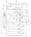
このような本実施の形態例の定着装置を搭載した画像形成装置を図5に示す。同図に示すように、デジタル複写機30は、主に、複写機本体31と、原稿自動送り装置(以下、ADFという)32と、自動仕分け装置33とを有する。また、複写機本体31は、原稿を読み取るスキャナ部34と、書込ユニット35、エンジン部36及び給紙ユニット37を有するプリンタ部38とを含んで構成されている。更に、ADF32は、読み取る原稿をスキャナ部34に送り、スキャナ部34で読み取った原稿を回収する。また、スキャナ部34は、光源と複数のミラーとを有するキャリッジ39、レンズ40及びCCD41を有し、ADF32で送られた原稿を走査して読み取る。書込ユニット35は、レーザ光源やポリゴンミラー等を有し、画像情報を含むレーザビーム42をエンジン部36に出射する。エンジン部36は、画像形成ユニット43、1次転写ユニット44、2次転写ユニット45、そして図1に示す本発明の定着装置46を有する。また、画像形成ユニット43は、感光体47の周囲に配置された帯電チャージャ48、シアン(C),マゼンタ(M),イエロー(Y),ブラック(K)からなるカラー現像部49及びドラムクリーニング部50を有し、帯電チャージャ48で帯電した感光体47上に書込みユニット35から出射されるレーザビーム42で静電潜像を形成し、形成した静電潜像をカラー現像部49で可視化してトナー像を形成する。更に、1次転写ユニット44は、中間転写ベルト51、1次転写部52、テンションローラ53、2次転写ローラ54、クリーニング部55及び基準位置センサ56を有し、感光体47に形成されたトナー像を中間転写ベルト51に1次転写して各色のトナー像を重ね合わす。中間転写ベルト51は感光体47上のトナー像を1次転写するとき以外は接離機構によって感光体47の表面から離れ、中間転写ベルト51に画像を1次転写するときだけ感光体47の表面に圧接される。2次転写ユニット45は中間転写ベルト51に転写されたトナー像を記録紙に2次転写する。定着装置46は記録紙に転写されたトナー像を熱と圧力で定着する。また、給紙ユニット37は複数の給紙カセット57a〜57cと手差トレイ58を有し、記録紙を2次転写ユニット45に送る。更に、自動仕分け装置33は複数段の仕分けビン59a〜59nを有し、画像が形成された記録紙を仕分けして排出する。
FIG. 5 shows an image forming apparatus equipped with such a fixing device of this embodiment. As shown in the figure, the digital copying
次に、本実施の形態例の定着装置における定着ローラの具体例を列記する。
(具体例1)
図4の(a)に示す金属箔テープとして、金、銀、銅、鉛、ニッケル、亜鉛、鉄、ステンレス、アルミニウム、マグネシウム、チタン、スズの厚さ10μmの金属箔に、シリコーン接着剤を約10μm塗布した箔テープ(以下塗布箔テープと呼ぶ)を作成する。アルミニウムの中空芯金に発泡シリコーンゴムを形成したものを準備し、金属箔テープを3層巻き付けて加熱硬化する。その後、その上に少なくとも柔らかく150℃程度で長時間耐久性のあるものとしてシリコーンゴムを加熱硬化させる。その外側にPFA樹脂を塗装し、加熱により最外層を形成する。各金属箔を用い、外径をφ40にしたものをそれぞれ作製した。これを、リコー製の複写機 MF4570をIH発熱用に改造した定着部を持つものに200℃設定で、白紙を200,000枚連続通紙したが、特に壊れたものはなかった。比較例として、付加型のシリコーンを用いた同様の構成では、10,000枚で発泡シリコーンとの界面で破壊した。
Next, specific examples of the fixing roller in the fixing device of this embodiment will be listed.
(Specific example 1)
As a metal foil tape shown in FIG. 4 (a), a silicone adhesive is approximately applied to a metal foil having a thickness of 10 μm of gold, silver, copper, lead, nickel, zinc, iron, stainless steel, aluminum, magnesium, titanium, and tin. A foil tape coated with 10 μm (hereinafter referred to as a coated foil tape) is prepared. An aluminum hollow core metal having foamed silicone rubber formed thereon is prepared, and three layers of metal foil tape are wound around and cured by heating. Thereafter, the silicone rubber is heat-cured as at least soft and durable at about 150 ° C. for a long time. A PFA resin is coated on the outside, and the outermost layer is formed by heating. Each metal foil was prepared with an outer diameter of φ40. Although 200,000 sheets of white paper were continuously passed through a Ricoh copier MF4570 having a fixing unit modified for IH heat generation at 200 ° C., nothing was broken. As a comparative example, in the same configuration using addition type silicone, 10,000 sheets were broken at the interface with foamed silicone.
(具体例2)
図4の(a)に示す金属箔テープとして、金、銀、銅、鉛、ニッケル、亜鉛、鉄、ステンレス、アルミニウム、マグネシウム、チタン、スズの厚さ20μmの金属箔に、シリコーン接着剤を約10μm塗布した塗布箔テープを作成する。アルミニウムの中空芯金に発泡シリコーンゴムを形成したものを準備し、金属箔テープを2層巻き付けて、加熱硬化する。その後、その上にシリコーンゴム加熱硬化させる。その外側にPFA樹脂を塗装し、加熱により最外層を形成する。金属箔により、外径をφ40にしたものをそれぞれ作成した。これを、(株)リコー製複写機 MF4570をIH発熱用に改造した定着部を持つものに200℃設定で、白紙を100,000枚連続通紙したが、特に壊れたものはなかった。
(Specific example 2)
As a metal foil tape shown in FIG. 4 (a), a silicone adhesive is approximately applied to a metal foil having a thickness of 20 μm of gold, silver, copper, lead, nickel, zinc, iron, stainless steel, aluminum, magnesium, titanium, and tin. A coated foil tape coated with 10 μm is prepared. A hollow core metal made of aluminum and foamed silicone rubber is prepared, and two layers of metal foil tape are wound around and cured by heating. Thereafter, the silicone rubber is heated and cured thereon. A PFA resin is coated on the outside, and the outermost layer is formed by heating. Each of the metal foils having an outer diameter of φ40 was prepared. 100,000 sheets of blank paper were continuously passed through a Ricoh Co., Ltd. copier MF4570 with a fixing unit modified for IH heat generation at 200 ° C., but nothing was broken.
(具体例3)
図4の(a)に示す金属箔テープとして、金、銀、銅、鉛、ニッケル、亜鉛、鉄、ステンレス、アルミニウム、マグネシウム、チタン、スズの厚さ5μmの金属箔に、シリコーン接着剤を約10μm塗布した塗布箔テープを作成する。アルミニウムの中空芯金に発泡シリコーンゴムを形成したものを準備し、金属箔テープを6層巻き付ける。加熱硬化する。その後、その上にシリコーンゴム加熱硬化させる。その外側にPFA樹脂を塗装し、加熱により最外層を形成する。金属箔により、外径をφ40にしたものをそれぞれ作成した。これを、(株)リコー製複写機 MF4570をIH発熱用に改造した定着部を持つものに200℃設定で、白紙を100,000枚連続通紙したが、特に壊れたものはなかった。
(Specific example 3)
As a metal foil tape shown in FIG. 4A, a silicone adhesive is applied to a metal foil having a thickness of 5 μm of gold, silver, copper, lead, nickel, zinc, iron, stainless steel, aluminum, magnesium, titanium, and tin. A coated foil tape coated with 10 μm is prepared. An aluminum hollow metal core formed with foamed silicone rubber is prepared, and a metal foil tape is wound around six layers. Heat cure. Thereafter, the silicone rubber is heated and cured thereon. A PFA resin is coated on the outside, and the outermost layer is formed by heating. Each of the metal foils having an outer diameter of φ40 was prepared. 100,000 sheets of blank paper were continuously passed through a Ricoh Co., Ltd. copier MF4570 with a fixing unit modified for IH heat generation at 200 ° C., but nothing was broken.
(具体例4)
図4の(a)に示す金属箔テープとして、金、銀、銅、鉛、ニッケル、亜鉛、鉄、ステンレス、アルミニウム、マグネシウム、チタン、スズの厚さ10μmの金属箔に、縮合型シリコーン接着剤を約10μm塗布した塗布箔テープを作成する。ここで、縮合型シリコーン接着剤の他に、シリコーン接着剤で触媒を使用する付加型シリコーン接着剤があるが、この付加型シリコーン接着剤は天然ゴム、合成ゴム、軟質塩ビ、アミン硬化エポキシ樹脂、ハンダフラックス等の硫黄、りん、窒素、錫などを含有する物質により触媒毒が発生し、硬化阻害を起こすためプロセス的に使いにくい。そして、アルミニウムの中空芯金発泡シリコーンゴムを形成したものを準備し、金属箔テープを3層巻き付ける。これを24時間常温放置する。その後、その上にシリコーンゴム加熱硬化させる。その外側にPFA樹脂を塗装し、加熱により最外層を形成する。金属箔により、外径をφ40にしたものをそれぞれ作成した。これを、リコー製複写機 MF4570をIH発熱用に改造した定着部を持つものに200℃設定で、白紙を100,000枚連続通紙したが、特に壊れたものはなかった。
(Specific example 4)
As a metal foil tape shown in FIG. 4A, a condensation type silicone adhesive is applied to a metal foil having a thickness of 10 μm of gold, silver, copper, lead, nickel, zinc, iron, stainless steel, aluminum, magnesium, titanium, and tin. A coated foil tape coated with about 10 μm is prepared. Here, in addition to the condensation type silicone adhesive, there is an addition type silicone adhesive that uses a catalyst with a silicone adhesive, and this addition type silicone adhesive includes natural rubber, synthetic rubber, soft vinyl chloride, amine-cured epoxy resin, Substances containing sulfur, phosphorus, nitrogen, tin, etc., such as solder flux, cause catalyst poisoning and inhibit curing, making it difficult to use in the process. And what formed the hollow core metal foaming silicone rubber of aluminum is prepared, and metal foil tape is wound three layers. This is left at room temperature for 24 hours. Thereafter, the silicone rubber is heated and cured thereon. A PFA resin is coated on the outside, and the outermost layer is formed by heating. Each of the metal foils having an outer diameter of φ40 was prepared. 100,000 sheets of white paper were continuously passed through a Ricoh copier MF4570 having a fixing part modified for IH heat generation at 200 ° C., but nothing was broken.
(具体例5)
図4の(b)に示す金属箔テープとして、Fe−Ni33%の15μmの第1の金属箔とアルミニウムの10μmの第2の金属箔とに、シリコーン接着剤を約10μm塗布した塗布箔テープを作成する。アルミニウムの中空芯金に発泡シリコーンゴムを形成したものを準備し、金属箔テープを2つ重ねにして2層巻き付ける。加熱硬化する。その後、その上にシリコーンゴム加熱硬化させる。その外側にPFA樹脂を塗装し、加熱により最外層を形成する。外径をφ40にしたものをそれぞれ作製した。これを、(株)リコー製複写機 MF4570をIH発熱用に改造した定着部を持つものに200℃設定で、白紙を200,000枚連続通紙したが、特に壊れたものはなかった。比較として、30μmの電鋳ニッケルスリーブを同じシリコーン接着剤により接着したものは、100,000枚程度で接着界面からずれて、破壊した。また、30μmの電鋳ニッケルスリーブをローラの両端で固定したものは、80,000枚程度で破壊した。
(Specific example 5)
As the metal foil tape shown in FIG. 4 (b), a coated foil tape in which a silicone adhesive is applied to about 10 μm on a 15 μm first metal foil of 33% Fe—Ni and a second metal foil of 10 μm aluminum. create. An aluminum hollow core metal having foamed silicone rubber formed thereon is prepared, and two metal foil tapes are stacked and wound in two layers. Heat cure. Thereafter, the silicone rubber is heated and cured thereon. A PFA resin is coated on the outside, and the outermost layer is formed by heating. Each having an outer diameter of φ40 was prepared. Although 200,000 sheets of white paper were continuously passed through a Ricoh Co., Ltd. copier MF4570 having a fixing unit modified for IH heat generation at 200 ° C., nothing was broken. As a comparison, a 30 μm electroformed nickel sleeve bonded with the same silicone adhesive was displaced from the bonding interface by about 100,000 sheets and destroyed. In addition, 30 μm electroformed nickel sleeves fixed at both ends of the roller were broken at about 80,000 sheets.
(具体例6)
図4の(b)に示す金属箔テープとして、Fe−Ni37−Cr10%の15μmの金属箔に、シリコーン接着剤を約10μm塗布した塗布箔テープを作成する。アルミニウムの中空芯金に発泡シリコーンゴムを形成したものを準備し、金属箔テープを3層巻き付ける。加熱硬化する。その後、その上にシリコーンゴム加熱硬化させる。その外側にPFA樹脂を塗装し、加熱により最外層を形成する。外径をφ40にしたものをそれぞれ作成した。これを、(株)リコー製複写機 MF4570をIH発熱用に改造した定着部を持つものに200℃設定で、白紙を100,000枚連続通紙したが、特に壊れたものはなかった。なお、同様に箔として、5、10,20,25,30μmのものを作製した。その結果、25μmのものは、50,000枚、30μmのものは、10,000枚にして、ローラの端から亀裂が入った。
(Specific example 6)
As a metal foil tape shown in FIG. 4B, a coated foil tape is prepared by applying about 10 μm of a silicone adhesive to a 15 μm metal foil of 10% Fe—Ni37—Cr. An aluminum hollow core metal having foamed silicone rubber formed thereon is prepared, and a metal foil tape is wound around three layers. Heat cure. Thereafter, the silicone rubber is heated and cured thereon. A PFA resin is coated on the outside, and the outermost layer is formed by heating. Each having an outer diameter of φ40 was prepared. 100,000 sheets of blank paper were continuously passed through a Ricoh Co., Ltd. copier MF4570 with a fixing unit modified for IH heat generation at 200 ° C., but nothing was broken. Similarly, foils of 5, 10, 20, 25, and 30 μm were prepared. As a result, 50,000 sheets for 25 μm and 10,000 sheets for 30 μm were cracked from the end of the roller.
(具体例7)
図4の(b)に示す金属箔テープとして、Fe−Ni40%の15μmの金属箔に、シリコーン接着剤を約10μm塗布した塗布箔テープを作成する。アルミニウムの中空芯金に発泡シリコーンゴムを形成したものを準備し、金属箔テープを3層巻き付ける。加熱硬化する。その後、その上にシリコーンゴム加熱硬化させる。その外側にPFA樹脂を塗装し、加熱により最外層を形成する。外径をφ40にしたものを作製した。これを、(株)リコー製複写機 MF4570をIH発熱用に改造した定着部を持つものに200℃設定で、白紙を100,000枚連続通紙したが、特に壊れたものはなかった。
(Specific example 7)
As a metal foil tape shown in FIG. 4B, a coated foil tape is prepared by applying about 10 μm of a silicone adhesive to a 15 μm metal foil of 40% Fe—Ni. An aluminum hollow core metal having foamed silicone rubber formed thereon is prepared, and a metal foil tape is wound around three layers. Heat cure. Thereafter, the silicone rubber is heated and cured thereon. A PFA resin is coated on the outside, and the outermost layer is formed by heating. A product with an outer diameter of φ40 was produced. 100,000 sheets of blank paper were continuously passed through a Ricoh Co., Ltd. copier MF4570 with a fixing unit modified for IH heat generation at 200 ° C., but nothing was broken.
(具体例8)
図4の(b)に示す金属箔テープとして、Fe−Ni40%の20μmの金属箔に、シリコーン接着剤を約10μm塗布した塗布箔テープを作成する。アルミニウムの中空芯金に発泡シリコーンゴムを形成したものを準備し、塗布箔を3層巻き付ける。加熱硬化する。その後、その上にシリコーンゴム加熱硬化させる。その外側にPFA樹脂を塗装し、加熱により最外層を形成する。外径をφ40にしたものを作製した。これを、(株)リコー製複写機 MF4570をIH発熱用に改造した定着部を持つものに200℃設定で、白紙を100,000枚連続通紙したが、特に壊れたものはなかった。
(Specific example 8)
As a metal foil tape shown in FIG. 4B, a coated foil tape is prepared by applying about 10 μm of a silicone adhesive to a 20 μm metal foil of 40% Fe—Ni. An aluminum hollow core metal having a foamed silicone rubber formed thereon is prepared, and three layers of coating foil are wound. Heat cure. Thereafter, the silicone rubber is heated and cured thereon. A PFA resin is coated on the outside, and the outermost layer is formed by heating. A product with an outer diameter of φ40 was produced. This paper was continuously fed 100,000 sheets of blank paper at 200 ° C. with a fixing unit modified from Ricoh Co., Ltd. MF4570 for IH heat generation, but nothing was broken.
以上の具体例1〜8の結果によれば、金属箔の厚さは5〜20μmとすることが好ましいことがわかる。 According to the results of the above specific examples 1 to 8, it is understood that the thickness of the metal foil is preferably 5 to 20 μm.
(具体例9)
具体例9として、具体例1又は具体例5の金属箔テープを用いて作成した定着ローラを(株)リコー製 MF4570に装着し、10,000枚、黒ベタ画像を通し、ローラ表面のトナーの付着状態を観察した。また、この定着ローラを(株)リコー製 MF4570に装着し、10,000枚、黒ベタ画像を通し、ローラ表面のトナー付着量と紙の巻き付きを見た。この結果である下記の表1からわかるように、表面粗さRzで5μm以下であれば、効果があることが確認された。なお、7μmのものは、8760枚で、ジャムが多発したため実験を取りやめている。
(Specific example 9)
As specific example 9, a fixing roller made using the metal foil tape of specific example 1 or specific example 5 is mounted on MF4570 manufactured by Ricoh Co., Ltd. The adhesion state was observed. Further, this fixing roller was mounted on MF4570 manufactured by Ricoh Co., Ltd., and 10,000 sheets of a solid black image were passed through, and the toner adhesion amount on the roller surface and the winding of the paper were observed. As can be seen from Table 1 below, this result was confirmed to be effective if the surface roughness Rz was 5 μm or less. The 7 μm one is 8760, and the experiment has been canceled because of frequent jams.

(具体例10)
具体例10は上述しました具体例1又は具体例5の金属箔テープを用いた作成した定着ローラを用い、(株)リコー製 IPSIO Color 8100で作成した未定着画像の通紙テストを行った例である。このIPSIO Color 8100のトナーは、離型性が不十分なため定着ローラにシリコンオイルを塗布するシリコンオイル含侵されたオイル塗布部材を追加している。このIPSIO Color 8100に10,000枚、黒ベタ画像を通し、ローラ表面のトナーの付着状態を観察した。特に大きな付着は観察されず。通常のものと何ら変わりがなかった。塗布部材を外したものは、60,000枚でローラへのトナーの顕著な付着がみられた。
(Specific Example 10)
Specific Example 10 is an example in which a sheet passing test of an unfixed image created with IPSIO Color 8100 manufactured by Ricoh Co., Ltd. was performed using the fixing roller prepared using the metal foil tape of Specific Example 1 or Specific Example 5 described above. It is. Since the toner of the IPSIO Color 8100 has insufficient releasability, an oil application member impregnated with silicone oil for applying silicone oil to the fixing roller is added. Through this IPSIO Color 8100, 10,000 sheets of black solid images were passed, and the adhesion state of the toner on the roller surface was observed. No significant adhesion was observed. There was no change from the normal one. With the application member removed, 60,000 sheets showed remarkable adhesion of toner to the roller.
(具体例11)
具体例11では具体例1又は具体例5の金属箔テープを用いて作成したローラで、表面粗さRzで、2μm以下としたものを作製した。(株)リコー製 MF4570の定着ユニットを用いたIH定着試験機を作製し、MF4570の未定着画像に加圧力を変えて、この定着ローラに対して通紙した。この結果、下記の表2に示すように、定着ローラに圧接する接触部分の用紙に対する加圧力が29.4(kPa)であるときは、トナー付着は見られずジャムも発生しなかったが、定着性(表2には記していない)が非常に悪くなった。また、392.2(kPa)の加圧力では、定着ローラへのトナー付着が見られ、かつジャムが多発した。定着性は、定着後のべた画像に面の布を擦りつけ顕著に布にトナーが付いているものを定着不良とした。よって、定着ローラに圧接する接触部分の1cm2あたりの用紙に対する加圧力は、49.0(kPa)以上で、392.2(kPa)未満が好ましい。
(Specific example 11)
In Example 11, a roller prepared using the metal foil tape of Example 1 or Example 5 and having a surface roughness Rz of 2 μm or less was prepared. An IH fixing tester using a fixing unit of MF4570 manufactured by Ricoh Co., Ltd. was prepared, and the pressure was changed to an unfixed image of MF4570, and paper was passed through the fixing roller. As a result, as shown in Table 2 below, when the pressure applied to the sheet at the contact portion in pressure contact with the fixing roller was 29.4 (kPa), no toner adhesion was observed and no jamming occurred. Fixability (not shown in Table 2) was very poor. Further, at a pressure of 392.2 (kPa), toner adhesion to the fixing roller was observed and jamming occurred frequently. The fixing property was determined to be poor fixing when the cloth on the surface was rubbed against the solid image after fixing and toner was noticeably attached to the cloth. Therefore, the pressure applied to the sheet per 1 cm 2 of the contact portion in pressure contact with the fixing roller is preferably 49.0 (kPa) or more and less than 392.2 (kPa).
なお、本発明は上記実施の形態例に限定されるものではなく、特許請求の範囲内の記載であれば多種の変形や置換可能であることは言うまでもない。 The present invention is not limited to the above-described embodiments, and it goes without saying that various modifications and substitutions are possible as long as they are described within the scope of the claims.
1;定着装置、11;定着ローラ、11−1;芯金、
11−2;弾性体層、11−3;多層発熱層、11−4;離型層、
12;加圧ローラ、13;IH磁界発生手段、14;トナー像、
15;用紙、21,26;金属箔、22;支持層、23;IH発熱層、
24;第1の金属箔、25;第2の金属箔、27;金属箔テープ、
30;画像形成装置。
1; fixing device, 11; fixing roller, 11-1;
11-2; elastic body layer, 11-3; multilayer heat generating layer, 11-4; release layer,
12; pressure roller; 13; IH magnetic field generating means; 14; toner image;
15; paper, 21, 26; metal foil, 22; support layer, 23; IH heating layer,
24; first metal foil; 25; second metal foil; 27; metal foil tape;
30: Image forming apparatus.
Claims (3)
アルミニウム管を用いた前記芯金の表面に発泡シリコーンからなる弾性体層を形成する工程と、
鉄とニッケルの整磁合金からなる金属箔状の発熱層と、該発熱層の一方の面にシロキサン結合を有する高分子材料からなる支持層とを形成した金属箔テープを、前記弾性体層の表面に前記支持層が接する向きで前記金属箔テープを複数回巻き付けて多層発熱層を形成する工程と、
前記多層発熱層を加熱硬化する工程と、
を有することを特徴とする定着ローラの製造方法。 In a method of manufacturing a fixing roller , comprising a cored bar serving as a central axis of the fixing roller, an elastic layer provided on the surface of the cored bar, and a multilayer heat generating layer provided on the surface of the elastic layer.
Forming an elastic body layer made of foamed silicone on the surface of the core metal using an aluminum tube;
A metal foil tape in which a metal foil-like heat generating layer made of a magnetic shunt alloy of iron and nickel and a support layer made of a polymer material having a siloxane bond on one surface of the heat generating layer is formed on the elastic layer. A step of wrapping the metal foil tape a plurality of times in a direction in which the support layer is in contact with the surface to form a multilayer heating layer;
Heat curing the multilayer heat generating layer;
A method for manufacturing a fixing roller , comprising:
Priority Applications (1)
| Application Number | Priority Date | Filing Date | Title |
|---|---|---|---|
| JP2005311118A JP4834374B2 (en) | 2005-04-06 | 2005-10-26 | Fixing roller manufacturing method and fixing roller |
Applications Claiming Priority (3)
| Application Number | Priority Date | Filing Date | Title |
|---|---|---|---|
| JP2005109335 | 2005-04-06 | ||
| JP2005109335 | 2005-04-06 | ||
| JP2005311118A JP4834374B2 (en) | 2005-04-06 | 2005-10-26 | Fixing roller manufacturing method and fixing roller |
Publications (3)
| Publication Number | Publication Date |
|---|---|
| JP2006313304A JP2006313304A (en) | 2006-11-16 |
| JP2006313304A5 JP2006313304A5 (en) | 2008-10-09 |
| JP4834374B2 true JP4834374B2 (en) | 2011-12-14 |
Family
ID=37534815
Family Applications (1)
| Application Number | Title | Priority Date | Filing Date |
|---|---|---|---|
| JP2005311118A Expired - Fee Related JP4834374B2 (en) | 2005-04-06 | 2005-10-26 | Fixing roller manufacturing method and fixing roller |
Country Status (1)
| Country | Link |
|---|---|
| JP (1) | JP4834374B2 (en) |
Families Citing this family (5)
| Publication number | Priority date | Publication date | Assignee | Title |
|---|---|---|---|---|
| JP5177348B2 (en) * | 2007-03-12 | 2013-04-03 | 株式会社リコー | Fixing device and image forming apparatus using the same |
| JP4835654B2 (en) * | 2008-06-18 | 2011-12-14 | コニカミノルタビジネステクノロジーズ株式会社 | Fixing apparatus and image forming apparatus |
| JP2010002507A (en) * | 2008-06-18 | 2010-01-07 | Konica Minolta Business Technologies Inc | Fixing belt used for fixing device, fixing device, and image forming device |
| JP2010002508A (en) * | 2008-06-18 | 2010-01-07 | Konica Minolta Business Technologies Inc | Fixing belt used for fixing apparatus, the fixing apparatus and image forming apparatus |
| JP5359362B2 (en) * | 2009-02-24 | 2013-12-04 | 富士ゼロックス株式会社 | Fixing device and image forming apparatus |
Family Cites Families (4)
| Publication number | Priority date | Publication date | Assignee | Title |
|---|---|---|---|---|
| JPH10198202A (en) * | 1996-12-27 | 1998-07-31 | Canon Inc | Heating belt, heater and image forming device |
| JP2003084593A (en) * | 2001-06-28 | 2003-03-19 | Toho Kasei Kk | Endless belt and manufacturing method therefor |
| JP4025653B2 (en) * | 2003-01-24 | 2007-12-26 | 松下電器産業株式会社 | Fixing belt, magnetic roller, and image forming apparatus |
| JP2004325678A (en) * | 2003-04-23 | 2004-11-18 | Konica Minolta Business Technologies Inc | Image forming apparatus |
-
2005
- 2005-10-26 JP JP2005311118A patent/JP4834374B2/en not_active Expired - Fee Related
Also Published As
| Publication number | Publication date |
|---|---|
| JP2006313304A (en) | 2006-11-16 |
Similar Documents
| Publication | Publication Date | Title |
|---|---|---|
| US8195076B2 (en) | Fixing device and image forming apparatus including same | |
| US7796933B2 (en) | Fixing device using electromagnetic induction heating and image forming apparatus including same | |
| US6031215A (en) | Image heating device using induction heating for image heating | |
| US8055173B2 (en) | Fixing apparatus and image forming apparatus | |
| JP2007226125A (en) | Fixing apparatus, image forming apparatus provided with the same and image forming method | |
| US20110217096A1 (en) | Fixing device | |
| JP2007226124A (en) | Fixing device | |
| US20080199229A1 (en) | Transfer-fixing device, image forming apparatus, and transfer-fixing method | |
| JP4834374B2 (en) | Fixing roller manufacturing method and fixing roller | |
| US20110135355A1 (en) | Heating device and image forming apparatus | |
| JP2010181492A (en) | Endless belt, fixing device and image forming apparatus | |
| JP5359362B2 (en) | Fixing device and image forming apparatus | |
| JP5029656B2 (en) | Electromagnetic induction heating device, fixing device using the same, and image forming apparatus | |
| JP6123198B2 (en) | Fixing apparatus and image forming apparatus | |
| JP5061849B2 (en) | Fixing apparatus and image forming apparatus | |
| JP2012203185A (en) | Fixing device and image forming apparatus | |
| EP1879081A1 (en) | Image forming apparatus including fixer having fixing roller | |
| JP4623106B2 (en) | Fixing apparatus and image forming apparatus | |
| JP2005156826A (en) | Fixing apparatus and image forming apparatus | |
| JP2008224835A (en) | Image fixing components, fixing unit, and image forming device | |
| JP2009217159A (en) | Fixing device and image forming apparatus | |
| JP4929879B2 (en) | Fixing belt, fixing device, and image forming apparatus | |
| JP2008040152A (en) | Roller, fixing apparatus and image forming apparatus | |
| JP5045702B2 (en) | Electromagnetic induction heating body, electromagnetic induction heating apparatus using the same, fixing apparatus, and image forming apparatus | |
| JP5071912B2 (en) | Fixing roller, fixing device and image forming apparatus |
Legal Events
| Date | Code | Title | Description |
|---|---|---|---|
| A521 | Written amendment |
Free format text: JAPANESE INTERMEDIATE CODE: A523 Effective date: 20080822 |
|
| A621 | Written request for application examination |
Free format text: JAPANESE INTERMEDIATE CODE: A621 Effective date: 20080822 |
|
| RD02 | Notification of acceptance of power of attorney |
Free format text: JAPANESE INTERMEDIATE CODE: A7422 Effective date: 20091207 |
|
| RD04 | Notification of resignation of power of attorney |
Free format text: JAPANESE INTERMEDIATE CODE: A7424 Effective date: 20100115 |
|
| A977 | Report on retrieval |
Free format text: JAPANESE INTERMEDIATE CODE: A971007 Effective date: 20110126 |
|
| A131 | Notification of reasons for refusal |
Free format text: JAPANESE INTERMEDIATE CODE: A131 Effective date: 20110128 |
|
| TRDD | Decision of grant or rejection written | ||
| A01 | Written decision to grant a patent or to grant a registration (utility model) |
Free format text: JAPANESE INTERMEDIATE CODE: A01 Effective date: 20110909 |
|
| A01 | Written decision to grant a patent or to grant a registration (utility model) |
Free format text: JAPANESE INTERMEDIATE CODE: A01 |
|
| A61 | First payment of annual fees (during grant procedure) |
Free format text: JAPANESE INTERMEDIATE CODE: A61 Effective date: 20110926 |
|
| R150 | Certificate of patent or registration of utility model |
Free format text: JAPANESE INTERMEDIATE CODE: R150 |
|
| FPAY | Renewal fee payment (event date is renewal date of database) |
Free format text: PAYMENT UNTIL: 20140930 Year of fee payment: 3 |
|
| LAPS | Cancellation because of no payment of annual fees |