JP4833010B2 - Solid-state imaging device - Google Patents
Solid-state imaging device Download PDFInfo
- Publication number
- JP4833010B2 JP4833010B2 JP2006259231A JP2006259231A JP4833010B2 JP 4833010 B2 JP4833010 B2 JP 4833010B2 JP 2006259231 A JP2006259231 A JP 2006259231A JP 2006259231 A JP2006259231 A JP 2006259231A JP 4833010 B2 JP4833010 B2 JP 4833010B2
- Authority
- JP
- Japan
- Prior art keywords
- output
- incident light
- signal
- amplifier
- total amount
- Prior art date
- Legal status (The legal status is an assumption and is not a legal conclusion. Google has not performed a legal analysis and makes no representation as to the accuracy of the status listed.)
- Expired - Fee Related
Links
- 238000003384 imaging method Methods 0.000 title claims description 72
- 238000009825 accumulation Methods 0.000 claims description 48
- 238000012544 monitoring process Methods 0.000 claims description 47
- 230000003071 parasitic effect Effects 0.000 claims description 15
- 238000005513 bias potential Methods 0.000 claims description 13
- 239000003990 capacitor Substances 0.000 claims description 10
- 230000003321 amplification Effects 0.000 claims description 7
- 238000003199 nucleic acid amplification method Methods 0.000 claims description 7
- 238000012546 transfer Methods 0.000 claims description 6
- 238000006243 chemical reaction Methods 0.000 description 24
- 238000010586 diagram Methods 0.000 description 5
- 230000010354 integration Effects 0.000 description 5
- 238000012986 modification Methods 0.000 description 4
- 230000004048 modification Effects 0.000 description 4
- 210000000214 mouth Anatomy 0.000 description 4
- 238000007599 discharging Methods 0.000 description 2
- 230000007423 decrease Effects 0.000 description 1
- 230000000694 effects Effects 0.000 description 1
- 230000020169 heat generation Effects 0.000 description 1
- 238000000034 method Methods 0.000 description 1
- 238000012545 processing Methods 0.000 description 1
- 230000002123 temporal effect Effects 0.000 description 1
Images


Landscapes
- Solid State Image Pick-Up Elements (AREA)
- Transforming Light Signals Into Electric Signals (AREA)
Description
本発明は、入射光量に応じた量の電荷を発生するフォトダイオードを各々有する複数の画素部が配列された受光部を備える固体撮像装置に関するものである。 The present invention relates to a solid-state imaging device including a light receiving unit in which a plurality of pixel units each having a photodiode that generates an amount of electric charge corresponding to an amount of incident light is arranged.
固体撮像装置は、フォトダイオードを各々有する複数の画素部が2次元配置された受光部を備えており、また、各画素部のフォトダイオードで発生した電荷の量に応じたデジタル値を出力するAD変換回路をも備える場合がある。このような固体撮像装置において、画素数が増加の一途にあり、また、撮像の高速化が求められている。このような画素数の増加と撮像の高速化は、一般に固体撮像装置の消費電力の増加をもたらすことになる。
ところで、固体撮像装置の用途によっては、消費電力の増加を抑制したい場合や、寧ろ消費電力を低減したい場合がある。例えば、固体撮像装置を長時間に亘ってバッテリ駆動したい場合や、固体撮像装置を含む機器の構造上の理由から発熱を抑制したい場合、等である。本発明は、上記問題点を解消する為になされたものであり、画素数の増加や撮像の高速化を図る場合であっても消費電力の増大を抑制することができる固体撮像装置を提供することを目的とする。 By the way, depending on the application of the solid-state imaging device, there is a case where it is desired to suppress an increase in power consumption, or rather, it is desired to reduce power consumption. For example, when it is desired to drive the solid-state imaging device with a battery for a long time, or when it is desired to suppress heat generation due to the structure of the device including the solid-state imaging device. The present invention has been made to solve the above-described problems, and provides a solid-state imaging device capable of suppressing an increase in power consumption even when increasing the number of pixels and increasing the imaging speed. For the purpose.
本発明に係る固体撮像装置は、(1) 入射光量に応じた量の電荷を発生するフォトダイオードと、ゲート端子に形成された寄生容量部に蓄積されている電荷の量に応じた電圧値を出力する増幅用トランジスタと、フォトダイオードで発生した電荷を増幅用トランジスタのゲート端子へ転送する転送用トランジスタと、寄生容量部の電荷を初期化する放電用トランジスタと、増幅用トランジスタから出力される電圧値を選択的に出力する選択用トランジスタとを各々有する複数の画素部を含み、電荷蓄積動作制御信号が指示する期間に複数の画素部それぞれにおいてフォトダイオードで発生した電荷を寄生容量部に蓄積する受光部と、(2) 複数の画素部それぞれにおける電荷蓄積動作の後に、複数の画素部それぞれの選択用トランジスタから出力される電圧値に応じたデジタル値を出力する出力部と、(3) 第1入力端子,第2入力端子および出力端子を有するアンプを含み、複数の画素部それぞれの放電用トランジスタにアンプの第1入力端子が接続され、複数の画素部それぞれの寄生容量部の電荷を初期化する為のバイアス電位にアンプの第2入力端子が接続され、アンプの出力端子からの出力信号に基づいて、複数の画素部それぞれのフォトダイオードに入射する光の総量を表す入射光総量信号を出力する入射光総量監視部と、を備えることを特徴とする。また、本発明に係る固体撮像装置は、入射光総量監視部から出力される入射光総量信号を入力し、この入射光総量信号が表す入射光総量が閾値より大きいときに受光部の複数の画素部それぞれに対して電荷蓄積動作を指示する電荷蓄積動作制御信号を生成する制御部を更に備えるのが好適である。 The solid-state imaging device according to the present invention includes (1) a photodiode that generates an amount of charge according to the amount of incident light, and a voltage value according to the amount of charge accumulated in the parasitic capacitance formed at the gate terminal. Amplifying transistor to be output, a transfer transistor for transferring the charge generated in the photodiode to the gate terminal of the amplifying transistor, a discharging transistor for initializing the charge in the parasitic capacitance portion, and a voltage output from the amplifying transistor A plurality of pixel portions each having a selection transistor for selectively outputting a value, and charges generated in the photodiodes in each of the plurality of pixel portions are accumulated in the parasitic capacitance portion in a period indicated by the charge accumulation operation control signal (2) After the charge accumulation operation in each of the plurality of pixel units, the light is output from the selection transistor in each of the plurality of pixel units. An output unit that outputs a digital value corresponding to the voltage value to be output; and (3) an amplifier having a first input terminal, a second input terminal, and an output terminal. The input terminal is connected, the second input terminal of the amplifier is connected to a bias potential for initializing the charges of the parasitic capacitance portions of each of the plurality of pixel portions, and a plurality of signals are output based on an output signal from the output terminal of the amplifier. And an incident light total amount monitoring unit that outputs an incident light total amount signal indicating the total amount of light incident on the photodiodes of each pixel portion. The solid-state imaging device according to the present invention receives a total incident light amount signal output from the incident light total amount monitoring unit, and a plurality of pixels of the light receiving unit when the total incident light amount represented by the incident light total amount signal is larger than a threshold value. It is preferable to further include a control unit that generates a charge storage operation control signal for instructing the charge storage operation to each unit.
本発明に係る固体撮像装置では、受光部に含まれる各画素部は、APS(Active Pixel Sensor)方式のものであって、フォトダイオード、増幅用トランジスタ、転送用トランジスタ、放電用トランジスタおよび選択用トランジスタを有している。また、入射光総量監視部に含まれるアンプの第1入力端子は、複数の画素部それぞれの放電用トランジスタに接続される。アンプの第2入力端子は、複数の画素部それぞれの増幅用トランジスタのゲート端子に形成された寄生容量部の電荷を初期化する為のバイアス電位に接続される。アンプの第1入力端子は、第2入力端子に対してイマジナリショートの関係にあるので、同じくバイアス電位となっている。したがって、各画素部において、放電用トランジスタおよび転送用トランジスタがオン状態となっているときには、増幅用トランジスタのゲート端子の電位はリセットされるともに、フォトダイオードで発生した電荷は入射光総量監視部のアンプの第1入力端子に入力される。 In the solid-state imaging device according to the present invention, each pixel unit included in the light receiving unit is of an APS (Active Pixel Sensor) type, and includes a photodiode, an amplification transistor, a transfer transistor, a discharge transistor, and a selection transistor. have. In addition, the first input terminal of the amplifier included in the total incident light amount monitoring unit is connected to the discharging transistor of each of the plurality of pixel units. The second input terminal of the amplifier is connected to a bias potential for initializing the charge of the parasitic capacitance portion formed at the gate terminal of the amplification transistor of each of the plurality of pixel portions. Since the first input terminal of the amplifier is in an imaginary short relationship with the second input terminal, it has the same bias potential. Accordingly, in each pixel portion, when the discharge transistor and the transfer transistor are in the ON state, the potential of the gate terminal of the amplification transistor is reset and the charge generated in the photodiode is stored in the incident light total amount monitoring portion. Input to the first input terminal of the amplifier.
入射光総量監視部のアンプの出力端子からの出力信号に基づいて、複数の画素部それぞれのフォトダイオードに入射する光の総量を表す入射光総量信号が得られる。そして、この入射光総量信号が表す入射光総量が閾値より大きいときに、受光部の各画素部に対して電荷蓄積動作を指示する電荷蓄積動作制御信号が生成される。受光部では、電荷蓄積動作制御信号が指示する期間に各画素部においてフォトダイオードで発生した電荷が増幅用トランジスタのゲート端子の寄生容量部に蓄積され、その後に、各画素部の選択用トランジスタから出力される電圧値に応じたデジタル値が出力部から出力される。 Based on the output signal from the output terminal of the amplifier of the total incident light amount monitoring unit, an incident light total amount signal representing the total amount of light incident on the photodiodes of each of the plurality of pixel units is obtained. Then, when the total incident light amount represented by the total incident light amount signal is larger than the threshold value, a charge accumulation operation control signal for instructing the charge accumulation operation to each pixel unit of the light receiving unit is generated. In the light receiving portion, the charge generated in the photodiode in each pixel portion during the period indicated by the charge accumulation operation control signal is accumulated in the parasitic capacitance portion of the gate terminal of the amplifying transistor, and then from the selection transistor in each pixel portion. A digital value corresponding to the output voltage value is output from the output unit.
本発明に係る固体撮像装置では、入射光総量監視部は、アンプの第1入力端子と出力端子との間に設けられた容量素子およびスイッチと、アンプの出力端子から出力される電圧値と基準電圧値とを大小比較して当該比較結果を表す信号を入射光総量信号として出力する比較回路とを更に含み、スイッチが入射光総量信号のレベルに応じて開閉制御されるのが好適である。この場合には、比較回路から出力される入射光総量信号は、受光部への入射光量に応じたパルス繰返し周波数を有するパルス信号となる。 In the solid-state imaging device according to the present invention, the incident light total amount monitoring unit includes a capacitance element and a switch provided between the first input terminal and the output terminal of the amplifier, a voltage value output from the output terminal of the amplifier, and a reference It is preferable that the circuit further includes a comparison circuit that compares the voltage values with each other and outputs a signal representing the comparison result as an incident light total amount signal, and the switch is controlled to be opened and closed according to the level of the incident light total amount signal. In this case, the incident light total amount signal output from the comparison circuit is a pulse signal having a pulse repetition frequency corresponding to the amount of light incident on the light receiving unit.
本発明に係る固体撮像装置では、入射光総量監視部は、アンプの第1入力端子と出力端子との間に設けられた容量素子およびスイッチを更に含み、スイッチが一定周期で開閉制御され、アンプの出力端子からの出力信号を入射光総量信号として出力するのが好適である。この場合には、アンプから出力される入射光総量信号は、受光部への入射光量に応じたピーク値を有する三角波信号となる。 In the solid-state imaging device according to the present invention, the total incident light amount monitoring unit further includes a capacitive element and a switch provided between the first input terminal and the output terminal of the amplifier, and the switch is controlled to be opened and closed at a constant period. It is preferable to output an output signal from the output terminal as an incident light total amount signal. In this case, the incident light total amount signal output from the amplifier is a triangular wave signal having a peak value corresponding to the amount of incident light to the light receiving unit.
本発明に係る固体撮像装置は、入射光総量監視部は、アンプの第1入力端子と出力端子との間に設けられた抵抗器を更に含み、アンプの出力端子からの出力信号を入射光総量信号として出力するのが好適である。この場合には、アンプから出力される入射光総量信号は、受光部への入射光量に応じた電圧値となる。 In the solid-state imaging device according to the present invention, the total incident light amount monitoring unit further includes a resistor provided between the first input terminal and the output terminal of the amplifier, and the output signal from the output terminal of the amplifier is input to the total amount of incident light. It is preferable to output as a signal. In this case, the incident light total amount signal output from the amplifier has a voltage value corresponding to the amount of incident light to the light receiving unit.
本発明に係る固体撮像装置は、画素数の増加や撮像の高速化を図る場合であっても、消費電力の増大を抑制することができる。 The solid-state imaging device according to the present invention can suppress an increase in power consumption even when increasing the number of pixels or increasing the imaging speed.
以下、添付図面を参照して、本発明を実施するための最良の形態を詳細に説明する。なお、図面の説明において同一の要素には同一の符号を付し、重複する説明を省略する。 The best mode for carrying out the present invention will be described below in detail with reference to the accompanying drawings. In the description of the drawings, the same elements are denoted by the same reference numerals, and redundant description is omitted.
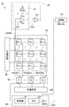
図1は、本実施形態に係る固体撮像装置1の構成図である。この図に示される固体撮像装置1は、受光部10、入射光総量監視部20、行選択部30、列選択部40、電圧保持部50、出力部60および制御部70を備える。なお、この図では、要素間の配線については省略または簡略化されている。
FIG. 1 is a configuration diagram of a solid-
受光部10は、入射した光の像を撮像するためのものであり、M行N列に2次元配列された画素部P1,1〜PM,Nを含む。画素部Pm,nは第m行第n列に位置している。M×N個の画素部P1,1〜PM,Nは、共通の構成を有していて、入射光量に応じた量の電荷を発生するフォトダイオードと、該電荷を蓄積する電荷蓄積部とを有している。受光部10は、制御部70から出力される電荷蓄積動作制御信号が指示する期間に、M×N個の画素部P1,1〜PM,Nそれぞれにおいてフォトダイオードで発生した電荷を電荷蓄積部により蓄積する。また、それ以外の期間には、受光部10は、M×N個の画素部P1,1〜PM,Nそれぞれにおいてフォトダイオードで発生した電荷を入射光総量監視部20へ出力する。なお、M,Nは2以上の整数であり、mは1以上M以下の整数であり、nは1以上N以下の整数である。
The
入射光総量監視部20は、画素部P1,1〜PM,Nのフォトダイオードに入射する光の総量を表す入射光総量信号を出力するものである。入射光総量監視部20は、反転入力端子,非反転入力端子および出力端子を有するアンプA20を含む。アンプA20の反転入力端子は、画素部P1,1〜PM,Nそれぞれに接続されている。アンプA20の非反転入力端子は、バイアス電位Vb1に接続されている。入射光総量監視部20は、アンプA20の出力端子からの出力信号に基づいて、入射光総量信号を出力する。この入射光総量監視部20の詳細については、後に図2を用いて説明する。
The incident light total
行選択部30は、制御部70による制御の下に、受光部10における各行を順次に指定して、その指定した第m行のN個の画素部Pm,1〜Pm,Nそれぞれの電荷蓄積部に蓄積された電荷の量に応じた電圧値を電圧保持部50へ出力させる。行選択部30は、M段のシフトレジスタ回路を含み、このシフトレジスタ回路の各段の出力ビットにより、受光部10における各行を順次に指定することができる。
The
電圧保持部50は、共通の構成を有するN個の保持回路H1〜HNを含む。保持回路Hnは、受光部10における第n列のM個の画素部P1,n〜PM,nと接続されていて、これらのうちの何れかの画素部Pm,nから出力された電圧値を入力し、その入力した電圧値を保持して出力する。保持回路Hnは、雑音成分が重畳された信号成分を表す電圧値を保持するとともに、雑音成分を表す電圧値も保持することができる。
The
列選択部40は、電圧保持部50に含まれるN個の保持回路H1〜HNを順次に指定して、その指定した第nの保持回路Hnにより保持されている電圧値を出力部60へ出力させる。列選択部40は、N段のシフトレジスタ回路を含み、このシフトレジスタ回路の各段の出力ビットにより、N個の保持回路H1〜HNを順次に指定することができる。
The
出力部60は、画素部Pm,1〜Pm,Nそれぞれにおける電荷蓄積動作の後に、画素部Pm,1〜Pm,Nそれぞれから出力される電圧値に応じたデジタル値(以下「画素データ」という。)を出力する。また、出力部60は、その画素データを出力していない期間に、入射光総量監視部20から出力される入射光総量信号を出力する。出力部60は、差演算回路61,AD変換回路62およびスイッチSW63を含む。
After the charge accumulation operation in each of the pixel units P m, 1 to P m, N , the
差演算回路61は、各保持回路Hnから出力される電圧値を入力して処理し、その処理結果である電圧値をAD変換回路62へ出力する。AD変換回路62は、差演算回路61から出力された電圧値を入力し、この入力した電圧値をAD変換して、そのAD変換の結果であるデジタル値(画素データ)を出力する。また、スイッチSW63は、AD変換回路62から出力される画素データを入力するとともに、入射光総量監視部20から出力される入射光総量信号をも入力し、制御部70により制御されて、画素データおよび入射光総量信号の何れかを選択的して共通の出力信号線Loutへ出力する。
The difference
制御部70は、固体撮像装置1の全体の動作を制御するものである。例えば、制御部70は、行選択部30における行選択動作、列選択部40における列選択動作、電圧保持部50におけるデータ保持動作、出力部60におけるAD変換動作および出力信号選択動作、を制御する。また、制御部70は、入射光総量監視部20から出力される入射光総量信号を入力し、この入射光総量信号が表す入射光総量が閾値より大きいときに受光部10の画素部Pm,1〜Pm,Nそれぞれに対して電荷蓄積動作を指示する電荷蓄積動作制御信号を生成する。
The
なお、受光部10の画素部Pm,1〜Pm,Nそれぞれに対して電荷蓄積動作を指示する電荷蓄積動作制御信号は、制御部70から受光部10に直接に供給されてもよく、各画素部Pm,nに含まれる各トランジスタのゲート端子に与えられる制御信号(後述するReset(m)信号,Trans(m)信号およびHold(m)信号)とともに電荷蓄積動作を指示するものであってもよい。或いは、電荷蓄積動作制御信号が制御部70から行選択部30に供給されて、この電荷蓄積動作制御信号に基づいて、各画素部Pm,nに含まれる各トランジスタのゲート端子に与えられる制御信号が生成されてもよい。
The charge accumulation operation control signal for instructing the charge accumulation operation for each of the pixel portions P m, 1 to P m, N of the
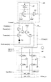
図2は、本実施形態に係る固体撮像装置1に含まれる入射光総量監視部20,画素部Pm,nおよび保持回路Hnそれぞれの回路構成を示す図である。なお、この図では、M×N個の画素部P1,1〜PM,Nのうち代表して画素部Pm,nが示され、N個の保持回路H1〜HNのうち代表して保持回路Hnが示されている。M×N個の画素部P1,1〜PM,Nに対して1個の入射光総量監視部20が設けられている。また、各列のM個の画素部P1,n〜PM,nに対して1個の保持回路Hnが設けられている。
2, the incident light
入射光総量監視部20は、積分回路21および比較回路22を含む。また、積分回路21は、アンプA20,容量素子C20およびスイッチSW20を有する。アンプA20の反転入力端子は、配線Lresetを介して画素部P1,1〜PM,Nそれぞれの放電用トランジスタT1のドレイン端子に接続されている。アンプA20の非反転入力端子は、バイアス電位Vb1に接続されている。このバイアス電位Vb1は、画素部P1,1〜PM,Nそれぞれの増幅用トランジスタT3のゲート端子に形成された寄生容量部の電荷を初期化し得る電位である。アンプA20の反転入力端子と出力端子との間に、互いに並列的に接続された容量素子C20およびスイッチSW20が設けられている。比較回路22は、アンプA20の出力端子から出力される電圧値と基準電圧値Vrefとを大小比較して、当該比較結果を表す信号を入射光総量信号として出力する。この入射光総量信号のレベルに応じてスイッチSW20は開閉制御される。
The incident light total
この入射光総量監視部20では、スイッチSW20が開いていると、画素部P1,1〜PM,Nそれぞれから配線Lresetを経てアンプA20の反転入力端子に入力された電荷が容量素子C20に蓄積されていき、その蓄積電荷量に応じた電圧値がアンプA20の出力端子から出力される。アンプA20の出力端子から出力された電圧値は比較回路22により基準電圧値Vrefとを大小比較され、当該比較結果を表す信号が入射光総量信号として出力される。
In the incident light total
容量素子C20に電荷が蓄積されていくに従い、やがて、アンプA20の出力端子から出力される電圧値と基準電圧値Vrefとの大小関係が逆転して、入射光総量信号のレベルが変化し、これに応じてスイッチSW20が閉じる。スイッチSW20が閉じると、容量素子C20が放電され、アンプA20の出力端子から出力される電圧値が初期化され、アンプA20の出力端子から出力される電圧値と基準電圧値Vrefとの大小関係が再び逆転して、入射光総量信号のレベルが再び変化し、これに応じてスイッチSW20が開く。このように、入射光総量信号は、レベルが時間的に変化するパルス信号となり、そのパルスの繰返し周波数は、アンプA20の反転入力端子への電荷流入の速度(電流値)を表す。 According charge in the capacitor C 20 is accumulated, finally, the magnitude relationship between the voltage value and the reference voltage value Vref output from the output terminal of the amplifier A 20 is reversed, the level of the incident light amount signal changes Accordingly, the switch SW 20 is closed. When the switch SW 20 is closed, the capacitive element C 20 is discharged, the voltage value output from the output terminal of the amplifier A 20 is initialized, and the voltage value output from the output terminal of the amplifier A 20 and the reference voltage value Vref Are reversed again, the level of the incident light total amount signal changes again, and the switch SW 20 is opened accordingly. Thus, the incident light amount signal level becomes time varying pulse signal, the repetition frequency of the pulses represents the rate of charge flow into the inverting input terminal of the amplifier A 20 (current value).
画素部Pm,nは、APS方式のものであって、フォトダイオードPDおよび5個のMOSトランジスタT1〜T5を含む。この図に示されるように、放電用トランジスタT1,転送用トランジスタT2およびフォトダイオードPDは順に直列的に接続されていて、入射光総量監視部20のアンプA20の反転入力端子がトランジスタT1のドレイン端子に接続され、フォトダイオードPDのアノ−ド端子が接地されている。
The pixel portion P m, n is of the APS system and includes a photodiode PD and five MOS transistors T1 to T5. As shown in this figure, the discharge transistor T1, the transfer transistor T2, and the photodiode PD are sequentially connected in series, and the inverting input terminal of the amplifier A 20 of the incident light total
増幅用トランジスタT3および選択用トランジスタT4は直列的に接続されていて、基準電圧Vb2がトランジスタT3のドレイン端子に入力され、トランジスタT4のソース端子が配線Vline(n)に接続されている。トランジスタT1とトランジスタT2との接続点は、トランジスタT5を介してトランジスタT3のゲート端子に接続されている。また、配線Vline(n)には定電流源が接続されている。 The amplification transistor T3 and the selection transistor T4 are connected in series, the reference voltage Vb2 is input to the drain terminal of the transistor T3, and the source terminal of the transistor T4 is connected to the wiring Vline (n). A connection point between the transistor T1 and the transistor T2 is connected to the gate terminal of the transistor T3 through the transistor T5. A constant current source is connected to the wiring Vline (n).
Reset(m)信号がトランジスタT1のゲート端子に入力され、Trans(m)信号がトランジスタT2のゲート端子に入力され、Address(m)信号がトランジスタT4のゲート端子に入力され、また、Hold(m)信号がトランジスタT5のゲート端子に入力される。これらReset(m)信号,Trans(m)信号,Address(m)信号およびHold(m)信号は、制御部70による制御の下に行選択部30から出力され、第m行のN個の画素部Pm,1〜Pm,Nに対して共通に入力される。
The Reset (m) signal is input to the gate terminal of the transistor T1, the Trans (m) signal is input to the gate terminal of the transistor T2, the Address (m) signal is input to the gate terminal of the transistor T4, and Hold (m ) Signal is input to the gate terminal of the transistor T5. These Reset (m) signal, Trans (m) signal, Address (m) signal, and Hold (m) signal are output from the
画素部P1,1〜PM,N全体について、動作シーケンスは以下の三通りに区別される。すなわち、
1)入射光量監視期間(図4中の時刻t1以前)
2)電荷蓄積動作期間(図4中の時刻t1〜t3)
3)読み出し出力期間(図4中の時刻t3以降)
である。このうち、上記1)、2)については、全画素部P1,1〜PM,N全体が同時に動作を開始・終了する。また、3)については単位にて第1行から第M行まで順次動作が繰り返されるものである。この1)〜3)の動作原理を前提に以下に説明を行う。
With respect to the entire pixel units P 1,1 to P M, N , the operation sequence is distinguished in the following three ways. That is,
1) Incident light quantity monitoring period (before time t1 in FIG. 4)
2) Charge accumulation operation period (times t1 to t3 in FIG. 4)
3) Reading output period (after time t3 in FIG. 4)
It is. Among these, for the above 1) and 2), all the pixel portions P 1,1 to P M, N start and end simultaneously. As for 3), the operation is sequentially repeated from the first row to the M-th row in units. The following description will be made on the premise of the operating principles 1) to 3).
入射光総量監視部20のアンプA20の非反転入力端子には、増幅用トランジスタT3のゲート端子に形成された寄生容量部の電荷を初期化する為のバイアス電位Vb1が入力されており、アンプA20の反転入力端子は、非反転入力端子に対してイマジナリショートの関係にあるので、同じくバイアス電位Vb1となっている。したがって、Reset(m)信号およびTrans(m)信号がハイレベルであるとき、フォトダイオードPDの接合容量部(電荷蓄積部)が放電され、さらに、Hold(m)信号もハイレベルであると、トランジスタT3のゲート端子に形成された寄生容量部の電荷が放電される。上記1)の入射光量監視期間においては、常時Reset(m)信号およびTrans(m)信号がハイレベルであり、フォトダイオード全体の光電流がまとめてアンプA20の反転入力端子を介し容量素子C20に流れ続ける。
The non-inverting input terminal of the amplifier A 20 of the incident light
その後に、上記2)の電荷蓄積動作期間に入り、全画素部全体のReset(m)信号,Trans(m)信号およびHold(m)信号がローレベルになると、フォトダイオードPDで発生した電荷は接合容量部に蓄積されていく。電荷蓄積動作期間の最後に、Trans(m)信号およびHold(m)信号が短期間のみ、一斉にハイレベルとなり、フォトダイオード内の電荷がトランジスタT3のゲート容量に瞬時に転送される。 After that, when the charge accumulation operation period of 2) is entered and the Reset (m) signal, Trans (m) signal, and Hold (m) signal of all the pixel portions become low level, the charge generated in the photodiode PD is It accumulates in the junction capacitor. At the end of the charge accumulation operation period, the Trans (m) signal and the Hold (m) signal are simultaneously set to the high level only for a short period, and the charge in the photodiode is instantaneously transferred to the gate capacitance of the transistor T3.
この後、3)の各行読み出し期間に入ると、選択された行のN個の画素部のHold(m)信号がローレベルであって、Address(m)信号がハイレベルであると、画素部Pm,nから配線Vline(n)へノイズ成分が出力される。そして、選択された行のN個の画素部のTrans(m)信号,Hold(m)信号およびAddress(m)信号がハイレベルになると、フォトダイオードPDの接合容量部に蓄積されている電荷の量に応じた電圧値が配線Vline(n)へ信号成分として出力される。 Thereafter, when each row readout period of 3) is entered, if the Hold (m) signal of the N pixel portions of the selected row is at a low level and the Address (m) signal is at a high level, the pixel portion A noise component is output from P m, n to the wiring Vline (n). When the Trans (m) signal, Hold (m) signal, and Address (m) signal of the N pixel portions in the selected row become high level, the charge accumulated in the junction capacitance portion of the photodiode PD is reduced. A voltage value corresponding to the amount is output as a signal component to the wiring Vline (n).
保持回路Hnは、2つの容量素子C1,C2、および、4つのスイッチSW11,SW12,SW21,SW22を含む。このホールド回路Hnでは、スイッチSW11およびスイッチSW12は、直列的に接続されて配線Vline(n)と配線Hline_sとの間に設けられ、容量素子C1の一端は、スイッチSW11とスイッチSW12との間の接続点に接続され、容量素子C1の他端は接地されている。また、スイッチSW21およびスイッチSW22は、直列的に接続されて配線Vline(n)と配線Hline_nとの間に設けられ、容量素子C2の一端は、スイッチSW21とスイッチSW22との間の接続点に接続され、容量素子C2の他端は接地されている。 The holding circuit H n includes two capacitive elements C 1 and C 2 , and four switches SW 11 , SW 12 , SW 21 , and SW 22 . In the holding circuit H n, the switch SW 11 and the switch SW 12 is provided between the serially connected to the wiring Vline (n) and the wiring Hline_s, one terminal of the capacitance C 1, the switch SW 11 and the switch is connected to the connection point between the SW 12, the other end of the capacitive element C 1 is grounded. The switch SW 21 and the switch SW 22 are connected in series and are provided between the wiring Vline (n) and the wiring Hline_n, and one end of the capacitor C 2 is between the switch SW 21 and the switch SW 22. is connected to the connection point, the other end of the capacitive element C 2 is grounded.
このホールド回路Hnでは、スイッチSW11は、制御部70から供給されるset_s信号のレベルに応じて開閉する。スイッチSW21は、制御部70から供給されるset_n信号のレベルに応じて開閉する。set_s信号およびset_n信号は、N個のホールド回路H1〜HNに対して共通に入力される。スイッチSW12,SW22は、制御部70から供給されるhshiht(n)信号のレベルに応じて開閉する。
In the holding circuit H n, the switch SW 11 is opened and closed according to the level of set_s signal supplied from the
このホールド回路Hnでは、set_n信号がハイレベルからローレベルに転じてスイッチSW21が開くときに画素部Pm,nから配線Vline(n)へ出力されていたノイズ成分が、それ以降、容量素子C2により電圧値out_n(n)として保持される。set_s信号がハイレベルからローレベルに転じてスイッチSW11が開くときに画素部Pm,nから配線Vline(n)へ出力されていた信号成分が、それ以降、容量素子C1により電圧値out_s(n)として保持される。そして、hshiht(n)信号がハイレベルになると、スイッチSW12が閉じて、容量素子C1により保持されていた電圧値out_s(n)が配線Hline_sへ出力され、また、スイッチSW22が閉じて、容量素子C2により保持されていた電圧値out_n(n)が配線Hline_nへ出力される。これら電圧値out_s(n)と電圧値out_n(n)との差が、画素部Pm,nのフォトダイオードPDで発生した電荷の量に応じた電圧値を表す。 In the hold circuit H n , the noise component output from the pixel unit P m, n to the wiring Vline (n) when the set_n signal changes from the high level to the low level and the switch SW 21 is opened is the capacitance thereafter. It is held as a voltage value out_n (n) by the element C 2. set_s signal pixel unit P m when the switch SW 11 is opened in turn to a low level from the high level, the signal component being output from the n to the wiring Vline (n) is, thereafter, the voltage value by the capacitance element C 1 out_s held as (n). When the hshiht (n) signal becomes high level, the switch SW 12 is closed, the voltage value out_s (n) held by the capacitive element C 1 is output to the wiring Hline_s, and the switch SW 22 is closed. , the voltage value has been held by the capacitor element C 2 out_n (n) is output to the wiring Hline_n. A difference between the voltage value out_s (n) and the voltage value out_n (n) represents a voltage value corresponding to the amount of charge generated in the photodiode PD of the pixel portion Pm , n .
図3は、本実施形態に係る固体撮像装置1に含まれる差演算回路61の回路構成を示す図である。この図に示されるように、差演算回路61は、アンプA64〜A66、スイッチSW64、SW65、および、抵抗器R1〜R4を含む。アンプA66の反転入力端子は、抵抗器R1を介してバッファアンプA64の出力端子と接続され、抵抗器R3を介して自己の出力端子と接続されている。アンプA66の非反転入力端子は、抵抗器R2を介してバッファアンプA65の出力端子と接続され、抵抗器R4を介して接地電位と接続されている。アンプA66の出力端子は画素用AD変換回路62の入力端子と接続されている。バッファアンプA64の入力端子は、配線Hline_sを介してN個の保持回路H1〜HNと接続され、スイッチSW64を介して接地電位と接続されている。バッファアンプA65の入力端子は、配線Hline_nを介してN個の保持回路H1〜HNと接続され、スイッチSW65を介して接地電位と接続されている。
FIG. 3 is a diagram illustrating a circuit configuration of the
差演算回路61のスイッチSW64,SW65は、hreset信号により制御されて開閉動作する。スイッチSW64が閉じることで、バッファアンプA64の入力端子に入力される電圧値がリセットされる。スイッチSW65が閉じることで、バッファアンプA65の入力端子に入力される電圧値がリセットされる。スイッチSW64,SW65が開いているときに、N個の保持回路H1〜HNのうちの何れかの保持回路Hnから配線Hline_s,Hline_nへ出力された電圧値out_s(n),out_n(n)が、バッファアンプA64,A65の入力端子に入力される。バッファアンプA64,A65それぞれの増幅率を1とし、4個の抵抗器R1〜R4それぞれの抵抗値が互いに等しいとすると、差演算回路61の出力端子から出力される電圧値は、配線Hline_sおよび配線Hline_nそれぞれを経て入力される電圧値の差を表す。
The switches SW 64 and SW 65 of the
次に、本実施形態に係る固体撮像装置1の動作の一例について説明する。図4は、本実施形態に係る固体撮像装置1の動作の一例を示すタイミングチャートである。固体撮像装置1は、制御部70による制御の下に動作する。この図には、上から順に、 (a) 固体撮像素子1に入射する光の強度、(b) 入射光総量監視部20の積分回路21から出力される電圧値、 (c) 入射光総量監視部20から出力される入射光総量信号、(d) 制御部70から出力される電荷蓄積動作制御信号、(e) 出力部60から出力される信号、が示されている。なお、この図では、受光部10の第m行についてAD変換回路62から出力されるデジタル値(画素データ)をDdata(m)と表している。
Next, an example of the operation of the solid-
固体撮像素子1に電源が投入された直後の一定期間に、制御部70から出力される電荷蓄積動作制御信号がハイレベルとされる。そして、この電荷蓄積動作制御信号がローレベルに転じた後に、受光部10から電圧保持部50,差演算回路61,AD変換回路62およびスイッチSW63を経て1フレーム分の画素データが出力部60から出力される。このとき出力される画素データは無意味なものであるが、電源投入後の一定期間に亘って電荷蓄積動作制御信号がハイレベルとされることにより、受光部10の各画素部Pm,nや他の回路がリセットされ、その後の正常動作が可能となる。
The charge accumulation operation control signal output from the
また、このリセットにより、行選択部30から各画素部Pm,nに供給されるReset(m)信号,Trans(m)信号およびHold(m)信号がともにハイレベルとされて、トランジスタT1,T2,T5がオン状態となっていて、フォトダイオードPDの接合容量部(電荷蓄積部)が放電され、トランジスタT3のゲート端子の電位がリセットされる。また、入射光総量監視部20の積分回路21に含まれるスイッチSW20は、一定期間だけ閉じた後に開く。
In addition, by this reset, the Reset (m) signal, the Trans (m) signal, and the Hold (m) signal supplied from the
その後、固体撮像素子1に光が入射していない期間では、受光部10の各画素部Pm,nに含まれるフォトダイオードPDでは暗電流が発生する。その暗電流は、各画素部Pm,nに含まれるトランジスタT1,T2および配線Lresetを経て、入射光総量監視部20の積分回路21に入力され、容量素子C20に電荷が蓄積されていく。これにより積分回路21から出力される電圧値は次第に増加していくか、その増加速度は遅い。
Thereafter, during a period in which no light is incident on the solid-
したがって、固体撮像素子1に光が入射していない期間では、入射光総量監視部20から出力される入射光総量信号のパルス間隔は広い。そして、制御部70において、入射光総量信号のパルス間隔が所定値より広いと判定され、固体撮像素子1に光が入射していない(または、入射光量が一定レベルより小さい)と判断されて、電荷蓄積動作制御信号がローレベルのままとされる。
Therefore, the pulse interval of the incident light total amount signal output from the incident light total
やがて、固体撮像素子1に光が入射し始めると、受光部10の各画素部Pm,nに含まれるフォトダイオードPDで発生した電荷は、各画素部Pm,nに含まれるトランジスタT1,T2および配線Lresetを経て、入射光総量監視部20の積分回路21に入力され、容量素子C20に電荷が蓄積されていく。これにより積分回路21から出力される電圧値は次第に増加していくか、その増加速度は入射光量に応じたものとなる。
Eventually, when light begins to enter the solid-
したがって、固体撮像素子1に光が入射し始めると、入射光総量監視部20から出力される入射光総量信号のパルス間隔は狭くなる。そして、制御部70において、入射光総量信号のパルス間隔が所定値より狭いと判定され、固体撮像素子1に光が入射している(または、入射光量が一定レベル以上である)と判断されて、時刻t1に電荷蓄積動作制御信号がハイレベルに転じる。
Therefore, when light begins to enter the solid-
そして、電荷蓄積動作制御信号がハイレベルに転じた時刻t1から、電荷蓄積動作制御信号がローレベルに転じる時刻t2までの期間、受光部10の各画素部Pm,nでは、Reset(m)信号,Trans(m)信号およびHold(m)信号がローレベルになって、トランジスタT1,T2,T5がオフ状態となり、フォトダイオードPDで発生した電荷は接合容量部に蓄積されていく。
Then, during a period from time t1 when the charge accumulation operation control signal changes to high level to time t2 when the charge accumulation operation control signal changes to low level, each pixel unit Pm, n of the
なお、入射光量を予め予測できる場合には、その予測値に基づいて電荷蓄積時間(すなわち、電荷蓄積動作制御信号がハイレベルとされる期間t 1 〜t 2 )を適正値に設定してもよい。
Na us, if it can be predicted in advance the amount of incident light, set charge accumulation time based on the predicted value (i.e., the charge accumulation operation control signal period t 1 ~t 2 is a high level) to the proper value Also good.
電荷蓄積動作制御信号がローレベルに転じた時刻t2から時刻t3までの期間、受光部10の各画素部Pm,nでは、Reset(m)信号およびAddress(m)信号がローレベルとなって、トランジスタT1,T4がオフ状態となり、また、Trans(m)信号およびHold(m)信号がハイレベルになって、トランジスタT2,T5がオン状態となる。これにより、それまでに接合容量部に蓄積されていた電荷は、トランジスタT2,T5を経て、トランジスタT3のゲート端子に移動してホールドされる。ただし、トランジスタT4がオフ状態であるので、電荷蓄積量に応じた電圧値が各画素部Pm,nから配線Vline(n)へ出力されることは無い。
In the period from time t 2 to time t 3 when the charge accumulation operation control signal has changed to low level, the Reset (m) signal and Address (m) signal are at low level in each pixel unit P m, n of the
続く時刻t3から時刻t4までの期間に、受光部10の第1行にあるN個の画素部P1,1〜P1,Nにおける電荷蓄積量に応じたN個の画素データDdata(1)が出力部60から出力される。具体的には、受光部10の第1行においてのみ、Address(1)信号がハイレベルとなり、トランジスタT4がオン状態となって、第1行にある各画素部P1,nにおける電荷蓄積量に応じた電圧値が、配線Vline(n)へ出力され、電圧保持部50の保持回路Hnにより保持される。そして、各保持回路Hnから順次に出力された電圧値は差演算回路61を経てAD変換回路62に入力されてAD変換され、AD変換回路62からスイッチSW63を経て順次にN個の画素データDdata(1)が出力される。
In the subsequent period from time t 3 to time t 4 , N pixel data Ddata (according to the charge accumulation amount in the N pixel portions P 1,1 to P 1, N in the first row of the
続く時刻t4から時刻t5までの期間に、受光部10の第2行にあるN個の画素部P2,1〜P2,Nにおける電荷蓄積量に応じたN個の画素データDdata(2)が出力部60から出力される。具体的には、受光部10の第2行においてのみ、Address(2)信号がハイレベルとなり、トランジスタT4がオン状態となって、第2行にある各画素部P2,nにおける電荷蓄積量に応じた電圧値が、配線Vline(n)へ出力され、電圧保持部50の保持回路Hnにより保持される。そして、各保持回路Hnから順次に出力された電圧値は差演算回路61を経てAD変換回路62に入力されてAD変換され、AD変換回路62からスイッチSW63を経て順次にN個の画素データDdata(2)が出力される。
In the subsequent period from time t 4 to time t 5 , N pixel data Ddata (according to the charge accumulation amount in the N pixel portions P 2, 1 to P 2, N in the second row of the
更に続く時刻t5から時刻t6までの期間に、受光部10の第3行にあるN個の画素部P3,1〜P3,Nにおける電荷蓄積量に応じたN個の画素データDdata(3)が出力部60から出力される。具体的には、受光部10の第3行においてのみ、Address(3)信号がハイレベルとなり、トランジスタT4がオン状態となって、第3行にある各画素部P3,nにおける電荷蓄積量に応じた電圧値が、配線Vline(n)へ出力され、電圧保持部50の保持回路Hnにより保持される。そして、各保持回路Hnから順次に出力された電圧値は差演算回路61を経てAD変換回路62に入力されてAD変換され、AD変換回路62からスイッチSW63を経て順次にN個の画素データDdata(3)が出力される。
Further, during the period from time t 5 to time t 6 , N pieces of pixel data Ddata corresponding to the charge accumulation amount in the N pieces of pixel parts P 3,1 to P 3, N in the third row of the
以降も同様にして、受光部10の第4行から第M行まで順次に、第m行にあるN個の画素部Pm,1〜Pm,Nにおける電荷蓄積量に応じたN個の画素データDdata(m)が出力部60から出力される。このようにして、受光部10から電圧保持部50,差演算回路61,AD変換回路62およびスイッチSW63を経て1フレーム分の画素データDdata(1)〜Ddata(M)が出力部60から出力される。そして、1フレーム分の画素データが出力された後、再び、時刻t1前と同じ状態に戻る。
In the same manner thereafter, N light sources corresponding to the charge accumulation amounts in the N pixel portions P m, 1 to P m, N in the m-th row are sequentially formed from the fourth row to the M-th row of the
このように、本実施形態に係る固体撮像装置1では、受光部10への入射光量を監視する入射光総量監視部20が設けられていて、入射光総量監視部20から出力される入射光総量信号に基づいて、受光部10に光が入射しているか否か(または、入射光量が一定レベル以上であるか否か)が判断される。そして、受光部10に光が入射している(または、入射光量が一定レベル以上である)と判断されたときに、受光部10の画素部P1,1〜PM,Nそれぞれにおける電荷蓄積量に応じた画素データDdata(1)〜Ddata(M)が出力部60から出力される。すなわち、受光部10から出力部60へ到る画素データの読出動作、その中でも特にAD変換回路62におけるAD変換動作は、受光部10への光入射があったときのみでよい。したがって、本実施形態に係る固体撮像装置1は、画素数の増加や撮像の高速化を図る場合であっても、消費電力の増大を抑制することができる。
Thus, in the solid-
本実施形態に係る固体撮像装置1は、例えば以下のような用途の際に効果を発揮することができる。すなわち、固体撮像装置1は、受光部10の受光面上にシンチレータが設けられることで、入射したX線をシンチレータにより可視光に変換して、その可視光を受光部10のフォトダイオードで受光することができ、これにより、入射したX線を撮像することができる。このようなシンチレータが設けられた固体撮像装置1は、口腔内におけるX線撮像に用いられる。
The solid-
固体撮像装置1が口腔内におけるX線撮像に用いられる場合、撮像すべきX線の入射期間が極めて短く、固体撮像装置1はX線入射タイミングを捉えて該X線を撮像しなければならない。そこで、固体撮像装置1は、入射光総量監視部20によりX線入射を検知する。そして、固体撮像装置1は、X線入射を検知したら、受光部10,電圧保持部50,差演算回路61およびAD変換回路62により画素データを読み出す。このようにすることにより、固体撮像装置1は、X線入射タイミングを捉えて該X線を撮像することができる。
When the solid-
このように、固体撮像装置1が口腔内におけるX線撮像に用いられる場合、X線入射前にはAD変換回路62を休止することができ、X線入射時のみAD変換回路62を動作させればよい。したがって、この固体撮像装置1は、画素数の増加や撮像の高速化を図る場合であっても、消費電力の増大を抑制することができる。
Thus, when the solid-
また、固体撮像装置1が口腔内におけるX線撮像に用いられる場合、画素データおよび入射光総量信号を共通の出力信号線Loutへ出力するのが好適であり、また、これらのデータをシリアルデータとして出力するのも好適である。これらの場合には、これらのデータを出力するための配線の本数を削減することができ、信頼性を向上させることができる。
When the solid-
さらに、固体撮像装置1は、光入射を検知した後に、受光部10のM×N個の画素部P1,1〜PM,Nそれぞれにおいて同一期間にフォトダイオードPDで発生した電荷を電荷蓄積部により蓄積することができ、その電荷蓄積の後に、各画素部Pm,nについて画素データを順次に出力部60から出力することができる。したがって、入射光量の時間的な変化が速い場合であっても、全ての画素部において同一期間の入射光量を捉えることができ、高精度の撮像を行うことができる。
Furthermore, the solid-
本発明は、上記実施形態に限定されるものではなく、種々の変形が可能である。例えば、上記実施形態では制御部70が電荷蓄積動作制御信号を生成したが、入射光総量信号に基づいて電荷蓄積動作制御信号を生成する外部機器を固体撮像装置とは別個に設けてもよい。この場合、固体撮像装置の出力部から外部機器へ入射光総量信号が出力され、その出力された入射光総量信号に基づいて外部機器により電荷蓄積動作制御信号が生成され、その生成された電荷蓄積動作制御信号が外部機器から固体撮像装置へ与えられる。
The present invention is not limited to the above embodiment, and various modifications can be made. For example, in the above embodiment, the
このようにすることにより、入射光総量信号と閾値との大小比較に基づく光入射検知の際に、その閾値を外部機器において柔軟に調整することができる。また、電荷蓄積動作制御信号が電荷蓄積を指示する期間(すなわち、各画素部においてフォトダイオードで発生した電荷を電荷蓄積部により蓄積する期間)を外部機器において柔軟に調整することができ、幅広い入射光量レンジに容易に対応することができる。 By doing so, the threshold value can be flexibly adjusted in the external device when detecting the light incidence based on the magnitude comparison between the incident light total amount signal and the threshold value. In addition, the period during which the charge accumulation operation control signal directs charge accumulation (that is, the period during which charges generated by the photodiode in each pixel portion are accumulated by the charge accumulation portion) can be flexibly adjusted in an external device, and a wide range of incidence It can easily cope with the light quantity range.
また、入射光総量監視部20については、図5または図6に示される変形例の構成も可能である。図5に示される入射光総量監視部20Aは、アンプA20,容量素子C20およびスイッチSW20を有する。アンプA20の反転入力端子は、配線Lresetを介して画素部P1,1〜PM,Nそれぞれの放電用トランジスタT1のドレイン端子に接続されている。アンプA20の非反転入力端子は、バイアス電位Vb1に接続されている。このバイアス電位Vb1は、画素部P1,1〜PM,Nそれぞれの増幅用トランジスタT3のゲート端子に形成された寄生容量部の電荷を初期化し得る電位である。アンプA20の反転入力端子と出力端子との間に、互いに並列的に接続された容量素子C20およびスイッチSW20が設けられている。スイッチSW20は、制御部70Aにより制御されて、一定周期で開閉する。そして、入射光総量監視部20Aは、アンプA20の出力端子からの出力信号を入射光総量信号として出力する。
Further, the incident light total
この入射光総量監視部20Aでは、スイッチSW20の一定周期の開閉に応じて、アンプA20の出力端子から出力される電圧値は増減を繰り返す。すなわち、スイッチSW20が閉じると、アンプA20の出力端子から出力される電圧値は初期化され、スイッチSW20が開いている期間に、アンプA20の出力端子から出力される電圧値は変化する。そのときの出力電圧値の変化速度は、アンプA20の反転入力端子への電荷流入の速度(電流値)を表す。また、スイッチSW20が開いている期間は一定であり、スイッチSW20が閉じている期間も一定である。したがって、アンプA20の出力端子から出力される入射光総量信号の各三角波のピーク値は、受光部10に入射する光の総量を表す。
In the incident light total
図6に示される入射光総量監視部20Bは、アンプA20および抵抗器R20を有する。アンプA20の反転入力端子は、配線Lresetを介して画素部P1,1〜PM,Nそれぞれの放電用トランジスタT1のドレイン端子に接続されている。アンプA20の非反転入力端子は、バイアス電位Vb1に接続されている。このバイアス電位Vb1は、画素部P1,1〜PM,Nそれぞれの増幅用トランジスタT3のゲート端子に形成された寄生容量部の電荷を初期化し得る電位である。アンプA20の反転入力端子と出力端子との間に抵抗器R20が設けられている。この入射光総量監視部20Bでは、アンプA20の反転入力端子に入力する電流値に応じた電圧値がアンプA20の出力端子から入射光総量信号として出力される。アンプA20から出力される入射光総量信号は、受光部10に入射する光の総量を表す。
Incident light
1…固体撮像装置、10…受光部、20…入射光総量監視部、21…積分回路、22…比較回路、30…行選択部、40…列選択部、50…電圧保持部、60…出力部、61…差演算回路、62…AD変換回路、70…制御部、P1,1〜PM,N…画素部。
DESCRIPTION OF
Claims (5)
前記複数の画素部それぞれにおける電荷蓄積動作の後に、前記複数の画素部それぞれの前記選択用トランジスタから出力される電圧値に応じたデジタル値を出力する出力部と、
第1入力端子,第2入力端子および出力端子を有するアンプを含み、前記複数の画素部それぞれの前記放電用トランジスタに前記アンプの前記第1入力端子が接続され、前記複数の画素部それぞれの前記寄生容量部の電荷を初期化する為のバイアス電位に前記アンプの前記第2入力端子が接続され、前記アンプの前記出力端子からの出力信号に基づいて、前記複数の画素部それぞれの前記フォトダイオードに入射する光の総量を表す入射光総量信号を出力する入射光総量監視部と、
を備えることを特徴とする固体撮像装置。 Generated by a photodiode that generates an amount of charge corresponding to the amount of incident light, an amplifying transistor that outputs a voltage value corresponding to the amount of charge stored in the parasitic capacitance formed at the gate terminal, and the photodiode A transfer transistor that transfers the generated charge to the gate terminal of the amplification transistor, a discharge transistor that initializes the charge of the parasitic capacitance section, and a selection that selectively outputs a voltage value output from the amplification transistor A plurality of pixel portions each having a transistor for use, and a light receiving portion that accumulates charges generated in the photodiodes in each of the plurality of pixel portions in the parasitic capacitance portion during a period indicated by a charge accumulation operation control signal,
An output unit that outputs a digital value corresponding to a voltage value output from the selection transistor of each of the plurality of pixel units after the charge accumulation operation in each of the plurality of pixel units;
An amplifier having a first input terminal, a second input terminal, and an output terminal, wherein the first input terminal of the amplifier is connected to the discharge transistor of each of the plurality of pixel units, and each of the plurality of pixel units The second input terminal of the amplifier is connected to a bias potential for initializing the charge of the parasitic capacitance unit, and the photodiodes of each of the plurality of pixel units are based on an output signal from the output terminal of the amplifier. An incident light total amount monitoring unit for outputting an incident light total amount signal indicating the total amount of light incident on
A solid-state imaging device comprising:
前記アンプの前記第1入力端子と前記出力端子との間に設けられた容量素子およびスイッチと、前記アンプの前記出力端子から出力される電圧値と基準電圧値とを大小比較して当該比較結果を表す信号を前記入射光総量信号として出力する比較回路とを更に含み、
前記スイッチが前記入射光総量信号のレベルに応じて開閉制御される、
ことを特徴とする請求項1記載の固体撮像装置。 The incident light total amount monitoring unit,
A comparison result obtained by comparing the capacitance value and the switch provided between the first input terminal and the output terminal of the amplifier with a voltage value output from the output terminal of the amplifier and a reference voltage value. And a comparison circuit that outputs a signal representing the total incident light amount signal,
The switch is controlled to open and close according to the level of the incident light total amount signal.
The solid-state imaging device according to claim 1.
前記アンプの前記第1入力端子と前記出力端子との間に設けられた容量素子およびスイッチを更に含み、
前記スイッチが一定周期で開閉制御され、
前記アンプの前記出力端子からの出力信号を前記入射光総量信号として出力する、
ことを特徴とする請求項1記載の固体撮像装置。 The incident light total amount monitoring unit,
A capacitor and a switch provided between the first input terminal and the output terminal of the amplifier;
The switch is controlled to open and close at regular intervals,
Output an output signal from the output terminal of the amplifier as the total incident light signal,
The solid-state imaging device according to claim 1.
前記アンプの前記第1入力端子と前記出力端子との間に設けられた抵抗器を更に含み、
前記アンプの前記出力端子からの出力信号を前記入射光総量信号として出力する、
ことを特徴とする請求項1記載の固体撮像装置。 The incident light total amount monitoring unit,
A resistor provided between the first input terminal and the output terminal of the amplifier;
Output an output signal from the output terminal of the amplifier as the total incident light signal,
The solid-state imaging device according to claim 1.
Priority Applications (1)
| Application Number | Priority Date | Filing Date | Title |
|---|---|---|---|
| JP2006259231A JP4833010B2 (en) | 2006-09-25 | 2006-09-25 | Solid-state imaging device |
Applications Claiming Priority (1)
| Application Number | Priority Date | Filing Date | Title |
|---|---|---|---|
| JP2006259231A JP4833010B2 (en) | 2006-09-25 | 2006-09-25 | Solid-state imaging device |
Publications (2)
| Publication Number | Publication Date |
|---|---|
| JP2008079250A JP2008079250A (en) | 2008-04-03 |
| JP4833010B2 true JP4833010B2 (en) | 2011-12-07 |
Family
ID=39350783
Family Applications (1)
| Application Number | Title | Priority Date | Filing Date |
|---|---|---|---|
| JP2006259231A Expired - Fee Related JP4833010B2 (en) | 2006-09-25 | 2006-09-25 | Solid-state imaging device |
Country Status (1)
| Country | Link |
|---|---|
| JP (1) | JP4833010B2 (en) |
Cited By (2)
| Publication number | Priority date | Publication date | Assignee | Title |
|---|---|---|---|---|
| CN104247404A (en) * | 2012-05-01 | 2014-12-24 | 索尼公司 | Image sensor, and control method for image sensor |
| CN107018342A (en) * | 2015-12-08 | 2017-08-04 | 台湾积体电路制造股份有限公司 | Image device and its operating method |
Families Citing this family (1)
| Publication number | Priority date | Publication date | Assignee | Title |
|---|---|---|---|---|
| CN106362306B (en) * | 2016-09-30 | 2019-03-15 | 武汉芸禾光电技术有限公司 | A kind of portable multi-channel laser therapeutic system |
Family Cites Families (7)
| Publication number | Priority date | Publication date | Assignee | Title |
|---|---|---|---|---|
| JPH08149376A (en) * | 1994-11-18 | 1996-06-07 | Olympus Optical Co Ltd | Solid-state image pickup device |
| JPH11155847A (en) * | 1997-11-28 | 1999-06-15 | Canon Inc | Radiographic device and driving method |
| JPH11188033A (en) * | 1997-12-26 | 1999-07-13 | Hamamatsu Photonics Kk | Dentistry x-ray image pickup device and its module |
| JP3894534B2 (en) * | 2001-05-16 | 2007-03-22 | キヤノン株式会社 | Imaging apparatus and radiation imaging apparatus |
| JP2005175986A (en) * | 2003-12-12 | 2005-06-30 | Canon Inc | Image input device |
| US7211803B1 (en) * | 2006-04-24 | 2007-05-01 | Eastman Kodak Company | Wireless X-ray detector for a digital radiography system with remote X-ray event detection |
| JP4717786B2 (en) * | 2006-11-21 | 2011-07-06 | 浜松ホトニクス株式会社 | Solid-state imaging device |
-
2006
- 2006-09-25 JP JP2006259231A patent/JP4833010B2/en not_active Expired - Fee Related
Cited By (3)
| Publication number | Priority date | Publication date | Assignee | Title |
|---|---|---|---|---|
| CN104247404A (en) * | 2012-05-01 | 2014-12-24 | 索尼公司 | Image sensor, and control method for image sensor |
| CN104247404B (en) * | 2012-05-01 | 2017-10-24 | 索尼半导体解决方案公司 | Imaging sensor and the control method for imaging sensor |
| CN107018342A (en) * | 2015-12-08 | 2017-08-04 | 台湾积体电路制造股份有限公司 | Image device and its operating method |
Also Published As
| Publication number | Publication date |
|---|---|
| JP2008079250A (en) | 2008-04-03 |
Similar Documents
| Publication | Publication Date | Title |
|---|---|---|
| JP4819561B2 (en) | Solid-state imaging device | |
| US10257452B2 (en) | Solid-state image pickup apparatus, signal processing method for a solid-state image pickup apparatus, and electronic apparatus | |
| KR100737916B1 (en) | Image sensor, and test system and test method for the same | |
| US20040174449A1 (en) | CMOS active pixel with hard and soft reset | |
| US9549138B2 (en) | Imaging device, imaging system, and driving method of imaging device using comparator in analog-to-digital converter | |
| WO2011129143A1 (en) | Solid-state imaging device | |
| JP2003234957A (en) | Solid-state imaging apparatus and its outputting method | |
| US8325258B2 (en) | Solid-state imaging device including imaging photodetecting arrangement and trigger photodetecting arrangement and imaging method | |
| US20050051775A1 (en) | Semiconductor pixel arrays with reduced sensitivity to defects | |
| JP4833010B2 (en) | Solid-state imaging device | |
| JP4800045B2 (en) | Solid-state imaging device | |
| JP4717786B2 (en) | Solid-state imaging device | |
| JP4262020B2 (en) | Photodetector | |
| JP4561646B2 (en) | Driving method of solid-state imaging device | |
| JP4696877B2 (en) | Solid-state imaging device | |
| JP2013229712A (en) | Power supply device, solid-state imaging device, and electronic apparatus |
Legal Events
| Date | Code | Title | Description |
|---|---|---|---|
| A621 | Written request for application examination |
Free format text: JAPANESE INTERMEDIATE CODE: A621 Effective date: 20090609 |
|
| A977 | Report on retrieval |
Free format text: JAPANESE INTERMEDIATE CODE: A971007 Effective date: 20110629 |
|
| A131 | Notification of reasons for refusal |
Free format text: JAPANESE INTERMEDIATE CODE: A131 Effective date: 20110705 |
|
| A521 | Request for written amendment filed |
Free format text: JAPANESE INTERMEDIATE CODE: A523 Effective date: 20110826 |
|
| TRDD | Decision of grant or rejection written | ||
| A01 | Written decision to grant a patent or to grant a registration (utility model) |
Free format text: JAPANESE INTERMEDIATE CODE: A01 Effective date: 20110920 |
|
| A01 | Written decision to grant a patent or to grant a registration (utility model) |
Free format text: JAPANESE INTERMEDIATE CODE: A01 |
|
| A61 | First payment of annual fees (during grant procedure) |
Free format text: JAPANESE INTERMEDIATE CODE: A61 Effective date: 20110921 |
|
| R150 | Certificate of patent or registration of utility model |
Ref document number: 4833010 Country of ref document: JP Free format text: JAPANESE INTERMEDIATE CODE: R150 Free format text: JAPANESE INTERMEDIATE CODE: R150 |
|
| FPAY | Renewal fee payment (event date is renewal date of database) |
Free format text: PAYMENT UNTIL: 20140930 Year of fee payment: 3 |
|
| LAPS | Cancellation because of no payment of annual fees |