JP4832966B2 - refrigerator - Google Patents

refrigerator Download PDF

Info

Publication number
JP4832966B2
JP4832966B2 JP2006169889A JP2006169889A JP4832966B2 JP 4832966 B2 JP4832966 B2 JP 4832966B2 JP 2006169889 A JP2006169889 A JP 2006169889A JP 2006169889 A JP2006169889 A JP 2006169889A JP 4832966 B2 JP4832966 B2 JP 4832966B2
Authority
JP
Japan
Prior art keywords
temperature
switching chamber
temperature switching
refrigerator
cold air
Prior art date
Legal status (The legal status is an assumption and is not a legal conclusion. Google has not performed a legal analysis and makes no representation as to the accuracy of the status listed.)
Active
Application number
JP2006169889A
Other languages
Japanese (ja)
Other versions
JP2008002696A5 (en
JP2008002696A (en
Inventor
泰治 大城
Current Assignee (The listed assignees may be inaccurate. Google has not performed a legal analysis and makes no representation or warranty as to the accuracy of the list.)
Sharp Corp
Original Assignee
Sharp Corp
Priority date (The priority date is an assumption and is not a legal conclusion. Google has not performed a legal analysis and makes no representation as to the accuracy of the date listed.)
Filing date
Publication date
Application filed by Sharp Corp filed Critical Sharp Corp
Priority to JP2006169889A priority Critical patent/JP4832966B2/en
Publication of JP2008002696A publication Critical patent/JP2008002696A/en
Publication of JP2008002696A5 publication Critical patent/JP2008002696A5/ja
Application granted granted Critical
Publication of JP4832966B2 publication Critical patent/JP4832966B2/en
Active legal-status Critical Current
Anticipated expiration legal-status Critical

Links

Images

Description

本発明は、ユーザにより所望の室内温度に切り替えることができる温度切替室を備えた冷蔵庫に関する。   The present invention relates to a refrigerator including a temperature switching chamber that can be switched to a desired room temperature by a user.

冷凍室及び冷蔵室に加えて温度切替室を備えた冷蔵庫が特許文献1に開示されている。この冷蔵庫は、温度切替室に送出される冷気の通路を開閉するダンパ装置と、温度切替室を昇温するヒータとを備えている。これにより、温度切換室の室内温度を使用者の用途に応じて冷凍、冷蔵、パーシャル、チルド等の所望の低温の温度帯に切り替えることができる。   Patent Document 1 discloses a refrigerator that includes a temperature switching chamber in addition to a freezer compartment and a refrigerator compartment. This refrigerator includes a damper device that opens and closes a passage of cool air sent to the temperature switching chamber, and a heater that raises the temperature of the temperature switching chamber. Thereby, the room temperature of the temperature switching chamber can be switched to a desired low temperature range such as freezing, refrigeration, partial, chilled, etc. according to the user's application.

また、特許文献2には温度切替室内にヒータを設け、ヒータの駆動によって温度切替室内を常温よりも高温に維持できる冷蔵庫が特許文献2に開示されている。これにより、加熱物の保温や温調理等を行うことができる。   Patent Document 2 discloses a refrigerator in which a heater is provided in a temperature switching chamber and the temperature switching chamber can be maintained at a temperature higher than room temperature by driving the heater. Thereby, heat insulation of a heating thing, warm cooking, etc. can be performed.

温度切替室は製氷室と左右に並設され、温度切替室及び製氷室の上方に冷蔵室が配される。温度切替室の下方には野菜室が配され、製氷室の下方に製氷室と連通する冷凍室が配されている。冷却器は冷凍室の背後に設けられ、冷却器の冷気は製氷室及び温度切替室に吐出される。製氷室に吐出された冷気は製氷室及び冷凍室を流通した後、冷却器に戻る。温度切替室に吐出された冷気は温度切替室を流通した後、冷却器に戻る。   The temperature switching chamber is arranged side by side with the ice making chamber, and a refrigeration chamber is disposed above the temperature switching chamber and the ice making chamber. A vegetable room is arranged below the temperature switching room, and a freezing room communicating with the ice making room is arranged below the ice making room. The cooler is provided behind the freezer compartment, and the cool air of the cooler is discharged to the ice making chamber and the temperature switching chamber. The cool air discharged into the ice making chamber flows through the ice making chamber and the freezing chamber and then returns to the cooler. The cool air discharged to the temperature switching chamber flows through the temperature switching chamber and then returns to the cooler.

製氷室の背後には冷蔵室ダンパが設けられる。冷蔵室ダンパを開くと、冷却器の冷気が冷蔵室の背後を流通し、冷蔵室に冷気が吐出される。冷蔵室に吐出された冷気は冷蔵室及び野菜室を流通し、冷却器に戻る。
特開平10−288440号公報 特開2006−125705号公報
A refrigeration room damper is provided behind the ice making room. When the refrigerator compartment damper is opened, the cooler cooler flows behind the refrigerator compartment and the cooler is discharged into the refrigerator compartment. The cold air discharged into the refrigerator compartment flows through the refrigerator compartment and the vegetable compartment and returns to the cooler.
Japanese Patent Laid-Open No. 10-288440 JP 2006-125705 A

しかしながら、上記特許文献2に開示される冷蔵庫は製氷室の背後に配された冷蔵室ダンパを介して冷蔵室に冷気が送出される。このため、製氷室の奥行が狭くなり、通常必要な量の氷を貯氷するために製氷室の横幅を広く必要とする。このため、温度切替室の容積が狭くなり、冷蔵庫の利便性が悪い問題があった。   However, in the refrigerator disclosed in Patent Document 2, cold air is sent to the refrigerating room via a refrigerating room damper disposed behind the ice making room. For this reason, the depth of the ice making chamber is narrowed, and the width of the ice making chamber is required to be wide in order to store the ice normally required. For this reason, there was a problem that the volume of the temperature switching chamber was reduced and the convenience of the refrigerator was poor.

本発明は、利便性を向上できる温度切替室を備えた冷蔵庫を提供することを目的とする。   An object of this invention is to provide the refrigerator provided with the temperature switching chamber which can improve the convenience.

上記目的を達成するために本発明の冷蔵庫は、冷却器で生成される冷気が第1冷気通路を流通して冷凍室に送出されるとともに、冷蔵室ダンパを介して第1冷気通路に連通する第2冷気通路を流通して冷蔵室に送出される冷蔵庫において、冷凍温度を含む複数の室内温度に切り替えできる温度切替室と、断熱材から成る縦断熱壁を介して前記温度切替室の側方に配されるとともに前記冷凍室に連通して氷を製氷する製氷室とを備え、
前記冷蔵室の下方に前記冷凍室を配置するとともに、前記温度切替室及び前記製氷室を前記冷蔵室と前記冷凍室との間に配置し、正面投影において前記冷蔵室ダンパと前記縦断熱壁とを重なる位置に配置したことを特徴としている。
In order to achieve the above object, in the refrigerator of the present invention, cold air generated by the cooler flows through the first cold air passage and is sent to the freezer compartment, and communicates with the first cold air passage through the refrigerator compartment damper. In the refrigerator that flows through the second cold air passage and is sent to the refrigerating chamber, a temperature switching chamber that can be switched to a plurality of indoor temperatures including the freezing temperature, and a side of the temperature switching chamber via a vertical heat insulating wall made of a heat insulating material And an ice making chamber that communicates with the freezer and makes ice.
The freezing room is arranged below the refrigerating room, the temperature switching room and the ice making room are arranged between the refrigerating room and the freezing room, and the refrigerating room damper and the vertical heat insulating wall in front projection It has the feature that it has been arranged in the position which overlaps.

この構成によると、冷却器で生成された冷気は第1冷気通路を介して製氷室、冷凍室、温度切替室に導かれて貯蔵物を冷凍保存する。温度切替室と製氷室とを仕切る縦断熱壁の背後に配された冷蔵室ダンパを開くと、第1冷気通路を流通する冷気が第2冷気通路に導かれ、冷蔵室に吐出される。これにより冷蔵室内の貯蔵物が冷蔵保存される。また、温度切替室は冷凍、パーシャル、チルド、冷蔵等に室内温度が切り替えられる。   According to this configuration, the cold air generated by the cooler is guided to the ice making room, the freezing room, and the temperature switching room via the first cold air passage, and the stored items are stored in a frozen state. When the refrigeration chamber damper disposed behind the vertical heat insulating wall that partitions the temperature switching chamber and the ice making chamber is opened, the cold air flowing through the first cold air passage is guided to the second cold air passage and discharged into the cold storage chamber. Thereby, the stored item in the refrigerator compartment is refrigerated. In the temperature switching chamber, the room temperature can be switched to refrigeration, partial, chilled, refrigerated, or the like.

また本発明は上記構成の冷蔵庫において、前記温度切替室を加熱する加熱装置を備え、前記冷却器による冷却及び前記加熱装置による加熱によって前記温度切替室を貯蔵物の冷凍保存を含む冷却保存を行う低温側と、常温よりも高温の高温側に切り替えできることを特徴としている。   In the refrigerator having the above-described configuration, the present invention includes a heating device that heats the temperature switching chamber, and the temperature switching chamber is cooled and stored in a refrigerator including frozen storage by cooling with the cooler and heating by the heating device. It is characterized in that it can be switched between a low temperature side and a high temperature side that is higher than normal temperature.

この構成によると、温度切替室は低温側に切り替えられると冷却器から冷気が導入され、冷凍、パーシャル、チルド、冷蔵等の低温室となる。これにより、貯蔵物を冷却保存できる。温度切替室は高温側に切り替えられると加熱装置が駆動され、温度切替室内を昇温して温度切替室が高温室となる。これにより、加熱調理済み食品の一時的な保温や冬場の温調理等ができる。   According to this configuration, when the temperature switching chamber is switched to the low temperature side, cold air is introduced from the cooler, and becomes a low temperature chamber for refrigeration, partial, chilled, refrigeration, and the like. Thereby, the stored product can be stored in a cold state. When the temperature switching chamber is switched to the high temperature side, the heating device is driven, the temperature switching chamber is heated, and the temperature switching chamber becomes the high temperature chamber. Thereby, the heat insulation of the heat-cooked food can be performed temporarily, or the temperature can be cooked in winter.

また本発明は上記構成の冷蔵庫において、第2冷気通路に配されて前記冷蔵室に冷気を送出する冷蔵室送風機を備え、前記冷蔵室送風機は軸方向を鉛直方向に向け、前記冷蔵室または前記冷凍室の周囲を囲む水平な断熱壁と正面投影において重なる位置に配置されることを特徴としている。この構成によると、例えば、冷蔵室の底壁を成す断熱壁の背後に冷蔵室送風機が配される。冷蔵室送風機は軸方向を上下方向に向けて高さが低く、断熱壁の厚み内に配置される。   In the refrigerator having the above-described configuration, the present invention further includes a refrigerating room blower that is arranged in the second cold air passage and sends out cold air to the refrigerating room, the refrigerating room blower having an axial direction in a vertical direction, It is characterized by being arranged at a position overlapping with a horizontal heat insulating wall surrounding the freezer compartment in front projection. According to this configuration, for example, the refrigerating room blower is disposed behind the heat insulating wall that forms the bottom wall of the refrigerating room. The refrigerating room blower has a low height with its axial direction facing up and down, and is disposed within the thickness of the heat insulating wall.

また本発明は上記構成の冷蔵庫において、本体部の内面を形成する内箱と外面を形成する外箱との間に発泡断熱材が充填され、前記発泡断熱材の原液を前記外箱と前記内箱との間とこれに連通する前記断熱壁に同時に注入して一体に発泡させたことを特徴としている。   Further, in the refrigerator having the above-described configuration, the foam heat insulating material is filled between the inner box that forms the inner surface of the main body and the outer box that forms the outer surface of the refrigerator. It is characterized in that it is injected into the heat insulating wall communicating with the box at the same time and foamed integrally.

また本発明は上記構成の冷蔵庫において、前記冷却器で生成される冷気を前記温度切替室内に取り入れる温度切替室吐出ダンパを設け、前記冷蔵室ダンパを前記縦断熱壁の上部に配置するとともに、前記温度切替室吐出ダンパを前記温度切替室の背後の下部に配置したことを特徴としている。この構成によると、温度切替室吐出ダンパを開くと冷却器の冷気が温度切替室に流入する。   Further, in the refrigerator having the above-described configuration, the present invention includes a temperature switching chamber discharge damper that takes in the cold air generated by the cooler into the temperature switching chamber, and the refrigerator compartment damper is disposed above the vertical heat insulating wall, and The temperature switching chamber discharge damper is arranged in the lower part behind the temperature switching chamber. According to this configuration, when the temperature switching chamber discharge damper is opened, cool air from the cooler flows into the temperature switching chamber.

また本発明は上記構成の冷蔵庫において、前記冷却器は蛇行した冷媒管と前記冷媒管の上端に接続されるアキュームレータとを有するとともに前記冷凍室の背後に設置され、前記アキュームレータを前記製氷室側の端部に配置したことを特徴としている。   In the refrigerator having the above-described configuration, the cooler includes a meandering refrigerant pipe and an accumulator connected to an upper end of the refrigerant pipe, and is installed behind the freezer compartment, and the accumulator is installed on the ice making compartment side. It is characterized by being arranged at the end.

また本発明は上記構成の冷蔵庫において、前記製氷室の容積よりも前記温度切替室の容積を広くしたことを特徴としている。   According to the present invention, in the refrigerator configured as described above, the volume of the temperature switching chamber is larger than the volume of the ice making chamber.

本発明によると、温度切替室と製氷室とを仕切る縦断熱壁と冷蔵室ダンパとを正面投影において重なるように配置したので、製氷室及び温度切替室の奥行方向を広く取ることができる。従って、製氷室の横幅を狭くしても必要な容積を確保することができるとともに温度切替室を広く確保することができ、冷蔵庫の利便性が向上する。   According to the present invention, the vertical heat insulating wall that partitions the temperature switching chamber and the ice making chamber and the refrigeration chamber damper are arranged so as to overlap in front projection, so that the depth direction of the ice making chamber and the temperature switching chamber can be widened. Therefore, even if the width of the ice making chamber is narrowed, a necessary volume can be secured and a wide temperature switching chamber can be secured, and the convenience of the refrigerator is improved.

また本発明によると、温度切替室を常温よりも高温に可変できるので、厚く形成される縦断熱壁の背後のデッドスペースを削減して容積効率を向上することができる。   Further, according to the present invention, the temperature switching chamber can be changed to a temperature higher than room temperature, so that the dead space behind the thick vertical heat insulating wall can be reduced and the volumetric efficiency can be improved.

また本発明によると、冷蔵室送風機の軸方向を鉛直方向に向け、冷蔵室または冷凍室の周囲を囲む水平な断熱壁と正面投影において重なる位置に冷蔵室送風機を配置したので、使用頻度の高い冷蔵室の内容積を広く確保することができる。従って、冷蔵庫の利便性がより向上する。   Further, according to the present invention, since the refrigerator compartment fan is arranged at a position where the axial direction of the refrigerator compartment fan is oriented in the vertical direction and overlaps in the front projection with the horizontal heat insulation wall surrounding the refrigerator compartment or the freezer compartment, it is frequently used. A wide internal volume of the refrigerator compartment can be secured. Therefore, the convenience of the refrigerator is further improved.

また本発明によると、発泡断熱材の原液を外箱と内箱との間とこれ連通する断熱壁に同時に注入して一体に発泡させたので、断熱壁を簡単に薄く形成することができ、冷蔵室の容積をより広く確保することができる。   Further, according to the present invention, the foamed heat insulating material stock solution is simultaneously injected between the outer box and the inner box into the heat insulating wall communicating therewith and foamed integrally, so that the heat insulating wall can be formed easily and thinly, The volume of the refrigerator compartment can be secured more widely.

また本発明によると、冷蔵室ダンパを縦断熱壁の上部に配置するとともに、温度切替室吐出ダンパを温度切替室の背後の下部に配置したので、冷蔵室ダンパと温度切替室吐出ダンパとの干渉を容易に回避して縦断熱壁の背後に冷蔵室ダンパを配置することができる。   Further, according to the present invention, the refrigerator compartment damper is arranged at the upper part of the vertical heat insulation wall and the temperature switching chamber discharge damper is arranged at the lower part behind the temperature switching chamber, so that the interference between the refrigerator compartment damper and the temperature switching chamber discharge damper is caused. The refrigerator compartment damper can be arranged behind the vertical heat insulation wall.

また本発明によると、冷却器を冷凍室の背後に設置し、アキュームレータを製氷室側の端部に配置したので、温度切替室吐出ダンパとアキュームレータとの干渉を容易に回避することができる。   According to the present invention, since the cooler is installed behind the freezer compartment and the accumulator is disposed at the end of the ice making chamber, interference between the temperature switching chamber discharge damper and the accumulator can be easily avoided.

また本発明によると、製氷室の容積よりも温度切替室の容積を広くしたので、通常必要な氷の貯蔵量を確保するとともに、より多くの貯蔵物を保温または冷却保存することができる。従って、冷蔵庫の利便性をより向上することができる。   In addition, according to the present invention, the volume of the temperature switching chamber is made larger than the volume of the ice making chamber, so that it is possible to ensure a necessary amount of ice storage and to keep more stored items warm or cold. Therefore, the convenience of the refrigerator can be further improved.

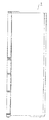
以下に本発明の実施形態を図面を参照して説明する。図1、図2は一実施形態の冷蔵庫を示す正面図及び右側面図である。冷蔵庫1は上部に冷蔵室2が配され、冷蔵室2の下方には温度切替室3及び製氷室4が左右に並設される。温度切替室3及び製氷室4の下方には冷凍室6が配され、冷凍室6の下方に野菜室5が配されている。   Embodiments of the present invention will be described below with reference to the drawings. 1 and 2 are a front view and a right side view showing a refrigerator according to one embodiment. The refrigerator 1 is provided with a refrigerator compartment 2 at the top, and below the refrigerator compartment 2, a temperature switching chamber 3 and an ice making chamber 4 are arranged side by side. A freezing room 6 is arranged below the temperature switching room 3 and the ice making room 4, and a vegetable room 5 is arranged below the freezing room 6.

冷蔵室2は貯蔵物を冷蔵保存し、野菜室5は冷蔵室2よりも高い室内温度(約8℃)で野菜を冷却保存する。温度切替室3は詳細を後述するように、使用者により室温を切り替えられるようになっている。冷凍室6は貯蔵物を冷凍保存し、製氷室4は冷凍室6に連通して氷を製氷する。   The refrigerator compartment 2 stores stored items in a refrigerator, and the vegetable compartment 5 cools and preserves vegetables at a room temperature (about 8 ° C.) higher than the refrigerator compartment 2. As will be described later in detail, the temperature switching chamber 3 can be switched by the user at room temperature. The freezer 6 stores the stored items in a frozen state, and the ice making chamber 4 communicates with the freezer 6 to make ice.

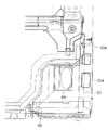
図3は冷蔵庫1の右側面断面図である。冷蔵庫1の本体部は外箱1aと内箱1bとの間に発泡断熱材1cが充填されている。製氷室4及び温度切替室3と冷蔵室2との間は断熱壁7により隔離され、冷凍室6と野菜室5との間は断熱壁8により隔離される。また、温度切替室3と冷凍室6との間は断熱壁35(図4参照)により隔離され、温度切替室3と製氷室4との間は縦断熱壁36(図4参照)により隔離されている。   FIG. 3 is a right side sectional view of the refrigerator 1. The main body of the refrigerator 1 is filled with a foam heat insulating material 1c between the outer box 1a and the inner box 1b. The ice making chamber 4 and the temperature switching chamber 3 are separated from the refrigerator compartment 2 by a heat insulating wall 7, and the freezer compartment 6 and the vegetable compartment 5 are separated from each other by a heat insulating wall 8. Further, the temperature switching chamber 3 and the freezing chamber 6 are separated by a heat insulating wall 35 (see FIG. 4), and the temperature switching chamber 3 and the ice making chamber 4 are separated by a vertical heat insulating wall 36 (see FIG. 4). ing.

発泡断熱材1cは外箱1aと内箱1bとの間に充填される際に断熱壁7、8内に同時に充填される。即ち、発泡断熱材1cの原液が外箱1aと内箱1bとの間とこれに連通する断熱壁7、8に同時に注入され、一体に発泡される。従来の断熱壁7、8は外箱1a、内箱1b間の発泡断熱材1cと異なる発泡スチロール等の断熱材が用いられていた。ウレタン発泡断熱材等の発泡断熱材1cを外箱1a、内箱1b間と同時に断熱壁7、8に充填することにより、断熱壁7、8を簡単に薄く形成することができる。従って、冷蔵室2の容積を広く確保することができる。   When the foam heat insulating material 1c is filled between the outer box 1a and the inner box 1b, the heat insulating walls 7 and 8 are filled simultaneously. That is, the stock solution of the foam heat insulating material 1c is injected simultaneously between the outer box 1a and the inner box 1b and into the heat insulating walls 7 and 8 communicating with the outer box 1a, and is foamed integrally. For the conventional heat insulating walls 7 and 8, a heat insulating material such as a polystyrene foam different from the foam heat insulating material 1c between the outer box 1a and the inner box 1b has been used. By filling the heat insulating walls 7 and 8 simultaneously with the space between the outer box 1a and the inner box 1b with the foam heat insulating material 1c such as urethane foam heat insulating material, the heat insulating walls 7 and 8 can be easily formed thin. Therefore, the volume of the refrigerator compartment 2 can be ensured widely.

また、断熱壁7、8の外装は内箱1bと別部材から成り、発泡断熱材1cの充填前は断熱壁7、8の側面が開口し、内箱1bは断熱壁7、8の側面に対向して開口する。発泡断熱材1cの充填により断熱壁7、8の側面の開口と内箱1bの開口とが連結して一体となる。これにより、断熱壁7、8によって隔離された温度帯の異なる各貯蔵室間での冷気や暖気の漏れが防止される。これにより、熱ロスの低減による省エネルギー化を図ることができる。また、断熱壁7、8の振動や、該振動による断熱壁7、8と内箱1bとの摺動によって発生する異常音を防止することができる。加えて、一体形成による構造的な強度の増加を図ることができる。   Moreover, the exterior of the heat insulating walls 7 and 8 is made of a separate member from the inner box 1b, and the side surfaces of the heat insulating walls 7 and 8 are opened before filling with the foam heat insulating material 1c. Open oppositely. By filling the foam heat insulating material 1c, the openings on the side surfaces of the heat insulating walls 7 and 8 and the opening of the inner box 1b are connected and integrated. Thereby, the leakage of cold air or warm air between the storage chambers separated by the heat insulating walls 7 and 8 in different temperature zones is prevented. Thereby, energy saving by reduction of heat loss can be achieved. Moreover, the abnormal noise which generate | occur | produces by the vibration of the heat insulation walls 7 and 8 and the sliding of the heat insulation walls 7 and 8 and the inner case 1b by this vibration can be prevented. In addition, the structural strength can be increased by integral formation.

製氷室4、冷凍室6、野菜室5及び温度切替室3には貯蔵物を収納する収納ケース43が設けられる。冷蔵室2には貯蔵物を載置する複数の収納棚41が設けられる。冷蔵室2の扉には複数の収納ポケット42が設けられる。これらにより、冷蔵庫1の使い勝手が向上されている。また、冷蔵室2内の下部には冷蔵室2と異なる温度帯の例えばチルド温度帯(約0℃)に維持された隔離室であるチルド室21が設けられている。チルド室21に替えて氷温(約−3℃)に維持される氷温室にしてもよい。   The ice making room 4, the freezing room 6, the vegetable room 5 and the temperature switching room 3 are provided with a storage case 43 for storing stored items. The refrigerator compartment 2 is provided with a plurality of storage shelves 41 on which stored items are placed. A plurality of storage pockets 42 are provided on the door of the refrigerator compartment 2. Thereby, the usability of the refrigerator 1 is improved. Further, a chilled chamber 21 which is an isolation chamber maintained in a chilled temperature range (about 0 ° C.), for example, in a temperature range different from that of the refrigerated chamber 2 is provided in the lower part of the refrigerator compartment 2. Instead of the chilled chamber 21, an ice greenhouse maintained at an ice temperature (about −3 ° C.) may be used.

野菜室5の背後には機械室50が設けられ、機械室50内に圧縮機57が配される。圧縮機57には凝縮器、膨張器(いずれも不図示)及び冷却器11が接続され、圧縮機57の駆動によりイソブタン等の冷媒が循環して冷凍サイクルが運転される。これにより、冷却器11が冷凍サイクルの低温側となる。   A machine room 50 is provided behind the vegetable room 5, and a compressor 57 is disposed in the machine room 50. The compressor 57 is connected to a condenser, an expander (not shown), and a cooler 11, and a refrigerant such as isobutane is circulated by driving the compressor 57 to operate a refrigeration cycle. Thereby, the cooler 11 becomes the low temperature side of the refrigeration cycle.

図6〜図8は機械室50内の側面図、背面図及び平面図を示している。機械室50の背面は金属から成る背面カバー50aにより覆われる。背面カバー50aには電装カバー52が取り付けられ、背面カバー50a及び電装カバー52により覆われた電装部51が設けられる。   6 to 8 show a side view, a rear view, and a plan view in the machine room 50. The back surface of the machine room 50 is covered with a back cover 50a made of metal. An electrical component cover 52 is attached to the back cover 50a, and an electrical component 51 covered with the back cover 50a and the electrical component cover 52 is provided.

電装部51には圧縮機57や各送風機等を制御する制御基板53を含む電装部品が内装される。電装部51を機械室50内に設置したので、冷蔵室2の背後に設置した場合に比して使用頻度の高い冷蔵室2の容積を広く確保し、冷蔵庫1の利便性を向上することができる。   The electrical component 51 includes electrical components including a control board 53 that controls the compressor 57 and each blower. Since the electrical unit 51 is installed in the machine room 50, it is possible to secure a large volume of the refrigerator room 2 that is frequently used as compared with the case where it is installed behind the refrigerator room 2, and to improve the convenience of the refrigerator 1. it can.

電装カバー52の側面には孔部52aが設けられる。孔部52aには樹脂成形品から成るリード線保持部54が嵌設される。リード線保持部54は電装部51内の電装部品に接続されるリード線(不図示)を中継する。   A hole 52 a is provided on a side surface of the electrical cover 52. A lead wire holding portion 54 made of a resin molded product is fitted into the hole 52a. The lead wire holding unit 54 relays a lead wire (not shown) connected to the electrical component in the electrical component unit 51.

背面カバー50aと電装ボックス52との間はシール部材58により密着される。シール部材58は、例えば、環状に繋がった状態のゴムや、独立発泡により形成されたスポンジ等から成る。リード線保持部54と孔部52aとの間はシール部材(不図示)によりシールされる。これにより、電装部51内を密閉して防水するとともに、可燃性冷媒が漏洩した際に電装部51内への可燃性冷媒の侵入による発火を防止することができる。   The back cover 50 a and the electrical box 52 are in close contact with each other by a seal member 58. The seal member 58 is made of, for example, a rubber in a ring-like state, a sponge formed by independent foaming, or the like. A space between the lead wire holding portion 54 and the hole 52a is sealed by a seal member (not shown). Thereby, while the inside of the electrical equipment part 51 is sealed and waterproofed, when the combustible refrigerant leaks, it is possible to prevent ignition due to the intrusion of the combustible refrigerant into the electrical equipment part 51.

電装カバー52は金属板の絞り加工により形成され、電装部品の発熱を容易に放熱することができる。また、制御基板53を支持する樹脂製の支持台55が電装カバー52に密着され、制御基板53の発熱を電装カバー52に伝えやすくなっている。   The electrical cover 52 is formed by drawing a metal plate and can easily dissipate heat generated by the electrical component. In addition, a resin support base 55 that supports the control board 53 is brought into close contact with the electrical cover 52 so that heat generated by the control board 53 can be easily transmitted to the electrical cover 52.

機械室50の前方の本体部の底面には凝縮器(不図示)が配され、凝縮器を冷却する凝縮器ファン60が機械室50の前面に設けられる。凝縮器ファン60の駆動により本体部の底面に設けた吸気口56から外気が取り込まれ、凝縮器と熱交換した空気は凝縮器ファン60を介して機械室50内に流入する。凝縮器ファン60は電装カバー52に向けて空気を送出し、電装カバー52と熱交換した後に圧縮機57を冷却する。そして、圧縮機57付近の背面カバー50aのコーナー側から外部に流出する。   A condenser (not shown) is disposed on the bottom surface of the main body portion in front of the machine room 50, and a condenser fan 60 that cools the condenser is provided on the front surface of the machine room 50. When the condenser fan 60 is driven, outside air is taken in from an intake port 56 provided on the bottom surface of the main body, and the air exchanged heat with the condenser flows into the machine chamber 50 via the condenser fan 60. The condenser fan 60 sends air toward the electrical cover 52 and heat-exchanges with the electrical cover 52, and then cools the compressor 57. And it flows out from the corner side of the back cover 50a near the compressor 57 to the outside.

凝縮器ファン60により電装カバー52に向けて空気を送出したので、電装部品の発熱をより効率的に放熱することができる。尚、前面側に枠部を有する樹脂成形品により電装カバー52を形成し、該枠部に金属プレートを嵌めてもよい。   Since air is sent toward the electrical cover 52 by the condenser fan 60, the heat generated by the electrical components can be radiated more efficiently. Alternatively, the electrical cover 52 may be formed of a resin molded product having a frame part on the front side, and a metal plate may be fitted to the frame part.

図3において、冷凍室6の背後には冷気通路31が設けられ、冷気通路31内には冷却器11が配される。冷蔵室2の背後には冷蔵室ダンパ20を介して冷気通路31と連通する冷気通路32が設けられる。冷凍サイクルの低温側となる冷却器11と冷気通路31を流通する空気とが熱交換して冷気が生成される。冷却器11の下方には冷却器11を除霜する除霜ヒータ33が設けられている。   In FIG. 3, a cold air passage 31 is provided behind the freezer compartment 6, and a cooler 11 is disposed in the cold air passage 31. Behind the refrigerator compartment 2 is provided a cold air passage 32 communicating with the cold air passage 31 via the refrigerator compartment damper 20. The cooler 11 on the low temperature side of the refrigeration cycle exchanges heat with the air flowing through the cold air passage 31 to generate cold air. A defrost heater 33 for defrosting the cooler 11 is provided below the cooler 11.

冷気通路31、32内には冷凍室送風機12及び冷蔵室送風機23がそれぞれ配される。詳細を後述するように、冷却器11で生成された冷気は冷凍室送風機12の駆動により冷気通路31の前部31aを流通し、冷凍室6、製氷室4及び温度切替室3に供給される。また、該冷気は冷蔵室送風機23の駆動により、冷気通路32を介して冷蔵室2、チルド室21及び野菜室5に供給される。   In the cold air passages 31 and 32, the freezer compartment fan 12 and the refrigerator compartment fan 23 are respectively arranged. As will be described in detail later, the cold air generated by the cooler 11 flows through the front portion 31 a of the cold air passage 31 by driving the freezer compartment fan 12, and is supplied to the freezer compartment 6, the ice making chamber 4, and the temperature switching chamber 3. . The cold air is supplied to the refrigerator compartment 2, the chilled compartment 21 and the vegetable compartment 5 through the cold passage 32 by driving the refrigerator compartment fan 23.

冷蔵室送風機23は軸流ファンから成り、軸方向を上下方向に向けて配置される。これにより、冷蔵室送風機23が高さ方向に低くなり、冷蔵室送風機23と断熱壁7とを正面投影において重なるように同一水平面内に配置することができる。従って、使用頻度の高い冷蔵室2の容積を広く確保することができる。また、低い圧力損失で冷気を冷気通路32に導くことができる。冷蔵室送風機23を遠心ファンにより形成してもよい。この時、遠心ファンの吸込み側を下方に向けて吐出口を左右方向に向けて配置し、吐出口から吐出する際または吐出した後に空気流が上方に向けられる。   The refrigerating room blower 23 is composed of an axial fan, and is arranged with the axial direction directed up and down. Thereby, the refrigerator compartment fan 23 becomes low in a height direction, and the refrigerator compartment fan 23 and the heat insulation wall 7 can be arrange | positioned in the same horizontal surface so that it may overlap in a front projection. Therefore, the volume of the refrigerator compartment 2 with high use frequency can be secured widely. Further, the cold air can be guided to the cold air passage 32 with a low pressure loss. The refrigerator compartment fan 23 may be formed by a centrifugal fan. At this time, the suction port of the centrifugal fan is directed downward and the discharge port is disposed in the left-right direction, and the air flow is directed upward when discharging from the discharge port or after discharging.

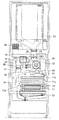
図4は冷蔵庫1の正面断面図を示している。冷凍室6の背後の冷気通路31は冷凍室送風機12の前面を開口し、冷凍室送風機12によって製氷室4及び冷凍室6に空気が送出される。製氷室4に連通する冷凍室6の下部には冷凍室戻り口22が設けられる。また、冷気通路31から分岐して温度切替室3に冷気を導く導入通風路15が設けられる。   FIG. 4 shows a front sectional view of the refrigerator 1. The cold air passage 31 behind the freezer compartment 6 opens the front surface of the freezer compartment fan 12, and air is sent out to the ice making room 4 and the freezer compartment 6 by the freezer compartment fan 12. A freezer compartment return port 22 is provided at the lower part of the freezer compartment 6 communicating with the ice making chamber 4. Further, an introduction ventilation path 15 that branches from the cold air passage 31 and guides the cold air to the temperature switching chamber 3 is provided.

冷気通路31の上部は冷蔵室ダンパ20を介して冷気通路32に連通する。冷蔵室ダンパ20を開いて冷凍室送風機12を駆動すると冷蔵室2及びチルド室21に冷気が供給される。冷蔵室ダンパ20は正面投影において縦断熱壁36と重なるように縦断熱壁36の後方に配される。   The upper part of the cold air passage 31 communicates with the cold air passage 32 via the refrigerator compartment damper 20. When the refrigerator compartment damper 20 is opened and the freezer compartment fan 12 is driven, cold air is supplied to the refrigerator compartment 2 and the chilled compartment 21. The refrigerator compartment damper 20 is arranged behind the vertical heat insulation wall 36 so as to overlap the vertical heat insulation wall 36 in front projection.

温度切替室3の容積を広く確保するため、温度切替室3と製氷室4とを隔離する縦断熱壁36は図中、右側に偏って配置される。冷気通路32は冷蔵室ダンパ20の出口側から左右に分岐して冷蔵室2全体から冷気が吐出されるようになっている。この時、冷蔵室ダンパ20を左右方向の中央に配置すると、左右に分岐する冷気通路32に均一に冷気を流通させることができる。   In order to secure a large volume of the temperature switching chamber 3, the vertical heat insulating wall 36 that separates the temperature switching chamber 3 and the ice making chamber 4 is arranged to be biased to the right side in the drawing. The cold air passage 32 branches from the outlet side of the cold room damper 20 to the left and right so that the cold air is discharged from the entire cold room 2. At this time, if the refrigerator compartment damper 20 is arranged in the center in the left-right direction, the cold air can be evenly circulated through the cold air passage 32 branched to the left and right.

しかし、温度切替室3の背後に冷気通路31の前部31aや冷蔵室ダンパ20のバッフルを設けると、温度切替室3から冷気通路31内の冷気に熱が放出される。冷気通路31を流通する冷気が例えば−23℃に生成され、温度切替室3が該冷気よりも高温(例えば、3℃や8℃や50℃)に制御されていると、熱ロスが大きくなる。このため、縦断熱壁36の後方に冷蔵室ダンパ20のバッフルや冷気通路31の前部31a(図3参照)を設け、温度切替室3から冷気への熱の放出が防止されている。従って、冷蔵室ダンパ20を左右方向の中央に近づけるとともに、冷却効率をより向上することができる。   However, if the front part 31 a of the cold air passage 31 and the baffle of the refrigerator compartment damper 20 are provided behind the temperature switching chamber 3, heat is released from the temperature switching chamber 3 to the cold air in the cold air passage 31. If cold air flowing through the cold air passage 31 is generated at, for example, -23 ° C and the temperature switching chamber 3 is controlled to a temperature higher than the cold air (for example, 3 ° C, 8 ° C, or 50 ° C), heat loss increases. . For this reason, the baffle of the refrigerator compartment damper 20 and the front part 31a (see FIG. 3) of the cold air passage 31 are provided behind the vertical heat insulation wall 36, and release of heat from the temperature switching chamber 3 to the cold air is prevented. Accordingly, the refrigerator compartment damper 20 can be brought closer to the center in the left-right direction, and the cooling efficiency can be further improved.

冷蔵室2の背面下部には冷蔵室流出口2aが開口し、野菜室5には野菜室流入口(不図示)が設けられる。冷蔵室流出口2aと野菜室流入口とは温度切替室3の背面を通る連結路34により連結され、冷蔵室2と野菜室5が連通している。野菜室5の背面上部には冷気通路31に連通する戻り通風路46(図3参照)が設けられている。   A refrigerator compartment outlet 2 a is opened at the lower back of the refrigerator compartment 2, and a vegetable compartment inlet (not shown) is provided in the vegetable compartment 5. The refrigerator compartment outlet 2 a and the vegetable compartment inlet are connected by a connection path 34 that passes through the back surface of the temperature switching chamber 3, and the refrigerator compartment 2 and the vegetable compartment 5 communicate with each other. A return ventilation path 46 (see FIG. 3) communicating with the cold air passage 31 is provided at the upper back of the vegetable compartment 5.

温度切替室3の上部には温度切替室送風機18及びヒータ16が配置される。温度切替室3の右下部には温度切替室吐出ダンパ37が設けられる。温度切替室吐出ダンパ37は導入通風路15上に配され、温度切替室送風機18は導入通風路15の上部に配置される。温度切替室吐出ダンパ37を開いて温度切替室送風機18を駆動すると導入通風路15を介して冷却器11から冷気が温度切替室3に流入する。温度切替室吐出ダンパ37の開閉量によって導入通風路15から温度切替室3に流入する風量が調整される。   A temperature switching chamber blower 18 and a heater 16 are disposed on the upper portion of the temperature switching chamber 3. A temperature switching chamber discharge damper 37 is provided at the lower right of the temperature switching chamber 3. The temperature switching chamber discharge damper 37 is disposed on the introduction ventilation path 15, and the temperature switching chamber blower 18 is disposed on the introduction ventilation path 15. When the temperature switching chamber discharge damper 37 is opened and the temperature switching chamber blower 18 is driven, cold air flows from the cooler 11 into the temperature switching chamber 3 through the introduction ventilation path 15. The amount of air flowing into the temperature switching chamber 3 from the introduction ventilation path 15 is adjusted by the opening / closing amount of the temperature switching chamber discharge damper 37.

温度切替室3の左下部には温度切替室戻りダンパ38が設けられる。温度切替室戻りダンパ38は下方に延びる戻り通風路17を開閉し、温度切替室3内の空気は戻り通風路17を介して冷気通路31に戻るようになっている。   A temperature switching chamber return damper 38 is provided at the lower left portion of the temperature switching chamber 3. The temperature switching chamber return damper 38 opens and closes the return ventilation path 17 extending downward, and the air in the temperature switching chamber 3 returns to the cool air passage 31 via the return ventilation path 17.

冷却器11は冷媒が流通する冷媒管11aが蛇行して形成され、冷媒管11aの左右端部がエンドプレート11bにより支持されている。冷媒管11aには放熱用の多数のフィン(不図示)が接して設けられている。   The cooler 11 is formed by meandering refrigerant pipes 11a through which refrigerant flows, and left and right ends of the refrigerant pipes 11a are supported by end plates 11b. A large number of fins (not shown) for heat dissipation are provided in contact with the refrigerant pipe 11a.

戻り通風路17を流通する空気は冷却器11の上下方向の中間に設けた流出口17aから冷却器11に戻される。また、冷凍室戻り口22を介して冷凍室6から流出する冷気は冷却器11の下部に戻り、野菜室5から流出して戻り通路46を通る冷気は冷却器11の下方に戻る。従って、各貯蔵室から流出した冷気は冷却器11に分散して戻される。このため、各貯蔵室を循環して戻ってきた水分を含む冷気による霜が一部に集中的に発生せずに、冷却器11全体に分散して発生する。これにより、霜による冷気流れの目詰まりが防止され、冷却器11の冷却性能低下を防止することができる。   The air flowing through the return air passage 17 is returned to the cooler 11 from an outlet 17 a provided in the middle of the cooler 11 in the vertical direction. The cold air flowing out from the freezer compartment 6 through the freezer return port 22 returns to the lower part of the cooler 11, and the cold air flowing out from the vegetable compartment 5 and passing through the return passage 46 returns to the lower part of the cooler 11. Therefore, the cold air flowing out from each storage chamber is returned to the cooler 11 in a dispersed manner. For this reason, the frost by the cold air containing the water | moisture content which circulated through each store room and returned does not generate | occur | produce intensively, but disperse | distributes and generate | occur | produces in the whole cooler 11. Thereby, clogging of the cold air flow due to frost is prevented, and a decrease in cooling performance of the cooler 11 can be prevented.

また、容積の狭い温度切替室3を流通した冷気が冷却器11の上部で冷却され、容積の広い冷蔵室3、野菜室5及び冷凍室6を流通した冷気が冷却器11の上下方向の全体で冷却される。従って、温度切替室3から流出した冷気が必要以上に冷却器11と熱交換されず、冷却器11の熱交換効率を向上することができる。   In addition, the cold air that has flowed through the temperature switching chamber 3 with a small volume is cooled at the upper part of the cooler 11, and the cold air that has flowed through the large-sized refrigerating chamber 3, the vegetable room 5, and the freezer room 6 Cooled by. Therefore, the cold air flowing out from the temperature switching chamber 3 is not heat exchanged with the cooler 11 more than necessary, and the heat exchange efficiency of the cooler 11 can be improved.

また、冷凍室戻り口22を介して冷凍室6から流出した冷気は両側のエンドプレート11bの間に導かれる。野菜室5から流出した冷気は戻り通風路46(図3参照)を介して冷却器11の両側のエンドプレート11bの内側及び外側の左右方向全体に導かれる。   Further, the cold air flowing out from the freezer compartment 6 through the freezer return port 22 is guided between the end plates 11b on both sides. The cold air flowing out from the vegetable compartment 5 is guided to the entire left and right direction inside and outside the end plates 11b on both sides of the cooler 11 via a return ventilation path 46 (see FIG. 3).

これにより、野菜室5から流出した冷気の熱交換面積が冷凍室6から流出した冷気の熱交換面積よりも大きくなる。従って、冷凍室6から戻る低温の冷気を必要以上に冷却させず、野菜室5から戻る高温の冷気を冷却器11全体で冷却して冷却器11の熱交換効率をより向上することができる。   Thereby, the heat exchange area of the cold air flowing out from the vegetable compartment 5 becomes larger than the heat exchange area of the cold air flowing out from the freezer compartment 6. Therefore, the low temperature cold air returning from the freezer compartment 6 is not cooled more than necessary, and the high temperature cold air returning from the vegetable compartment 5 is cooled by the entire cooler 11 so that the heat exchange efficiency of the cooler 11 can be further improved.

温度切替室3は冷凍温度に維持される場合があるため、エンドプレート11bには戻り通風路17の流出口17aに対向する位置に切欠き(不図示)が設けられる。これにより、温度切替室3を流出した冷気を両側のエンドプレート11bの間に導くことができる。   Since the temperature switching chamber 3 may be maintained at the freezing temperature, the end plate 11b is provided with a notch (not shown) at a position facing the outlet 17a of the return ventilation path 17. Thereby, the cold air that has flowed out of the temperature switching chamber 3 can be guided between the end plates 11b on both sides.

冷媒管11aの上部にはアキュームレータ45が接続される。アキュームレータ45は温度切替室3から離れて製氷室4側の端部に配置される。これにより、温度切替室吐出ダンパ37を温度切替室3の下部に配置してもアキュームレータ45と干渉しない。その結果、冷蔵室ダンパ20と温度切替室吐出ダンパ37との干渉を回避して縦断熱壁36の後方に冷蔵室ダンパ20を配置することができる。   An accumulator 45 is connected to the upper part of the refrigerant pipe 11a. The accumulator 45 is disposed at the end of the ice making chamber 4 away from the temperature switching chamber 3. Thereby, even if the temperature switching chamber discharge damper 37 is disposed below the temperature switching chamber 3, it does not interfere with the accumulator 45. As a result, it is possible to avoid the interference between the refrigerator compartment damper 20 and the temperature switching chamber discharge damper 37 and arrange the refrigerator compartment damper 20 behind the vertical heat insulating wall 36.

図5は温度切替室3の側面断面図を示している。温度切替室3の上下面は断熱壁7、35により冷蔵室2及び冷凍室6と断熱隔離されている。また、温度切替室3の前面は回動式の扉9により開閉可能になっている。温度切替室3の背面は背面板40により覆われている。背面板40の上部には温度切替室3に空気が流入する空気流入口40aが設けられる。背面板40の下部には温度切替室3から空気が流出する空気流出口40bが設けられる。   FIG. 5 shows a side sectional view of the temperature switching chamber 3. The upper and lower surfaces of the temperature switching chamber 3 are insulated from the refrigerator compartment 2 and the freezer compartment 6 by heat insulation walls 7 and 35. The front surface of the temperature switching chamber 3 can be opened and closed by a pivotable door 9. The back surface of the temperature switching chamber 3 is covered with a back plate 40. An air inlet 40 a through which air flows into the temperature switching chamber 3 is provided at the upper part of the back plate 40. An air outlet 40 b through which air flows out from the temperature switching chamber 3 is provided at the lower part of the back plate 40.

温度切替室送風機18は空気流入口40aに面して設けられ、温度切替室送風機18と空気流入口40aとの間にヒータ16が配置される。ヒータ16は熱輻射式のガラス管ヒータから成り、背面板40を介して放出される輻射熱により温度切替室3を昇温する。温度切替室送風機18はヒータ16の表面に向けて送風するように配置されている。これにより、ヒータ16の表面温度を下げて安全性を向上することができる。ヒータ16の上方にはヒータ16による異常加熱を検知する温度センサ24が設けられている。また、空気流出口40bには温度切替室3内の温度を検知する温度センサ(不図示)が設けられている。   The temperature switching chamber blower 18 is provided facing the air inlet 40a, and the heater 16 is disposed between the temperature switching chamber blower 18 and the air inlet 40a. The heater 16 is formed of a heat radiation type glass tube heater, and raises the temperature of the temperature switching chamber 3 by radiant heat released through the back plate 40. The temperature switching chamber blower 18 is disposed so as to blow toward the surface of the heater 16. Thereby, the surface temperature of the heater 16 can be lowered and safety can be improved. A temperature sensor 24 that detects abnormal heating by the heater 16 is provided above the heater 16. The air outlet 40b is provided with a temperature sensor (not shown) for detecting the temperature in the temperature switching chamber 3.

温度切替室3の下部には表面全体から一様に放熱するパネルヒータ44が設けられる。パネルヒータ44は断熱壁35との間に隙間dを介して配置され、上下面から一様に放熱して温度切替室3内を昇温する。両面から放熱することにより加熱効率を向上することができる。隙間dは10〜20mmにすると望ましい。これにより、温度切替室3内の容積を確保するとともに、断熱壁35の表面温度の上昇を抑制して冷凍室6への熱漏洩を防止することができる。   A panel heater 44 that uniformly dissipates heat from the entire surface is provided below the temperature switching chamber 3. The panel heater 44 is disposed between the heat insulating wall 35 via a gap d, and uniformly heats from the upper and lower surfaces to raise the temperature in the temperature switching chamber 3. Heat dissipation can be improved by dissipating heat from both sides. The gap d is preferably 10 to 20 mm. Thereby, while ensuring the volume in the temperature switching chamber 3, the raise of the surface temperature of the heat insulation wall 35 can be suppressed, and the heat leak to the freezer compartment 6 can be prevented.

温度切替室3内の収納ケース43は金属から成り、パネルヒータ44上に載置される。これにより、収納ケース43内の貯蔵物を効率よく加熱することができる。また、パネルヒータ44を後端で枢支してもよい。これにより、パネルヒータ44の前部を持ち上げてパネルヒータ44の下方を容易に清掃することができる。   The storage case 43 in the temperature switching chamber 3 is made of metal and placed on the panel heater 44. Thereby, the stored item in the storage case 43 can be efficiently heated. The panel heater 44 may be pivotally supported at the rear end. Thereby, the front part of the panel heater 44 can be lifted and the lower part of the panel heater 44 can be easily cleaned.

空気流出口40bの後方には温度切替室戻りダンパ38が配される。温度切替室戻りダンパ38は下方に開口する開口部38aと後方に開口する開口部38bとが形成され、回動により一方を開いて他方を閉じるバッフル38cを有している。開口部38aは下方に延びる戻り通風路17に臨み、開口部38bと温度切替室送風機18の吸気側とは連通路30により連通する。   A temperature switching chamber return damper 38 is disposed behind the air outlet 40b. The temperature switching chamber return damper 38 has an opening 38a that opens downward and an opening 38b that opens backward, and has a baffle 38c that opens one and closes the other by rotation. The opening 38 a faces the return ventilation path 17 extending downward, and the opening 38 b communicates with the intake side of the temperature switching chamber blower 18 through the communication path 30.

温度切替室戻りダンパ38の開口部38bを開くと空気流出口40bから流出する空気は温度切替室送風機18の吸気側に導かれるとともに、戻り通風路17が閉じられる。従って、開口部38a及び温度切替室吐出ダンパ37(図4参照)を閉じると、温度切替室送風機18の駆動により温度切替室3の空気を循環させることができる。尚、以下の説明において、開口部38aを開いてて開口部38bを閉じた場合を温度切替室戻りダンパ38が開いた状態といい、開口部38aを閉じて開口部38bを開いた場合を温度切替室戻りダンパ38が閉じた状態という。   When the opening 38b of the temperature switching chamber return damper 38 is opened, the air flowing out from the air outlet 40b is guided to the intake side of the temperature switching chamber blower 18, and the return ventilation path 17 is closed. Therefore, when the opening 38 a and the temperature switching chamber discharge damper 37 (see FIG. 4) are closed, the air in the temperature switching chamber 3 can be circulated by driving the temperature switching chamber blower 18. In the following description, the case where the opening 38a is opened and the opening 38b is closed is referred to as a state where the temperature switching chamber return damper 38 is opened, and the case where the opening 38a is closed and the opening 38b is opened. The switching chamber return damper 38 is in a closed state.

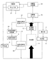
図9は冷蔵庫1の冷気の流れを示す冷気回路図である。冷凍室6、冷蔵室2及び温度切替室3はそれぞれ並列に配される。製氷室4は冷凍室6と直列に配され、野菜室5は冷蔵室2と直列に配される。冷却器11で生成された冷気は、冷凍室送風機12の駆動により製氷室4及び冷凍室6に送出される。製氷室4に送出された冷気は製氷室4及び冷凍室6を流通し、冷凍室戻り口22から流出して冷却器11に戻る。これにより、製氷室4及び冷凍室6内が冷却される。   FIG. 9 is a cold air circuit diagram showing the flow of cold air in the refrigerator 1. The freezer compartment 6, the refrigerator compartment 2, and the temperature switching chamber 3 are each arranged in parallel. The ice making room 4 is arranged in series with the freezer room 6, and the vegetable room 5 is arranged in series with the refrigerator room 2. The cold air generated by the cooler 11 is sent to the ice making room 4 and the freezing room 6 by driving the freezing room blower 12. The cold air sent to the ice making room 4 flows through the ice making room 4 and the freezing room 6, flows out from the freezing room return port 22, and returns to the cooler 11. As a result, the ice making chamber 4 and the freezing chamber 6 are cooled.

冷凍室送風機12の排気側で分岐した冷気は冷蔵室送風機23の駆動により、冷蔵室ダンパ20を介して冷蔵室2及びチルド室21に送出される。冷蔵室2及びチルド室21を流通して貯蔵物と熱交換した冷気は連結路34を介して野菜室5に流入する。野菜室5に流入した冷気は野菜室5内を流通し、戻り通風路46を介して冷却器11に戻る。これにより、冷蔵室2及び野菜室5内が冷却され、設定温度になると冷蔵室ダンパ20が閉じられる。   The cold air branched on the exhaust side of the freezer compartment fan 12 is sent to the refrigerating compartment 2 and the chilled compartment 21 through the refrigerating compartment damper 20 by driving the refrigerating compartment blower 23. The cold air that has flowed through the refrigerator compartment 2 and the chilled compartment 21 and exchanged heat with the stored material flows into the vegetable compartment 5 through the connection path 34. The cold air flowing into the vegetable compartment 5 circulates in the vegetable compartment 5 and returns to the cooler 11 through the return ventilation path 46. Thereby, the inside of the refrigerator compartment 2 and the vegetable compartment 5 is cooled, and when it becomes preset temperature, the refrigerator compartment damper 20 will be closed.

また、冷凍室送風機12の排気側で分岐した冷気は、温度切替室送風機18の駆動により温度切替室吐出ダンパ37を介して温度切替室3に流入する。温度切替室3に流入した冷気は温度切替室3内を流通して温度切替室戻りダンパ38から流出し、戻り通風路17を介して冷却器11に戻る。これにより、温度切替室3内が冷却される。   Further, the cold air branched on the exhaust side of the freezer compartment fan 12 flows into the temperature switching chamber 3 through the temperature switching chamber discharge damper 37 by driving the temperature switching chamber blower 18. The cold air that has flowed into the temperature switching chamber 3 flows through the temperature switching chamber 3, flows out of the temperature switching chamber return damper 38, and returns to the cooler 11 through the return ventilation path 17. Thereby, the inside of the temperature switching chamber 3 is cooled.

前述のように、温度切替室3は使用者の操作により室内温度を切り替えることができるようになっている。温度切替室3の動作モードは温度帯に応じてワイン(8℃)、冷蔵(3℃)、チルド(0℃)、ソフト冷凍(−8℃)、冷凍(−15℃)の各冷却モードが設けられる。   As described above, the temperature switching chamber 3 can switch the room temperature by a user's operation. The operation modes of the temperature switching chamber 3 are wine (8 ° C.), refrigeration (3 ° C.), chilled (0 ° C.), soft freezing (−8 ° C.), and freezing (−15 ° C.) depending on the temperature zone. Provided.

これにより、使用者は所望の温度で貯蔵物を冷凍または冷蔵して冷却保存できる。室内温度の切り替えは温度切替室吐出ダンパ37を開く量を可変して行うことができる。尚、例えば冷凍の室内温度から冷蔵の室内温度に切り替える際にヒータ16またはパネルヒータ44に通電して昇温してもよい。これにより、迅速に所望の室内温度に切り替えることができる。   Thus, the user can store the refrigerated product at a desired temperature by refrigeration or refrigeration. The room temperature can be switched by varying the amount of opening of the temperature switching chamber discharge damper 37. For example, the heater 16 or the panel heater 44 may be energized to switch the temperature from the frozen room temperature to the refrigerated room temperature. Thereby, it can switch to desired room temperature rapidly.

また、ヒータ16及びパネルヒータ44に通電することにより、温度切替室3の室内温度を貯蔵物を冷却保存する低温側から常温よりも高温の高温側に切り替えることができる。これにより、調理済み加熱食品の一時的な保温や温調理等を行うことができる。   Further, by energizing the heater 16 and the panel heater 44, the room temperature of the temperature switching chamber 3 can be switched from the low temperature side where the stored items are cooled and stored to the high temperature side higher than the normal temperature. Thereby, temporary heat insulation, warm cooking, etc. of the cooked heated food can be performed.

温度切替室3を高温側に切り替えると、温度切替室戻りダンパ38の開口部38a及び温度切替室吐出ダンパ37が閉じられる。そして、温度切替室送風機18及びヒータ16が駆動され、温度切替室3内を昇温する昇温期間に移行する。   When the temperature switching chamber 3 is switched to the high temperature side, the opening 38a of the temperature switching chamber return damper 38 and the temperature switching chamber discharge damper 37 are closed. Then, the temperature switching chamber blower 18 and the heater 16 are driven to shift to a temperature raising period in which the temperature in the temperature switching chamber 3 is raised.

温度切替室3が所定の温度まで昇温されると温度切替室送風機18及びヒータ16が停止され、パネルヒータ44が駆動される。これにより、温度切替室3を所定温度に維持して貯蔵物を保温する保温期間に移行する。保温期間では設定温度付近でパネルヒータ44をオンオフして設定温度が維持される。   When the temperature switching chamber 3 is heated to a predetermined temperature, the temperature switching chamber blower 18 and the heater 16 are stopped, and the panel heater 44 is driven. Thereby, it transfers to the heat retention period which maintains the temperature switching chamber 3 at predetermined temperature, and heats a stored thing. During the heat retention period, the panel heater 44 is turned on and off in the vicinity of the set temperature to maintain the set temperature.

昇温期間に容量の大きいヒータ16及びパネルヒータ44を駆動することにより、所望の室内温度まで迅速に昇温することができる。また、保温期間に温度切替室送風機18及びヒータ16を停止して容量の小さいパネルヒータ44を駆動するので、省電力化を図るとともに容易に室内を均一な温度に維持することができる。また、また、温度切替室送風機18が停止されるため貯蔵物に直接温風が当らなくなり、貯蔵物の乾燥を防止または低減することができる。   By driving the heater 16 and the panel heater 44 having a large capacity during the temperature raising period, the temperature can be quickly raised to a desired room temperature. Further, since the temperature switching chamber blower 18 and the heater 16 are stopped and the panel heater 44 having a small capacity is driven during the heat retention period, the power can be saved and the room can be easily maintained at a uniform temperature. Moreover, since the temperature switching chamber blower 18 is stopped, the hot air is not directly applied to the stored item, and drying of the stored item can be prevented or reduced.

高温側の室内温度は、主な食中毒菌の発育温度が30℃〜45℃であるため、ヒータ容量の公差や温度切替室3内の温度分布等を考慮して50℃以上にするとよい。これにより、食中毒菌の繁殖を防止できる。   Since the growth temperature of the main food poisoning bacteria is 30 ° C. to 45 ° C., the indoor temperature on the high temperature side is preferably set to 50 ° C. or more in consideration of the tolerance of the heater capacity, the temperature distribution in the temperature switching chamber 3, and the like. Thereby, propagation of food poisoning bacteria can be prevented.

また、冷蔵庫に用いられる一般的な樹脂製部品の耐熱温度が80℃であるため、高温側の室内温度を80℃以下にすると安価に実現することができる。加えて、食中毒菌を滅菌するためには、例えば腸管出血性大腸菌(病原性大腸菌O157)の場合では75℃で1分間の加熱が必要である。従って、高温側の室内温度を75℃〜80℃にするとより望ましい。   Moreover, since the heat-resistant temperature of the general resin parts used for a refrigerator is 80 degreeC, when the room temperature of a high temperature side shall be 80 degrees C or less, it can implement | achieve cheaply. In addition, in order to sterilize food poisoning bacteria, for example, in the case of enterohemorrhagic E. coli (pathogenic E. coli O157), heating at 75 ° C. for 1 minute is required. Therefore, it is more desirable to set the indoor temperature on the high temperature side to 75 ° C to 80 ° C.

以下は55℃での食中毒菌の減菌に関する試験結果である。試験サンプルは初期状態で大腸菌2.4×10³CFU/mL、黄色ブドウ球菌2.0×103CFU/mL、サルモネラ2.1×103CFU/mL、腸炎ビブリオ1.5×103CFU/mL、セレウス4.0×103CFU/mLを含んでいる。この試験サンプルを40分間で3℃から55℃に加温し、55℃で3.5時間保温後、80分間で55℃から3℃に戻して再度各菌の量を調べた。その結果、いずれの菌も10CFU/mL以下(検出せず)のレベルまで減少していた。従って、温度切替室3の高温側の設定温度を55℃としても充分減菌効果がある。 The following are the test results on the sterilization of food poisoning bacteria at 55 ° C. In the initial state, E. coli 2.4 × 10 3 CFU / mL, Staphylococcus aureus 2.0 × 10 3 CFU / mL, Salmonella 2.1 × 10 3 CFU / mL, Vibrio parahaemolyticus 1.5 × 10 3 CFU / ML, Cereus 4.0 × 10 3 CFU / mL. This test sample was heated from 3 ° C. to 55 ° C. over 40 minutes, kept at 55 ° C. for 3.5 hours, then returned from 55 ° C. to 3 ° C. over 80 minutes, and the amount of each bacterium was examined again. As a result, all the bacteria were reduced to a level of 10 CFU / mL or less (not detected). Therefore, even if the set temperature on the high temperature side of the temperature switching chamber 3 is 55 ° C., there is a sufficient sterilization effect.

本実施形態によると、上方から冷蔵室2、温度切替室3、冷凍室6、野菜室5の順に配置したので、冷凍室6及び野菜室5の横幅が広くなり、冷蔵庫1の利便性が向上する。また、温度切替室3と冷凍室6とが隣接するため、冷凍室6に近設される冷却器11から温度切替室3までの冷気経路が短くなる。このため、冷凍温度に維持される温度切替室3に供給される冷気の昇温を防止し、冷却効率を向上することができる。   According to the present embodiment, since the refrigerator compartment 2, the temperature switching chamber 3, the freezer compartment 6, and the vegetable compartment 5 are arranged in this order from the top, the width of the freezer compartment 6 and the vegetable compartment 5 is widened, and the convenience of the refrigerator 1 is improved. To do. In addition, since the temperature switching chamber 3 and the freezer compartment 6 are adjacent to each other, the cool air path from the cooler 11 provided close to the freezer compartment 6 to the temperature switching chamber 3 is shortened. For this reason, the temperature rise of the cold air supplied to the temperature switching chamber 3 maintained at the freezing temperature can be prevented, and the cooling efficiency can be improved.

また、使用頻度の高い冷蔵室2を最上段に配置することにより冷蔵庫1の利便性が向上する。加えて、冷蔵室2の下方に野菜室5が配置されるため冷蔵室2内の冷気を自重により容易に野菜室5に導くことができ、送風効率低下を防止することができる。更に、温度切替室3を冷凍室6及び野菜室3の上方に配置しているため、使用者が立ったままで重く高温の鍋等を容易に出し入れすることができる。従って、冷蔵庫1の利便性をより向上できるとともに、鍋等をひっくり返す危険が減少して安全性を向上することができる。   Moreover, the convenience of the refrigerator 1 improves by arrange | positioning the refrigerator compartment 2 with a high usage frequency in the uppermost stage. In addition, since the vegetable compartment 5 is disposed below the refrigerator compartment 2, the cold air in the refrigerator compartment 2 can be easily guided to the vegetable compartment 5 by its own weight, and a reduction in blowing efficiency can be prevented. Furthermore, since the temperature switching chamber 3 is disposed above the freezer compartment 6 and the vegetable compartment 3, it is possible to easily put in and out a heavy and hot pan or the like while the user is standing. Therefore, the convenience of the refrigerator 1 can be further improved, and the risk of turning over the pan or the like can be reduced, thereby improving safety.

また、温度切替室3と製氷室4とを仕切る縦断熱壁36と冷蔵室ダンパ20とが正面投影において重なるように配置したので、製氷室4及び温度切替室3の奥行方向を広く取ることができる。従って、製氷室4の横幅を狭くしても必要な容積を確保することができるとともに温度切替室3を広く確保することができ、冷蔵庫1の利便性が向上する。   Further, since the vertical heat insulating wall 36 that separates the temperature switching chamber 3 and the ice making chamber 4 and the refrigerator compartment damper 20 are arranged so as to overlap in front projection, the depth direction of the ice making chamber 4 and the temperature switching chamber 3 can be widened. it can. Therefore, even if the lateral width of the ice making chamber 4 is narrowed, the necessary volume can be secured and the temperature switching chamber 3 can be secured widely, and the convenience of the refrigerator 1 is improved.

また、温度切替室3を常温よりも高温に可変できるので、厚く形成される縦断熱壁36の背後のデッドスペースを削減して容積効率を向上することができる。   Further, since the temperature switching chamber 3 can be changed to a temperature higher than room temperature, the dead space behind the thick vertical heat insulating wall 36 can be reduced and the volumetric efficiency can be improved.

また、冷蔵室送風機23の軸方向を鉛直方向に向け、冷蔵室2の周囲を囲む水平な断熱壁7と正面投影において重なる位置に冷蔵室送風機23を配置したので、使用頻度の高い冷蔵室1の内容積を広く確保することができる。従って、冷蔵庫1の利便性がより向上する。尚、冷凍室6(冷凍室6に連通する製氷室4を含む)と冷蔵室2との間に他の貯蔵室が設けられる場合は、冷蔵室送風機23を冷凍室6の周囲を囲む水平な断熱壁と正面投影において重なる位置に配置してもよい。   In addition, since the refrigerator compartment fan 23 is arranged at a position where the axial direction of the refrigerator compartment fan 23 is oriented in the vertical direction and overlaps with the horizontal heat insulation wall 7 surrounding the refrigerator compartment 2 in front projection, the refrigerator compartment 1 having a high use frequency is used. A large internal volume can be secured. Therefore, the convenience of the refrigerator 1 is further improved. In the case where another storage room is provided between the freezer compartment 6 (including the ice making room 4 communicating with the freezer compartment 6) and the refrigerator compartment 2, the refrigerator compartment fan 23 is placed horizontally around the freezer compartment 6. You may arrange | position in the position which overlaps in a heat insulation wall and front projection.

また、製氷室4の容積よりも温度切替室3の容積を広くしたので、通常必要な氷の貯蔵量を確保するとともに、より多くの貯蔵物を保温または冷却保存することができる。従って、冷蔵庫1の利便性をより向上することができる。   Further, since the volume of the temperature switching chamber 3 is made larger than the volume of the ice making chamber 4, it is possible to ensure a necessary amount of ice storage and to keep more stored items warm or cold. Therefore, the convenience of the refrigerator 1 can be further improved.

尚、本実施形態において、野菜室5の流出口にダンパを設けてもよい。これにより、温度切替室3を高温側から低温側に切り替えた際に、該ダンパを閉じて温度切替室3からの熱風が野菜室5に逆流することを防止できる。また、温度切替室3を高温側から低温側へ切り替える際に冷凍室送風機12が停止されている場合には、冷凍室戻り口22が閉じられるように通路開閉機構(例えば、ダンパ)を設けてもよい。これにより、温度切替室送風機18の駆動によって冷凍室戻り口22から冷凍室6内へ熱風が逆流することを防止できる。   In the present embodiment, a damper may be provided at the outlet of the vegetable compartment 5. Thereby, when the temperature switching chamber 3 is switched from the high temperature side to the low temperature side, it is possible to prevent the hot air from the temperature switching chamber 3 from flowing backward into the vegetable chamber 5 by closing the damper. In addition, when the freezer compartment fan 12 is stopped when the temperature switching chamber 3 is switched from the high temperature side to the low temperature side, a passage opening / closing mechanism (for example, a damper) is provided so that the freezer compartment return port 22 is closed. Also good. Thereby, it is possible to prevent the hot air from flowing backward from the freezer return port 22 into the freezer compartment 6 by driving the temperature switching chamber blower 18.

本発明によると、温度切替室を有した冷蔵庫に利用することができる。   According to the present invention, it can be used for a refrigerator having a temperature switching chamber.

本発明の実施形態の冷蔵庫を示す正面図The front view which shows the refrigerator of embodiment of this invention 本発明の実施形態の冷蔵庫を示す右側面図The right view which shows the refrigerator of embodiment of this invention 本発明の実施形態の冷蔵庫を示す右側面断面図Sectional drawing of right side which shows the refrigerator of embodiment of this invention 本発明の実施形態の冷蔵庫を示す正面断面図Front sectional drawing which shows the refrigerator of embodiment of this invention 本発明の実施形態の冷蔵庫の温度切替室を示す右側面断面図Cross section of the right side showing the temperature switching chamber of the refrigerator of the embodiment of the present invention 本発明の実施形態の冷蔵庫の機械室内を示す側面図The side view which shows the machine room of the refrigerator of embodiment of this invention 本発明の実施形態の冷蔵庫の機械室内を示す背面図The rear view which shows the machine room of the refrigerator of embodiment of this invention 本発明の実施形態の冷蔵庫の機械室内を示す平面図The top view which shows the machine room of the refrigerator of embodiment of this invention 本発明の実施形態の冷蔵庫の冷気の流れを示す冷気回路図Cold air circuit diagram showing the flow of cold air in the refrigerator of the embodiment of the present invention

符号の説明Explanation of symbols

1 冷蔵庫
2 冷蔵室
3 温度切替室
4 製氷室
5 野菜室
6 冷凍室
7、8、35 断熱壁
9 扉
11 冷却器
11a 冷媒管
11b エンドプレート
12 冷凍室送風機
15 導入通風路
16 ヒータ
17 戻り通風路
18 温度切替室送風機
20 冷蔵室ダンパ
22 冷凍室戻り口
23 冷蔵室送風機
24 温度センサ
36 縦断熱壁
37 温度切替室吐出ダンパ
38 温度切替室戻りダンパ
44 パネルヒータ
45 アキュームレータ
50 機械室
50a 背面カバー
51 電装部
52 電装カバー
53 制御基板
54 リード線保持部
57 圧縮機
60 凝縮器ファン
DESCRIPTION OF SYMBOLS 1 Refrigerator 2 Refrigeration room 3 Temperature switching room 4 Ice making room 5 Vegetable room 6 Freezer room 7, 8, 35 Insulation wall 9 Door 11 Cooler 11a Refrigerant pipe 11b End plate 12 Freezer room blower 15 Inlet ventilation path 16 Heater 17 Return ventilation path DESCRIPTION OF SYMBOLS 18 Temperature switching room blower 20 Refrigeration room damper 22 Freezing room return port 23 Refrigeration room blower 24 Temperature sensor 36 Vertical heat insulation wall 37 Temperature switching room discharge damper 38 Temperature switching room return damper 44 Panel heater 45 Accumulator 50 Machine room 50a Back cover 51 Electrical equipment Section 52 Electrical cover 53 Control board 54 Lead wire holding section 57 Compressor 60 Condenser fan

Claims (5)

冷却器で生成される冷気が第1冷気通路を流通して冷凍室に送出されるとともに、
冷蔵室ダンパを介して第1冷気通路に連通する第2冷気通路を流通して冷蔵室に送出され、
冷凍温度又は前記冷気の温度よりも高温の温度を含む複数の室内温度に切り替えできる温度切替室と、
断熱材から成る縦断熱壁を介して前記温度切替室の側方に配されるとともに前記冷凍室に連通して氷を製氷する製氷室と、
を備え、
前記冷蔵室の下方に前記冷凍室を配置するとともに、前記温度切替室及び前記製氷室を前記冷蔵室と前記冷凍室との間に配置し、
正面投影において前記縦断熱壁の後方に前記冷蔵室ダンパのバッフルと当該バッフルに通じる前記第1冷気通路の前部の一部とを設け、
前記冷蔵室ダンパのバッフルを左右方向の中央に近づけるとともに、
前記冷蔵室ダンパのバッフル及び前記第1冷気通路の前部の一部を、前記温度切替室の背後を避けて、前記縦断熱壁と重なる位置に配置したことを特徴とする冷蔵庫。
The cold air generated by the cooler flows through the first cold air passage and is sent to the freezer compartment,
The second cold air passage communicating with the first cold air passage through the cold room damper is circulated and sent to the cold room.
A temperature switching chamber capable of switching to a plurality of indoor temperatures including a freezing temperature or a temperature higher than the temperature of the cold air; and
An ice making chamber which is arranged on the side of the temperature switching chamber through a vertical heat insulating wall made of a heat insulating material and which makes ice in communication with the freezing chamber;
With
While disposing the freezer compartment below the refrigerator compartment, arranging the temperature switching chamber and the ice making chamber between the refrigerator compartment and the freezer compartment,
In front projection, a baffle of the refrigerator compartment damper and a part of the front portion of the first cold air passage leading to the baffle are provided behind the vertical heat insulating wall,
While bringing the baffle of the refrigerator compartment damper closer to the center in the left-right direction,
A refrigerator, wherein a baffle of the refrigerator compartment damper and a part of a front part of the first cold air passage are arranged at a position overlapping the vertical heat insulation wall, avoiding the back of the temperature switching chamber.
前記温度切替室を加熱する加熱装置を備え、前記冷却器による冷却及び前記加熱装置による加熱によって前記温度切替室を貯蔵物の冷凍保存を含む冷却保存を行う低温側と、常温よりも高温の高温側とに切り替えできることを特徴とする請求項1に記載の冷蔵庫。   A heating device that heats the temperature switching chamber; a low temperature side that performs cold storage including freezing storage of stored items by cooling by the cooler and heating by the heating device; and a high temperature that is higher than normal temperature The refrigerator according to claim 1, wherein the refrigerator can be switched to the side. 前記冷却器で生成される冷気を前記温度切替室内に取り入れる温度切替室吐出ダンパを設け、
前記冷蔵室ダンパを前記縦断熱壁の上部に配置するとともに、
前記温度切替室吐出ダンパを前記温度切替室の背後の下部に配置したことを特徴とする請求項1または2に記載の冷蔵庫。
A temperature switching chamber discharge damper for taking in the cool air generated by the cooler into the temperature switching chamber;
While disposing the refrigerator compartment damper on top of the vertical insulation wall,
The refrigerator according to claim 1 or 2, wherein the temperature switching chamber discharge damper is disposed in a lower part behind the temperature switching chamber.
前記冷却器は蛇行した冷媒管と前記冷媒管の上端に接続されるアキュームレータとを有するとともに前記冷凍室の背後に設置され、前記アキュームレータを前記製氷室側の端部に配置したことを特徴とする請求項3に記載の冷蔵庫。   The cooler includes a meandering refrigerant pipe and an accumulator connected to an upper end of the refrigerant pipe, and is installed behind the freezer compartment, and the accumulator is disposed at an end portion on the ice making chamber side. The refrigerator according to claim 3. 前記製氷室の容積よりも前記温度切替室の容積を広くしたことを特徴とする請求項1〜請求項4のいずれかに記載の冷蔵庫。   The refrigerator according to any one of claims 1 to 4, wherein a volume of the temperature switching chamber is made larger than a volume of the ice making chamber.
JP2006169889A 2006-06-20 2006-06-20 refrigerator Active JP4832966B2 (en)

Priority Applications (1)

Application Number Priority Date Filing Date Title
JP2006169889A JP4832966B2 (en) 2006-06-20 2006-06-20 refrigerator

Applications Claiming Priority (1)

Application Number Priority Date Filing Date Title
JP2006169889A JP4832966B2 (en) 2006-06-20 2006-06-20 refrigerator

Publications (3)

Publication Number Publication Date
JP2008002696A JP2008002696A (en) 2008-01-10
JP2008002696A5 JP2008002696A5 (en) 2008-10-16
JP4832966B2 true JP4832966B2 (en) 2011-12-07

Family

ID=39007229

Family Applications (1)

Application Number Title Priority Date Filing Date
JP2006169889A Active JP4832966B2 (en) 2006-06-20 2006-06-20 refrigerator

Country Status (1)

Country Link
JP (1) JP4832966B2 (en)

Families Citing this family (2)

* Cited by examiner, † Cited by third party
Publication number Priority date Publication date Assignee Title
JP6405526B2 (en) * 2014-05-22 2018-10-17 パナソニックIpマネジメント株式会社 refrigerator
CN111336752A (en) * 2020-03-12 2020-06-26 长虹美菱股份有限公司 Air duct structure of air-cooled refrigerator and refrigeration control method thereof

Family Cites Families (6)

* Cited by examiner, † Cited by third party
Publication number Priority date Publication date Assignee Title
JPS61259070A (en) * 1985-05-10 1986-11-17 株式会社東芝 Refrigerator
NZ314264A (en) * 1997-02-18 1999-06-29 Fisher & Paykel Ltd Substitute Refrigeration apparatus comprising at least two compartments wherein the temperature of each compartment is independently controlled and temperatures are achieved simultaneously
JP3533327B2 (en) * 1998-02-04 2004-05-31 株式会社東芝 Refrigerator control method
JP2000146406A (en) * 1998-11-05 2000-05-26 Matsushita Refrig Co Ltd Refrigerator
JP2005195203A (en) * 2004-01-05 2005-07-21 Matsushita Electric Ind Co Ltd Refrigerator
JP3938384B2 (en) * 2004-10-28 2007-06-27 シャープ株式会社 refrigerator

Also Published As

Publication number Publication date
JP2008002696A (en) 2008-01-10

Similar Documents

Publication Publication Date Title
KR20120022600A (en) Refrigerator
JP4667307B2 (en) refrigerator
WO2006064601A1 (en) Refrigerator
JP2013117331A (en) Refrigerator
JP4646857B2 (en) refrigerator
JP2006214684A (en) Refrigerator
JP3819014B2 (en) refrigerator
JP4799288B2 (en) refrigerator
JP4762799B2 (en) refrigerator
JP4557830B2 (en) refrigerator
JP6028220B2 (en) refrigerator
JP4832966B2 (en) refrigerator
JP4959474B2 (en) refrigerator
JP5490853B2 (en) refrigerator
JP4587398B2 (en) refrigerator
JP5133634B2 (en) refrigerator
JP4732097B2 (en) refrigerator
JP4884855B2 (en) refrigerator
JP4693449B2 (en) refrigerator
JP2008002699A (en) Refrigerator
JP4708108B2 (en) refrigerator
JP2007192446A (en) Refrigerator
JP2008089260A (en) Refrigerator
JP4357448B2 (en) refrigerator
JP4746018B2 (en) refrigerator

Legal Events

Date Code Title Description
RD01 Notification of change of attorney

Free format text: JAPANESE INTERMEDIATE CODE: A7421

Effective date: 20071122

A521 Written amendment

Free format text: JAPANESE INTERMEDIATE CODE: A523

Effective date: 20080903

A621 Written request for application examination

Free format text: JAPANESE INTERMEDIATE CODE: A621

Effective date: 20080903

A977 Report on retrieval

Free format text: JAPANESE INTERMEDIATE CODE: A971007

Effective date: 20100127

A131 Notification of reasons for refusal

Free format text: JAPANESE INTERMEDIATE CODE: A131

Effective date: 20100216

A521 Written amendment

Free format text: JAPANESE INTERMEDIATE CODE: A523

Effective date: 20100419

A02 Decision of refusal

Free format text: JAPANESE INTERMEDIATE CODE: A02

Effective date: 20100803

A521 Written amendment

Free format text: JAPANESE INTERMEDIATE CODE: A523

Effective date: 20101026

A911 Transfer of reconsideration by examiner before appeal (zenchi)

Free format text: JAPANESE INTERMEDIATE CODE: A911

Effective date: 20101102

A912 Removal of reconsideration by examiner before appeal (zenchi)

Free format text: JAPANESE INTERMEDIATE CODE: A912

Effective date: 20110107

A01 Written decision to grant a patent or to grant a registration (utility model)

Free format text: JAPANESE INTERMEDIATE CODE: A01

A61 First payment of annual fees (during grant procedure)

Free format text: JAPANESE INTERMEDIATE CODE: A61

Effective date: 20110921

R150 Certificate of patent or registration of utility model

Ref document number: 4832966

Country of ref document: JP

Free format text: JAPANESE INTERMEDIATE CODE: R150

Free format text: JAPANESE INTERMEDIATE CODE: R150

FPAY Renewal fee payment (event date is renewal date of database)

Free format text: PAYMENT UNTIL: 20140930

Year of fee payment: 3

S531 Written request for registration of change of domicile

Free format text: JAPANESE INTERMEDIATE CODE: R313531

R350 Written notification of registration of transfer

Free format text: JAPANESE INTERMEDIATE CODE: R350

RD03 Notification of appointment of power of attorney

Free format text: JAPANESE INTERMEDIATE CODE: R3D03