JP4828633B2 - Organization visualization and operation system - Google Patents
Organization visualization and operation system Download PDFInfo
- Publication number
- JP4828633B2 JP4828633B2 JP2009500630A JP2009500630A JP4828633B2 JP 4828633 B2 JP4828633 B2 JP 4828633B2 JP 2009500630 A JP2009500630 A JP 2009500630A JP 2009500630 A JP2009500630 A JP 2009500630A JP 4828633 B2 JP4828633 B2 JP 4828633B2
- Authority
- JP
- Japan
- Prior art keywords
- hood
- tissue
- imaging
- fluid
- catheter
- Prior art date
- Legal status (The legal status is an assumption and is not a legal conclusion. Google has not performed a legal analysis and makes no representation as to the accuracy of the status listed.)
- Active
Links
- 0 CCCCC1=CC*C1 Chemical compound CCCCC1=CC*C1 0.000 description 9
Images


Classifications
-
- A—HUMAN NECESSITIES
- A61—MEDICAL OR VETERINARY SCIENCE; HYGIENE
- A61B—DIAGNOSIS; SURGERY; IDENTIFICATION
- A61B1/00—Instruments for performing medical examinations of the interior of cavities or tubes of the body by visual or photographical inspection, e.g. endoscopes; Illuminating arrangements therefor
- A61B1/04—Instruments for performing medical examinations of the interior of cavities or tubes of the body by visual or photographical inspection, e.g. endoscopes; Illuminating arrangements therefor combined with photographic or television appliances
-
- A—HUMAN NECESSITIES
- A61—MEDICAL OR VETERINARY SCIENCE; HYGIENE
- A61B—DIAGNOSIS; SURGERY; IDENTIFICATION
- A61B1/00—Instruments for performing medical examinations of the interior of cavities or tubes of the body by visual or photographical inspection, e.g. endoscopes; Illuminating arrangements therefor
- A61B1/00064—Constructional details of the endoscope body
- A61B1/00071—Insertion part of the endoscope body
- A61B1/0008—Insertion part of the endoscope body characterised by distal tip features
- A61B1/00082—Balloons
-
- A—HUMAN NECESSITIES
- A61—MEDICAL OR VETERINARY SCIENCE; HYGIENE
- A61B—DIAGNOSIS; SURGERY; IDENTIFICATION
- A61B1/00—Instruments for performing medical examinations of the interior of cavities or tubes of the body by visual or photographical inspection, e.g. endoscopes; Illuminating arrangements therefor
- A61B1/00064—Constructional details of the endoscope body
- A61B1/00071—Insertion part of the endoscope body
- A61B1/0008—Insertion part of the endoscope body characterised by distal tip features
- A61B1/00085—Baskets
-
- A—HUMAN NECESSITIES
- A61—MEDICAL OR VETERINARY SCIENCE; HYGIENE
- A61B—DIAGNOSIS; SURGERY; IDENTIFICATION
- A61B1/00—Instruments for performing medical examinations of the interior of cavities or tubes of the body by visual or photographical inspection, e.g. endoscopes; Illuminating arrangements therefor
- A61B1/00064—Constructional details of the endoscope body
- A61B1/00071—Insertion part of the endoscope body
- A61B1/0008—Insertion part of the endoscope body characterised by distal tip features
- A61B1/00089—Hoods
-
- A—HUMAN NECESSITIES
- A61—MEDICAL OR VETERINARY SCIENCE; HYGIENE
- A61B—DIAGNOSIS; SURGERY; IDENTIFICATION
- A61B1/00—Instruments for performing medical examinations of the interior of cavities or tubes of the body by visual or photographical inspection, e.g. endoscopes; Illuminating arrangements therefor
- A61B1/005—Flexible endoscopes
-
- A—HUMAN NECESSITIES
- A61—MEDICAL OR VETERINARY SCIENCE; HYGIENE
- A61B—DIAGNOSIS; SURGERY; IDENTIFICATION
- A61B1/00—Instruments for performing medical examinations of the interior of cavities or tubes of the body by visual or photographical inspection, e.g. endoscopes; Illuminating arrangements therefor
- A61B1/012—Instruments for performing medical examinations of the interior of cavities or tubes of the body by visual or photographical inspection, e.g. endoscopes; Illuminating arrangements therefor characterised by internal passages or accessories therefor
- A61B1/015—Control of fluid supply or evacuation
-
- A—HUMAN NECESSITIES
- A61—MEDICAL OR VETERINARY SCIENCE; HYGIENE
- A61B—DIAGNOSIS; SURGERY; IDENTIFICATION
- A61B1/00—Instruments for performing medical examinations of the interior of cavities or tubes of the body by visual or photographical inspection, e.g. endoscopes; Illuminating arrangements therefor
- A61B1/012—Instruments for performing medical examinations of the interior of cavities or tubes of the body by visual or photographical inspection, e.g. endoscopes; Illuminating arrangements therefor characterised by internal passages or accessories therefor
- A61B1/018—Instruments for performing medical examinations of the interior of cavities or tubes of the body by visual or photographical inspection, e.g. endoscopes; Illuminating arrangements therefor characterised by internal passages or accessories therefor for receiving instruments
-
- A—HUMAN NECESSITIES
- A61—MEDICAL OR VETERINARY SCIENCE; HYGIENE
- A61B—DIAGNOSIS; SURGERY; IDENTIFICATION
- A61B5/00—Measuring for diagnostic purposes; Identification of persons
- A61B5/02—Detecting, measuring or recording pulse, heart rate, blood pressure or blood flow; Combined pulse/heart-rate/blood pressure determination; Evaluating a cardiovascular condition not otherwise provided for, e.g. using combinations of techniques provided for in this group with electrocardiography or electroauscultation; Heart catheters for measuring blood pressure
- A61B5/02007—Evaluating blood vessel condition, e.g. elasticity, compliance
-
- A—HUMAN NECESSITIES
- A61—MEDICAL OR VETERINARY SCIENCE; HYGIENE
- A61B—DIAGNOSIS; SURGERY; IDENTIFICATION
- A61B17/00—Surgical instruments, devices or methods, e.g. tourniquets
- A61B17/34—Trocars; Puncturing needles
- A61B17/3417—Details of tips or shafts, e.g. grooves, expandable, bendable; Multiple coaxial sliding cannulas, e.g. for dilating
- A61B17/3421—Cannulas
- A61B2017/3445—Cannulas used as instrument channel for multiple instruments
- A61B2017/3447—Linked multiple cannulas
-
- A—HUMAN NECESSITIES
- A61—MEDICAL OR VETERINARY SCIENCE; HYGIENE
- A61B—DIAGNOSIS; SURGERY; IDENTIFICATION
- A61B8/00—Diagnosis using ultrasonic, sonic or infrasonic waves
- A61B8/12—Diagnosis using ultrasonic, sonic or infrasonic waves in body cavities or body tracts, e.g. by using catheters
Landscapes
- Health & Medical Sciences (AREA)
- Life Sciences & Earth Sciences (AREA)
- Surgery (AREA)
- General Health & Medical Sciences (AREA)
- Medical Informatics (AREA)
- Veterinary Medicine (AREA)
- Pathology (AREA)
- Public Health (AREA)
- Biophysics (AREA)
- Engineering & Computer Science (AREA)
- Biomedical Technology (AREA)
- Heart & Thoracic Surgery (AREA)
- Physics & Mathematics (AREA)
- Molecular Biology (AREA)
- Animal Behavior & Ethology (AREA)
- Nuclear Medicine, Radiotherapy & Molecular Imaging (AREA)
- Radiology & Medical Imaging (AREA)
- Optics & Photonics (AREA)
- Vascular Medicine (AREA)
- Cardiology (AREA)
- Physiology (AREA)
- Endoscopes (AREA)
- Surgical Instruments (AREA)
Description
(関連出願の引用)
本願は、2006年3月17日に出願された米国仮特許出願番号60/783,494に対する優先権の利益を主張し、そして2005年10月25日に出願された米国特許出願番号11/259,498の一部継続出願である。米国特許出願番号11/259,498は、2005年2月2日に出願された米国仮特許出願番号60/649,246に対する優先権の利益を主張する。これらの出願の各々は、その全体が本明細書中に参考として援用される。
(Citation of related application)
This application claims the benefit of priority to US Provisional Patent Application No. 60 / 783,494, filed March 17, 2006, and US Patent Application No. 11/259, filed October 25, 2005. 498, part continuation application. US Patent Application No. 11 / 259,498 claims the benefit of priority over US Provisional Patent Application No. 60 / 649,246, filed February 2, 2005. Each of these applications is hereby incorporated by reference in its entirety.
(発明の分野)
本発明は、一般に、体内の組織領域を可視化および/または操作するために用いる医療デバイスに関する。より特定的には、本発明は、血液などの周囲の不透明な体液または心房間中隔組織により、一般に経中隔手術のために撮像することが困難である体腔内の領域、例えば、心臓内の弁の周囲または隣に位置する組織を可視化および/または操作するための装置および方法に関する。しかしながら、本明細書に記載のシステムが、生体構造の様々な部分において使用可能であることは言うまでもない。
(Field of Invention)
The present invention relates generally to medical devices used to visualize and / or manipulate tissue regions within the body. More specifically, the present invention relates to areas within body cavities that are generally difficult to image for transseptal surgery, such as intracardiac, due to surrounding opaque body fluids such as blood or interatrial septal tissue. Relates to an apparatus and method for visualizing and / or manipulating tissue located around or next to the valve. However, it will be appreciated that the system described herein can be used in various parts of the anatomy.
(発明の背景)
従来より、体腔の内部領域を可視化するためのデバイスは公知である。例えば、超音波装置は、生体内で体内画像を作成するために用いられてきた。超音波は、典型的には、超音波により得られた画像の質を向上する造影剤を使用する場合と使用しない場合の両方に用いられてきた。
(Background of the Invention)
Conventionally, devices for visualizing internal regions of body cavities are known. For example, ultrasonic devices have been used to create in-vivo images in vivo. Ultrasound has typically been used both with and without the use of contrast agents that improve the quality of images obtained by ultrasound.
他の従来方法は、心室の内部などの体腔内に位置センサーを配置したカテーテルまたはプローブを利用する。これらのタイプの位置センサーは、典型的には、心臓組織表面の運動または心臓組織内の電気活動の判定に用いられる。センサーが十分な数の点をサンプリングすると、心臓組織の「地図」を生成する場合がある。 Other conventional methods utilize a catheter or probe with a position sensor placed in a body cavity, such as inside a ventricle. These types of position sensors are typically used to determine motion of the heart tissue surface or electrical activity within the heart tissue. If the sensor samples a sufficient number of points, it may generate a “map” of heart tissue.
他の従来装置は膨張式バルーンを利用するが、これは、典型的には、空気を抜いた状態で経脈管的に導入された後、検査する組織領域に対して膨張する。撮像は、典型的には、膨張したバルーンの膜を介して組織を観察するための光ファイバー、または電子チップなどの他の装置によって行われる。さらに、このバルーンは、一般に、撮像のために膨張させる必要がある。他の従来バルーンは、膨張したバルーンの遠位端に形成された空洞または窪みを利用する。この空洞または窪みは、検査する組織に押しつけられ、内部に清澄液を流して血液中に明確な経路を形成する。撮像には、蛍光またはガンマ適合可視化素子を用いることもある。そのような素子は、健常組織と病変組織(例えば、違反心臓組織(infracted heart tissue))の識別が可能であり得る。 Other conventional devices utilize an inflatable balloon, which is typically inflated against a tissue region to be examined after being introduced transvascularly with deflated air. Imaging is typically performed by an optical fiber or other device such as an electronic chip for viewing tissue through the inflated balloon membrane. Furthermore, the balloon generally needs to be inflated for imaging. Other conventional balloons utilize a cavity or depression formed at the distal end of the inflated balloon. This cavity or depression is pressed against the tissue to be examined and causes the clear fluid to flow inside to form a clear path in the blood. For imaging, a fluorescent or gamma adapted visualization element may be used. Such an element may be capable of distinguishing between healthy tissue and diseased tissue (eg, infringed heart tissue).
しかしながら、そのような撮像バルーンには固有の欠点が多数存在する。例えば、そのようなバルーンは、一般に、相対的に大きなサイズにまで膨張する必要があるが、これによって周囲の組織が不必要に押しのけられ、組織に対する撮像システムの微細な位置調整が妨げられる場合がある。さらに、そのような膨張式バルーンが作る作業域は、一般に狭く、大きさに制限がある。さらにまた、膨張したバルーンは、周囲の流体の圧力変化の影響を受けやすい。例えば、拍動中の心臓の収縮および拡張血圧サイクル中に、例えば、膨張したバルーンの周囲環境に圧力変化が起きれば、継続的な圧力変化が、膨張したバルーンの体積およびその位置取りに影響を及ぼし、最適な組織撮像にとっては不安定または好ましくない状況を生じることがある。 However, such imaging balloons have a number of inherent disadvantages. For example, such balloons generally need to be inflated to a relatively large size, which may unnecessarily displace the surrounding tissue and prevent fine positioning of the imaging system relative to the tissue. is there. Furthermore, the working area created by such inflatable balloons is generally narrow and limited in size. Furthermore, inflated balloons are susceptible to changes in the pressure of the surrounding fluid. For example, during a pulsatile heart contraction and dilation blood pressure cycle, for example, if a pressure change occurs in the environment surrounding the inflated balloon, the continuous pressure change affects the volume of the inflated balloon and its positioning. And may result in an unstable or undesirable situation for optimal tissue imaging.
従って、これらのタイプの撮像モダリティは、部分的には、心臓の自然運動によって発生する動態作用などの要因により、一般に、管腔内構造の十分な診断および治療に有用な所望の画像を提供することができない。さらに、体内の解剖学的構造が画像取得プロセスの妨げまたは障壁となる場合がある。また、血液などの不透明な体液の存在および移動が、一般に、心臓内の組織領域の生体内撮像を困難にする。 Thus, these types of imaging modalities generally provide desired images useful for sufficient diagnosis and treatment of endoluminal structures, in part due to factors such as kinetic effects generated by the natural motion of the heart. I can't. In addition, anatomical structures in the body may interfere or impede the image acquisition process. Also, the presence and movement of opaque body fluids such as blood generally makes in vivo imaging of tissue regions within the heart difficult.
また、従来より、他の外的な撮像モダリティも利用されている。例えば、コンピュータ断層撮影(CT)および磁気共鳴撮像(MRI)は、心臓の内室などの体腔の画像を得るために広く用いられている典型的なモダリティである。しかしながら、そのような撮像モダリティは、術中治療法のためにリアルタイムでの撮像を行うことができない。例えば、蛍光透視鏡による撮像は、心臓および体の他の領域内の解剖学的ランドマークを特定するために広く用いられている。しかしながら、蛍光透視法は、組織の質または表面の正確な画像を提供することができず、また、可視化した組織領域上での組織操作または他の治療法を行うための器具の使用にも対応しない。その上、蛍光透視法では、組織の管腔内表面上の病変を診断したり、それに対してなんらかの治療を行うために当該表面を観察したい場合に、プレートまたはセンサー上に介在組織の影が落ちる。 Conventionally, other external imaging modalities are also used. For example, computed tomography (CT) and magnetic resonance imaging (MRI) are typical modalities that are widely used to obtain images of body cavities such as the heart chamber. However, such imaging modalities cannot perform real-time imaging for intraoperative therapy. For example, fluoroscopic imaging is widely used to identify anatomical landmarks in the heart and other areas of the body. However, fluoroscopy cannot provide an accurate image of tissue quality or surface and also supports the use of instruments to perform tissue manipulation or other treatments on the visualized tissue region do not do. In addition, with fluoroscopy, when you want to diagnose a lesion on the intraluminal surface of a tissue or to observe the surface for any treatment, the shadow of the intervening tissue falls on a plate or sensor .
よって、血液などの不透明媒体を介して心臓などの体腔内の組織領域のリアルタイム生体内画像を提供できるとともに、可視化組織に対する治療手技のための機器を提供できる組織撮像システムが望まれている。 Therefore, there is a demand for a tissue imaging system that can provide a real-time in-vivo image of a tissue region in a body cavity such as the heart via an opaque medium such as blood, and can provide a device for a therapeutic procedure for a visualized tissue.
(発明の簡単な要旨)
血液などの管腔内に入った媒体のために周囲の組織の可視化が不可能とは言えないまでも困難である心臓などの体腔内での手術に利用可能な組織撮像および操作装置を下記に説明する。一般に、そのような組織撮像および操作装置は、撮像する組織の上にまたはそれに隣接して配置するための展開カテーテルおよび撮像フードを送ることが可能な任意の送達カテーテルまたはシースを備える。
(Simple Summary of Invention)
Tissue imaging and manipulation devices that can be used for surgery in body cavities such as the heart, where it is difficult, if not impossible, to visualize the surrounding tissue due to the medium that has entered the lumen such as blood are described below. explain. In general, such tissue imaging and manipulation devices comprise any delivery catheter or sheath capable of delivering a deployment catheter and imaging hood for placement on or adjacent to the tissue to be imaged.
展開カテーテルは、その内部に流体送達管腔部を規定するとともに、組織を撮像するための光撮像ファイバまたはアセンブリを配置可能な撮像管腔部を規定してもよい。さらに、展開カテーテルは、様々な機能のためにさらなる管腔部を有していてもよい。例えば、さらなる管腔部は、標的組織の可視化を妨げ得る気泡または他の物質の吸引が可能になるようにしてもよい。展開時には、撮像フードが開口エリアまたはフィールドを規定する限り、例えば、円筒形状、図示するような円錐形状、半球形状など、任意の数の形状に撮像フードを拡張してもよい。開口エリアは、対象組織領域が撮像可能なエリアである。撮像フードはまた、対象組織領域に設置または突合せするための非外傷接触縁部または端部を規定してもよい。さらに、展開カテーテルまたは個別に操作可能なカテーテルの遠位端を、プッシュプルワイヤなどの各種の制御機構を介して手動でまたはコンピュータ制御によって関節運動できるようにしてもよい。 The deployment catheter may define a fluid delivery lumen therein and an imaging lumen in which an optical imaging fiber or assembly for imaging tissue may be disposed. In addition, the deployment catheter may have additional lumens for various functions. For example, the additional lumen may allow for aspiration of air bubbles or other substances that may interfere with the visualization of the target tissue. At the time of deployment, as long as the imaging hood defines an open area or field, the imaging hood may be expanded to any number of shapes, such as a cylindrical shape, a conical shape as shown, or a hemispherical shape. The opening area is an area where the target tissue region can be imaged. The imaging hood may also define an atraumatic contact edge or edge for placement or abutment on the target tissue region. Further, the distal end of the deployment catheter or individually manipulable catheter may be articulated manually or by computer control via various control mechanisms such as push-pull wires.
また、各種の方法を用いて展開カテーテルを組織表面に対して安定するようにしてもよい。例えば、カテーテルの長さ方向に沿って配置された膨張式安定化バルーンを利用するか、または組織係合アンカーを展開カテーテル内にもしくはそれに沿って通すことにより、下側に位置する組織を一時的に係合してもよい。 Also, the deployment catheter may be stabilized against the tissue surface using various methods. For example, by utilizing an inflatable stabilization balloon positioned along the length of the catheter, or by passing a tissue engaging anchor through or along the deployment catheter, the underlying tissue is temporarily removed. May be engaged.
作動時には、撮像フードを展開した後、流体が開口エリアを完全に満たし、開口エリア内からあらゆる血液を押しのけるまで、流体送達管腔部内に流体を陽圧で送り込んでもよい。この流体は、例えば、生理食塩水、水、血漿、Fluorinert(登録商標)などの任意の生体適合性流体であって、それを介して相対的に歪みを生じることなく可視化を行なえるように十分に透明な流体を含んでもよい。この流体は、アセンブリと通信を行うことが可能な任意のプロセッサで画像を取り込むことができるように継続的にまたは断続的に送り込んでもよい。 In operation, after deploying the imaging hood, the fluid may be pumped into the fluid delivery lumen at a positive pressure until the fluid completely fills the open area and displaces any blood from within the open area. This fluid can be any biocompatible fluid, such as saline, water, plasma, Fluorinert®, etc., sufficient to allow visualization without relative distortion through it. A transparent fluid may be included. This fluid may be pumped continuously or intermittently so that the image can be captured by any processor capable of communicating with the assembly.
撮像フードを任意の数の構成を取るように形成してもよく、展開カテーテルを介して展開可能な任意の数の治療器具とともに撮像アセンブリを利用してもよい。 The imaging hood may be configured to take any number of configurations, and the imaging assembly may be utilized with any number of therapeutic instruments that can be deployed via a deployment catheter.
本明細書に記載の進歩的なアセンブリの変形例およびそれらの特徴を、境界領域を設ける他の器具とともに用いてもよい。例えば、ともにConstantzによる米国特許第6,755,811号および公開された米国特許出願第2005/0059954号は、非内膜性血管組織内の領域のミネラル濃度を低減する方法およびデバイスを記載している。これらはそれぞれ、その全てを本明細書中において参考として援用する。 The advanced assembly variations and their features described herein may be used with other instruments that provide a border region. For example, US Patent No. 6,755,811 and published US Patent Application No. 2005/0059954, both by Constantz, describe methods and devices for reducing mineral concentrations in areas within non-intimal vascular tissue. Yes. Each of these is incorporated herein by reference in its entirety.
(発明の詳細な説明)
後述する組織撮像および操作装置は、動的に流動する血液で満たされた心臓などの体腔内の組織領域の生体内画像をリアルタイムで提供することが可能であるとともに、撮像した組織領域に対して各種の手術を行うための血管内器具および手段を提供することも可能である。そのような装置は、多数の手当に利用可能であり、例えば、左心房への経中隔アクセスを容易にしたり、冠状静脈洞の挿管、弁逆流/狭窄の診断、弁形成、心耳閉鎖、不整脈発生病床剥離に特に利用可能である。
(Detailed description of the invention)
The tissue imaging and manipulation device to be described later can provide an in-vivo image of a tissue region in a body cavity such as a heart filled with dynamically flowing blood in real time. It is also possible to provide intravascular instruments and means for performing various surgeries. Such devices are available for a number of treatments, such as facilitating transseptal access to the left atrium, coronary sinus intubation, valve regurgitation / stenosis diagnosis, annuloplasty, atrial appendage closure, arrhythmia It can be used especially for bed separation.
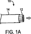
組織アクセスおよび撮像装置の一変形例を図1A〜図1Cの詳細な斜視図に示す。図1Aに示すように、組織撮像および操作アセンブリ10は、送達カテーテルまたはシース14を介して薄型形状で患者の体内に経脈管的に送達することができる。心臓の左心房の流出路に位置する僧帽弁などの組織を処置する場合、一般に、患者の外傷を最小限に抑えながら左心房に入れるまたはアクセスすることが望まれる。そのようなアクセスを非手術的に行うために、1つの従来的アプローチは、一般に経中隔法または中隔開口術と呼ばれる手術において右心房室から左心房室まで心房内中隔を貫通することを伴う。経皮弁修復および置換のような手術については、心臓の左心房室に対する経中隔アクセスにより、一般に動脈系に対して経皮的に入れることが可能なものよりも大きなデバイスを静脈系に入れることが可能になる。
A variation of the tissue access and imaging device is shown in the detailed perspective view of FIGS. 1A-1C. As shown in FIG. 1A, tissue imaging and
撮像および操作アセンブリ10を組織の撮像に利用する準備ができると、矢印で示すように、カテーテル14から撮像フード12を前に出し、カテーテル14の遠位側開口部より展開することができる。展開時には、図1Bに示すように、撮像フード12は、拘束が解かれて展開撮像構成に広がるかまたは開くことができる。撮像フード12は、例えば、ポリマー、プラスティック、または織布材料を含むがこれらに限定されない各種の適応または整合可能な生体適合性材料から製造することができる。織布材料の一例としては、Kevlar(登録商標)(E.I.du Pont de Nemours,Wilmington,DE)が挙げられるが、これはアラミドであり、本明細書に記載するような用途に十分な品質を維持する、例えば、0.001インチ未満の薄い材料にすることができる。さらに、撮像フード12は、周囲の流体または構造(すなわち、解剖学的もしくは機械的構造または器具)からのあらゆる反射光を最適化または軽減するために、半透明または不透明材料から各種の異なる色に作成することができる。いずれの場合も、撮像フード12は、均一な構造または骨組み支持構造に製造することができ、その場合には、ニチノールもしくはバネ鋼などの形状記憶合金またはプラスティックなどで作った骨組みに、ポリマー、プラスティック、または織布材料で被覆して製造してもよい。
When the imaging and
撮像フード12は、展開カテーテルまたはシース14と独立して平行移動可能な展開カテーテル16に接合部24で取り付けることができる。接合部24の取付は、任意の数の従来法によって行うことができる。展開カテーテル16は流体送達管腔部18を規定するとともに、組織を撮像するための光撮像ファイバまたはアセンブリを内部に配置可能な撮像管腔部20を規定することができる。展開時には、撮像フード12が開口エリアまたはフィールド26を規定する限り、例えば、円筒形状、図示するような円錐形状、半球形状など、任意の数の形状に撮像フード12を拡張してもよい。開口エリア26は、対象組織領域が撮像可能なエリアである。撮像フード12はまた、対象組織領域に設置または突合せするための非外傷接触縁部または端部22を規定してもよい。さらに、例えば、接触縁部または端部22において最大径まで展開した撮像フード12の直径は、典型的には、展開カテーテル16の直径よりも大きい(しかしながら、接触縁部または端部22の直径を展開カテーテル16の直径以下にしてもよい)。例えば、接触端部の直径は、展開カテーテル16の直径の1〜5倍の範囲とすることができる(可能であればさらに大きくするこができる)。図1Cは、展開構成の撮像フード12の端面図を示す。また、接触縁部または端部22ならびに流体送達管腔部18および撮像管腔部20も示している。
The
撮像および操作アセンブリ10は、図1D〜図1Fの側面図および端面図のそれぞれに示すように、例えば、同心円または偏心円管腔部などの誘導線管腔部をさらにその内部に規定していてもよい。展開カテーテル16は、体腔内で経脈管的に送ることができる誘導線17上をまたはそれに沿って上記システムが容易に通過できるように誘導線管腔部19を規定してもよい。そして、展開カテーテル16は、当該分野で一般に公知であるように、誘導線17上を送ることが可能である。
The imaging and
操作時には、撮像フード12を図1Bのように展開し、接触端部22に沿って撮像する組織領域に対して所望どおりに配置した後、置換流体によって開口エリア26が完全に満たされ、開口エリア26内からすべての流体28が押しのけられるまで、置換流体を流体送達口18を介して陽圧で送り込んでもよい。置換流体流は層流化してそれ自体の浄化作用を強化し、撮像フード12内への血液の再侵入の防止に役立てることができる。代替的に、展開する前に流体流を開始してもよい。置換流体(本明細書では撮像流体と呼ぶ場合もある)は、例えば、生理食塩水、水、血漿などの任意の生体適合性流体であって、それを介して相対的に歪みを生じることなく可視化を行なえるように十分に透明な流体を含んでもよい。代替的に、または加えて、任意の数の治療薬剤を流体内に懸濁するか、またはその流体自体を含み、開口エリア26に送り込まれた後、心臓および患者の体内を通過するようにしてもよい。
In operation, the
図1Gは、組織撮像および操作アセンブリ10の他の変形例を示す。この変形例では、アセンブリ10は、フード12内の「軸外」位置に配置される1つ以上の可視化素子52を含む。「軸外」構成の利点については後述する。しかしながら、本発明のアセンブリは、可視化素子52を1個から数個まで備えてもよい。例えば、アセンブリ10のいくつかの変形例では、フード12内の開口エリアの3次元撮像を可能にするために、少なくとも2つの可視化素子52を含んでもよい。例えば、素子52は、3次元画像を生成するためにフード12の周囲で十分に間隔を空けるようにしてもよい。図1Gに示す可視化素子の代わりまたはそれらに加えて光ファイバーを用いることが企図される。3D画像を得るためのさらなる手段としては、単一の撮像素子を、2つの異なる角度から標的ゾーンを見ることができる2つ以上のセグメントに分けることが挙げられる。例えば、そのような立体的可視化素子は、レンチキュラーレンズ層および光センサーアレイを含み、レンチキュラーレンズ層が複数のレンチキュラー素子を含み、サイトセンサーアレイが複数の光センサーを含み、選択した光センサーが所定の波長範囲の光を検出し、他の光センサーが他の所定波長範囲の光を検出し、各レンチキュラー素子が選択した光センサー群の前に位置し、異なる方向からの光を選択した光センサー群内の異なる光センサーに向けるようにしてもよい。次に、光景を処理して3D画像を作成する。そのような3D撮像装置の例は、共に「Optical Device」と題されたGoldsteinらの米国特許第6,396,873号および同第6,704,043号に見られる。これらはともにその全てを本明細書において参考として援用する。そのような製品は、Petah Tivak,IsraelのVisionsense,Inc.から供給可能である。3D画像を作成するさらなる方法としては、光ファイバーで作った2つの画像ガイドであって、僅かな距離(.1〜10mm)だけ間隔を空けたガイドを用い、それらの2つの画像を1つの一体的な3D画像として組み合わせることが挙げられる。
FIG. 1G shows another variation of tissue imaging and
図1Hは、図1Gの線1H−1Hに沿って切り取った断面図を示す。図示するように、カテーテル16の変形例には、カテーテル16の全長またはその一部に沿って延びるワイヤまたは光ファイバーを担持する同時押出チャネル32を含んでもよい。チャネル32は、その他の管腔部32のスペースを塞ぐことなく可視化素子と撮像装置の接続を可能にすることができる。これらのチャネルはまた、撮像検出器から患者の外部のセンサー/プロセッサに信号を伝える電線を収容することもできる。
FIG. 1H shows a cross-sectional view taken along
代替的に、チャネル32は、光源または光供給部を提供することができる。図1Iは、本発明に係るカテーテルの遠位端の他変形例を示す。この変形例では、カテーテルは、様々な管腔部32を含む。本明細書に記載のように、管腔部32を可視化、ワーキングチャネル、吸引、器具の送達などに用いてもよい。図1Iの変形例はまた、カテーテル16が多数の照明源36を有することも示している。これらの照明源は、小型の照明用光ファイバー、または通常用いられるような任意の他の照明源であってもよい。本発明の他の変形例では、管腔部38は、洗浄または他の流体を提供してもよい。
Alternatively, the
図1Jは、組織撮像および操作アセンブリ10の他の変形例を示す。この変形例のフード12では、可視化部品52および照明源36の両方がフード12の内面に位置する。また、上記のように、図面ではフード12が単一の可視化素子52および単一の照明源36(例えば、ファイバ、LED、他の発光源)を収容するように示しているが、このデバイスの変形例では、さらなる素子52または照明源を含んでもよい。
FIG. 1J shows another variation of tissue imaging and
図2Aおよび図2Bの例に見られるように、展開カテーテル16を操作し、下側に位置する撮像対象の組織領域(この例では、左心房室内の僧帽弁MVの環状部Aの一部)に対してまたはその近くに、展開した撮像フード12を配置することができる。図2Aに見られるように、周囲の血液30が撮像フード12の周囲および撮像フード12内に規定される開口エリア26内を流れると、不透明な血液30が妨げとなり、撮像管腔部20を介して下側に位置する環状部Aを観察することが困難である。そして、図2Bに示すように、生理食塩水などの半透明流体28が開口エリア26内の血液30を少なくとも部分的に、好ましくは完全に押しのけられるまで、流体送達管腔部18を介して断続的にまたは継続的に送り込むことができる。
As seen in the examples of FIGS. 2A and 2B, the
接触端部22は、下側に位置する組織と直接接触する必要はないが、少なくとも組織と近接して、開口エリア26からの清澄液28の流れを維持して血液30が開口エリア26内に相当量逆流することを抑えるようにすることが好ましい。接触端部22はまた、通常知られるようなシリコーンまたはポリウレタンなどのある程度の軟度を有するような軟質の弾性材料で構成することで、接触端部22と下側に位置する不均一なまたは凹凸を有する解剖学的組織表面とが適合し易くなるようにしてもよい。血液30が撮像フード12から押しのけられると、清澄液30を介して下側に位置する組織の画像を見ることができる。そして、この画像を記録するか、または治療手技を行うためのリアルタイムでの観察に利用することができる。流体28の正方向の流れを継続的に維持して、下側に位置する組織が鮮明に見えるようにすることができる。代替的に、撮像および記録に利用可能な組織の鮮明な光景が得られる時点まで一時的にまたは散発的に流体28を送り込み、その時点で流体流28を停止し、撮像フード12内に血液30が再滲出または逆流するようにしてもよい。この処理は、同じ組織領域または複数の組織領域で何度も繰り返してもよい。
The
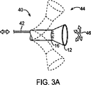
患者の体内の様々な領域に上記アセンブリを所望どおりに配置する際には、多種類の関節および操作制御機構を利用してもよい。例えば、図3Aの関節運動可能な撮像アセンブリ40に示すように、1本以上のプッシュプルワイヤ42を展開カテーテル16内に通し、デバイスの遠位端部分を様々な方向46に向けて操縦することにより、可視化する組織の領域の隣に撮像フード12を所望どおりに配置してもよい。利用するプッシュプルワイヤ42の位置取りおよび数に応じて、展開カテーテル16および撮像フード12を関節運動させて任意の数の構成44にしてもよい。手動により1つ以上の制御機構を利用して、1本または複数本のプッシュプルワイヤ42の近位端を介して患者の体外から関節運動させるようにしてもよい。代替的に、展開カテーテル16は、さらに後述するように、コンピュータ制御により関節運動させてもよい。
Many types of joints and manipulation control mechanisms may be utilized to place the assembly as desired in various regions within the patient's body. For example, as shown in the
加えて、または代替的に、1本以上のプッシュプルワイヤを介して関節運動可能であるとともに、1つの撮像管腔部および1つ以上の作用管腔部を有する関節運動可能な送達カテーテル48を、展開カテーテル16を介して撮像フード12内に送達してもよい。撮像フード12内の関節運動可能な送達カテーテル48の遠位部により、送達カテーテル48または展開カテーテル16を介して透明な置換流体を送り込み、撮像フード12内のフィールドを鮮明にしてもよい。図3Bに示すように、関節運動可能な送達カテーテル48を撮像フード内で関節運動させて、撮像フード12に隣接する組織のより良好な画像が得られるようにしてもよい。さらに、関節運動可能な送達カテーテル48を関節運動させて、下記で詳述するように、展開カテーテル16を配置換えしたり、フード12内の撮像フィールドを再度鮮明にする必要なく、カテーテル48を通る機器または器具を、撮像フード12を介して、撮像した組織の特定の領域に方向づけるようにしてもよい。
Additionally or alternatively, an
代替的に、関節運動可能な送達カテーテル48を展開カテーテル16に通すのではなく、図3Cに示すように、展開カテーテル16の遠位部分自体が、撮像フード12内で関節運動可能な遠位端49を備えるようにしてもよい。撮像方向の設定、機器送達などは、撮像フード12内で撮像した下側に位置する組織の特定の領域に対する展開カテーテル16内の1つ以上の管腔部を介して直接行うことができる。
Alternatively, instead of passing the
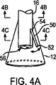
撮像フード12内の可視化は、上述のように、展開カテーテル16内に規定された撮像管腔部20を介して行うことができる。そのような構成では、可視化は、直線的な様式で行うことができる(すなわち、画像は、遠位側のフィールドから展開カテーテル16によって規定された長手軸に沿って生成される)。代替的に、または加えて、図4Aに示すように、枢動可能な支持部材50を有する関節運動可能な撮像アセンブリを展開カテーテル16に接続もしくは設置するか、またはその内部を通過させて、展開カテーテル16によって規定される長手軸に対して軸外で可視化するようにしてもよい。支持部材50の遠位端に撮像素子52(例えば、CCDもしくはCMOS撮像装置または光ファイバー)を取り付け、近位端を枢動接続部54を介して展開カテーテル16と接続してもよい。
Visualization in the
撮像に1本以上の光ファイバーを利用する場合、図4Bの断面図に示すように、展開カテーテル16に光ファイバー58を通して支持部材50に経由させてもよい。光ファイバー58の使用により、診断および/または治療器具を通過させる展開カテーテル16内の1つまたは数個の管腔部56の直径サイズを増大させることができる。代替的に、光ファイバー58の代わりに、通常知られる電荷結合素子(CCD)またはCMOS撮像装置などの電子チップを利用してもよく、その場合には、電子撮像装置を展開カテーテル16の遠位部分に配置し、展開カテーテル16の近位側から電線を通してもよい。代替的に、画像を無線送信するために、電子撮像装置を受信器に無線接続してもよい。下記においてさらに詳述するように、さらなる光ファイバーまたは発光ダイオード(LED)を用いて画像または手術室用の照明を提供することができる。支持部材50を接続部54を介して枢動可能とすることで、図4Cの断面図に示すように、カテーテル16の遠位部分に規定されたチャネルまたは溝60内に部材50を薄型構成で配置できるようにしてもよい。患者の体内に展開カテーテル16を血管内送達する最中に、撮像フード12も薄型構成にした状態で、支持部材50をチャネルまたは溝60内に配置することができる。可視化の最中には、図4Aのように、撮像フード12を拡張して展開構成にするとともに、支持部材50を展開して軸外構成にし、フード12に隣接する組織を撮像することができる。所望に応じて、支持部材50の他の構成を軸外での可視化に利用してもよい。
When one or more optical fibers are used for imaging, the
図4Dは、軸外で可視化する能力を備えた組織撮像および操作アセンブリ10の他の変形例を示す。図4Dに示すように、(典型的には、ある部位に誘導されたときに)フード12は折畳位置にあるとき。この変形例では、可視化素子52は、特に、アセンブリ10を所望の部位に配置する最中に、アセンブリ10の軸と一致するように構成される。
FIG. 4D shows another variation of tissue imaging and
図4Eは、図4Dのアセンブリ10が標的部位に達した様子を示す。図示するように、フード12が拡張し開口エリアを規定している。次に、可視化素子52が関節運動しカテーテル16からずらすことができる。この構成により、送達中にデバイスが薄型の送達状態となり、その後、拡張して開口エリアを規定することが可能になる。可視化素子52の「軸外」に配置換えする能力により、アセンブリ10がカテーテル16に大型の作用器具を収容し、可視化素子の収容に必要な空間を実施的に低減することができる。本発明では、同様に光ファイバーを配置し、図面に描かれているように、それらのファイバが可視化素子52と同様に「軸外」に配置換えすることも企図する。軸外での可視化により、術中の光景を、霊長動物の目および手の相互配置と似通ったより自然なものにすることができる。
FIG. 4E shows the
図4Fおよび図4Gは、可視化素子52がフード12の内外に摺動可能なアセンブリ10を示す。例えば、図4Fに示すような展開時には、可視化素子52は、フード12の内側に沿って位置する。図4Gに示すような折畳位置では、可視化素子52は、フード12の外側まで延在する。この変形例は、可視化素子52を収容することなくフード12を圧縮するかまたは折り畳んで小型化できるために有用である。また、デバイス10を所望の部位に誘導する際に可視化素子52を用いることができる。
4F and 4G show the
図5は、対象組織領域が撮像アセンブリ10を介して観察されている心臓Hの説明断面図を示す。この例では、送達カテーテルアセンブリ70を患者の脈管系に経皮的に入れ、上大静脈SVCを介して右心房RA内に進入させることができる。送達カテーテルまたはシース72を関節運動させて心房中隔ASから左心房LA内に入れ、僧帽弁MVの周囲の組織(例えば、環状部A)を観察または治療することができる。図示するように、展開カテーテル16および撮像フード12を送達カテーテル72から出し、対象組織領域と接触または近接させる。他の例では、所望であれば、送達カテーテルアセンブリ70を下大静脈IVC内に送ってもよい。さらに、撮像アセンブリ10で心臓Hの他の領域(例えば、右心室RVまたは左心室LV)にアクセスして撮像または治療を行ってもよい。
FIG. 5 shows an illustrative cross-sectional view of the heart H where the target tissue region is observed through the
心臓Hの領域または体の他の部分にアクセスする場合には、送達カテーテルまたはシース14は、従来の血管内カテーテルまたは管腔内送達デバイスを備えてもよい。代替的に、本明細書に記載の撮像アセンブリとともにロボット制御された送達カテーテルを任意で利用してもよく、その場合には、コンピュータコントローラ74を用いて送達カテーテル14の関節運動および位置取りを制御してもよい。利用可能なロボット制御送達カテーテルの一例は、「Flexible Instrument」と題されたBrockらの米国特許公報2002/0087169A1にさらに詳述されており、本明細書においてその全てを参考として援用する。Hansen Medical,Inc.(Mountain View,CA)により製造される他のロボット制御送達カテーテルも送達カテーテル14とともに利用可能である。
When accessing a region of the heart H or other part of the body, the delivery catheter or
手術中の展開カテーテル16の安定化を容易にするために、図6Aに示すように、1つ以上の膨張式バルーンまたはアンカー76をカテーテル16の長さ方向に沿って配置してもよい。例えば、心房中隔ASを経て左心房LA内にアプローチする経中隔的方法を利用する場合、膨張式バルーン76を膨張させて薄型構成から拡張構成にし、心臓Hに対するカテーテル16の位置を一時的に固定または安定させるようにしてもよい。図6Bは膨張した第1のバルーン78を示し、図6Cは第1のバルーン78の近位で膨張した第2のバルーン80を示す。このような構成では、隔壁ASは、バルーン78、80間に押し込められるかまたは挟まれて、カテーテル16および撮像フード12を一時的に安定させることができる。一方のバルーン78、またはバルーン78、80の両方を用いてもよい。他の代替例では、拡張可能なメッシュ部材、マルコー(malecots)、または任意の他の一時的に拡張可能な構造を利用してもよい。手術が終了した後、バルーンアセンブリ76を収縮または再構成して薄型形状にし、展開カテーテル16を取り除くことができる。
To facilitate stabilization of the
撮像する組織表面に対する撮像フード12の位置をさらに安定させるために、各種の固定機構を任意で用いて撮像フード12を組織上に一時的に保持してもよい。そのような固定機構は、移動しやすい組織の撮像(例えば、拍動中の心臓室内の組織を撮像する場合)に特に有用であり得る。少なくとも1つの機器用管腔および任意の可視化管腔を有する器具送達カテーテル82を、展開カテーテル16を介して拡張した撮像フード12内に送達してもよい。撮像フード12が検査する組織表面Tと接触すると、図7Aに示すように、弦巻状組織貫通デバイス84などの固定機構を器具送達カテーテル82に通して撮像フード12内に入れてもよい。
In order to further stabilize the position of the
弦巻状組織係合デバイス84は、患者の体外の近位端から回転力を与えられ、下側に位置する組織表面Tに一時的に固定されるようにすることができる。図7Bの矢印で示すように、弦巻状組織係合デバイス84は、組織T内に埋め込まれると、展開カテーテル16の近位側に引き寄せられ、展開カテーテル16および撮像フード12が遠位側に押されることにより、撮像フードの接触端部または縁部22を組織Tに対して軽く押し付けることができる。展開カテーテル16に対する組織係合デバイス84の位置を一時的に固定し、撮像フード12内での診断または治療手技中に撮像フード12の位置を確実に固定することができる。手術後、近位端に逆方向の回転力を与えて組織係合デバイス84を組織から離して組織Tからアンカーを取り除き、展開カテーテル16を組織の他の領域に再配置して固定プロセスを繰り返すかまたは患者の体内から取り除いてもよい。組織係合デバイス84はまた、他の公知の組織係合器具、特に、陰圧吸引補助係合または捕捉器具補助係合器具で構成してもよい。
The coiled
弦巻状アンカー84を示したが、これは例示を目的としたものであり、例えば、かぎ状もしくは有刺アンカーまたは捕捉器具などの他の種類の一時的なアンカーを利用してもよい。さらに、器具送達カテーテル82全体を省略してもよく、展開カテーテル16内に規定される管腔を直接介して固定デバイスを送達してもよい。
Although a
器具送達カテーテル82全体を省略し撮像フード12を一時的に固定する他の変形例に関して、図7Cは、1つ以上の管状支持部材86(例えば、図示するように4つの支持部材86)と一体化した撮像フード12を示す。管状支持部材86はその内部に管腔を規定しており、各管腔内には、弦巻状組織係合器具88が配置される。拡張した撮像フード12を組織に一時的に固定する場合、弦巻状組織係合器具88を遠位側に推進し撮像フード12から延在させ、それらの各々に近位端から回転力を与えて下側に位置する組織Tと係合させることができる。各弦巻状組織係合器具88は、撮像フード12の送達および展開中に、展開カテーテル16の長さ方向に沿って送るかまたは管状支持部材86内に配置されてもよい。撮像フード12内の手術が終了すると、各組織係合器具88を組織から取り外し、撮像フード12を組織の他の領域に配置換えするかまたは患者の体内から取り除いてもよい。
For other variations that omit the entire
図8Aに流体送達システム90に接続されるとともに、任意のプロセッサ98ならびに画像レコーダーおよび/またはビューワー100に接続された組織撮像アセンブリを例示する。流体送達システム90は、一般に、ポンプ92を備えるとともに、当該システムに流入する流体の流量を制御する任意の弁94を備え得る。ポンプ92と流体接続された流体リザーバー96は、撮像フード12を介して送り込まれた流体を保持することができる。任意の中央処理装置またはプロセッサ98は流体送達システム90と電気通信を行い、送り込まれた流体の流量および/または速度などの流動パラメータを制御することができる。プロセッサ98はまた、画像レコーダーおよび/またはビューワー100と電気通信を行い、撮像フード12内から受信した組織の画像を直接見ることもできる。撮像レコーダーおよび/またはビューワー100は、画像だけでなく、所望であれば、観察した組織領域の位置を記録するために用いてもよい。
FIG. 8A illustrates a tissue imaging assembly connected to the fluid delivery system 90 and connected to an optional processor 98 and image recorder and / or
任意に、流体流および画像の取り込みの調整にプロセッサ98を利用してもよい。例えば、プロセッサ98は、血液を組織エリアから押しのけて鮮明な画像が得られるまでリザーバー96から流体流を供給するようにプログラムしてもよい。施術者の目視によって、またはコンピュータによって画像が十分に鮮明であると判定されると、当該組織の画像をレコーダー100によって自動的に取り込み、ポンプ92をプロセッサ98によって自動的に停止または減速し、患者に対する流体流の流入を止めてもよい。流体送達および画像の取り込みの他の変形例も当然可能であり、上記構成は例示のみを目的としたものであり限定のためのものではない。
Optionally, processor 98 may be utilized to adjust fluid flow and image capture. For example, the processor 98 may be programmed to dispense fluid flow from the
図8Bは、流体送達/組織操作システム110の携帯型変形例のさらなる例を示す。この変形例では、システム110は、患者の体外で医師が携帯または操作可能なハウジングまたはハンドルアセンブリ112を有し得る。流体リザーバー114(この変形例では注射器として示されている)は、ハンドルアセンブリ112と流体接続可能であり、送出機構116(例えば、送りネジ)を介して作動可能である。流体リザーバー114は、ハンドルアセンブリ112から分離するとともに、ハンドルアセンブリ112と1本以上の管を介して流体接続した簡易リザーバーであってもよい。流体流量および他の機械的作用は、電子コントローラ118で測定可能である。
FIG. 8B shows a further example of a portable variation of the fluid delivery /
撮像フード12の展開は、ハンドルアセンブリ112上に位置するフード展開スイッチ120によって行われてもよく、リザーバー114からの流体の吐出は、コントローラ118と電気的に結合可能な流体展開スイッチ122によって行ってもよい。コントローラ118はまた、図示するように、ハンドルアセンブリ112と任意で一体化した有線または無線アンテナ124と電気的に結合してもよい。無線アンテナ124を用いて、撮像フード12から取り込んだ画像を、例えば、Bluetooth(登録商標)無線技術(Bluetooth SIG,Inc.,Bellevue,WA)、RFなどにより受信器に無線送信し、モニタ128上で観察したり、後で観察するために記録することができる。
Deployment of the
展開カテーテル16の関節制御、または展開カテーテル16を送達可能な送達カテーテルもしくはシース14の関節制御は、上述のように、コンピュータ制御によって行ってもよく、その場合には、ハンドルアセンブリ112とともにさらなるコントローラを利用してもよい。手動による関節運動の場合、ハンドルアセンブリ112は、展開カテーテル16の配置を手動で操作するための1つ以上の関節制御機構126を組み込んでもよい。ハンドルアセンブリ112はまた、さらに後述するように、撮像フード12内での組織の操作および治療のために多数の血管内器具を通すことが可能な1つ以上の機器ポート130を規定してもよい。さらに、特定の手術では、任意に、吸引ポンプ132をハンドルアセンブリ112と流体結合するか、または展開カテーテル16と直接流体結合することによって、流体または堆積物を撮像フード12内に吸引して患者の体から排出してもよい。
Joint control of the
上述のように、流体を撮像フード12内に継続的に送り込んで下側に位置する組織を鮮明に見えるようにしてもよい。代替的に、撮像および記録に利用可能な組織の鮮明な光景が得られる時点まで一時的にまたは散発的に流体を送り込み、その時点で流体流を停止し、撮像フード12内に血液が再滲出または逆流するようにしてもよい。図9A〜図9Cは、組織の複数の領域でいくつかの画像を取り込む例を示す。展開カテーテル16を所望どおりに配置し、撮像フード12を展開して、撮像する組織Tのある領域上に配置することができる(この例では、組織は患者の心臓の左心房内の僧帽弁MVの周囲に位置する)。撮像フード12は、上述のように、任意に、組織に固定された後、撮像流体をフード12内に送り込むことにより洗浄することができる。十分に洗浄した後、組織を可視化して、制御電子回路118によって画像を取り込むことができる。第1の取り込み画像140は、図9Aに示すように、医師が観察するために、無線124によってモニタ128に格納および/または送信してもよい。
As described above, the fluid may be continuously fed into the
そして、図9Bに示すように、展開カテーテル16を僧帽弁MVの隣接部分に配置換えすることができ、このプロセスを繰り返し行って第2の画像142を観察および/または記録のために取り込んでもよい。図9Cに示すように、展開カテーテル16を組織の他の領域に再度配置換えし、第3の画像144を観察および/または記録のために取り込んでもよい。この手順を必要な回数だけ繰り返し、僧帽弁MVの周囲の組織または任意の他の組織領域の広範な画像を取り込んでもよい。展開カテーテル16および撮像フード12を組織領域間で配置換えする際、上記のように、撮像フード12が洗浄可能な場合には、配置中にポンプを停止し、組織が撮像されるまで血液または周囲の流体が撮像フード12内に入るようにしてもよい。
Then, as shown in FIG. 9B, the
上述したように、血液または他の体液を一掃し、内部に撮像流体を送り込むことによって撮像フード12を洗浄すると、フード12内の撮像流体を陽圧に維持するために流体を継続的に送り込むか、またはフード12内への流体流をコンピュータ制御下で送り込み、各種のパラメータの検出時に、または下側に位置する組織の鮮明な画像が得られるまで遅延または停止するようにしてもよい。制御電子回路118はまた、撮像フード12に流入する流体流を各種物理的パラメータで調節し、撮像フード12内の鮮明な画像を維持するようにプログラムしてもよい。
As described above, when the
一例として撮像フード12内の流体圧力と周囲の血圧とを釣り合わせる様子を図示するグラフ150を図10Aに示す。グラフ150は、患者の心臓の拍動運動により時間Tにおいて拡張期血圧152と収縮期血圧154を交互に繰り返す周期的な血圧156を示す。曲線160で示す撮像フード12内の撮像流体の流圧は、血圧変化160に対応して自動的にタイミングを取り、ピーク収縮期血圧158における圧力差で示すように、撮像フード12内の圧力上昇を常に血圧156より微増分ΔPだけ上に維持するようにできる。周囲の血圧の圧力変化に対して、この圧力差ΔPを撮像フード12内で維持することにより、撮像フード12内の正の撮像流圧を維持し、下側に位置する組織の光景を鮮明に維持することができる。定数ΔPを維持することの1つの利点は、一定した流動、および鮮明なフィールドの維持である。
As an example, a
図10Bは、下側に位置する組織の鮮明な光景を維持する他の変形例を示すグラフ162を示しており、下記においてさらに詳述するように、撮像フード12内の1つ以上のセンサーが撮像フード12内の圧力変化を検知し、それに応じて撮像フード12内の撮像流体の圧力を上昇するように構成可能である。これによって、循環血圧156からずらした流体圧力160で示すように、時間遅延ΔTが生じるが、この時間遅延ΔTは、下側に位置する組織の鮮明な画像の維持に関しては無視してもよい。この時間遅延を実質的になくすために、予測ソフトウェアアルゴリズムを用いて次の圧力波ピークが到達するときを予測するとともに、圧力波の到達よりも前述の時間遅延と実質的に等しい時間量だけ先に圧力を上昇させて本質的にその時間遅延を相殺してもよい。
FIG. 10B shows a graph 162 illustrating another variation that maintains a clear view of the underlying tissue, and as described in more detail below, one or more sensors within the
撮像フード12内の流体圧力の変動は、部分的には、撮像フード12の性質によって発生し得る。従来より組織の撮像に利用される膨張式バルーンは、周囲の血圧変化に影響され得る。一方、撮像フード12は、その内部容量を一定に保ち、構造的には周囲の血圧変化に影響されないため、内部で圧力を上昇させることができる。フード12を構成する材料は、このフード12内の圧力調整方法にも寄与する。高デュロメーターポリウレタンまたはナイロンなどのより固いフード材料は、展開時に開いたフードの維持を容易にする。一方、低デュロメーターPVCまたはポリウレタンなどの相対的にデュロメーター値が低い、すなわち、柔軟な材料は、周囲の流体圧力によって折り畳まれ、展開または拡張したフードを十分に維持することができない。
Variations in fluid pressure within the
ここで撮像フードに着目すると、撮像フード174内にさらなる撮像バルーン172を備えた他の変形例を示す図11Aに示すように、組織撮像アセンブリの他の変形例を利用することができる。この変形例では、半透明の皮膜を有する拡張式バルーン172を撮像フード174内に配置することができる。バルーン172は、可視化を可能にする十分な半透明特性を有する任意の伸張性生体適合性材料で構成できる。撮像フード174を対象組織領域上に展開すると、バルーン172に流体(例えば、生理食塩水が好ましいが、気体であってもよい)を充填し、血液が十分に押しのけられるまでバルーン172を拡張させることができる。このようにして、観察する組織領域の近位でまたはそれに接触するようにしてバルーン172を拡張することができる。バルーン172には、その配置に役立てるために、造影剤を充填して蛍光透視法で観察可能にすることもできる。そして、展開カテーテル170内に配置した撮像装置(例えば、光ファイバー)を利用し、バルーン172を介して組織領域を観察することができるとともに、バルーン172の近位側において展開カテーテル170の一部に沿って配置可能な1つ以上の任意の流体ポート176を介して撮像フード174に送り込むことが可能な任意のさらなる流体を観察することができる。代替的に、バルーン172の表面には、内部に入れた流体の滲出または通過を可能にし、撮像フード174内から血液を逃して押しのける1つ以上の穴を規定してもよい。
Turning now to the imaging hood, other variations of the tissue imaging assembly can be utilized, as shown in FIG. 11A, which shows another variation with a further imaging balloon 172 within the imaging hood 174. In this variation, an expandable balloon 172 having a translucent coating can be placed in the imaging hood 174. Balloon 172 can be composed of any extensible biocompatible material that has sufficient translucency properties to allow visualization. When the imaging hood 174 is deployed over the target tissue region, the balloon 172 is filled with a fluid (eg, physiological saline is preferred, but may be gas) and the balloon 172 is expanded until the blood is sufficiently displaced. Can do. In this way, the balloon 172 can be expanded proximally to or in contact with the tissue region to be observed. The balloon 172 can be filled with a contrast agent so that the balloon 172 can be observed by fluoroscopy in order to make use of the arrangement. A tissue region can be observed via the balloon 172 using an imaging device (for example, an optical fiber) disposed in the
図11Bは、バルーン180が単独で利用される他の代替例を示す。展開カテーテル178に取り付けられたバルーン180には、生理食塩水または造影剤などの流体を充填することが可能であり、撮像する組織領域と直接的に接触させることが好ましい。
FIG. 11B shows another alternative where the
図12Aは、展開カテーテル16が上述のような撮像フード12を組み込んでおり、撮像フード12内にさらなる柔軟膜182を含む他の代替例を示す。柔軟膜182は、カテーテル16の遠位端に取り付けられるとともに、任意で接触端部22にも取り付けられてもよい。撮像フード12は上記のように利用可能であり、膜182は、体内において、または患者内でカテーテル16を配置する前にカテーテル16から展開され、撮像フード12内の容積を低減するようにしてもよい。容積を低減または抑えることにより、可視化のために吐出される流体の量を低減するか、または可視化する組織のエリアに応じて低減することができる。
FIG. 12A shows another alternative in which the
図12Bおよび図12Cは、図示するように、撮像フード186を展開カテーテル184内で近位側に引き込むかまたはカテーテル186から遠位側に展開して撮像フード186の容積を変化させることによって吐出する流体の体積を低減するさらに他の代替例を示す。図12Bでは、例えば、環状管腔部188などのカテーテル184内で外周が規定された管腔部から撮像フード186の一部が展開している様子が見られる。下側に位置する組織は、部分的に展開した撮像フード186を用いて可視化することができる。代替的に、図12Cに示すように、撮像フード186’は、環状管腔部188から当該フード186’を遠位側に推進することによって完全に展開することができる。この拡張構成では、フード186’の周囲を拡張することにより、可視化する組織の面積を広げることができる。
12B and 12C, as shown, eject the
図12Dは、組織撮像および操作アセンブリ10の他の変形例を示す。この変形例では、フード12は、流体源522に結合された膨張式部材520(例えば、バルーン、空気袋、または充填可能な膜)を含む。膨張式部材520は、透明な材料で作ることができる。フード12の拡張時には、図12Eに示すように、膨張式部材520に清澄液が充填される。膨張式部材520が拡張していくにつれて、(矢印で示すように)フード12内の流体および他の物質が押しのけられる。部材520および流体は透明であるため、この場合においても、可視化素子52はフード12の開口エリア内の組織を可視化することができる。図12Eは、本明細書に記載のアセンブリ10のさらに他の原理を示す。この変形例では、フード12は、2つ以上の膨張式部材520、524を含む。膨張式部材520、524は、フード12から流体を押しのけながら可視化を可能にするように機能する。しかしながら、2つ以上の膨張式部材520、524を使用することで、膨張式部材の間に器具またはデバイス526を送ることが可能になる。他の変形例では、膨張式部材は、置換液の屈折率に近いかまたはそれと一致する屈折率を有する材料から作られる。この屈折率の選択により、本質的に膜を「消し」て可視化の妨げにならないようにすることができる。
FIG. 12D shows another variation of tissue imaging and
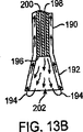
図13Aおよび図13Bは、それぞれ、組織の可視化の最中に患者の心臓または他の体腔に注入する流体量を最小化する流体吸引システムを利用可能な撮像アセンブリのさらに他の変形例の斜視図および側断面図を示す。この変形例の展開カテーテル190は、展開カテーテル190と一体化するかまたは独立して平行移動することが可能な内部管状部材196を規定し得る。部材196内に規定された流体送達管腔部198は、その接触縁領域に渡って1つ以上の開口チャネル194が規定され得る撮像フード192と流体接続可能である。よって、流体送達管腔部198を介して送出される流体は開口エリア202を満たし、その内部からあらゆる血液または他の流体もしくは物体を押しのけることができる。清澄液が開口エリア202から押し出されるとすぐに、1つ以上のチャネル194に吸引されるかまたは吸い込まれ、展開カテーテル190に戻るようにすることができる。管状部材196も任意の器具または可視化デバイスを通過させるためのさらなるワーキングチャネル200を1つ以上規定してもよい。
FIGS. 13A and 13B are perspective views of yet another variation of an imaging assembly that can utilize a fluid aspiration system that minimizes the amount of fluid that is injected into a patient's heart or other body cavity during tissue visualization, respectively. And shows a cross-sectional side view. This variation of the
本明細書に記載の各例において撮像フードを展開する際に、図14A〜図14Dの例に示すように、送達カテーテル内で薄型形状での送達のための配置または構成するときには、撮像フードが任意の数の構成を取るようにすることができる。これらの例は、例示を目的としたものであ、範囲を限定するためのものではない。図14Aは、複数の折り目に沿ってフード212を折ることにより撮像フード212がカテーテル210内で圧縮可能である一例を示す。フード212はまた、例えば、ニチノール、エルジロイ(Elgiloy)、形状記憶高分子、電気活性高分子、またはばね用ステンレス鋼などの超弾性もしくは形状記憶材料または合金からなる支持体(scaffolding)またはフレーム214を備える。この形状記憶材料は、カテーテル210に拘束された状態から矢印の方向に推進されると、撮像フード212を拡張または展開して拡張構成となるように作用する。
When deploying the imaging hood in each example described herein, the imaging hood may be configured or configured for delivery in a thin shape within a delivery catheter, as shown in the examples of FIGS. 14A-14D. Any number of configurations can be employed. These examples are for illustrative purposes and are not intended to limit the scope. FIG. 14A shows an example where the
図14Bは、折り畳まれ重複した構成の撮像フード216がカテーテル210から拡張または展開可能である他の例を示す。フレームまたは支持体214は、この例においても利用可能である。図14Cは、撮像フード218を回転、反転、または裏返しすることにより展開することができるさらに他の例を示す。さらに他の例に関して、図14Dは、圧縮するだけで撮像フード220を薄型形状にすることができる高い弾性を有する材料からフード220が製造されている構成を示す。特に、例えば、ニチノールなどの形状記憶または超弾性材料の支持体またはフレームを利用して作製している場合には、フード220のこの薄型圧縮形状を解除するだけで、展開構成に拡張することができる。
FIG. 14B illustrates another example where the
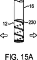
撮像フードを拡張する他の変形例を、弦巻状に拡張するフレームまたは支持部230を例示する図15Aおよび図15Bに示す。図15Aに示す拘束された薄型構成では、弦巻状フレーム230は、撮像フード12の膜と一体化することができる。図15Bに示すように拡張のために拘束を解くと、弦巻状フレーム230は円錐または先細形状に拡張してもよい。代替的に、弦巻状フレーム230を加熱活性化ニチノールで作り、電流の印加時に拡張するようにしてもよい。
Another variation for expanding the imaging hood is shown in FIGS. 15A and 15B illustrating a frame or
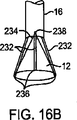
図16Aおよび図16Bは、撮像フード12がフード膜と一体化した1つ以上のフード支持部材232を備えるさらに他の変形例を示す。これらの長手方向に取り付けられた支持部材232は、近位端が展開カテーテル16に枢動可能に取り付けることができる。展開カテーテル16の長さ方向に沿って1本以上のプルワイヤ234を通し、展開カテーテル16内に規定された1つ以上の開口部238から撮像フード12の近位側まで延在させ、プルワイヤ取付点236において対応する支持部材232に取り付けることができる。支持部材232は、プラスティック、またはステンレス鋼などの金属で製造してもよい。代替的に、支持部材232は、プルワイヤを使用または必要とすることなく展開構成に自己拡張可能なニチノールなどの超弾性または形状記憶合金で作ってもよい。熱エネルギーまたは電気エネルギーを加えると拡張する加熱活性化ニチノールを用いることも可能である。他の代替例では、例えば、PETバルーンを利用し、支持部材232を膨張式管腔部として構成してもよい。図16Aに示す薄型送達構成では、1本以上のプルワイヤ234に対して患者の体外の近位端から張力をかけ、対応する支持部材232を引いて図16Bに示すような展開構成にして撮像フード12を拡張してもよい。撮像フード12を薄型構成に戻す際には、展開カテーテル16を近位側に引いて拘束するカテーテルに入れるか、またはプルワイヤ234を単に遠位部に押して撮像フード12を折り畳んでもよい。
16A and 16B show still another modification in which the
図17Aおよび図17Bは、撮像フード膜を支持する長手方向に配置された支持部材242を少なくとも2つ以上有する撮像フード240のさらに他の変形例を示す。各支持部材242は、支持部材242間を対角線上に延び、枢動可能に取り付けられた交差支持部材244を有する。各交差支持部材244は、支持部材242間の交差部分で相互に枢動可能に取り付けることができる。ジャッキまたはねじ部材246は、この交差地点で各交差支持部材244と結合することができ、回転力を供給可能なワイヤ248などの回転力供給部材は、各ジャッキまたはねじ部材246と結合し、近位側から展開カテーテル16を介して患者の体外まで延在するようにできる。患者の体外から、回転力を供給可能なワイヤ248に回転力を与えてジャッキまたはねじ部材246を回転し、これにより、交差支持部材244を推進し相互に角をなすようにすることで支持部材242を相互に遠ざかるように推進することができる。このようにして、ワイヤ248に回転力を与えることにより、撮像フード240を、図17Aに示す薄型から図17Bに示す拡張型に変化させるともとに、薄型に戻るようにすることができる。
17A and 17B show still another modification of the
図18Aおよび図18Bは、撮像フードおよびその展開に関するさらに他の変形例を示す。図示するように、展開カテーテル16は、遠位部分にいくつかの枢動部材250(例えば、2〜4個の部品)を有するようにすることができ、これらは、図18Aに示すように、薄型構成において管状形状を形成する。展開カテーテル16を軸にして半径方向に枢動する場合、図18Bに示すように、枢動部材250が開くことにより、枢動部材250間の間隙に延在する伸張性または拡張性膜252を有する展開構成とすることができる。伸張性膜252を、例えば、接着剤などの各種の方法で枢動部材250に取り付けることにより、枢動部材250が完全に延びきって円錐形状になると、枢動部材250および膜252が撮像フードとして使用される円錐形状を形成するようにすることができる。伸張性膜252は、メッシュもしくはPTFEなどの多孔質材料から、またはポリウレタン、PVC、ナイロンなどの半透明もしくは透明高分子から作ることができる。
FIG. 18A and FIG. 18B show still another modification regarding the imaging hood and its development. As shown, the
図19Aおよび図19Bは、展開カテーテル16の遠位部分が柔軟な金属またはポリマー材料から製造され半径方向に拡張するフード254を形成することができるさらに他の変形例を示す。図19Aに示すように、複数のスロット256が展開カテーテル16の遠位部分に一定のパターンで形成され得る。スロット256は、図19Bに示すように、上記の方法のいずれかを利用して遠位部分が半径方向に推進されて開くと、各スロット256が拡張して開口部となり半径方向に拡張する円錐形状のフード254が形成できるようなパターンに形成可能である。伸張性膜258はフード254の外面または内面上に位置し、流体不透過性フード254を形成することで、フード254を撮像フードとして利用できるようにすることができる。あるいは、伸張性膜258を、代替的に、各開口部258に形成することで流体不透過性フード254を形成してもよい。撮像手順が終了すると、フード254を収縮して薄型構成にすることができる。
19A and 19B show yet another variation in which the distal portion of the
撮像フードのさらに他の構成は、撮像フードが重複パターンで相互に重なり合う複数の重複フード部材260で形成される図20Aおよび図20Bに見ることができる。図20Bに示すように、各フード部材260は、拡張時に、展開カテーテル16から外側に向かって半径方向に延び、円錐形状の撮像フードを形成することができる。隣接するフード部材260は、重複接合部分262に沿って相互に重なり合い、撮像フード内に流体保持表面を形成することができる。さらに、フード部材260は、任意で対象組織領域から周囲の組織を引き離すために十分な強度を有する任意の数の生体適合性材料(例えば、ニチノール、ステンレス鋼、高分子など)から作ることができる。
Yet another configuration of the imaging hood can be seen in FIGS. 20A and 20B where the imaging hood is formed of a plurality of overlapping
図20Cは、本発明によるフード12の他の変形例を示す。この変形例では、フード12は、少なくとも一方の側で重なる複数の部品264を含む。重複部品264は、不規則な形状の組織に対してフードの遠位端を適合させる際に役立つ。重複部品264は、フード12の端部に付加することができる。代替的に、重複部品は、実質的にフードの長さ方向に沿って延在するようにしてもよい(図示せず)。任意の数の部品264をフードとともに用いることが可能である。例えば、不規則な表面を有する組織に対して用いる場合、このデバイスは、フード12の端部が「ブラシ状の」概観を有するように多数の部品を有してもよい。代替的に、このデバイスの変形例では、より少数(2つ程度)の部品を有するようにしてもよい。そのような変形例では、相対的に滑らかな組織表面に対して使用するために適切に構成してもよい。部品264は、高分子、布、または膜を充填した構造物で製造してもよい。部品264は、構造様式に関わらず、組織に対するフードの適合性を改善する。
FIG. 20C shows another modification of the
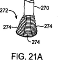
一般に、撮像フードが正しい向きで組織表面と接触することが望まれるが、代替的に、撮像フードが組織表面と鋭角で接触するように構成してもよい。組織に対してそのように接触するように構成された撮像フードはまた、予測不可能なまたは不均一な解剖学的輪郭を有する組織表面との接触に特に適している。例えば、図21Aの変形例に示すように、展開カテーテル270が特に柔軟に構成された撮像フード272を有するようにしてもよい。この変形例では、撮像フード272は、例えば、折り目が付けられた表面を利用することにより、折ることまたは折り畳むことができるように構成される1つ以上の部品274を備えてもよい。よって、図21Bに示すように、撮像フード272が不均一な組織表面Tと接触する場合、部品274は、組織と密に適合することができる。これらの部品274は、例えば、心臓の肉柱との適合、または様々な体腔内に見られる不均一な生体構造との適合を可能にするアコーディオン型構造を利用することにより、個別に折り畳むことができる。
In general, it is desirable for the imaging hood to contact the tissue surface in the correct orientation, but alternatively, the imaging hood may be configured to contact the tissue surface at an acute angle. An imaging hood configured to make such contact with tissue is also particularly suitable for contacting tissue surfaces with unpredictable or non-uniform anatomical contours. For example, as shown in the modification of FIG. 21A, the
さらに他の代替例に関して、図22Aは、撮像フード282が展開カテーテル280に取り付けられた他の変形例を示す。接触縁部または端部284は、接触端部284の周囲に配置された1つ以上の電気接点286を備えることができる。電気接点286は組織と接触するように構成可能であるとともに、例えば、血液と組織間の差動インピーダンスを測定することにより、組織と接触しているか否かを確実に示すように構成することができる。代替的に、接点286と電気通信を行うプロセッサ(例えば、プロセッサ98)を、どのような組織が電気接点286と接触しているかを判定するように構成してもよい。さらに他の代替例では、心臓組織の電位分布図を作成した後、後述するように、検出可能なあらゆる不整脈を治療するために、下側に位置する組織(例えば、副伝導路)において生じ得るあらゆる電気活動を測定するようにプロセッサ98を構成してもよい。
For yet another alternative, FIG. 22A shows another variation in which the
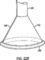
撮像フード282とその下側に位置する組織との接触を確実にする他の変形例は図22Bに見ることができる。この変形例では、撮像フード282の外周に膨張式接触端部288を有するようにすることができる。膨張式接触端部288は、撮像フード282が不均一なまたは多様な生体構造を有する組織表面上に配置されると、膨張管腔部289を通過する流体または気体で膨張させることができる。膨張した外周表面288は、組織表面と適合し、フード282内での撮像流体の保持を容易にすることで、フード端部による接触を継続することができる。
Another variation that ensures contact between the
撮像フードだけでなく、撮像および操作システムとともに各種の機器を利用することができる。例えば、撮像フード12内のフィールドから不透明な血液を一掃し、清澄液を介して下側に位置する組織を可視化した後、血液が撮像フード12内に再度滲出し観察を遮る場合がある。鮮明な撮像フィールドを自動的に維持する方法の1つでは、図23に示すように、撮像フード12内の展開カテーテルの遠位端に配置したトランスデューサー(例えば、超音速トランスデューサー290)を利用することができる。トランスデューサー290は、撮像フード12内にエネルギーパルス292を送り、撮像フード12内の堆積物または血液で反射された後方散乱エネルギー294が検出されるまで待機させることができる。後方散乱エネルギーを検出すると、自動的にポンプを作動し、堆積物または血液が検出されなくなるまで撮像フード内にさらに流体を吐出することができる。
In addition to the imaging hood, various devices can be used together with the imaging and operation system. For example, in some cases, opaque blood is swept away from the field in the
代替的に、図24Aに示すように、撮像フード12自体に1つ以上のセンサー300を配置し、多数の異なるパラメータを検出するようにしてもよい。例えば、センサー300は、周囲の血液中の酸素の存在、血液および/または撮像流体圧、撮像フード内の流体の色などについて検出を行うように構成可能である。流体の色は、反射型センサーを利用して血液からの後方反射を検出することにより撮像フード12内の血液の存在を検出する場合に特に有用であり得る。撮像フード12内に存在し得る血液からのあらゆる反射光は、展開カテーテル16を介して制御電子回路118内の赤色フィルタに光または電気伝送することができる。検出可能なあらゆる赤色光により血液の存在が示され、医師に対して信号を発するか、またはポンプを自動的に作動して撮像フード12内にさらに流体を吐出して血液を一掃することができる。
Alternatively, as shown in FIG. 24A, one or
フード12内の血液の存在を検出する代替的な方法として、撮像フード12内の撮像流体を透過する光の検出が挙げられる。例えば、LEDまたは光ファイバーを利用した白色光源を撮像フード12内で発光させる場合には、血液が存在することによって、この流体を赤色光が通過するようにすることができる。検出した赤色光の程度または強度は、撮像フード12内に存在する血液の量と対応させることができる。1つの変形例では、赤色センサー内に、単に、赤色光がどの程度検出されたかを明示可能な赤色透過フィルタを上部に有するフォトトランジスタを設けることができ、これにより、撮像フード12内の血液の存在を示すことができる。血液が検出されると、システムは、清浄流体をさらに送り込むとともに、清浄流体の圧力および流動レベルについての閉ループフィードバック制御を可能にすることができる。
An alternative method for detecting the presence of blood in the
撮像フード12の外部だけでなく、撮像フード12内のパラメータを検出するために、撮像フード12の外部302または撮像フード12の内部304に任意の数のセンサーを配置してもよい。図24Bに示すそのような構成は、図10Aおよび図10Bについて上述したように、血圧などの物理的パラメータに基づいて、鮮明な撮像フィールドを自動的に維持する際に特に有用な場合がある。
Any number of sensors may be arranged not only outside the
センサーだけでなく、1つ以上の発光ダイオード(LED)を利用して撮像フード12内に照明を当ててもよい。展開カテーテル16内を通る光ファイバーで照明を当ててもよいが、撮像フード12上にLEDを用いることにより、さらなる光ファイバーを用いて照明を当てる必要性をなくすことができる。上記1つ以上のLEDに接続した電線をフード12内に通すか、またはフード12上を外面に沿って通してもよく、あるいは、展開カテーテル16内に押し出すようにしてもよい。1つ以上のLEDを、図25Aに示すような撮像フード12の外周パターン306で、または図25Bに示すような撮像フード12に沿った直線的な縦パターン308で配置してもよい。弦巻または螺旋パターンなどの他のパターンも利用可能である。代替的に、撮像フード12を一部を形成する支持部材に沿ってLEDを配置してもよい。
Not only the sensor but also one or more light emitting diodes (LEDs) may be used to illuminate the
撮像フード12内に照明を当てるための他の代替例では、図26Aに示すように、単体の照明器具310を利用してもよい。そのような器具の例としては、柔軟性血管内送達部材312が挙げられるが、この送達部材312の遠位端には、担持部材314を枢動可能に接続316してもよい。1つ以上のLED318を担持部材314に沿って設置してもよい。使用時には、送達部材312は、担持部材314が撮像フード12内に配置されるまで展開カテーテル16を介して送るようにしてもよい。撮像フード12内に入ると、担持部材314は、任意の数の方向に枢動し、図26Bに示すように、撮像フード12内の照明を容易または最適化することができる。
In another alternative for illuminating the
照明用のLEDを利用する際には、撮像フード12または個別の機器に沿って配置されているかに関わらず、LEDは、単色のLED、例えば、白色光を含むようにしてもよい。代替的に、他の色のLED、例えば、赤、青、黄などを、単独でまたは白色LEDと組み合わせて利用し、撮像している組織または流体に対して多様な照明を行ってもよい。代替的に、赤外線または紫外線光源を使用して組織表面の下での撮像を可能にするか、またはシステムの誘導、診断、または治療に使用するために組織の蛍光化を行ってもよい。
When using an LED for illumination, the LED may include a single color LED, for example, white light, regardless of whether the LED is disposed along the
可視化プラットホームの提供だけでなく、撮像アセンブリを利用して、可視化している組織の治療のための治療プラットホームを提供することもできる。図27に示すように、展開カテーテル320は、上述したような撮像フード322を有するとともに、流体送達管腔部324および撮像管腔部326を有することができる。この変形例では、ニードル328などの治療器具を、流体送達管腔部324を介してまたは他の作用管腔部に送達することができ、可視化した組織の治療のために開口エリア332内に送ることができる。この場合、ニードル328は、薬剤を送達するための1つまたは数個のポート330を規定するようにしてもよい。よって、組織の適切な領域を撮像および確認すると、ニードル328を前進させて下側に位置する組織を貫通させ、ポート330を介して治療薬を送達することができる。代替的に、ニードル328は、下側に位置する対象組織領域を剥離するために、例えば、高周波、マイクロ波などで電源334と電気通信を行うようにしてもよい。
In addition to providing a visualization platform, an imaging assembly can also be utilized to provide a treatment platform for treatment of the tissue being visualized. As shown in FIG. 27, the
図28は、展開カテーテル340に上述のように撮像フード342を取り付けているが弦巻状組織貫通デバイス344構成の治療器具344を備えた他の代替例を示す。下側に位置する組織に対して撮像フードを安定させる際の使用について図7Aおよび図7Bに図示し上述したように、弦巻状組織貫通デバイス344を利用して、各種の治療手技のために組織を操作することも可能である。弦巻部346により、その内部を介して治療薬を送達するための1つまたは数個のポートを規定してもよい。
FIG. 28 illustrates another alternative with a
さらに他の代替例に関して、図29は、例えば、生理食塩水356を充填した拡張式撮像バルーン352を有する展開カテーテル350を示す。上述のように、治療器具344は、バルーン352に対して平行移動可能にすることができる。当該器具の貫通部346によってバルーン352が破裂しないようにするために、バルーン352上にストッパー354を形成し、部材346の近位側がストッパー354を通過しないようにしてもよい。
For yet another alternative, FIG. 29 shows a
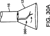
撮像フード12内での組織の操作に用いるために展開カテーテル16を介して送達可能な器具の代替構成を図30Aおよび図30Bに示す。図30Aは、展開カテーテル16を介した血管内送達のための細長軸を有するように構成され、撮像フード12内への展開時にその細長軸と角をなす遠位端を備えた組織捕捉器具などの湾曲機器360の1つの変形例を示す。細長軸は自動的に角度をつけるように構成可能であるが、例えば、細長軸を少なくとも部分的に形状記憶合金で構成するか、または操作時に、例えば、プルワイヤに張力をかけることによってそのような構成とすることができる。図30Bは、撮像フード12内において遠位部分を軸外構成に再構成するように構成された機器362の他の構成を示す。いずれの場合も、機器360、362は、展開カテーテル16内に入るように近位側に後退させる際に薄型構成に再構成することができる。
An alternative configuration of an instrument that can be delivered via the
撮像システムとともに利用可能な他の機器または器具を図31A〜図31Cの側面図および端面図に示す。図31Aは、薄型構成から曲線形状に再構成可能な遠位端部エフェクター372を有するプローブ370を示す。端部エフェクター372は、高周波エネルギー、マイクロ波エネルギー、超音波エネルギー、レーザーエネルギー、または冷凍剥離さえも利用する剥離プローブとして構成可能である。代替的に、端部エフェクター372は、下側に位置する組織を介して伝送される電気信号を検出またはマッピングするための電極をいくつか有するようにしてもよい。
Other devices or instruments that can be used with the imaging system are shown in the side and end views of FIGS. 31A-31C. FIG. 31A shows a
下側に位置する組織の剥離に利用される端部エフェクター372の場合、細長部材376上に配置した熱電温度計またはサーミスタ374などのさらなる温度センサーを、遠位端部エフェクター372に隣接させながら撮像フード12内に送り、剥離した組織と接触させるとともにその温度を監視するようにしてもよい。図31Bは、単に角度をつけることにより垂直構成となり組織と接触することが可能な遠位端部エフェクター372の1つの構成例の端面図を示す。図31Cは、組織との接点を増やすために端部エフェクターを曲線端部エフェクター378に再構成できる他の例を示す。
In the case of an
図32Aおよび図32Bは、撮像フード12とともに利用される剥離器具の底部が封止されている他の変形例を示す。この変形例では、遠位端部エフェクター382を有する冷凍剥離プローブ380などの剥離プローブを撮像フード12内を通過するように配し、図32Bの端面図に示すように、端部エフェクター382が透明膜または封止部384の遠位側に位置するようすることができる。プローブ380の軸は、膜384内に規定された開口部386を通過することができる。使用時には、上述したように、撮像フード12内に清澄液を送り込み、撮像フード12で剥離される組織領域上に遠位端部エフェクター382を置き、膜384が剥離した組織の上または隣に配置されるようにすることができる。冷凍剥離の場合には、撮像フード12内に吐出する前に撮像流体を予熱し、膜384が接触する組織が冷凍剥離術中に温められるようにしてもよい。熱剥離の場合(例えば、高周波エネルギーを利用する場合)には、撮像フード12内に吐出した流体を冷却し、剥離術中に膜384と接触するとともに剥離プローブと隣接する組織が同様に冷却されるようにしてもよい。
FIG. 32A and FIG. 32B show another modification in which the bottom of the peeling device used together with the
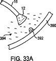
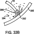
上述のいずれの例でにおいても、撮像流体の温度を変えることにより、組織に対する各種手術を容易にすることができる。他の場合では、撮像流体自体を変化させて各種処置を容易にしてもよい。例えば、図33Aに示すように、展開カテーテル16および撮像フード12を、尿394が溜まった膀胱などの中空の体器官内において膀胱壁上の病変または腫瘍392に向けて送ることができる。病変392の全体または病変の一部を覆うように撮像フード12を置いてもよい。組織壁390上に固定すると、図33Bに示すように、冷凍流体、すなわち、例えば、水または血液の氷結温度よりも低い温度に冷却した流体を撮像フード12内に送り込んで病変390を冷凍剥離しながら、機器または組織表面上に氷が生成されないようにすることができる。
In any of the above examples, various operations on the tissue can be facilitated by changing the temperature of the imaging fluid. In other cases, the imaging fluid itself may be changed to facilitate various treatments. For example, as shown in FIG. 33A, the
冷凍流体が撮像フード12から漏出して器官内に入ると、流体は患者の体によって自然に温められ、最終的には消滅させることができる。冷凍流体は、下側に位置する組織の可視化を可能にする無色かつ半透明の流体とすることができる。そのような流体の例としては、無色かつ無臭の過フッ素化液であるFluorinert(登録商標)(3M,St.Paul,MN)が挙げられる。Fluorinert(登録商標)などの液体の使用により、撮像フード12内外に氷を形成することなく冷凍剥離手術が可能になる。代替的に、冷凍剥離を利用するのではなく、Fluorinert(登録商標)液を高温まで加熱して温熱処理を行うことで撮像フード12内の病変392を剥離してもよい。さらに、心臓内など、体の他の様々な部分にFluorinert(登録商標)を利用してもよい。
As the frozen fluid leaks from the
図33Cは、本発明に係るシステムの他の変形例を示す。この変形例では、超音波ビーム598(例えば、一般にHIFUと称される高周波超音波)トランスデューサー600をフード12および/またはカテーテル16と一体化している。ビーム598は、組織内の対象領域に集中する。これにより、超音波ビームを介した組織の焼灼または溶着が可能となる。操作者がビーム598を標的組織表面上に正確に集中させるには、澄明な溶液が役立つ。任意に、ビーム598の焦点604に合致するレーザーポインター、LED、または他のポインティングデバイス/指示器602をガイドとして用いてビーム598が確実に組織表面上に正確に配置されるようにすることができる。
FIG. 33C shows another modification of the system according to the present invention. In this variation, an ultrasound beam 598 (eg, high frequency ultrasound, commonly referred to as HIFU) transducer 600 is integrated with the
この変形例の考え得る1つの用途は、二次中隔を一次中隔上に溶着して閉鎖を行うPFOの治療である。代替的に、HIFUで二次中隔に傷をつけるだけで、引き続き治癒過程が始まり一次中隔を組織で閉じることができる。 One possible use of this variant is in the treatment of PFOs where the secondary septum is welded onto the primary septum and closed. Alternatively, simply hurting the secondary septum with HIFU can continue the healing process and close the primary septum with tissue.
図34Aは、撮像システムとともに利用可能な機器の他の変形例を示す。この変形例では、レーザーリング発生器400を展開カテーテル16に通し、その一部を撮像フード12内に入れるようにすることができる。典型的には、レーザーリング発生器400を用いてレーザーエネルギーの円環402を生成し、典型的には、心房細動の治療において肺静脈の周囲に伝導ブロックを発生させる。レーザーエネルギーの円環402は、撮像している組織に直接組織剥離を行なうために、その直径が撮像フード12の直径内に納まるように発生することができる。心房細動を引き起こす信号は、典型的には、肺静脈に対する侵入エリアから左心房に入り、治療には、心房内の肺静脈口への剥離エネルギーの送達が含まれる場合がある。組織の剥離エリアには、心房細動に対する刺激を遮断する円形の傷が生じることがある。
FIG. 34A shows another modification of the device that can be used together with the imaging system. In this variation, the
レーザーエネルギーを用いて心臓の組織を剥離する場合、一般には、表面の上側に位置する組織の完全性および健康を維持しながら下側に位置する組織を剥離することが望まれる。これは、例えば、撮像流体を患者の体温よりも低いが血液の凝固点(例えば、2℃〜35℃)よりも高い温度に冷却することにより達成可能である。よって、冷却した撮像流体は表面組織を冷却した流体の温度に維持することができる一方で、より深い場所に位置する組織は患者の体温に保たれる。レーザーエネルギー(または高周波エネルギー、マイクロ波エネルギー、超音波エネルギーなどの他の種類のエネルギー)で組織を照射すると、冷却した組織表面およびより深い場所に位置する組織の両方の温度が均一に上昇する。体温に維持されたより深い場所に位置する組織は、下側に位置する組織を破壊するほど十分に高い温度になる。一方で、冷却した表面組織の温度も上昇するが、その温度は体温とほぼ同じかまたは僅かに高い程度である。 When exfoliating cardiac tissue using laser energy, it is generally desirable to exfoliate the underlying tissue while maintaining the integrity and health of the tissue located above the surface. This can be accomplished, for example, by cooling the imaging fluid to a temperature below the patient's body temperature but above the blood freezing point (eg, 2 ° C. to 35 ° C.). Thus, the cooled imaging fluid can maintain the surface tissue at the temperature of the cooled fluid, while the tissue located deeper is kept at the patient's body temperature. Irradiating tissue with laser energy (or other types of energy such as high frequency energy, microwave energy, ultrasonic energy) uniformly increases the temperature of both the cooled tissue surface and deeper tissue. Tissues located at deeper locations maintained at body temperature will be at a sufficiently high temperature to destroy the underlying tissue. On the other hand, the temperature of the cooled surface tissue also rises, but the temperature is about the same as or slightly higher than the body temperature.
従って、図34Bに示すように、治療の一例として、患者の心臓Hの心房中隔ASを経て左心房LA内に展開カテーテル16Aを通すことが挙げられる。左心房LAにアクセスする他の方法も利用可能である。撮像フード12およびレーザーリング発生器400を肺静脈PVの1つ以上の静脈口OTと隣接させるかまたはその上に配置させることができ、レーザー発生器400は、レーザーエネルギーの円環402により静脈口OTの周囲の組織を剥離して伝導ブロックを生成することができる。静脈口OTの周囲の1つ以上の組織を剥離すると、撮像フード12を薄型に再構成して患者の心臓Hから取り出すことができる。
Therefore, as shown in FIG. 34B, an example of treatment is passing the deployment catheter 16A through the atrial septum AS of the patient's heart H and into the left atrium LA. Other methods of accessing the left atrium LA are also available. The
可視化素子52がカテーテル16の端部および/またはフード12上に位置するシステム10の変形例を図34Cにも示す。デバイス10はまた、レーザー源608と結合したファイバ606も含む。ファイバ606を任意で移動させることができるため、レーザービームを所望の領域に集中して組織を治療することができる(例えば、組織の損傷は時間が経過することにより治癒する)。ファイバ606は、レーザーエネルギーを様々なパターンで方向づけることができる(例えば、局所的な治療、リング形状、様々な幾何形状など)。レーザーは、視準してもしなくてもよい(レーザービームを視準した場合には、伝播時に所与のビームサイズに対するビームの広がりを最小にすることができる)。
A variation of the
図34Dは、本発明に係るシステムの他の変形例を示す。この変形例では、膨張式部材520フード12が拡張するため、デバイス10を前進させて組織に押えつけることができる。この変形例では、フードが組織表面を適切に封止していないかまたは部分的にしか封止していない場合に生理食塩水または他の流体が過剰に使用されることを防止する。膨張式部材520は、エネルギー(例えば、線521で示すレーザーまたは超音波など)を透過するように製造することができる。例えば、膨張式部材をシリコーンで製造してもよく、部材520を膨張させるために低熱伝導率液が用いられる。
FIG. 34D shows another modification of the system according to the present invention. In this variation, the
静脈口OT内またはその周囲の組織を処置する上での問題点の1つは、静脈口OTを通過する血液の動的な流体流である。動態作用は、静脈口OTの挿管または侵入を困難にする。よって、撮像システムとともに利用可能な機器または器具の他の変形例は、図35Aに示すように、内部にカニューレ管腔部412が規定された伸張式カニューレ410である。伸張式カニューレ410は、一般に、図35Bに示すように、送達時に展開カテーテル16内に配置された後、撮像フード12を介して遠位側に突出し、任意でさらに伸張することが可能な細長管状部材を備える。
One problem in treating tissue in or around the vein OT is the dynamic fluid flow of blood through the vein OT. The kinetic action makes it difficult to intubate or penetrate the ostium OT. Thus, another variation of a device or instrument that can be used with an imaging system is an
使用時には、撮像フード12が、例えば、図35Cに示すように、肺静脈PVの静脈口OTの外側の組織に対して所望どおりに配置されると、伸張式カニューレ410が展開カテーテル16から遠位側に突出しながら、上述したように、任意で撮像フード12を介して組織を撮像することができる。伸張式カニューレ410は、その遠位端が少なくとも部分的に静脈口OT内に延びるまで遠位側に突出可能である。静脈口OT内に入ると、静脈口OT内での処置のために、機器またはエネルギー剥離デバイスをカニューレ管腔部412内から外側に延ばすことができる。処置が完了すると、カニューレ410を近位側に後退させ、患者の体内から取り出すことができる。伸張式カニューレ410はまた、PVからの血流を遮断し組織領域の鮮明な光景を維持する膨張式閉塞バルーンを遠位端にまたはその近辺に含む。代替的に、伸張式カニューレ410は、その内部から閉塞バルーンの先までの管腔部を規定し、血液がカニューレ410を介して撮像フードの近位側に出るように方向づけることにより、通常は肺静脈PVから出る血液の少なくとも一部を迂回させることができる。
In use, when the
器具または機器の用途のさらに他の変形例は、図36Aおよび図36Bの側面図および端面図に見ることができる。この変形例では、撮像フード12は、フード12と一体化した1つ以上の管状支持部材420を有するようにすることができる。各管状支持部材420は、下側に位置する組織に対する治療のために1つ以上の機器または器具を送達することができるアクセス管腔部422を規定してもよい。具体例の1つは、図7Cについて図示し上述している。
Still other variations of instrument or equipment applications can be seen in the side and end views of FIGS. 36A and 36B. In this variation, the
システムの使用またはその使用を容易にするために様々な方法および機器を利用することができる。例えば、1つの方法として、最初に行う患者の心臓内へのデバイスの送達および配置を容易にすることが挙げられる。最初に心室内の撮像アセンブリを、例えば、僧帽弁MVに誘導する際に、図37Aおよび図37Bに示すように、単体の誘導プローブ430を利用してもよい。誘導プローブ430は、例えば、光源434を用いて遠位先端部432に照明を当てることが可能な光ファイバーを備えてもよい。先端部432は、先端部が僧帽弁MVと隣接して配置されるまで、例えば、冠状静脈洞CSを介して心臓内に送ることができる。先端部432は、図37Aに示すように、発光させることができ、そして、撮像アセンブリ10を、心房室内から僧帽弁MVに向かって見ることができる発光した先端部432に向けて誘導することができる。
Various methods and equipment can be utilized to facilitate the use or use of the system. For example, one method includes facilitating delivery and placement of the device into the patient's heart for the first time. When initially guiding the intraventricular imaging assembly to, for example, the mitral valve MV, a
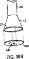
上述したデバイスおよび方法だけでなく、撮像システムを利用して他の様々な処置を容易にすることができる。ここで図38Aおよび図38Bを参照すると、このデバイスの撮像フードが特に利用可能である。この例では、折畳可能な膜または円盤形状部材440を撮像フード12の接触端部または縁部に一時的に固定することができる。血管内送達時には、撮像フード12および取り付けた部材440の両方を折畳構成にして、送達のために薄型を維持することができる。展開時には、撮像フード12および部材440の両方を延ばして拡張構成にすることができる。
In addition to the devices and methods described above, an imaging system can be utilized to facilitate various other procedures. Referring now to FIGS. 38A and 38B, the imaging hood of this device is particularly available. In this example, the foldable membrane or disk-shaped
円盤形状部材440は、用途に応じて各種の材料から構成してもよい。例えば、部材440は、医薬を下側に位置する組織内にゆっくりと注入するために組織表面に埋め込む薬剤溶出医薬442を注入した多孔質ポリマー材料で製造することができる。代替的に、創傷または空洞に対する埋め込みおよび閉鎖により流体の漏出を防ぐために、上記部材440を非多孔質材料(例えば、金属または高分子)で製造してもよい。さらに他の代替例では、部材440を、拡張状態の撮像フード12に固定する伸張性材料で作ってもよい。組織表面または創傷に埋め込みまたは固定すると、拡張した部材440を撮像フード12から取り外すことができる。取り外す際には、拡張した部材440を収縮して小型化するとともに、取り付けた下側に位置する組織に近接させて、例えば、創傷または開口部を塞ぐことができる。
The disk-shaped
円盤形状部材440を組織表面に固定する1つの方法には、部材440の表面に取り付けられる、例えば、とげ、かぎ、突起などの複数の組織アンカー444が含まれる。他の取付方法には、接着剤、縫合などが含まれる。使用時には、図39A〜図39Cに示すように、遠位側に突出する複数の組織アンカー444を備えた部材440が取り付けた拡張構成となるように撮像フード12を展開することができる。組織アンカー444を、図39Aに示すように、治療する組織領域446に対して推進し、これを、図39Bに示すように、アンカー444が組織に固定されるとともに、部材440が組織上に直接配置されるまで行うことができる。プルワイヤを作動させて撮像フード12から部材440を取り外し、展開カテーテル16を近位側に後退させ、部材440を組織446に固定したままにすることができる。
One method of securing the disk-shaped
組織の操作および処置の他の変形例は、展開式アンカーアセンブリ450が組織接触端部22に取り付けられた撮像フード12を示す図40Aの変形例に見ることができる。図40Bは、明瞭にするために、撮像フード12から外したアンカーアセンブリ450を示す。アンカーアセンブリ450が、それぞれアンカー456の近位端に縫合糸保持端(例えば、アイレットまたは開口部)458を有する複数の分離組織アンカー456(例えば、とげ、かぎ、突起など)を有する様子を見ることができる。縫合糸部材またはワイヤ452は、開口部458を介するとともに、縫合糸またはワイヤ452上を一方向に摺動して各アンカー456を相互に近接させるように構成可能な締付素子454を介して各アンカー456と摺動可能に接続することができる。各アンカー456は、各種の方法により、撮像フード12に一時的に取り付けることができる。例えば、プルワイヤまたは保持ワイヤは、撮像フード12の外周の環状受取部内に各アンカーを保持してもよい。アンカー456を取り外すと、患者の体外の近位端からプルワイヤまたは保持ワイヤに張力が掛けられ、それによって撮像フード12からアンカー456を離すことができる。
Another variation of tissue manipulation and treatment can be seen in the variation of FIG. 40A showing
開口部または創傷460(例えば、卵円孔開存(PFO))の閉鎖のためのアンカーアセンブリ450の一使用例を図41A〜図41Dに示す。展開カテーテル16および撮像フード12は、例えば、患者の心臓に経脈管的に送達可能である。撮像フード12が展開して拡張構成になると、図41Aに示すように、撮像フード12が開口部または創傷460と隣接して配置され得る。アンカーアセンブリ450が拡張した撮像フード12上に位置する状態で、図41Bに示すように、撮像フード12の接触端部およびアンカーアセンブリ450が組織開口部460の周囲の領域に推進されるように展開カテーテル16を展開することができる。アンカーアセンブリ450を周囲の組織に固定すると、図41Cに示すように、アンカーアセンブリ450および縫合糸部材452がアンカーと繋がった状態で撮像フード12からアンカーを取り外すことができる。図41Dに示すように、縫合糸またはワイヤ部材452を患者の体外から近位側に引っ張ってアンカーアセンブリ450のアンカーを相互に近接させて巾着のように締めることにより組織開口部462を閉じることができる。締付素子454はまた、縫合糸またはワイヤ部材452上で遠位側に押すことによって、近接したアンカーアセンブリ450の弛みまたは広がりを防ぐことができる。
One example use of
図41Eは、インプラント464を送達するように構成された組織撮像および操作アセンブリ10を示す。この変形例では、インプラントは、複数の血液凝固ファイバ466を有する軸を備える。インプラント464は、組織取付部材468をさらに含む。。使用時には、アセンブリ10は、インプラント464を組織エリアまたは空洞に送達する。インプラントは、取付部材468を用いて回転させることで組織内に埋め込み(または取り付け)可能である。インプラント464は、特に、空洞または開口部の閉塞が必要な場合には、本明細書に示した他の手順と組み合わせてもよい。
FIG. 41E shows the tissue imaging and
図41Fは、本発明に係るアセンブリ10の他の変形例を示す。この場合、インプラント474は、ステント、コイル、パッチ、縫合糸、または他のそのようなインプラントを備えてもよい。インプラント474は、送達カテーテル473または同様の手段を用いて送達可能である。
FIG. 41F shows another variation of the
展開カテーテル16および展開撮像フード12を患者の体内に配置して血液472を展開カテーテル16内に吸い込むことが可能な他の代替的な使用例を図42に示す。吸い込んだ血液472を患者の体外に位置する透析部470に送り込み、その吸い込んだ血液472を濾過し、濾過した血液を再度患者内に戻すようにすることができる。
FIG. 42 shows another alternative use case where the
さらに他の変形例を図43Aおよび図43Bに示すが、これらの図面には、第1の展開式フード482および第1のフード482から離れて配置された第2の展開式フード484を有する展開カテーテル480の変形例を示している。展開カテーテル480はまた、展開カテーテル480の長さ方向に沿って第1のフードおよび第2のフード482、484間に配置された側視撮像素子486を有してもよい。使用時には、そのようなデバイスを血管VSの管腔488を介して入れることができ、一方または両方フード482、484が拡張して血管VSの周囲の壁と軽く接触するようにすることができる。図43Bに示すように、フード482、484が拡張すると、フード482、484間に規定された空間に透明な撮像流体を送り込んであらゆる血液を押しのけ、撮像空間490を作ることができる。フード482、484の間に清澄液が存在するため、撮像素子486を用いてフード482、484の間に納まった周囲の組織表面を観察することができる。展開カテーテル480、およびカテーテル480に沿って規定された1つ以上の開口部に他の機器または器具を通過させて、血管壁に対する治療手技をさらに行ってもよい。
Still another variation is shown in FIGS. 43A and 43B, which show a deployment having a first
図43Cは、密接した一連の展開式フード482、484を有する展開カテーテル480の他の変形例を示す。展開カテーテル480は少なくとも2つの流体光供給部管腔部476、478を有し、各管腔部は外側482および内側484フード内の開口エリアと流体接続される。使用中には、外側および内部フード482、484間を流れる流体が内側フード484の周囲から血液、堆積物または他の障害物を一掃する。これにより開口エリアへの体液の侵入を防ぐことでデバイスが内部フード484内の可視化をより良好に行うようにできることが1つの利点である。これは、内部フード484が組織と接し、外側フード482からの流体によって内部フード484の開口エリアへの体液の侵入を妨げる流動パターンを生成する場合に特に有用である。
FIG. 43C shows another variation of the
可視化素子は、一方または両方のフード内に配置してもよい。このデバイスの1つの変形例では、内部フード484を透明材料で製造し、1つ以上の可視化素子を外側フード482内に配置してもよい。代替的に、または加えて、内部フード484の開口エリアを可視化するために可視化素子を配置してもよい。任意の数のフードを使用可能であることに留意されたい。
The visualization element may be placed in one or both hoods. In one variation of this device, the
機器の側方の組織の撮像に使用可能な展開カテーテル500の他の変形例を図44A〜図45Bに見ることができる。図44Aおよび図44Bは、膨張していない薄型構成の側方撮像バルーン502を有する展開カテーテル500の側面図および端面図を示す。バルーン502が配置されたカテーテル500の遠位部分に側方撮像素子504を配置することができる。バルーン502が膨張すると、半径方向に拡張して周囲の組織と接触するが、撮像素子504が位置する場所では、図45A〜図45Bの側面図、上面図、および端面図のそれぞれに示すように、バルーン502によって可視化フィールド506を作ることができる。可視化フィールド506は、可視化素子504が鮮明かつバルーン502によって邪魔されないフィールド506内の領域の画像を提供されるように膨張したバルーン502内に規定された単なる空洞またはチャネルである。
Other variations of the
使用時には、血管管腔488を介して可視化または治療する病変または腫瘍508に向けて経脈管的に展開カテーテル500を送ることができる。病変508に到達すると、展開カテーテル500は病変508と隣接して配置され、病変508が可視化フィールド506内に納まるようにバルーン502を膨張させることができる。バルーン502が完全に膨張して血管壁と接触すると、図46Aおよび図46Bの側面図および端面図のそれぞれに示すように、展開カテーテル500を介して可視化フィールド506内に清澄液を送り込み、フィールド506内からあらゆる血液または不透明な流体を押しのける。そして、任意の数の機器を展開カテーテル500を介してフィールド506内に入れることにより、病変508を外観検査して治療することができる。
In use, the
図47A〜図47Bは、システム560の構成要素が組織の切開/鈍的切開を可能にする本発明によるデバイスの変形例を示す。図示するように、フード564は、フード564が複数の剛体部品566または葉状部を備えるカテーテル562から延在する。葉状部566、568、570は、硬質金属または高分子から製造可能である。さらに、このデバイスの変形例には、交代性構成(例えば、硬質葉状部間に柔軟葉状部が配置され、硬質または固い葉状部の間に柔軟な葉状部が配置されるなど)を有する葉状部566、568、570を含んでもよい。葉状部はデバイス560の先端572に向かって先細りする形状を有するように示されているが、デバイスの先端572は、組織に対する不要な外傷を回避するために十分に鈍角化していてもよい。
47A-47B show a variation of the device according to the present invention in which the components of
図47Aは、デバイス560が隣接する組織層2、4に近づく様子を示す。図47Bに示すように、適切に配置されると、デバイス560は、開いたり、開閉を繰り返すことにより組織層2、4を分離して組織を切開する。図47Bはまた、切開フード564が隣接する葉状部566、568、570間に位置する柔軟材料またはウェビング576を有する様子も示している。この柔軟材料/ウェビング576は、フードが組織表面と隣接するように置かれると、フードがシーリングを形成できるようにする。図示するように、葉状部566、568、570は(重複部分569で示すように)重なり合うようにすることができる。
FIG. 47A shows the
図48Aは、細長バイパス部580をさらに含む組織撮像および操作アセンブリ10の変形例を示す。細長バイパス部580は、カテーテル16の近位側開口部584とフード16の遠位側に位置する遠位側開口部586との間に流体経路を可能にする少なくとも1つのバイパス管腔部582を含む。バイパス管腔部582は、外科処置時に、流体が開口エリアを迂回して通過することを可能にする。さらに、フード12は、開口エリアの可視化を可能にする1つ以上の可視化素子52を含んでもよい。アセンブリ10の変形例には、流体がアセンブリ10内を移動する際に役立つポンプ型デバイス578を含むことができる。
FIG. 48A shows a variation of the tissue imaging and
細長バイパス部580は、フード12またはカテーテル16に対して移動可能であってもよい。また、細長バイパス部580は、各種の処置を容易にする1つ以上の構造を含んでもよい。例えば、図48Bは、図48Aのシステム10に支持フラップ588を追加した変形例を示す。支持フラップ588は、送達のためにフラップ588の形状を小型化することできる材料で製造することが好ましい。拡張時に組織上に配置されと、フラップ588は半剛体的に支持を行う。この構成の1つの用途では、アセンブリ10を弁(例えば、僧帽弁)に通して、フード12が当該弁の上側に第1の開口エリアを作るようにすることができる。次いで、フラップ588が弁の遠位側表面を支持するようにしてもよい。従って、カテーテル16を介して開口エリア内に向かってデバイスを送り、弁の外科的修復を行うことができる。さらなる変形例では、カテーテル586の近位側開口部584と遠位端の間の領域に弁(例えば、一方向弁)を備えて流体の流動を制御する、(一方向弁の場合、流体は単一方向にのみ流動する)。
The
図48Cは、組織(または弁)の遠位側表面上に配置されたフラップ588の断面図を示す。図示するように、フード16が組織の上側に開口エリアを作ることによって、組織を修復または治療するためにカテーテル16内にデバイス592を送ることができる。上記でし示したように、細長部580をカテーテル16に対して後退させて、フード12とフラップ588の間の組織を固定することができる。図48Cはまた、細長部580が組織取付部材590をさらに含むアセンブリ10の変形例を示す。この変形例では、組織取付部材590は弦巻状部材を備える。
FIG. 48C shows a cross-sectional view of the
図48Dは、拡張したフード12がカテーテル16の中心からずれている本発明に係るアセンブリ10の変形例を示す。この変形例は、細長部580も拡張時のフード12の中心からずれているアセンブリを含む。可視化素子52をフード12の一方の側に配置して開口エリアの観察を最適化できるようにすることができる。しかしながら、本発明はまた、開口エリア内の任意の場所および任意の構造上に1つ以上の可視化素子を配置することも企図する。図48Dに示すようなフードが偏った構成のアセンブリの変形例に、図48A〜図48Cに示すような支持フラップを組み込む場合および組み込まない場合も考えられる。
FIG. 48D shows a variation of the
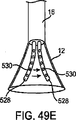
図48Eは、細長部580を有するアセンブリ10の他の変形例を示す。この変形例では、細長部580は、最終的にカテーテル16を介して排出される流体を供給する。図示するように、流体が細長部580を介して標的部位に入ると、フード12は、流体が開口エリアを通過して漏れないようにする。開口エリアと流体連絡する管腔部は流体を排出し、また、左心耳LAAに位置する血液を吸引することもできる。そのような変形例は、左心耳LAAでの作業に有用である。アセンブリ10の変形例には、アセンブリ10を標的部位において安定させる組織取付部材590を含んでもよい。使用時には、このデバイスは、心臓壁を介して右心房RA内を通過し、左心房LA内の左心耳LAA内に入る。組織取付部材590を回転させて組織内に入れることにより、フード12および細長部材580を心耳LAA内で固定することができる。上記のように、細長部材580は、カテーテル16およびフード12に対して移動可能にすることができる。従って、組織取付部材590が組織と結合した際に細長部材580を引くことにより、フード12と心耳LAAの開口部の間での圧縮力の生成を助長することが可能である。
FIG. 48E shows another variation of
図48Fは、組織撮像および操作アセンブリ10の他の変形例を示す。この変形例では、アセンブリ10は、バルーン594がバルーン管腔部596と結合した細長部材580を含む。バルーン594は閉塞バルーンとして機能することができる。このようにして、ガイドワイヤまたは他の誘導手段が通過できるように細長部材580を構成してもよい。細長部580はまた、図48Aに示すようなバイパス管腔部を有することで、流体がフード12の近位側のエリアからバルーンの遠位側のエリアに移動できるように構成することもできる。
FIG. 48F shows another variation of tissue imaging and
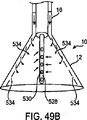
図49A〜図49Eは、複数の開口部530を有する細長部材528の使用を示す。図49Aは、カテーテル16とフード12の開口エリアの間に流体を循環させる洗浄器/吸引器として作用する細長部材528および開口部530を示す。細長部材の遠位端には、本明細書で示したように、組織取付部材を取り付けることができる。さらに、カテーテルは、流体の層流を促進する流動分配器532を有するようにすることができる。図示していないが、上述のシステムのいずれかにおいてポンプを用いて細長部材528またはカテーテル16がフード12の開口エリアから流体を吸引するようにしてもよい。アセンブリ10の変形例では、細長部材528がカテーテルの内外を移動できるようにしてもよい。本明細書に示した変形例のいずれにおいても、流体の流動は図示したものと逆にすることが可能であることに留意されたい。そのような場合には、フードまたは他の構造に、あらゆる真空力に対処するための僅かな構造的変更を必要とすることがある。
49A-49E illustrate the use of an
図49Bは、アセンブリ10の他の変形例を示す。この変形例では、フード12は、内部層に複数の開口部534を有する二重層を備える。従って、流体は、カテーテル16からフード12内に入り、開口部534から出て行く。また、細長部材528は、フード12の開口エリア内から流体を吸い込む。図49Cは、49Bと同様のアセンブリを示す。しかしながら、この変形例では、フード12の開口エリア内に流体を供給する開口部534がフード12の底に備えられる。流体はカテーテル16を介して還流する。
FIG. 49B shows another variation of the
図49Dは、本発明によるフード12の他の変形例を示す。この変形例では、フード12は、各々が流体の循環を可能にする開口部530を有する複数の細長部材528を含む。細長部材528のうちの1つ以上がフードの表面に取り付けられ一方で、1つの細長部材528がカテーテル16を介して延在する。図49Eは、2つの細長部材528がフードに取り付けられることなく、カテーテル16を介して延在する同様の変形例を示す。
FIG. 49D shows another modification of the
図50A〜図50Cは、体内に挿入されると組織表面上を平行移動または「歩行」するように設計された組織撮像および操作アセンブリ10の変形例を示す。第1の変形例では、アセンブリ10は、少なくとも1つの運動度を可能にする関節運動部または結合部538を有する外側シース536を含む。アセンブリ10は、矢印540で示すように、シース536に対して軸運動可能なカテーテル16をさらに含む。カテーテル16は、矢印544で示すように、フード12の角回転を可能にする第2の結合部542をさらに含んでもよい。従って、アセンブリ10の結合部により、組織上を通過または歩行する際に、フード12の配置換えを行うことができる。
50A-50C illustrate a variation of the tissue imaging and
図50Bは、組織表面上を平行移動または「歩行」するように設計された組織撮像および操作アセンブリ10の他の変形例を示す。この変形例では、1つ以上の「指」546、548がフード12内に移動可能に配置される。各指546、548は、矢印550で示すフード12に対する軸移動、および矢印552で示すフード12に対する角度移動を行うように設計される。従って、一方の指がフード12を越えて延びると、図50Cに示すように、指548が組織表面から離れるようにその指を持ち上げる。その第2の指546は、組織から離れるように持ち上げられると、所望の方向に進み、第1の指548が引っ込むと、伸張して組織と接触する。よって、この指の歩行運動により、組織上でフードを正確に移動させることができる。
FIG. 50B illustrates another variation of tissue imaging and
移動を開始および制御するためのユーザ制御機構は例示していないが、医療施術者によって従来から用いられる制御機構と同様のものとすることができる。代替的に、アセンブリ10を上述のようなロボット操作システムと結合してもよい。
A user control mechanism for initiating and controlling movement is not illustrated, but can be similar to a control mechanism conventionally used by medical practitioners. Alternatively, the
上記で開示した発明の用途は特定の治療または特定の体の領域に限定されるものではなく、他の任意の数の治療および体の領域を含むものである。本発明を実施するための上述の方法およびデバイスの変更、ならびに当業者に明白な本発明の局面の変形例は、本開示の範囲内であるものとする。さらに、実施例間における各種の局面の組み合わせも企図されるが、同様に本開示の範囲内にあるものとみなす。 The use of the invention disclosed above is not limited to a particular treatment or a particular body area, but includes any other number of treatments and body areas. Variations of the above-described methods and devices for practicing the invention, as well as variations of aspects of the invention that are apparent to those skilled in the art, are intended to be within the scope of the disclosure. Further, combinations of various aspects between the examples are contemplated but are considered to be within the scope of this disclosure as well.
Claims (20)
展開カテーテルから遠位側に突出するフードであって、該フードは、シース内での収縮状態からシース外での非収縮状態に該フードが再構成するように、該シースに対して平行移動するように構成されており、そして該フードは、該撮像される組織領域上にまたはそれと隣接して配置され得る開口部を規定する、フードと、
該開口部は該組織の領域に対して維持されながら、不透明流体が該フードから押しのけられて、該フード外の環境へ該開口部を通ってパージされるように、該展開カテーテルを介して該フード内に半透明流体を推進するための手段と、
可視化素子によって該半透明流体を通じて該組織領域を可視化するための手段であって、該可視化素子は、該素子が該開口部を通じて該環境と流体連絡するように、該フードによって規定される開口エリア内にまたはそれに隣接して該フード上に配置され、そして該可視化素子は、該収縮状態での該展開カテーテルの軸と一致した状態から、該非収縮状態での該展開カテーテルの長手軸に対して軸外の位置に移動される、可視化するための手段と、
を含む、システム。A system for imaging a buried region of a tissue,
A hood protruding distally from the deployment catheter, the hood being translated relative to the sheath such that the hood reconfigures from a contracted state within the sheath to a non-contracted state outside the sheath A hood that defines an opening that can be disposed on or adjacent to the tissue region to be imaged; and
The opening is maintained through the deployment catheter so that opaque fluid is pushed away from the hood and purged through the opening to the environment outside the hood while the opening is maintained against the region of tissue. Means for propelling the translucent fluid in the hood;
Means for visualizing the tissue region through the translucent fluid by a visualization element, the visualization element being an open area defined by the hood such that the element is in fluid communication with the environment through the opening. Placed on or adjacent to the hood, and the visualization element is aligned with the axis of the deployment catheter in the deflated state and from the longitudinal axis of the deployment catheter in the uncontracted state Means for visualization, moved to an off-axis position;
Including the system.
Applications Claiming Priority (3)
| Application Number | Priority Date | Filing Date | Title |
|---|---|---|---|
| US78349406P | 2006-03-17 | 2006-03-17 | |
| US60/783,494 | 2006-03-17 | ||
| PCT/US2007/064195 WO2007109554A2 (en) | 2006-03-17 | 2007-03-16 | Tissue visualization and manipulation systems |
Publications (3)
| Publication Number | Publication Date |
|---|---|
| JP2009531081A JP2009531081A (en) | 2009-09-03 |
| JP2009531081A5 JP2009531081A5 (en) | 2011-05-19 |
| JP4828633B2 true JP4828633B2 (en) | 2011-11-30 |
Family
ID=38523194
Family Applications (1)
| Application Number | Title | Priority Date | Filing Date |
|---|---|---|---|
| JP2009500630A Active JP4828633B2 (en) | 2006-03-17 | 2007-03-16 | Organization visualization and operation system |
Country Status (3)
| Country | Link |
|---|---|
| EP (1) | EP1996065A4 (en) |
| JP (1) | JP4828633B2 (en) |
| WO (1) | WO2007109554A2 (en) |
Families Citing this family (20)
| Publication number | Priority date | Publication date | Assignee | Title |
|---|---|---|---|---|
| US20110309241A1 (en) * | 2009-02-12 | 2011-12-22 | Koninklijke Philips Electronics N.V. | Interventional instrument with illumination means |
| JP2010187744A (en) * | 2009-02-16 | 2010-09-02 | Hoya Corp | Endoscopic accessory and endoscope |
| JP5267999B2 (en) * | 2009-10-26 | 2013-08-21 | 国立大学法人金沢大学 | Angioscopy system |
| WO2012051292A1 (en) * | 2010-10-13 | 2012-04-19 | Ethicon Endo-Surgery, Inc. | Methods and devices for mechanical space creation at a surgical site |
| US8603078B2 (en) | 2010-10-13 | 2013-12-10 | Ethicon Endo-Surgery, Inc. | Methods and devices for guiding and supporting surgical instruments |
| JP2012223443A (en) * | 2011-04-21 | 2012-11-15 | Olympus Corp | Guide sheath |
| JP5754630B2 (en) * | 2011-05-24 | 2015-07-29 | オリンパス株式会社 | Endoscope hood |
| FR2977135B1 (en) * | 2011-06-29 | 2014-10-10 | Univ Paris Curie | ENDOSCOPIC INSTRUMENT WITH SUPPORT FOOT |
| ES2727868T3 (en) | 2011-09-22 | 2019-10-21 | Univ George Washington | Systems for visualizing ablated tissue |
| CN104066368B (en) | 2011-09-22 | 2017-02-22 | 乔治华盛顿大学 | Systems and methods for visualizing ablated tissue |
| JP5975257B2 (en) * | 2012-03-08 | 2016-08-23 | 国立大学法人 香川大学 | Area securing instrument and endoscope provided with area securing instrument |
| WO2015073871A2 (en) | 2013-11-14 | 2015-05-21 | The George Washington University | Systems and methods for determining lesion depth using fluorescence imaging |
| EP3071095A4 (en) | 2013-11-20 | 2017-07-26 | The George Washington University | Systems and methods for hyperspectral analysis of cardiac tissue |
| JP6315379B2 (en) * | 2014-05-23 | 2018-04-25 | 株式会社トップ | Endoscope hood |
| KR102612185B1 (en) | 2014-11-03 | 2023-12-08 | 460메디컬, 인크. | Systems and methods for assessment of contact quality |
| EP3215002B1 (en) | 2014-11-03 | 2024-03-20 | The George Washington University | Systems for lesion assessment |
| JP6401098B2 (en) * | 2015-03-30 | 2018-10-03 | 富士フイルム株式会社 | Endoscopic diagnosis apparatus and operation method of endoscopic diagnosis apparatus |
| US10779904B2 (en) | 2015-07-19 | 2020-09-22 | 460Medical, Inc. | Systems and methods for lesion formation and assessment |
| WO2017203582A1 (en) * | 2016-05-23 | 2017-11-30 | オリンパス株式会社 | Endoscope-use device, and endoscopic system |
| EP4087511A4 (en) | 2020-01-08 | 2024-02-14 | 460Medical, Inc. | Systems and methods for optical interrogation of ablation lesions |
Citations (8)
| Publication number | Priority date | Publication date | Assignee | Title |
|---|---|---|---|---|
| JPS59181315A (en) * | 1983-03-31 | 1984-10-15 | Kiyoshi Inoue | Fiber scope |
| JPS6068865A (en) * | 1983-09-26 | 1985-04-19 | 住友電気工業株式会社 | Catheter |
| JPS60129055A (en) * | 1983-12-16 | 1985-07-10 | 井上 清 | Thrombus dissolving catheter |
| US4619247A (en) * | 1983-03-31 | 1986-10-28 | Sumitomo Electric Industries, Ltd. | Catheter |
| JPH01221133A (en) * | 1987-01-28 | 1989-09-04 | Robert A Mackin | Blood vessel microscope |
| JPH02130601A (en) * | 1988-11-11 | 1990-05-18 | Hitachi Ltd | Equipment protecting unit |
| JP2001258822A (en) * | 2000-03-14 | 2001-09-25 | Olympus Optical Co Ltd | Endoscope |
| US6979290B2 (en) * | 2002-05-30 | 2005-12-27 | The Board Of Trustees Of The Leland Stanford Junior University | Apparatus and methods for coronary sinus access |
Family Cites Families (6)
| Publication number | Priority date | Publication date | Assignee | Title |
|---|---|---|---|---|
| US4976710A (en) * | 1987-01-28 | 1990-12-11 | Mackin Robert A | Working well balloon method |
| CA2165829A1 (en) * | 1993-07-01 | 1995-01-19 | John E. Abele | Imaging, electrical potential sensing, and ablation catheters |
| US5908445A (en) * | 1996-10-28 | 1999-06-01 | Ep Technologies, Inc. | Systems for visualizing interior tissue regions including an actuator to move imaging element |
| US6755811B1 (en) | 1999-08-25 | 2004-06-29 | Corazon Technologies, Inc. | Methods and devices for reducing the mineral content of a region of non-intimal vascular tissue |
| US7534204B2 (en) * | 2003-09-03 | 2009-05-19 | Guided Delivery Systems, Inc. | Cardiac visualization devices and methods |
| US7860555B2 (en) * | 2005-02-02 | 2010-12-28 | Voyage Medical, Inc. | Tissue visualization and manipulation system |
-
2007
- 2007-03-16 JP JP2009500630A patent/JP4828633B2/en active Active
- 2007-03-16 EP EP07758716A patent/EP1996065A4/en not_active Withdrawn
- 2007-03-16 WO PCT/US2007/064195 patent/WO2007109554A2/en active Application Filing
Patent Citations (8)
| Publication number | Priority date | Publication date | Assignee | Title |
|---|---|---|---|---|
| JPS59181315A (en) * | 1983-03-31 | 1984-10-15 | Kiyoshi Inoue | Fiber scope |
| US4619247A (en) * | 1983-03-31 | 1986-10-28 | Sumitomo Electric Industries, Ltd. | Catheter |
| JPS6068865A (en) * | 1983-09-26 | 1985-04-19 | 住友電気工業株式会社 | Catheter |
| JPS60129055A (en) * | 1983-12-16 | 1985-07-10 | 井上 清 | Thrombus dissolving catheter |
| JPH01221133A (en) * | 1987-01-28 | 1989-09-04 | Robert A Mackin | Blood vessel microscope |
| JPH02130601A (en) * | 1988-11-11 | 1990-05-18 | Hitachi Ltd | Equipment protecting unit |
| JP2001258822A (en) * | 2000-03-14 | 2001-09-25 | Olympus Optical Co Ltd | Endoscope |
| US6979290B2 (en) * | 2002-05-30 | 2005-12-27 | The Board Of Trustees Of The Leland Stanford Junior University | Apparatus and methods for coronary sinus access |
Also Published As
| Publication number | Publication date |
|---|---|
| JP2009531081A (en) | 2009-09-03 |
| WO2007109554A2 (en) | 2007-09-27 |
| WO2007109554A3 (en) | 2008-03-06 |
| EP1996065A4 (en) | 2011-03-30 |
| EP1996065A2 (en) | 2008-12-03 |
Similar Documents
| Publication | Publication Date | Title |
|---|---|---|
| JP4828633B2 (en) | Organization visualization and operation system | |
| US20240032776A1 (en) | Precision control systems for tissue visualization and manipulation assemblies | |
| US7918787B2 (en) | Tissue visualization and manipulation systems | |
| US20220338712A1 (en) | Methods and apparatus for treatment of atrial fibrillation | |
| US11337594B2 (en) | Coronary sinus cannulation | |
| JP4769256B2 (en) | Organization visualization and manipulation system | |
| US11478152B2 (en) | Electrophysiology mapping and visualization system | |
| US10278588B2 (en) | Electrophysiology mapping and visualization system | |
| US8221310B2 (en) | Tissue visualization device and method variations | |
| US8050746B2 (en) | Tissue visualization device and method variations | |
| JP2008528239A5 (en) | ||
| JP2009543607A (en) | Method and apparatus for the treatment of atrial fibrillation |
Legal Events
| Date | Code | Title | Description |
|---|---|---|---|
| A521 | Request for written amendment filed |
Free format text: JAPANESE INTERMEDIATE CODE: A523 Effective date: 20100315 |
|
| A621 | Written request for application examination |
Free format text: JAPANESE INTERMEDIATE CODE: A621 Effective date: 20100315 |
|
| A521 | Request for written amendment filed |
Free format text: JAPANESE INTERMEDIATE CODE: A523 Effective date: 20110315 |
|
| A521 | Request for written amendment filed |
Free format text: JAPANESE INTERMEDIATE CODE: A523 Effective date: 20110331 |
|
| A871 | Explanation of circumstances concerning accelerated examination |
Free format text: JAPANESE INTERMEDIATE CODE: A871 Effective date: 20110331 |
|
| A131 | Notification of reasons for refusal |
Free format text: JAPANESE INTERMEDIATE CODE: A131 Effective date: 20110427 |
|
| A975 | Report on accelerated examination |
Free format text: JAPANESE INTERMEDIATE CODE: A971005 Effective date: 20110425 |
|
| A521 | Request for written amendment filed |
Free format text: JAPANESE INTERMEDIATE CODE: A523 Effective date: 20110726 |
|
| TRDD | Decision of grant or rejection written | ||
| A01 | Written decision to grant a patent or to grant a registration (utility model) |
Free format text: JAPANESE INTERMEDIATE CODE: A01 Effective date: 20110829 |
|
| A01 | Written decision to grant a patent or to grant a registration (utility model) |
Free format text: JAPANESE INTERMEDIATE CODE: A01 |
|
| A61 | First payment of annual fees (during grant procedure) |
Free format text: JAPANESE INTERMEDIATE CODE: A61 Effective date: 20110914 |
|
| FPAY | Renewal fee payment (event date is renewal date of database) |
Free format text: PAYMENT UNTIL: 20140922 Year of fee payment: 3 |
|
| R150 | Certificate of patent or registration of utility model |
Ref document number: 4828633 Country of ref document: JP Free format text: JAPANESE INTERMEDIATE CODE: R150 Free format text: JAPANESE INTERMEDIATE CODE: R150 |
|
| R250 | Receipt of annual fees |
Free format text: JAPANESE INTERMEDIATE CODE: R250 |
|
| R250 | Receipt of annual fees |
Free format text: JAPANESE INTERMEDIATE CODE: R250 |
|
| R250 | Receipt of annual fees |
Free format text: JAPANESE INTERMEDIATE CODE: R250 |
|
| R250 | Receipt of annual fees |
Free format text: JAPANESE INTERMEDIATE CODE: R250 |
|
| R250 | Receipt of annual fees |
Free format text: JAPANESE INTERMEDIATE CODE: R250 |
|
| R250 | Receipt of annual fees |
Free format text: JAPANESE INTERMEDIATE CODE: R250 |
|
| R250 | Receipt of annual fees |
Free format text: JAPANESE INTERMEDIATE CODE: R250 |
|
| R250 | Receipt of annual fees |
Free format text: JAPANESE INTERMEDIATE CODE: R250 |
|
| R250 | Receipt of annual fees |
Free format text: JAPANESE INTERMEDIATE CODE: R250 |
|
| R250 | Receipt of annual fees |
Free format text: JAPANESE INTERMEDIATE CODE: R250 |