JP4823468B2 - Row-diagonal parity technology that enables efficient recovery from double failures in storage arrays - Google Patents
Row-diagonal parity technology that enables efficient recovery from double failures in storage arrays Download PDFInfo
- Publication number
- JP4823468B2 JP4823468B2 JP2002379362A JP2002379362A JP4823468B2 JP 4823468 B2 JP4823468 B2 JP 4823468B2 JP 2002379362 A JP2002379362 A JP 2002379362A JP 2002379362 A JP2002379362 A JP 2002379362A JP 4823468 B2 JP4823468 B2 JP 4823468B2
- Authority
- JP
- Japan
- Prior art keywords
- parity
- diagonal
- blocks
- storage device
- data
- Prior art date
- Legal status (The legal status is an assumption and is not a legal conclusion. Google has not performed a legal analysis and makes no representation as to the accuracy of the status listed.)
- Expired - Fee Related
Links
Images


Classifications
-
- G—PHYSICS
- G06—COMPUTING; CALCULATING OR COUNTING
- G06F—ELECTRIC DIGITAL DATA PROCESSING
- G06F11/00—Error detection; Error correction; Monitoring
- G06F11/07—Responding to the occurrence of a fault, e.g. fault tolerance
- G06F11/08—Error detection or correction by redundancy in data representation, e.g. by using checking codes
- G06F11/10—Adding special bits or symbols to the coded information, e.g. parity check, casting out 9's or 11's
- G06F11/1076—Parity data used in redundant arrays of independent storages, e.g. in RAID systems
Abstract
Description
【0001】
【発明の属する技術分野】
本発明はストレージシステムのアレイに関し、詳しくは、スレージアレイ中の任意の1台の故障した記憶装置、または、任意の2台の故障した記憶装置の組み合わせを効率よく復元するための技術に関するものである。
【0002】
【従来の技術】
ストレージシステムは通常1以上の記憶装置を含み、要求に応じてそれらの記憶装置にデータを入力したりそれらの記憶装置からデータを取得したりすることができる。ストレージシステムは、限定はしないが、ネットワークに取り付けられたストレージ環境、ストレージエリアネットワーク、及び、クライアントまたはホストコンピュータに直接取り付けられたディスクアセンブリを含む、様々なストレージアーキテクチャに従って実施される。記憶装置は典型的にはディスクドライブであり、ここで「ディスク」という用語は一般に独立型の回転式磁気媒体記憶装置を意味している。この文脈での用語「ディスク」は、ハードディスクドライブ(HDD)やダイレクトアクセス記憶装置(DASD)と同義である。
【0003】
ストレージシステム内のディスクは通常、1以上のグループに編成され、各グループがRAID(Redundant Array of Independent(or Inexpensive) Disks)として運用されている。大半のRAID実施形態は、RAIDグループ内の所定数の物理ディスクに「ストライプ状」にまたがるデータの冗長書き込み、及び、そのストライプ状になったデータに関する冗長情報の適切な記憶により、データ記憶の信頼性/完全性を向上させている。この冗長情報によって、記憶装置が故障したときのデータロストの復旧が可能になる。
【0004】
ディスクアレイを運用する場合、ディスクが故障し得ることを考慮している。高性能ストレージシステムの目標は、MTTDL(Mean time to data loss)を可能な限り長くすることであり、システムの推定サービス寿命よりも長くすることが好ましい。1以上のディスクが故障した場合、データがロストする可能性があり、その装置からデータを復旧させることは不可能になる。データの損失を回避する一般的な手段としては、ミラーリング、バックアップ、パリティ保護が挙げられる。ミラーリングは、ディスク等のストレージリソースの消費という観点からは、高価な解決方法である。バックアップは、バックアップが作成された後に変更されたデータを保護することができない。パリティ手段は、わずか1台のディスクドライブをシステムに追加するだけでデータの冗長符号化を提供し、単一削除(1台のディスクの損失)を許容するので、一般的である。
【0005】
パリティ保護は、ディスク等の記憶装置上のデータの損失を防止するためにコンピュータシステムで用いられる。パリティ値は、異なるデータを有する多数の同様のディスクにわたって、あるワードサイズ(通常1ビット)のデータを足し合わせる(通常モジュロ2で)ことにより計算される。すなわち、パリティは、各々のディスク上の対応する位置にあるビットから構成される1ビット幅のベクトルに対して計算される。1ビット幅のベクトルに対して計算される場合、パリティは、合計として計算される場合と、その補数として計算される場合とがあり、これらはそれぞれ偶数パリティ、奇数パリティと呼ばれる。1ビットベクトルに対する加算および減算は、いずれも排他的論理和(XOR)演算と同じである。そして、データは、ディスクのうちのいずれか1つの損失、またはディスクのうちのいずれか1つの任意の部分のデータの損失から保護される。パリティを記憶しているディスクが失われた場合、パリティはデータから再生成することができる。データディスクのうちの1つが失われた場合、そのデータは、残ったディスクの内容を加え合わせてその結果を記憶されているパリティから減算することにより再生成することができる。
【0006】
通常、ディスクはパリティグループに分割され、パリティグループの各々が1以上のデータディスクと1つのパリティディスクとを含んでいる。パリティ集合は複数のデータブロックと1つのパリティブロックとを含むブロックの集合であり、ここでパリティブロックはそれらのデータブロックすべてのXORをとったものである。パリティグループは、1以上のパリティ集合を選択する元になるディスクの集合である。ディスク空間はストライプに分割され、各ストライプが各ディスクの中から1ブロックを保持している。あるストライプのブロックは通常、パリティグループ内の各ディスク上で同じ位置に存在する。ストライプ内では、1ブロックを除くすべてのブロックがデータを保持するブロック(「データブロック」)であり、1ブロックはそれらのデータ全てのXORをとることによって計算されたパリティを保持するブロック(「パリティブロック」)である。これらのパリティブロックをすべて1つのディスク上に記憶し、すべてのパリティ情報(かつパリティ情報のみ)を保持する1つのディスクを設けた場合、RAID−4実施形態になる。それらのパリティブロックを各ストライプの異なるディスク内に保持する場合、たいていは循環パターンが用いられ、実施形態はRAID−5になる。用語「RAID」及びその実施形態は広く知られており、1998年6月、データの管理に対する国際会議(SIGMOD)の議事録で、D.A.Patterson、G.A.Gibson、およびR.H.Katzによる「A Case for Redundant Arrays of Inexpensive Disks(RAID)」に開示されている。
【0007】
本明細書で用いられる場合、「符号化」という用語はデータブロックのうちの所定のサブセットにわたる冗長性値の計算を意味しているのに対して、「復号化」という用語は、データブロックのサブセット及び冗長性値を用いた冗長性計算の際のその同じプロセスによるデータブロックまたはパリティブロックの復元を意味している。パリティグループ内で1台のディスクが故障した場合、そのディスクの内容は、残ったデータブロックのすべての内容を加え合わせ、その結果をパリティブロックから減算することにより、予備ディスク上に復号(復元)することができる。1ビットフィールド上での2の補数加算及び減算はいずれもXOR演算と等しいので、この復元は、すべての生き残ったデータブロック及びパリティブロックのXORから構成される。同様に、パリティディスクが失われた場合も、パリティディスクは生き残ったデータから同じ方法で再計算することができる。
【0008】
パリティ手段は、一般にパリティグループ内の1つの故障に対する保護を提供するものである。これらの手段は、故障が異なるパリティグループ内で発生する限りは、複数のディスク故障に対する保護を提供することも可能である。しかしながら、パリティグループ内で2台のディスクが同時に故障した場合、復元不能なデータの損失をこうむる。パリティグループ内で2台のディスクが同時の故障することはかなり一般的に起こりうるものであり、特にその原因は、ディスクの磨耗、及び、ディスクの動作に関する環境要因である。この文脈で、パリティグループ内での2台のディスクの同時の故障は「2重故障」と呼ばれる。
【0009】
2重故障は、典型的には、1台のディスクの故障と、その最初の故障からの復旧を試みている間に生じた他のディスクの故障の結果として発生する。復旧時間または復元時間は、ストレージシステムのアクティビティのレベルに依存している。すなわち、故障したディスクを復元している間、ストレージシステムは「オンライン」のままであり、データに対するアクセス(読み出し及び/又は書き込み)の要求(クライアントまたはユーザからの)に関するサービスを提供することが可能である。ストレージシステムが要求に対するサービスの提供に忙しい場合、復元の所要時間は増加することになる。失われたデータを復元するためには生き残ったディスクのすべてを読み出す必要があるので、この復元処理時間はストレージシステムのディスクの数やサイズが増加するのに応じても増加する。また、2重故障確率は、パリティグループ内のディスク数の2乗に比例する。しかしながら、パリティグループを小さくすることは、各パリティグループが冗長データを扱うために1ディスク全体を必要とするので、費用がかかることになる。
【0010】
ディスクの他の故障形態は、ディスク内の1ブロックまたは1セクタが読み出せなくなるというメディア読み込みエラーである。ストレージアレイにパリティが保持されていれば、その読み出し不能なデータを復元することができる。しかしながら、あるディスクがすでに故障しているときに、アレイ内の他のディスクに対して読み出しエラーが起きると、データが失われる。これが2重故障の第2の形態である。
【0011】
従って、2重故障に対して耐性のある技術を提供することが望まれている。この技術は、より大きなパリティグループを有するより大きなディスクシステムの構成を可能にする一方、一台のディスク故障に長い時間(例えば数時間)を要した後の復元であっても、システムが2重故障に耐えることを保証する。このような技術により、ストレージシステムに対する特定の設計上の制限を緩和することができる。例えば、ストレージシステムはより低コストのディスクを使用し、かつ、それでも高いMTTDLを維持することができるようになるであろう。低コストのディスクは高コストのディスクに比べて一般に寿命が短く、寿命までの間に故障する確率も高い。従って、ストレージシステムがパリティグループ内の2重ディスク故障に耐えることができれば、このようなディスクの使用がもっと可能になる。
【0012】
2重故障を訂正するのに必要な冗長情報の最小量が2ユニットであることは、簡単に示すことが可能である。従って、データディスクに付加することができるパリティディスクの最小数は2台である。このことは、パリティが複数のディスクにわたって分散されているか2台の追加ディスク上に集中されているかに関係なく、事実である。
【0013】
既知の2重故障訂正パリティ手段は、失われた(故障した)ディスクの順次復元を可能にするEVENODD XORベースの技術である。EVENODDパリティには、ちょうど2台のディスク分の冗長データが必要であり、これが最適である。このパリティ技術によると、すべてのディスクブロックは2つのパリティ集合に属しており、一方はすべてのデータディスクにわたって計算される一般的なRAID4スタイルのXORであり、他方は対角方向に隣り合ったディスクブロックの集合にわたって計算される。対角パリティ集合は、1ブロックを除きすべてのデータディスクからブロックを含む。n台のデータディスクの場合、1ストライプ中にn−1行のブロックが存在する。各ブロックが1つの対角上に存在し、長さn−1ブロックのn個の対角が存在する。注意して欲しいのは、EVENODD手段はnが素数の場合にしか機能しない点である。EVENODD技術については、1995年ブラウム他による「A variant of EVENODD is Failure in RAID Architecture」と題したIEEE Transactions on Computers Vol.44 No.2の論文に開示されている。1996年11月26日に発行された「Method and Means for Encoding and Rebuilding the Data Contents of up to Two Unavailable DASDs in a DASD Array using Simple Non-Recursive Diagonal and Row Parity」と題したブラウム他による米国特許第5,579,475号には、様々なEVENODDが開示されている。上記の論文および特許はここで参照することにより完全に説明したものとして取り込まれる。
【0014】
EVENODD技術は、pを素数として全部でp+2台のディスクを使用し、そのうちのp台のディスクがデータを保持し、残りの2台のディスクがパリティ情報を保持する。一方のパリティディスクは行パリティブロックを保持する。行パリティは、各データディスクの同じ位置にあるすべてのデータブロックのXORとして計算される。他方のパリティディスクは対角パリティブロックを保持する。対角パリティは、複数のデータディスク上に対角パターンに配置されたp−1個のデータブロックから構成される。これらのブロックは、p−1行のストライプにグループ化される。これは、データブロックの行パリティ集合への割り当てには影響を与えない。しかしながら、対角は、対角内のすべてのブロックが同じブロックのストライプに入るようなパターンに構成される。これは、ほとんどの対角は、ディスクからディスクへと進む際に、ストライプ内で「循環」することを意味している。
【0015】
具体的には、n×(n−1)のデータブロックのアレイの場合、対角がアレイの端部で「循環する」ならば、長さn−1の対角がちょうどn個存在する。EVENODDパリティ配置の復元で重要なのは、各対角パリティ集合がデータディスクのうちの1つから情報を保持していないことである。しかしながら、対角についてパリティブロックを記憶するためのブロックが存在する以外に、もう1つだけ対角が存在する。すなわち、EVENODDパリティ配置では、独立したパリティブロックを持たない対角パリティ集合になる。この余分な「抜けている」パリティブロックを収容するため、EVENODD配置は、ある特別な対角のパリティ結果とその他の対角の各々についてのパリティブロックとのXORをとる。
【0016】
図1は、従来のEVENODDパリティ配置に従って構成された従来技術のディスクアレイ100を示す略ブロック図である。各データブロックDabはパリティ集合a及びbに属しており、各パリティ集合のパリティブロックがPaで表記されている。ある特別な対角(X)については、対応するパリティブロックが何も記憶されていないことに注意して欲しい。ここにEVONODDの特徴が現れている。2つの故障からの復元を可能にするためには、各データディスクは少なくとも1つの対角パリティ集合に貢献してはならない。n×(n−1)のデータブロックのアレイを用いた場合、対角パリティ集合はn−1個のデータブロック要素を有する。上記のように、このような配置では、すべての対角パターンについてパリティブロックを記憶するための位置を持つのではない。そのため、余分な(抜けている)対角パリティブロックのパリティ(X)は、その対角パリティを他の対角パリティブロックの各々のパリティとXORをとることにより記録される。具体的には、この抜けている対角パリティ集合のパリティは対角パリティブロックP4〜P7の各々とXORをとられ、それらのブロックがP4X〜P7Xで表記されている。
【0017】
2台のデータディスクの故障から復元するためには、まず、全てのパリティブロックのXORをとることにより、パリティブロックを持たない対角のパリティを再計算する。例えば、全ての行パリティの合計は全てのデータブロックの合計である。全ての対角パリティの合計は、全てのデータブロックの合計から抜けている対角パリティブロックの合計を引いたものである。従って、すべてのパリティブロックのXORは、すべてのブロックの合計(行パリティ合計)から抜けている対角を除いた全てのブロックの合計を引いたものに等しく、これがちょうど抜けている対角のパリティになる。実際には、各対角パリティブロックについて1つ、抜けている対角パリティのn−1個の複製がその結果に加算される。nが2よりも大きい素数であるからn−1は偶数であり、あるブロックを自分自身と偶数回XORをとった結果はゼロブロックになる。従って、対角パリティをさらに追加しなくても、抜けているパリティが各々に加算されたそれらの対角パリティブロックの和は対角パリティブロックの合計に等しい。
【0018】
次に、対角パリティブロックの各々からその抜けている対角パリティを減算する。2台のデータディスクが故障した後には、1ブロックしか失われていない対角パリティ集合が少なくとも2つ存在する。それらのパリティ集合の各々から失われたブロックは、一方の集合がパリティブロックを持たない対角であれば、復元することが可能である。これらのブロックが復元されると、2つの行パリティ集合について1要素を除いたすべての要素が利用可能になる。これにより、それらの行の失われた要素の復元が可能になる。この復元により、他の対角に対して、対角上で1つだけ失われたブロックを復元するのに十分な情報が提供される。行パリティ及び対角パリティを交互に利用したこの復元パターンは、すべての失われたブロックを復元し終えるまで継続される。
【0019】
nが素数なので、復元の際に、すべての対角に出くわすまで、即ちすべての失われたデータブロックが復元されるまで、循環が形成されることはない。nが素数でなければ、状況は異なる。両方のパリティディスクが失われた場合は、データからパリティの単純な復元を実施することが可能である。データディスクと対角パリティディスクが失われた場合は、行パリティを用いてデータディスクの単純なRAID−4スタイルの復元を実施した後、対角パリティディスクの復元を実施する。データディスクと行パリティディスクが失われた場合は、1つの対角パリティを計算することができる。すべての対角が同じパリティを有するので、次いで各対角上の失われたブロックを計算することが可能である。
【0020】
各データブロックが対角パリティ集合の要素であるため、2台のデータディスクが失われた場合(2重故障)、1要素しか失われていない対角パリティ集合が2つ存在する。各ディスクには、そのディスク上に現れない対角パリティ集合がある。従って、2重故障の場合、復元可能な2つの対角パリティ集合が存在する。EVENODDは、両方のパリティディスクの故障や、1台のデータディスクと1台のパリティディスクとの任意の組み合わせの故障からの復元も可能である。また、この技術は、任意の一台のディスク故障からの復元も可能である。
【0021】
EVENODD技術は、パリティ情報の量については最適であるが、符号化及び復号の両方に必要な計算の量については漸近的最適さにすぎない。その理由は、抜けている対角パリティを対角パリティブロックの各々に追加するために必要な余分な計算にある。つまり、1ストライプ中のp−1個のブロックでは、p個の対角から生成されるp個のパリティブロックを保持するのに不十分であるからである。これを克服するため、EVENODD技術では、対角のうちの1つのパリティを他の対角すべてのパリティブロックとXORをとる必要があるので、計算のオーバヘッドが増大している。
【0022】
概して、直接のパリティブロックを持たない対角のデータブロックへの書き込み処理は、いかなる小さな書き込み処理についても、すべての対角パリティブロックを更新しなければならない。また、大きな書き込み処理については、余分な計算も必要になる。本明細書で用いる場合、「大きな書き込み」処理には、1ストライプのすべてのブロックの書き替えが含まれ、「小さな書き込み」処理には、少なくとも1データブロック及び関連するパリティの変更が含まれる。
【0023】
発明の概要
本発明は、ストレージアレイ中の2台の記憶装置の同時故障からの効率的な復旧が可能になるように構成されたストレージアレイについて、対角パリティの計算のオーバヘッドを低減させる「行−対角」(R−D)パリティ技術を含む。このR−Dパリティ技術は、pを素数とし、n=p+1としたときに、行パリティディスク及び対角パリティディスクを含む数nのディスク等の記憶装置で使用することが好ましい。ディスクはブロックに分割され、ブロックはストライプに編成され、各ストライプがn−2行を含む。ストライプを形成するために選択される行のブロックは通常各ディスク上で連続しているが、これは本発明に必須ではない。対角パリティディスクは、アレイの対角パリティ集合(「対角」)に沿って計算されたパリティ情報を記憶する。ストライプ内のブロックはn−1個の対角に編成され、対角の各々がデータディスク及びパリティディスクの中からn−2個のブロックを保持し、1つの対角を除くすべての対角がそのパリティを対角パリティディスク上のブロックに記憶する。その結果、この新規のR−Dパリティ技術は、一様なストライプ深さと、任意の2台のディスク故障からの復元を可能にするのに必要な最少量である2台のディスク分に等しいパリティ情報の量を提供する。
【0024】
本発明によると、R−Dパリティ技術は、アレイ内のデータディスクの各行に沿った行パリティの計算を含み、その後、対角パリティディスク上に記憶する対角パリティを計算するときには、行パリティブロックとデータブロックとを区別しない。つまり、対角パリティは、すべてのデータディスクと行パリティディスクを合わせた範囲にわたる対角に沿って計算される。さらに、1つの対角を除くすべての対角について、対角パリティディスク上にパリティが記憶される。換言すれば、対角パリティディスクは、ストライプ中の1つを除く各々の対角についてパリティブロックを保持する。また、本発明の技術は、対角のうちの1つについてパリティが記憶(または計算)されていなくても、アレイ内の任意の2つの同時ディスク故障からの復旧に必要な十分な情報を提供する。
【0025】
有利なことに、本発明の技術は、故障の無い動作中、アレイに記憶されるパリティを計算するための計算負荷を最小限にする。また、本発明は、パリティ計算のオーバヘッドも最小限にし、所定数のデータディスクについて必要な計算も、EVENODDなどの従来の方法に比べて少なくなっている。本発明のR−Dパリティ技術は、失われたデータを復旧するために必要な計算の総量を最小限にすることにより、復旧を速めている。さらに、本発明は集中パリティ技術を用いて実施することもでき、その場合、行パリティブロックがすべて同じディスク上に記憶され、既存のパリティ情報を再フォーマットしたり再計算したりすることなくデータディスクをアレイに徐々に追加してゆくことができる。データディスクをアレイに追加する際の制限は、アレイ内で利用可能なディスクの最大数を前もって決めておかなければならないことだけである(重要)。この制限は、対角の利用と、それらの対角の長さがストライプの深さに応じて決まることに起因している。実際に存在するディスクの数とアレイ内のディスクの最大数との差は、ゼロ値のデータのみを保持する「仮想」ディスクで埋められる。
【0026】
また、本発明は、行パリティ配置について、分散パリティ配置を用いて実施することも可能である。例えば本発明は、素数のディスクを有するRAID−5アレイに1台の対角パリティディスクを追加することにより、実施される場合がある。本発明は、行内のパリティ等の冗長性を用いて1台のディスク故障を許容する素数のディスク構成であれば、いかなる構成でも機能するであろう。そのような場合、本発明は、対角パリティ専用に1台のディスクをアレイに追加することによって実施され、元のアレイのディスク上に定義された対角にわたる通常のパリティ計算を用いて対角パリティを計算する。
【0027】
本発明の説明は、すべての行パリティが1つのディスク上に記憶される集中パリティ実施形態に関するものである。
【0028】
本発明の上記の利点及び更なる利点は添付の図面と共に下記の説明を参照することによりさらによく理解することができ、図面中の似たような符号は同じ要素または機能的に類似した要素を示している。
【0029】
図2は、本発明に有利に用いられるストレージシステム220を含む環境200を示す略ブロック図である。本明細書で説明する本発明の技術は、ストレージシステム220として実現された、あるいは、ストレージシステム220を含む、スタンドアロンのコンピュータやその一部を含むいかなる種類の特別な目的(例えばファイルサーバやファイラー)のコンピュータまたは汎用コンピュータにも適用することができる。さらに、本発明の教示は、これらに限定はしないが、ネットワークに取り付けられたストレージ環境、ストレージエリアネットワーク、及びクライアントまたはホストコンピュータに直接取り付けられたディスクアセンブリを含む、様々なストレージシステムアーキテクチャに適合させることができる。従って、「ストレージシステム」という用語は、ストレージ機能を実施するように構成され、他の装置またはシステムに関連付けられた任意のサブシステムに加えて、それらの構成も含むように広く解釈しなければならない。
【0030】
例示的実施形態において、ストレージシステム220は、システムバス225によって相互接続されたプロセッサ222、メモリ224及びストレージアダプタ228を含む。メモリ224は、本発明に関するソフトウェアプログラムコード及びデータ構造を記憶するためにプロセッサ及びアダプタによってアドレス指定可能な記憶場所を含む。そして、プロセッサ及びアダプタは、そのソフトウェアコードを実行し、データ構造を操作するように構成された処理要素及び/又は論理回路を含む。ストレージオペレーティングシステム600は通常、その一部がメモリ内に存在し、処理要素によって実行され、とりわけ、ストレージシステムによって実行される記憶処理を呼び出すことにより、システム200の機能を構成する。当業者であれば、本明細書で説明する本発明の技術に関するプログラム命令の記憶及び実行のために、様々なコンピュータ読取可能媒体を含む他の処理手段及びメモリ手段を用いることもできることは、明らかであろう。
【0031】
ストレージアダプタ228は、システム220上で実行されているストレージオペレーティングシステム600と協働して、ユーザ(またはクライアント)から要求された情報にアクセスする。その情報は、データ及びパリティ情報含めて情報を記憶するように構成された、ビデオテープ、光学式DVD、磁気テープ、バブルメモリ、電子的ランダムアクセスメモリ、マイクロ電気機械、及び、何らかの他の媒体などの任意の種類の書込可能記憶装置媒体の取り付けられたアレイ上に記憶される。しかしながら、本明細書で例示的に説明するように、この情報は、アレイ400の、HDD及び/又はDASD等のディスク230上に記憶することが好ましい。ストレージアダプタは、従来の高性能ファイバーチャネルシリアル接続トポロジ等のI/O相互接続構成を介してそれらのディスクに接続された入出力(I/O)インタフェースを含む。
【0032】
アレイ400上での情報の記憶は、ディスク空間の全体的な論理的配置を定義する、物理的記憶ディスク230の集まりを含む1以上のストレージ「ボリューム」として実施されることが好ましい。各ボリュームは通常、必須ではないが、そのボリューム自体のファイルシステムに関連している。ボリューム/ファイルシステム内のディスクは通常、1以上のグループに編成され、各グループがRAID(Redundant Array of Independent(or Inexpensive) Disks)として動作している。ほとんどのRAID実施形態は、RAIDグループ内の所定数の物理ディスクに「ストライプ状」にまたがるデータの冗長書き込みと、そのストライプ化されたデータに関するパリティ情報の適当な記憶とによって、データ記憶の信頼性/完全性を向上させている。
【0033】
本発明は、ディスクアレイ内の行パリティと対角パリティとを用いて2重故障のパリティ訂正復旧を提供する「行−対角」(R−D)パリティ技術を含む。本発明の技術は、ストレージオペレーティングシステム600のディスクストレージ層(図6の符号624に示す)によって実施され、ストレージシステムにおけるディスク等の複数の記憶装置にわたるストライプにパリティを作成するための方法及びシステムを提供することが好ましい。アレイ中の2台のディスクは完全にパリティ専用であり、残りのディスクはデータを保持する。データディスク上のデータは、記憶のためにそれ以上符号化されないという意味で、「クリア」に記憶される。任意の1台または2台の同時ディスク故障の後、アレイの内容はデータを失うことなく完全に復元することができる。本発明は、従来の方法に比べてパリティ情報の計算量を低減させるとともに、2台のディスク故障から復旧させるための計算も低減させている。さらに本発明は、一様なストライプ深さ(各ディスクが1ストライプ当たり同数のブロックを保持する)を提供し、2台のディスク故障からの復元を可能にするために必要な最小量である2台分のディスクに等しい量のパリティ情報を提供する。
【0034】
概して、本発明は、n=p+1、pが素数であるものとして、n個の記憶装置を含む。これらの記憶装置は、同サイズのブロックに分割される。各装置内で、n−2個のブロックが任意に選択され、すべての装置にわたるストライプを形成するようにグループ化される。入力として他の装置の中からブロックを選択することによって形成されたパリティを保持するため、ストライプ内で一台の装置が指定される。本明細書でさらに説明する単純化された作成技術の結果、この装置は対角パリティ装置と呼ばれ、この装置が保持するパリティは対角パリティと呼ばれる。各ストライプ内で、ストライプ内の対角パリティ装置以外の装置の各々の中から1ブロックが選択される。このブロックの集合は、行と呼ばれる。行内の1ブロックがその行のパリティを保持するために選択され、残りのブロックはデータを保持する。行の構築は、ストライプ内の対角パリティ装置以外にあるすべてのブロックがちょうど1行に割り当てられるまで続けられる。全部でn−2行になる。
【0035】
各ストライプ内で、ストライプ内の対角パリティ装置以外のすべての装置のうち一台を除く各々の装置から1ブロックを選択し、選択されたブロックのうちの2つが同じ行に属しないという制限をさらに付ける。これは、対角パリティ集合または「対角」と呼ばれる。例えば対角は、データ装置、行パリティ装置及び対角パリティ装置に0からn−1までの番号を付け、各行に0からn−3の番号を付け、そして、装置i、行jにあるブロックを対角(i+j+1)mod(n−1)に割り当てることによって形成することができる。この対角の形成は、ストライプ内の対角パリティ装置上に無いブロックのすべてが対角に割り当てられるまで続け、同じ装置の中からすべてのブロックを含まない2つの対角が無いようにするという制限をさらに付ける。n−1個の対角になる。n−1個の対角の中からn−2個の対角を選択する。これらの対角内のブロックは、データを保持するものであるかパリティを保持するものであるかに関わらず、結合されて対角パリティブロックを形成する。これらのn−2個の対角パリティブロックは、ストライプ内の対角パリティを保持する装置上にあるストライプのn−2個のブロックに、任意の順序で記憶される。
【0036】
本発明は、各ディスクの同じ位置にあるブロックを保持する行を選択し、n−1行の連続したグループを選択してストライプを形成し、さらにそのストライプ内のブロックを選択して、各対角のブロックによって循環する対角パターンが形成されるようにすることにより、簡単に実施することも可能である。さらに本発明は、あるストライプのすべての行パリティブロックをそのストライプの同じ装置に記憶することにより、実施することもできる。好ましい実施形態では、本発明は、ストライプが異なっても、行パリティ装置、対角パリティ装置あるいはデータ装置として、装置の同じ用途を保つことにより実施することもできる。あるいは、本発明の他の好ましい実施形態では、ストライプが異なるごとに、行パリティ装置、対角パリティ装置あるいはデータ装置として、装置の用途を循環または変更することにより実施することもできる。
【0037】
パリティは、一般にデータブロックの排他的論理和(XOR)として計算され、パリティブロックを形成する。XOR演算は、一般に各入力ブロックの同じ1ビットフィールド上で実施され、1つの対応する出力のビットを生成する。前述のように、このXOR演算は、2つの1ビットフィールドの2の補数加算または減算と同じである。また、すべての入力において、同サイズの複数ビットフィールド(例えば8,16,32,64,128ビット)の合計として、冗長パリティ情報も計算される。例えば、このパリティの等価物は、32ビットフィールドに対して2の補数加算を用いてデータを加算することにより計算することができ、各々32ビットの冗長情報が生成される。あるブロックとそのブロック自体とのXORはゼロになるので、これは、あるブロックの2回の同じ入力に関するXOR演算がそのブロックの元の内容になることが信頼できないことを仮定した場合だけである。本明細書で説明する本発明の技術はXORの態様に依存しないので、1ビットよりも大きなフィールド上での加算及び減算によって実施することができる。
【0038】
データビットの直接XOR合計をパリティビット値として記憶するのが一般的であると言える。この方法はしばしば「偶数パリティ」と呼ばれる。あるいは、データビットのXOR合計の補数を記憶する場合もあり、これは「奇数パリティ」と呼ばれる。本明細書で開示する発明に関して、偶数パリティまたは奇数パリティの使用は指定されていない。しかしながら、このような区別が問題となる場合、本明細書で参照するアルゴリズムは、偶数パリティが用いられるものとして説明している。また、当業者であれば、本発明の教示に従って奇数パリティも使用できることは明らかであろう。
【0039】
当業者であれば、ブロック(パリティ計算のための)が、ファイルブロック、データベースブロック、ディスクセクタ、または、他の都合のよい大きさの単位に対応する場合もあれば対応しない場合もあることは明らかであろう。パリティ計算のために用いられるブロックサイズがシステムで使用される他のブロックサイズと何らかの関係を有することは、全く必要ない。しかしながら、1以上の整数のパリティブロックが、1以上の整数のディスクセクタとして定義された単位に、ちょうど収まるようにすることが望ましい。多くの場合、いくつかのブロックはファイルシステムのブロックまたはデータベースのブロックに対応し、その大きさは典型的には4k(4096)バイトまたはそれより大きな2の階乗バイト(例えば8k、16k、32k、64k、128k、256k)になる。
【0040】
本明細書で説明する例示的システムは、全ストライプ書き込み処理を実施することが好ましい。特に、通常4kまたは8kバイトである個々のファイルブロックを、パリティ計算にしか使用されないより小さなブロックに分割し、例えば4kバイトサイズのブロックの全ストライプをアレイのディスクに書き込みできるようにすることが好ましい。全ストライプをディスクに書き込む場合、結果をディスクに書き込む前にメモリ内ですべてのパリティ計算が実施されるため、ディスク上のパリティの計算及び更新の負荷が低減される。
【0041】
図3は、本発明のR−Dパリティ技術を含むステップのシーケンスを例示したフロー図である。このシーケンスはステップ300で開始し、ステップ302へ進み、ここで行パリティディスクを含む素数pのディスク等の記憶装置を用いてアレイを構成する。ステップ304で対角パリティディスクを追加して、アレイ全体がp+1台のディスクから構成されるようにする。以下で説明するように、この対角パリティディスクは、アレイの全てのデータディスク及び行パリティディスク全体にわたる対角パリティ集合を定義することによって計算された対角パリティを記憶する。従ってこのアレイは、p−1台のデータディスクと、1台の行パリティディスクと、1台の対角パリティディスクとを含む。ステップ306でディスクをブロックに分割し、ステップ308でブロックをストライプに編成して各ストライプがn−2行(n=p+1)のブロックを含むようにする。各ディスクをn−2ブロックのストライプに分割することが好ましい。ステップ310で、行の各データブロックのXORをとり、各データディスク上の同じ位置にあるすべてのデータブロックのXORを保持するその行の行パリティブロックに入れる。
【0042】
次にステップ312で、全てのデータブロック及び行パリティブロックを対角に割り当てる。p台のディスクを含むアレイの場合、これらの対角はp−1行のブロックのグループ内に含まれる。ちょうどp個の対角が存在し、各対角は、ちょうどp−1個のデータブロック及び/又は行パリティディスクのXORからなる1つの対角パリティブロックを含む。これらの対角はアレイの端部で循環し、p個の対角集合の各々がちょうど1台のディスクだけ含まないようにする。各対角が含まないディスクは、異なるものにしなければならない。p−1行の集合内で、あらゆるディスクブロックは、p個の対角のうちのちょうど1つの上に存在する。表1は、0から4まで番号を付けた対角を有するp=5のアレイの一実施形態を示している。表中の番号は、各ブロックが属する対角パリティ集合を示している。
【表1】

行内の2つのブロックが同じ対角パリティ集合に属することがない限り、任意の2台のディスク故障からアレイを復元できるという特徴を変更することなく、各列の要素の位置を変更するのに応じて、列の位置を変更することが可能である。一般性を失うことなく、実質的に表1に従う方法でブロックを対角パリティ集合に割り当てることができると推定される。また、行内のブロックの要素を変更することも可能である。
【0044】
上記のように、対角パリティ集合のパリティは対角パリティディスクに記憶される。本発明によると、R−Dパリティ技術は、対角パリティディスクに記憶される対角パリティを計算する際に、行パリティブロックとデータブロックとを区別しない。換言すれば、元のアレイのすべてのディスクが同等に取り扱われ、それらのうちの1つに記憶された情報は、その行パリティ集合内の他のすべてのディスクのXOR合計から復元できるようになっている。従って、対角パリティディスクは、アレイのすべてのデータディスク及び行パリティディスクにわたる対角パリティ集合に沿って計算された対角パリティを記憶する(ステップ314)。データディスク、行パリティディスクまたは対角パリティディスクなどのディスクの役割はストライプによって異なり、RAID5スタイルの分散パリティ実施形態を可能にしている。
【0045】
しかしながら、対角パリティディスク上には、p−1行上に定義されたp個の対角について、すべてのパリティ情報を保持するだけの十分な空間が存在しない。具体的には、p−1ブロックの対角パリティについて十分な空間しか存在しない。各データディスク及び行パリティディスクは最大でも1ブロックが1対角に属するだけであり、データであるか行パリティであるかに関わらず同じ対角の要素である2ブロックを含む行は存在しない。1ストライプ中にはちょうどp個の対角が存在するが、対角パリティディスク上にはp−1個の対角パリティブロックしか存在しない。
【0046】
これを克服するため、対角パリティ集合のうちの1つについては、対角パリティが対角パリティディスク上に記憶されない(ステップ316)。すなわち、対角パリティディスクは、1ストライプ中の1つの対角を除いて各々の対角についてパリティブロックを保持する。いずれの対角パリティブロックを記憶しないかの選択は、任意である。そのパリティは記憶されないので、計算もされない。また、対角のうちの1つについてパリティが記憶されていなくても、本発明の技術は、アレイ内の任意の2台の同時ディスク故障から復旧させるのに十分なパリティ情報を提供することができる。すなわち、任意の2台のディスクが失われた場合、本発明の復元態様に従って、1ストライプの内容全体を復元することができる(ステップ318)。ステップ320で、この復元処理をすべてのストライプについて繰り返すことにより、2台の故障したディスクの内容全体を復元することができる。そしてこのシーケンスはステップ322で終了する。
【0047】
ディスクを対角に割り当てる際に行パリティディスクとデータディスクとが区別されないので、対角パリティ集合からの復元を扱うときに、行パリティディスクとデータディスクとの区別は無視することができる。これを例示するため、任意の2台のデータディスク、または、任意の1台のデータディスクと行パリティディスクが失われた場合を考える。パリティ集合の中の失われたブロックは、そのパリティ集合を構成する他のすべてのブロックが利用可能である場合にのみ復元することができる。XORパリティの巧妙さは、ブロックが最初にデータを保持していたかパリティを保持していたかに関わらず、すべてのブロックが数学的に等価であることである。例えば「^」がXOR演算子を表すものとして、パリティ構成a^b^c=dを考える。両辺をdでXORをとると、a^b^c^d=0になる。従って、すべてのデータディスク及び行パリティディスクは、復元の際に同じ物として扱うことができる。
【0048】
これらのディスクの各々において、ちょうど1つの対角だけは現れない。従って、復元は、その対角の要素を含まない他のディスク上から開始することができる。2台のディスクが故障したとき、ほとんどの場合において、対角パリティデータから直ぐに復元できる2つのブロックが存在する。これは、1ブロックだけを失った対角のうちの一方がパリティの記憶されていない対角でない限り、本当である。しかしながら、大抵は1台のディスクがそのパリティ集合についてデータを失っているだけなので、直ぐに復元可能なブロックが少なくとも1つ存在する。対角パリティから1ブロックまたは2ブロックを復元すると、その時点で対角パリティ(対角パリティブロックを含まない)を用いて復元されたブロックを有する行パリティ集合に欠けているのは1ブロックだけであるから、その行またはそれらの行の他の失われたブロックは行パリティから復元することができる。これらのブロックを復元した後、同じ対角上にある1または2以上のブロックを、行ブロックとして復元することができる。
【0049】
従って、復元は、一連の対角「移動」そして水平「移動」によって進められる。pが素数であるため、一連の水平移動そして対角移動は、同じ行に2回ヒットするまでストライプ内のあらゆる行を移動する。また、対角についてパリティが記憶されていないために、その対角を超えて対角移動が不可能な1つの対角が存在する。一般性を失うことなく、対角には0からp−1まで番号が付けられ、対角ゼロを除いてすべての対角についてパリティが計算される。従って対角ゼロに沿った対角移動は不可能である。アレイ内で所定の距離だけ離れたディスクの場合、対角ゼロで終わる復元可能な対角の固定シーケンスが常に存在する。ディスクに0からp−1まで番号を付け、ディスクp−1(行パリティディスク)がディスク0に隣接するようなディスク間の循環を考えた場合、(p−1)個のシーケンスが考えられる。各シーケンスは、その距離だけ隔てたディスクの任意の対の復元に対応する。例えば、表2はp=13のときのシーケンスを例示している。
【表2】
ディスクk離れた場合のシーケンスは、常に対角kで始まり、毎回jをインクリメントしてモジューロpをとることにより継続され、p mod p=0で終了することに注意して欲しい。また、ディスクk離れた場合のシーケンスの最初のp項が、ディスクp−k離れた場合のシーケンスの最初のp項の逆順であることにも注意して欲しい。
【0051】
シーケンス上の開始位置は、いずれのディスク対が故障したかに応じて決まる。先の説明に従ってディスク及び対角に番号を付けた場合、すなわち、ディスクに0からn−1までの番号を連続的に付け、行に0からn−3までの番号を連続的に付け、故障した各ディスクjにおいて、ディスクjのブロックiが対角パリティ集合(i+j+1)mod(n−1)に属している場合、抜けている対角は常に対角jである。従って、kだけ隔てたディスク対の場合、修復を開始することが可能な2つの対角は、jと(j+k)mod(n−1)である。ディスクk離れた復元シーケンスにおいて、これら2つの対角が常に隣接していることに注意して欲しい。これら2つのシーケンスでは、開始点から右へ移動することにより判定される対角のシーケンスで復元が進められ、ディスクk離れた場合、記号(j+k)mod(n−1)から開始され、ディスクp−k離れた場合、k<p/2として記号jから開始される。従って、2台のデータディスクの任意の組み合わせが故障した場合でも、1台のデータディスク及び行パリティディスクが故障した場合でも、完全に復元することが常に可能である。対角パリティディスクともう1つ他のディスクが故障した場合、故障した他のディスクがデータディスクであるか行パリティディスクであるかに関わらず、記憶された行パリティから他の故障したディスクを復元し、次いで対角パリティディスクを復元することは簡単なことである。結果として、本発明のR−Dパリティ技術によると任意の2台のディスク故障からの復旧が可能になる。
【0052】
すべてのデータブロックがパリティの計算された対角に属するわけではないことに注意すべきである。実際、対角パリティは、データブロックのうちの(p−1)/pと、行パリティブロックについてしか計算されない。1ブロックの更新は、そのブロックの行パリティブロックだけでなく、そのブロックの対角パリティブロックも再計算しなければならいので、コストがかかる。そして、1ブロックについて行パリティを更新する場合には、その行パリティブロックの対角パリティブロックにも変更を加えなければならない。しかし、これは、ストライプが1「ブロック」幅であって、パリティ計算にしか使用されないサブブロックから構成されたシステムでは、簡略化することが可能である。その場合、パリティ更新を計算し、それを行パリティに加算する。また、同じパリティ更新ブロックの部分は、そのストライプの対角パリティブロックの部分にも直接加算される。
【0053】
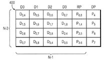
図4は、本発明の新規のR−Dパリティ技術に従って編成されたディスクアレイ400を示すブロック図である。nはアレイ内のディスク数であり、n=p+1であるものと仮定する。最初のn−2台のディスク(D0〜D3)はデータを保持し、ディスクn−1(RP)はデータディスクD0〜D3についての行パリティを保持し、ディスクn(DP)は対角パリティを保持している。この例示的実施形態では、アレイ内のディスク数nは6である。ディスクはブロックに分割され、ブロックはストライプにグループ化され、各ストライプがn−2(例えば4)行になっている。さらに、1ストライプ当たりn−1(例えば5)個の対角が存在する。
【0054】
各ブロックが1対角パリティ集合に属し、各行内で各ブロックが異なる対角パリティ集合に属するように、データブロック及び行パリティブロックに番号が付けられている。Da,b及びPa,bという記述は、データ(D)ブロック及びパリティ(P)ブロックの特定の行(a)及び対角(b)パリティ計算への寄与をそれぞれ表している。すなわち、Da,bという記述は、それらのブロックが行パリティa及び対角パリティbの計算に使用される行または対角に属していることを意味しており、Pa,bは、行パリティ集合aについてのパリティを記憶するとともに、対角パリティ集合bにも寄与することを意味している。例えば、P0,8=D0,4^D0,5^D0,6^D0,7である。この記述は、特定の対角についての対角パリティの計算に使用される行パリティブロックにも用いられ、例えばP4=D0,4^D3,4^D2,4^P1,4である。対角パリティディスク上に記憶された対角パリティブロックの各々は、アレイ内の他のディスク(行パリティディスクを含む)のうちの一台を除いて全てのディスクからの寄与を含むことに注意して欲しい。例えば、対角パリティブロックP4は、D0(D0,4)、D2(D3,4)、D3(2,4)及びRP(P1,4)からの寄与を含むが、D1からの寄与は含まない。また、対角8(P8)についての対角パリティは、計算もされず、対角パリティディスクDPに記憶もされないことに注意して欲しい。
【0055】
本発明によると、ディスクDP上の対角パリティブロックは、それらのXOR計算を行なう際に行パリティブロックも含める。すなわち、ディスクDPに記憶された対角パリティは、データディスクの内容だけでなく、行パリティディスクの内容にも従って計算される。アレイ400に示すように対角パリティブロックを符号化することにより、本システムは、対角パリティ(P8)が無くても、任意の2台の同時ディスク故障から復旧させることが可能である。これは、対角パリティディスクDP上に記憶される対角パリティブロックの計算に、行パリティブロックが要素として含まれた結果である。これに対して従来のEVENODD技術は、対角パリティ集合の計算に、行パリティブロックを要素として含めていない。むしろ、従来のEVENODDのアプローチは、対角パリティディスク上に記憶される他の対角パリティブロックの各々に、この抜けている対角パリティブロックを要素として含めている。
【0056】
動作時には、対角パリティディスクと何らかのデータディスクとが失われた場合、まず行パリティからデータディスクを復元し(例えば従来のRAID−4復元技術に従って)、次いで対角パリティディスクを復元することによって、復旧を行なうことができる。同様に、2台のパリティディスクが失われた場合、まずデータディスクから行パリティディスクを復元し、次いで対角パリティディスクを復元することによって、復旧を行なうことができる。一方、任意の一対のデータディスクが失われた場合、対角パリティ集合のうちの少なくとも1つ、大抵は2つから1ブロックを直ぐに復元することができる。続いて、システムは残りの失われたデータブロックを復元することができる。注意して欲しいのは、行パリティディスクとデータディスクが失われた場合は、2台のデータディスクが失われた場合と全く同じであり、復元も同じ方法で行なうことができる点である。
【0057】
図5は、新規のR−Dパリティ技術の復旧(復元処理)態様に必要なステップのシーケンスを示すフロー図である。このシーケンスは、ステップ500で開始して、ステップ502へ進み、ここでアレイ400の中の2台のデータディスクが故障により同時に失われたものと仮定する。故障した2台のデータディスクには任意の組み合わせがあるため、失われたデータを復元するのに行パリティを直ちに用いることはできないが、対角パリティだけは用いることができる。与えられたアレイの構造および編成(即ち、ストライプの長さとストライプの深さが等しくない)の場合、各対角は、ディスクのうちの1台からはブロックを含まない(抜けている)。そのため、2台のデータディスクが失われた場合でも、1要素しか失わない対角が2つ存在する。言い換えると、2台のディスクが失われても、それらのディスクの各々が1つの対角の要素にはなっていない。対角パリティブロックは、1つの対角を除くすべての対角についてDPディスク上に記憶されているので、ステップ504で、抜けているブロックのうちの少なくとも一方、通常2つの復元が、対角パリティを用いて開始される。
【0058】
失われたブロックを1つ復元した後、行パリティを用いてその行にある他の失われたブロックを復元することにより、行の復元を計算することができる(ステップ506)。他のブロックを復元する場合、ステップ508で、そのブロックがパリティの記憶された対角に属しているか否かについて判定を行なう。そのブロックがパリティのある対角に属している場合、その対角上にある他のディスクから、対角パリティを用いてその対角上にある他方の失われたブロックを復元することができる(ステップ510)。すなわち、抜けている対角を除くすべての対角について、その対角上の1ブロックが復元できれば、他方のブロックも復元することが可能である。その後シーケンスはステップ506へ戻り、その行パリティ集合の他方の失われたブロックを復元する。しかしながら、ブロックがパリティの無い対角(即ち、抜けている対角)に属していた場合、ステップ512で、すべてのブロックを復元し終わったか否かについて判定を行なう。まだ復元し終っていない場合、シーケンスはステップ504へ戻り、そこで対角パリティに基づく第1の復元と、続く行パリティに基づく復元とからなるパターンを繰り返し、抜けている対角パリティ集合の計算に用いられる最後のデータブロックに達するまでそれを継続する。すべてのブロックを復元し終えると、シーケンスはステップ514で終了する。この抜けている対角パリティ集合は、常に復元の連鎖の最後になる。
【0059】
具体的に、アレイ400中の隣接するデータディスクD0及びD1が失われたものと仮定する。D0は対角パリティ集合8の要素を持たず、D1は対角パリティ集合4の要素を持たない。しかしながら、対角8についてのパリティは計算も記憶もされていないので、復元の開始点は1つしかなく、それは対角4である。他の従来の2重ディスク故障パリティ訂正手段は一般に復元用の2つの開始点を有するが、本発明の一態様によると、ただ1つの開始点しか必要なく、ただ1つしか利用できない。対角4が1要素しか失っていないので、D0上のデータブロックD0,4はその対角4から直ちに復元することができ、次いでパリティディスクRP上のパリティブロックP0,8に記憶された行パリティ情報に従ってデータディスクD1上のデータブロックD0,5の復元が可能になる。
【0060】
データブロックD0,5が復元されると、対角5に抜けているのは1要素だけになるので、その要素(即ち、D0上のデータブロックD1,5)は対角パリティを用いて復元することができる。データブロックD1,5が復元されると、パリティディスクRP上のパリティブロックP1,4を用いた行パリティ復元により、D1上のD1,6の復元が可能になる。この復元の「対角−行」シーケンスは、抜けている対角パリティ集合の計算に用いられる最後のデータブロック(D1上のD3,8)に達するまで進められることに注意して欲しい。この例では、復元の連鎖は、抜けている対角パリティ集合(P8)で終了する。また、各対角について、故障したディスク間の距離(即ち、ディスク数)は、失われたデータを対角パリティ集合に沿って復元するときに通る行数に等しいことにも注意して欲しい。さらに、復元の連鎖は1つしかないが、パリティ集合8の中の1ブロックだけが失われていることにも注意して欲しい。
【0061】
他の例として、隣接するディスクD1及びD2が失われ、これによって対角パリティ集合4及び5の各々が1要素を失った場合を仮定する。対角パリティ集合5に関する失われたデータブロック(D1上のD0,5)は直ちに復元することができ、同様に対角パリティ集合4に関する失われたデータブロック(D2上のD3,4)も直ちに復元することができる。これらの復元されたブロックの各々は、上記の「対角−行」パターンに従って行パリティ情報を用いて他のデータブロックを復元するために使用することができる。これは、失われたデータディスクの復元に用いられる2つの並行復元「スレッド」の例であることに注意して欲しい。第1のスレッドはD0,5、D0,6、D1,6、D1,7、D2,7、D2,8を復元するように進められ、第2のスレッドはD0,5及びD0,6を復元するように進められる。この場合も、各スレッドは抜けている対角パリティ集合で終了する。
【0062】
次に、2台のディスクが故障したが、それらのデータディスクが隣接していない場合を仮定する。例えば、D0及びD2が失われた結果、対角パリティ集合8及び5が1要素だけ失った場合を仮定する。上記のように、対角パリティ集合8は復元処理の役に立たないので、復元チェーンは、対角パリティ集合5に関する失われたデータブロック(D0上のD1,5)から開始する。そのデータブロックの復元によって、パリティディスクRP上のパリティブロックP1,4に記憶された行パリティ情報を用いてD2上のデータブロックD1,7の復元が可能になる。失われたデータディスクが2つに分かれているので、対角パリティ集合7に関する失われたデータブロックの復元には、アレイ中を2行下がって、D0上のD3,7を通る必要がある。次いで、行パリティを用いてD2上の失われたデータブロックD3,4を復元することが可能になる。この「対角−行」パターンは、モジューロp(「循環」」)演算に従って続けられ、次にブロックがD0,4が復元され、その後D0,6、D2,6が、最後にD2,8が復元される。
【0063】
要するに、この復元のシーケンスは、復元される最初の対角から開始して抜けている対角パリティで終了する復元可能な順序で対角をリストすることによって表現することができる。kだけ離れた2台の故障したディスクj及びj+kの場合、対角の一方のシーケンスは毎回kだけ増加させることによって復元を行なうことができ、他方のシーケンスは毎回kだけ減少させることにより復元を行なうことができる。その理由は、行復元がkディスク右(または左)へ移動するので、次のkだけ大きい(または小さい)対角もモジューロpだけ移動するからである。ほとんどの場合、複数(少なくとも2つ)の並行復元スレッドが存在する。例外は、「抜けている」対角のブロックを含まないディスクであるD0と、対角パリティディスクDP以外の何らかの他のディスクが失われた場合である。その場合、復元されるブロックのストリームはただ1つしか存在せず、他方の失われたディスク上の抜けている対角パリティ集合のブロックで終了する。
【0064】
図6は、本発明に有利に用いることができるストレージオペレーティングシステム600を示す略ブロック図である。例示的実施形態では、このストレージオペレーティングシステムは、カリフォルニア州サニーベールにあるネットワークアプライアンス社から入手可能なNetApp Data ONTAP(登録商標)オペレーティングシステムが好ましく、Write Anywhere File Layout(WAFL(登録商標))ファイルシステムを実施する。本明細書で用いる場合、「ストレージオペレーティングシステム」という用語は、一般にストレージシステムにおいてストレージ機能を実施することができるコンピュータ実行可能コードを指しており、例えばファイルシステムセマンティックを実施したり、データアクセスを管理したりする。その意味で、ONTAPソフトウェアは、マイクロカーネルとして実施されるそのようなストレージオペレーティングシステムの一例であり、WAFLファイルシステムセマンティック及びデータアクセスの管理を実施するためのWAFL層を含む。また、このストレージオペレーティングシステムは、UNIX(登録商標)やWindowsNT(登録商標)等の汎用オペレーティングシステム上で動作するアプリケーションプログラムとして実施することもできるし、本明細書で説明するストレージアプリケーションのために構成されたストレージ機能または設定可能な機能を有する汎用オペレーティングシステムとして実施することもできる。
【0065】
ストレージオペレーティングシステムは、ネットワークドライバ(例えばイーサネット(登録商標)ドライバ)のメディアアクセス層610を含む一連のソフトウェア層からなる。このネットワークオペレーティングシステムは、インターネットプロトコル(IP)層612、並びに、IP層がサポートするトランスポート手段であるTCP(Transport Control Protcol)層614及びUDP(User Datagram Protocol)層616等のネットワークプロトコル層をさらに含む。ファイルシステムプロトコル層は、マルチプロトコルアクセスを提供するため、CIFS(Common Internet File System)プロトコル618、NFS(Network File System)プロトコル620、及び、HTTP(Hypertext Transfer Protocol)プロトコル622をサポートしている。さらに、オペレーティングシステム600は、RAIDプロトコル等のディスクストレージプロトコルを実施するディスクストレージ層624と、SCSI(Small Computer Systems Interface)プロトコル等のディスクアクセスプロトコルを実施するディスクドライバ層626とを含む。ディスクソフトウェア層とネットワークプロトコル層/ファイルシステムプロトコル層とを橋渡しするのは、好ましくはWAFLファイルシステムを実施するWAFL層680である。
【0066】
ストレージシステムで受信したユーザ要求に対して、データストレージアクセスを実施するのに必要な上記のストレージオペレーティングシステム層を通るソフトウェア「パス」は、代替的にハードウェアで実施することもできる。すなわち、本発明の代替の実施形態では、このストレージアクセス要求データパス650は、FPGA(Field Programmable Gate Array)やASIC(Application Specific Integrated Cirquit)の中に実現された論理回路として実施することもできる。この種のハードウェアによる実施形態は、ユーザ要求に応答してシステム220によって提供されるサービスの能力を向上させることができる。さらに、本発明のさらに他の実施形態として、アダプタ228の処理要素は、プロセッサ222からストレージアクセス処理の負荷の一部または全部を低減させるように構成し、ストレージシステムによって提供されるサービスの性能を向上させることもできる。本明細書で説明する様々な処理、アーキテクチャが、ハードウェアでもファームウェアでも、あるいはソフトウェアでも実施できることは、明らかである。
【0067】
ここまで、ストレージアレイの対角パリティを計算するためのオーバヘッドを低減させるR−Dパリティ技術の例示的実施形態を図示及び説明してきたが、本発明の思想及び範囲から外れることなく、様々な変更及び修正が可能であることは明らかである。例えば本発明は、すべてのパリティ情報が2台のディスク上に記憶されるRAID−4に類似した集中パリティ配置に構成するのに適しているが、RAID−5に類似した分散パリティ配置や、他の分散パリティ配置にも適用することが可能である。後者の分散パリティ配置によると、異なる行の集合内で、1行当たり2ブロックのパリティが存在し、アレイ内でそれらのパリティの位置がディスクごとにシフトされる。
【0068】
行パリティ集合及び対角パリティ集合の完全なグループを保持し、行のグループ全体がその行内のいかなる2台のディスクの損失からも復旧可能であるようにするためには、本発明は、p−1行のグループが必要であることが分かっている。例示的実施形態では、このグループの行は、ディスクアレイのディスクの隣接した行である。また、アレイが集中パリティスタイルに構成され、すべてのパリティ情報が2台のディスク上に存在する場合、必ずしもすべてのデータディスクが必要なわけではないことも分かっている。2台のパリティディスクが必要であり、それらが通常少なくとも1台のデータディスクを伴う。しかしながら、必ずしもアレイ内に全部でp−1台のデータディスクが存在する必要はない。存在しないディスクは、全てゼロ、即ちゼロのデータを保持するディスクが存在するかのように扱われる。そのため、パリティ値に全く関与することがなく、パリティの復元や故障したディスクの復旧に用いられるアルゴリズムの邪魔にはならない。
【0069】
アレイを構成するための特に優れた選択である、いくつかの素数が存在する。これらは2のべき乗+1の素数であって、ディスクアクセスに用いられるブロックサイズよりも小さく、アレイ内のディスク数以上の数である。最初の素数、2のべき乗+1は、5、17及び257である。そのうち、5ではディスクアレイが最大で4台のデータディスクしか持てないので、多くの場合小さすぎるであろう。しかしながら、17と257はいずれも良い選択である。その理由は、大抵のストレージシステムはディスクストレージをブロックに分割しており、1ブロックが2のべき乗の大きさ、典型的には4k(4096)バイト、8k(8192)バイト、あるいは同様に2の何らかのべき乗の大きさであるからである。p=17またはp=257にすると、対角パリティは16行または256行のグループ内で計算され、アレイ内には、最大15または255台のデータディスクがそれぞれ保持される。これらの選択はいずれもデータブロックを均等に分割することができ、例えば4kバイトの大きさのブロックを、4k/16=256バイトまたは4k/256=16バイトにそれぞれ分割できるので、妥当な選択である。対角パリティは、サブブロックに沿って対角を定義することにより、計算される。行パリティは、対角パリティを持たないRAID−4またはRAID−5アレイで計算するのとちょうど同じ方法で、例えば4kブロック全体に対してパリティを計算することにより、計算することができる。
【0070】
各ディスクブロックは対角パリティ集合計算の目的で16または256個のサブブロックに均等に分割することができるが、ソフトウェアまたはハードウェアによるこの方法の実施形態は、例示的実施形態として、4k対角パリティに重なることがない1つ又は2つの連続した4kブロックの領域であって、各々が1以上のサブブロックからなる4kブロックの領域のXORが必要である。これらのデータブロックの内容のXORをとってシフトパターンで対角パリティブロックに入れ、抜けている対角パリティ集合に属する各データブロックのサブブロックを対角パリティブロックから除外する。対角パリティデータを対角パリティブロックに加算するための総計算時間は、データブロックを行パリティブロックに加算するための計算時間に匹敵する。
【0071】
有利なことに、本発明は、例えば、すべてのパリティ情報がディスク等の2つの装置に記憶されるRAID−4スタイルの集中パリティフォーマットにおいて、2重ディスク故障パリティ保護を提供する。従って、本発明の技術によると、データディスクを再フォーマットしたり既存のパリティ情報を再計算したりすることなく、データディスクをディスクアレイに徐々に追加してゆくこと可能になる。本発明は、最小量の冗長ディスク空間、即ち、1アレイ当たりちょうど2台のディスクしか利用しない。また、本発明は、EVENODD等の従来技術のアプローチに比べて、所与のデータディスク数について、パリティ計算のオーバヘッドも低減している。
【0072】
上記の説明は、本発明の特定の実施形態に関して行なっている。しかしながら、説明した実施形態に対して他の様々な変更及び修正を行い、本発明の利点のうちのいくらかまたは全部を得ることも可能であることは明らかである。従って、付記した請求の範囲の目的は、かかる変更及び修正が本発明の真の思想及び範囲に入るようにすることである。
【図面の簡単な説明】
【図1】従来のEVENODDパリティ配置に従って構成された従来技術のディスクアレイを示す略ブロック図である。
【図2】本発明に有利に用いられる、ストレージシステムを含む環境を示す略ブロック図である。
【図3】本発明の行−対角(R−D)パリティ技術を含むステップシーケンスを示すフロー図である。
【図4】新規のR−Dパリティ技術に従って攻勢されたディスクアレイを示すブロック図である。
【図5】本発明によるRDパリティ技術の復元処理に必要なステップのシーケンスを示すフロー図である。
【図6】本発明に有利に用いられるストレージオペレーティングシステムを示す略ブロック図である。[0001]
BACKGROUND OF THE INVENTION
The present invention relates to an array of a storage system, and more particularly to a technique for efficiently restoring any one failed storage device or a combination of any two failed storage devices in a storage array. .
[0002]
[Prior art]
A storage system usually includes one or more storage devices, and data can be input to or acquired from those storage devices as required. The storage system is implemented according to various storage architectures including, but not limited to, a storage environment attached to a network, a storage area network, and a disk assembly directly attached to a client or host computer. The storage device is typically a disk drive, where the term “disk” generally refers to a stand-alone rotating magnetic media storage device. The term “disk” in this context is synonymous with hard disk drive (HDD) or direct access storage device (DASD).
[0003]
The disks in the storage system are usually organized into one or more groups, and each group is operated as a RAID (Redundant Array of Independent (or Inexpensive) Disks). Most RAID embodiments rely on data storage reliability by redundant writing of data across a “striped” form of a predetermined number of physical disks in a RAID group and appropriate storage of redundant information about the striped data. To improve performance / integrity. This redundant information makes it possible to recover the data lost when the storage device fails.
[0004]
When operating a disk array, it is considered that a disk may fail. The goal of high performance storage systems is to make MTTDL (Mean time to data loss) as long as possible, preferably longer than the estimated service life of the system. If one or more disks fail, the data may be lost, making it impossible to recover the data from that device. Common means to avoid data loss include mirroring, backup, and parity protection. Mirroring is an expensive solution from the perspective of consuming storage resources such as disks. A backup cannot protect data that has changed since the backup was created. Parity means is common because it provides redundant encoding of data with the addition of only one disk drive to the system and allows single deletion (loss of one disk).
[0005]
Parity protection is used in computer systems to prevent data loss on storage devices such as disks. The parity value is calculated by adding (usually modulo 2) data of a certain word size (usually 1 bit) across a number of similar disks with different data. That is, the parity is calculated for a 1-bit wide vector composed of bits at corresponding positions on each disk. When calculated for a one-bit wide vector, the parity may be calculated as a sum or as its complement, which are referred to as even parity and odd parity, respectively. Addition and subtraction for 1-bit vectors are both the same as exclusive OR (XOR) operations. The data is then protected from the loss of any one of the disks, or the loss of any part of any one of the disks. If the disk storing the parity is lost, the parity can be regenerated from the data. If one of the data disks is lost, the data can be regenerated by adding the contents of the remaining disks and subtracting the result from the stored parity.
[0006]
Usually, the disks are divided into parity groups, each of which includes one or more data disks and one parity disk. The parity set is a set of blocks including a plurality of data blocks and one parity block, where the parity block is an XOR of all the data blocks. A parity group is a set of disks from which one or more parity sets are selected. The disk space is divided into stripes, and each stripe holds one block from each disk. A stripe block usually exists at the same location on each disk in a parity group. Within the stripe, all blocks except for one block are blocks that hold data (“data block”), and one block holds a block (“parity”) that is calculated by XORing all of those data. Block "). When all of these parity blocks are stored on one disk and a single disk that holds all parity information (and only parity information) is provided, this is a RAID-4 embodiment. If these parity blocks are kept in different disks in each stripe, a circular pattern is often used and the embodiment is RAID-5. The term “RAID” and its embodiments are widely known, and in June 1998, the minutes of the International Conference on Data Management (SIGMOD) A. Patterson, G.M. A. Gibson, and R.A. H. It is disclosed in “A Case for Redundant Arrays of Inexpensive Disks (RAID)” by Katz.
[0007]
As used herein, the term “encoding” refers to the calculation of redundancy values over a given subset of data blocks, whereas the term “decoding” It means the restoration of the data block or parity block by that same process in the redundancy calculation using the subset and the redundancy value. If one disk fails in a parity group, the contents of that disk are decoded (restored) onto the spare disk by adding all the contents of the remaining data blocks and subtracting the result from the parity block. can do. Since 2's complement addition and subtraction on a 1-bit field are both equivalent to XOR operations, this reconstruction consists of XOR of all surviving data blocks and parity blocks. Similarly, if a parity disk is lost, the parity disk can be recalculated in the same way from the surviving data.
[0008]
The parity means generally provides protection against one failure in the parity group. These measures can also provide protection against multiple disk failures as long as the failures occur in different parity groups. However, if two disks in the parity group fail simultaneously, unrecoverable data loss occurs. It is fairly common for two disks in a parity group to fail at the same time, especially due to disk wear and environmental factors related to disk operation. In this context, the simultaneous failure of two disks within a parity group is called a “double failure”.
[0009]
A double failure typically occurs as a result of one disk failure and another disk failure that occurred while attempting to recover from that initial failure. The recovery time or restoration time depends on the level of activity of the storage system. That is, while restoring a failed disk, the storage system remains “online” and can provide services for requests (from clients or users) to access (read and / or write) data. It is. If the storage system is busy servicing the request, the restoration time will increase. Since it is necessary to read all of the surviving disks in order to restore the lost data, this restoration processing time increases as the number and size of the disks in the storage system increase. The double failure probability is proportional to the square of the number of disks in the parity group. However, reducing the parity group is expensive because each parity group requires an entire disk to handle redundant data.
[0010]
Another failure mode of the disk is a media read error in which one block or one sector in the disk cannot be read. If the parity is held in the storage array, the unreadable data can be restored. However, if one disk has already failed and there is a read error for other disks in the array, data is lost. This is the second form of double failure.
[0011]
Accordingly, it is desirable to provide a technique that is resistant to double failure. While this technique allows the configuration of a larger disk system with a larger parity group, the system can be duplicated even in the case of restoration after a long time (for example, several hours) for a single disk failure. Guarantee that it will withstand failure. Such a technique can alleviate certain design restrictions on the storage system. For example, the storage system will be able to use lower cost disks and still maintain a high MTTDL. A low-cost disk generally has a shorter life than a high-cost disk and has a higher probability of failure during the lifetime. Therefore, if the storage system can withstand a double disk failure in a parity group, the use of such a disk becomes more possible.
[0012]
It can be easily shown that the minimum amount of redundant information required to correct a double failure is two units. Therefore, the minimum number of parity disks that can be added to the data disk is two. This is true regardless of whether parity is distributed across multiple disks or concentrated on two additional disks.
[0013]
A known double failure correction parity means is an EVENODD XOR based technique that allows for sequential recovery of lost (failed) disks. EVENODD parity requires redundant data for exactly two disks, which is optimal. According to this parity technique, all disk blocks belong to two parity sets, one is a
[0014]
The EVENODD technique uses p + 2 disks in total, where p is a prime number, of which p disks hold data, and the remaining two disks hold parity information. One parity disk holds row parity blocks. Row parity is calculated as the XOR of all data blocks at the same location on each data disk. The other parity disk holds diagonal parity blocks. The diagonal parity is composed of p-1 data blocks arranged in a diagonal pattern on a plurality of data disks. These blocks are grouped into p-1 row stripes. This does not affect the allocation of data blocks to row parity sets. However, the diagonal is configured in a pattern such that all blocks within the diagonal fall within the same block stripe. This means that most diagonals "circulate" within the stripe as they go from disk to disk.
[0015]
Specifically, for an array of n × (n−1) data blocks, if the diagonal “circulates” at the end of the array, there are exactly n diagonals of length n−1. What is important in the restoration of the EVENODD parity arrangement is that each diagonal parity set does not hold information from one of the data disks. However, there is only one diagonal other than there is a block for storing parity blocks for the diagonal. That is, the EVENODD parity arrangement results in a diagonal parity set that does not have an independent parity block. To accommodate this extra “missing” parity block, the EVENODD constellation XORs a particular diagonal parity result with the parity block for each of the other diagonals.
[0016]
FIG. 1 is a schematic block diagram illustrating a prior
[0017]
In order to recover from the failure of two data disks, first, XOR of all the parity blocks is taken to recalculate the diagonal parity having no parity block. For example, the sum of all row parities is the sum of all data blocks. The sum of all diagonal parities is the sum of all data blocks minus the sum of missing diagonal parity blocks. Therefore, the XOR of all parity blocks is equal to the sum of all blocks (total row parity) minus the sum of all blocks excluding the missing diagonal, which is just the missing diagonal parity. become. In practice, n-1 duplicates of missing diagonal parity, one for each diagonal parity block, are added to the result. Since n is a prime number greater than 2, n−1 is an even number, and the result of XORing a certain block with itself an even number of times is a zero block. Therefore, even if no additional diagonal parity is added, the sum of those diagonal parity blocks with the missing parity added to each is equal to the sum of the diagonal parity blocks.
[0018]
Next, the missing diagonal parity is subtracted from each of the diagonal parity blocks. After two data disks fail, there are at least two diagonal parity sets in which only one block is lost. Blocks lost from each of those parity sets can be recovered if one set is diagonal with no parity blocks. When these blocks are restored, all but one element is available for the two row parity sets. This allows the lost elements of those rows to be restored. This restoration provides enough information for the other diagonal to restore only one lost block on the diagonal. This restoration pattern, which alternately uses row parity and diagonal parity, continues until all lost blocks have been restored.
[0019]
Since n is a prime number, no cycle is formed during restoration until all diagonals are encountered, ie, all lost data blocks have been restored. The situation is different if n is not a prime number. If both parity disks are lost, a simple restoration of the parity from the data can be performed. When the data disk and the diagonal parity disk are lost, after performing a simple RAID-4 style restoration of the data disk using the row parity, the diagonal parity disk is restored. If the data disk and row parity disk are lost, one diagonal parity can be calculated. Since all diagonals have the same parity, it is then possible to calculate the lost blocks on each diagonal.
[0020]
Since each data block is an element of the diagonal parity set, when two data disks are lost (double failure), there are two diagonal parity sets in which only one element is lost. Each disk has a diagonal parity set that does not appear on that disk. Therefore, in the case of a double failure, there are two diagonal parity sets that can be restored. EVENODD can recover from failure of both parity disks and failure of any combination of one data disk and one parity disk. In addition, this technology can also restore from any one disk failure.
[0021]
The EVENODD technique is optimal for the amount of parity information, but is only asymptotically optimal for the amount of computation required for both encoding and decoding. The reason is the extra computation required to add missing diagonal parity to each of the diagonal parity blocks. That is, p-1 blocks in one stripe are insufficient to hold p parity blocks generated from p diagonals. In order to overcome this, the EVENODD technique needs to XOR one parity of the diagonals with all other diagonal parity blocks, increasing the computational overhead.
[0022]
In general, a write process to a diagonal data block that does not have a direct parity block must update all diagonal parity blocks for any small write process. Also, extra calculations are required for large write processing. As used herein, “large write” processing includes rewriting all blocks of one stripe, and “small write” processing includes changing at least one data block and associated parity.
[0023]
Summary of the Invention
The present invention provides a "row-diagonal" that reduces diagonal parity computation overhead for a storage array configured to allow efficient recovery from simultaneous failure of two storage devices in the storage array. (R-D) parity technique. This RD parity technique is preferably used in a storage device such as a number n of disks including a row parity disk and a diagonal parity disk, where p is a prime number and n =
[0024]
In accordance with the present invention, the RD parity technique includes the calculation of row parity along each row of data disks in the array, and then when calculating the diagonal parity to be stored on the diagonal parity disk, the row parity block. And data blocks are not distinguished. In other words, the diagonal parity is calculated along the diagonal over the combined range of all data disks and row parity disks. In addition, parity is stored on the diagonal parity disk for all diagonals except one diagonal. In other words, the diagonal parity disk holds a parity block for each diagonal except one in the stripe. The technology of the present invention also provides sufficient information to recover from any two simultaneous disk failures in the array, even if no parity is stored (or calculated) for one of the diagonals. To do.
[0025]
Advantageously, the technique of the present invention minimizes the computational burden for calculating the parity stored in the array during failure-free operation. The present invention also minimizes the overhead of parity calculation and requires less calculation for a predetermined number of data disks than conventional methods such as EVENODD. The RD parity technique of the present invention speeds recovery by minimizing the total amount of computation required to recover lost data. Furthermore, the present invention can also be implemented using a centralized parity technique, in which case all row parity blocks are stored on the same disk and the data disk is not reformatted or recalculated. Can be gradually added to the array. The only limitation on adding data disks to the array is that the maximum number of disks available in the array must be predetermined (important). This limitation is due to the use of diagonals and the length of those diagonals depending on the stripe depth. The difference between the actual number of disks present and the maximum number of disks in the array is filled with “virtual” disks that hold only zero-valued data.
[0026]
The present invention can also be implemented using a distributed parity arrangement for the row parity arrangement. For example, the present invention may be implemented by adding one diagonal parity disk to a RAID-5 array having a prime number of disks. The present invention will work with any prime disk configuration that allows for a single disk failure using redundancy such as parity within a row. In such a case, the present invention is implemented by adding a single disk to the array dedicated to diagonal parity, and using normal parity calculations across the diagonal defined on the disks of the original array. Calculate parity.
[0027]
The description of the invention relates to a centralized parity embodiment in which all row parity is stored on one disk.
[0028]
The above and further advantages of the present invention may be better understood by reference to the following description taken in conjunction with the accompanying drawings, in which like reference characters identify the same or functionally similar elements. Show.
[0029]
FIG. 2 is a schematic block diagram illustrating an
[0030]
In the exemplary embodiment,
[0031]
[0032]
Storage of information on the
[0033]
The present invention includes a “row-diagonal” (RD) parity technique that provides double failure parity correction recovery using row and diagonal parity within the disk array. The technique of the present invention is implemented by the disk storage layer (shown at 624 in FIG. 6) of the
[0034]
In general, the present invention includes n storage devices, where n = p + 1, where p is a prime number. These storage devices are divided into blocks of the same size. Within each device, n-2 blocks are arbitrarily selected and grouped to form a stripe across all devices. One device is designated in the stripe to hold the parity formed by selecting a block from other devices as input. As a result of the simplified creation technique described further herein, this device is called a diagonal parity device, and the parity it holds is called diagonal parity. Within each stripe, one block is selected from each of the devices other than the diagonal parity device in the stripe. This set of blocks is called a row. One block in a row is selected to hold the parity for that row, and the remaining blocks hold data. Row building continues until all the blocks other than the diagonal parity device in the stripe are assigned to exactly one row. There are n-2 lines in all.
[0035]
Within each stripe, select one block from each device except one of all devices other than the diagonal parity device in the stripe, and the restriction that two of the selected blocks do not belong to the same row Add more. This is called a diagonal parity set or “diagonal”. For example, the diagonal numbers data devices, row parity devices, and diagonal parity devices from 0 to n-1, each row is numbered from 0 to n-3, and the blocks in device i, row j Can be formed by assigning to the diagonal (i + j + 1) mod (n-1). This diagonal formation continues until all of the blocks that are not on the diagonal parity device in the stripe are assigned diagonally, so that there are no two diagonals from the same device that do not contain all blocks. Add more restrictions. n-1 diagonals. n-2 diagonals are selected from n-1 diagonals. These blocks within a diagonal are combined to form a diagonal parity block, whether it holds data or holds parity. These n-2 diagonal parity blocks are stored in any order in the n-2 blocks of the stripe on the device that holds the diagonal parity within the stripe.
[0036]
The present invention selects a row holding a block at the same position on each disk, selects a continuous group of n-1 rows to form a stripe, and further selects a block within that stripe to select each pair. It can also be implemented simply by forming a diagonal pattern that circulates through the corner blocks. Furthermore, the present invention can be implemented by storing all row parity blocks of a stripe in the same device of the stripe. In a preferred embodiment, the present invention can be implemented by keeping the same application of the device as a row parity device, diagonal parity device or data device, even if the stripes are different. Alternatively, in another preferred embodiment of the present invention, it can be implemented as a row parity device, a diagonal parity device, or a data device by rotating or changing the usage of the device for each different stripe.
[0037]
Parity is generally calculated as an exclusive OR (XOR) of data blocks to form a parity block. The XOR operation is typically performed on the same 1-bit field of each input block to produce one corresponding output bit. As described above, this XOR operation is the same as two's complement addition or subtraction of two 1-bit fields. Redundant parity information is also calculated as the sum of a plurality of bit fields of the same size (for example, 8, 16, 32, 64, 128 bits) at all inputs. For example, the parity equivalent can be calculated by adding data using two's complement addition to a 32-bit field, each generating 32-bit redundancy information. Since the XOR between a block and the block itself is zero, this is only possible assuming that it is unreliable that the XOR operation on two identical inputs of the block will be the original contents of the block. . The technique of the present invention described herein does not depend on the XOR aspect, and can be implemented by addition and subtraction on fields larger than 1 bit.
[0038]
It can be said that it is common to store the direct XOR sum of data bits as a parity bit value. This method is often referred to as “even parity”. Alternatively, the complement of the XOR sum of data bits may be stored, which is called “odd parity”. For the invention disclosed herein, the use of even or odd parity is not specified. However, when such distinction is a problem, the algorithm referred to in this specification is described as using even parity. It will also be apparent to those skilled in the art that odd parity can be used in accordance with the teachings of the present invention.
[0039]
Those skilled in the art may understand that a block (for parity calculation) may or may not correspond to a file block, database block, disk sector, or other convenient sized unit. It will be clear. It is not absolutely necessary that the block size used for parity calculation has any relationship with other block sizes used in the system. However, it is desirable that one or more integer parity blocks fit exactly in a unit defined as one or more integer disk sectors. In many cases, some blocks correspond to file system blocks or database blocks, which are typically 4k (4096) bytes or 2 factorial bytes (eg, 8k, 16k, 32k). 64k, 128k, 256k).
[0040]
The exemplary system described herein preferably performs a full stripe write process. In particular, it is preferable to divide individual file blocks, which are typically 4k or 8k bytes, into smaller blocks that are only used for parity calculations, so that, for example, all stripes of 4k byte sized blocks can be written to the disks of the array. . When writing all stripes to disk, all parity calculations are performed in memory before writing the results to disk, reducing the burden of parity calculation and update on the disk.
[0041]
FIG. 3 is a flow diagram illustrating a sequence of steps including the RD parity technique of the present invention. The sequence starts at
[0042]
Next, in
[Table 1]
As long as the two blocks in a row do not belong to the same diagonal parity set, changing the position of the elements in each column without changing the feature that the array can be restored from any two disk failures The position of the column can be changed. Without loss of generality, it is estimated that blocks can be assigned to diagonal parity sets in a manner substantially according to Table 1. It is also possible to change the elements of the blocks in the row.
[0044]
As described above, the parity of the diagonal parity set is stored on the diagonal parity disk. According to the present invention, the RD parity technique does not distinguish between row parity blocks and data blocks when calculating the diagonal parity stored on the diagonal parity disk. In other words, all the disks in the original array are treated equally and the information stored in one of them can be recovered from the XOR sum of all the other disks in the row parity set. ing. Accordingly, the diagonal parity disk stores the diagonal parity computed along the diagonal parity set across all data disks and row parity disks in the array (step 314). The role of a disk, such as a data disk, row parity disk or diagonal parity disk, varies from stripe to stripe, enabling a RAID 5 style distributed parity embodiment.
[0045]
However, there is not enough space on the diagonal parity disk to hold all the parity information for the p diagonals defined on the p-1 row. Specifically, there is only enough space for the diagonal parity of the p-1 block. Each data disk and row parity disk has at most one block belonging to one diagonal, and there is no row including two blocks that are the elements of the same diagonal regardless of whether it is data or row parity. There are exactly p diagonals in one stripe, but there are only p-1 diagonal parity blocks on the diagonal parity disk.
[0046]
To overcome this, diagonal parity is not stored on the diagonal parity disk for one of the diagonal parity sets (step 316). That is, the diagonal parity disk holds a parity block for each diagonal except for one diagonal in one stripe. The selection of which diagonal parity block is not stored is arbitrary. Since the parity is not stored, it is not calculated. Also, even if no parity is stored for one of the diagonals, the technique of the present invention can provide sufficient parity information to recover from any two simultaneous disk failures in the array. it can. That is, if any two disks are lost, the entire contents of one stripe can be restored according to the restoration mode of the present invention (step 318). In
[0047]
Since the row parity disk and the data disk are not distinguished when the disk is allocated diagonally, the distinction between the row parity disk and the data disk can be ignored when dealing with restoration from the diagonal parity set. To illustrate this, consider the case where any two data disks or any one data disk and row parity disk are lost. A lost block in a parity set can only be recovered if all other blocks that make up that parity set are available. The subtlety of XOR parity is that all blocks are mathematically equivalent, regardless of whether the block initially held data or parity. For example, let us consider a parity configuration a ^ b ^ c = d where "^" represents an XOR operator. If both sides are XORed with d, a ^ b ^ c ^ d = 0. Therefore, all data disks and row parity disks can be treated as the same during restoration.
[0048]
In each of these disks, only one diagonal does not appear. Thus, restoration can be started from on another disk that does not include the diagonal element. When two disks fail, in most cases there are two blocks that can be immediately recovered from the diagonal parity data. This is true unless one of the diagonals that lost only one block is a diagonal with no parity stored. However, since usually only one disk has lost data for its parity set, there is at least one block that can be recovered immediately. When one or two blocks are restored from diagonal parity, only one block is missing in the row parity set that has blocks restored using diagonal parity (not including diagonal parity blocks) at that time. So, that row or other lost blocks of those rows can be recovered from row parity. After restoring these blocks, one or more blocks on the same diagonal can be restored as row blocks.
[0049]
Thus, the restoration proceeds by a series of diagonal “movements” and horizontal “movements”. Since p is a prime number, a series of horizontal and diagonal moves will move every row in the stripe until it hits the same row twice. Also, since no parity is stored for the diagonal, there is one diagonal that cannot be diagonally moved beyond that diagonal. Without loss of generality, the diagonals are numbered from 0 to p-1, and parity is calculated for all diagonals except for the diagonal zero. Therefore, diagonal movement along the diagonal zero is impossible. For disks that are a predetermined distance apart in the array, there is always a recoverable diagonal fixed sequence that ends at zero diagonal. If the disks are numbered from 0 to p-1 and the circulation between the disks is considered such that the disk p-1 (row parity disk) is adjacent to the disk 0, (p-1) sequences can be considered. Each sequence corresponds to the reconstruction of any pair of disks separated by that distance. For example, Table 2 illustrates a sequence when p = 13.
[Table 2]
Note that the sequence for disk k always starts with diagonal k, continues each time by incrementing j and taking modulo p, ending with p mod p = 0. Also note that the first p-term of the sequence when the disk k is separated is the reverse order of the first p-term of the sequence when the disk p-k is separated.
[0051]
The starting position in the sequence is determined according to which disk pair has failed. If the disks and diagonals are numbered according to the previous explanation, that is, the disks are numbered consecutively from 0 to n-1 and the rows are numbered consecutively from 0 to n-3. In each disk j, when the block i of the disk j belongs to the diagonal parity set (i + j + 1) mod (n−1), the missing diagonal is always the diagonal j. Thus, for a pair of disks separated by k, the two diagonals from which repair can be initiated are j and (j + k) mod (n-1). Note that these two diagonals are always next to each other in a restoration sequence separated by disk k. In these two sequences, the restoration proceeds in a diagonal sequence determined by moving to the right from the starting point, and when separated from disk k, it starts from the symbol (j + k) mod (n−1) and disk p If -k away, start at symbol j with k <p / 2. Therefore, even when any combination of two data disks fails or when one data disk and row parity disk fail, complete restoration is always possible. If a diagonal parity disk and another disk fails, restore the other failed disk from the stored row parity, regardless of whether the other failed disk is a data disk or a row parity disk Then it is easy to restore the diagonal parity disk. As a result, the RD parity technology of the present invention makes it possible to recover from any two disk failures.
[0052]
Note that not all data blocks belong to the calculated diagonal of parity. In fact, diagonal parity is only calculated for (p-1) / p of the data blocks and for the row parity block. Updating one block is costly because not only the row parity block of that block but also the diagonal parity block of that block must be recalculated. When the row parity is updated for one block, the diagonal parity block of the row parity block must be changed. However, this can be simplified in a system composed of sub-blocks where the stripe is one “block” wide and is used only for parity calculations. In that case, a parity update is calculated and added to the row parity. The same parity update block portion is also directly added to the diagonal parity block portion of the stripe.
[0053]
FIG. 4 is a block diagram illustrating a
[0054]
Data blocks and row parity blocks are numbered so that each block belongs to one diagonal parity set and each block belongs to a different diagonal parity set within each row. D a, b And P a, b The description represents the contribution to the specific row (a) and diagonal (b) parity calculations of the data (D) block and parity (P) block, respectively. That is, D a, b Means that these blocks belong to the row or diagonal used for the calculation of row parity a and diagonal parity b, and P a, b Means that the parity for the row parity set a is stored and also contributes to the diagonal parity set b. For example, P 0,8 = D 0,4 ^ D 0,5 ^ D 0,6 ^ D 0,7 It is. This description is also used for row parity blocks that are used to calculate diagonal parity for a particular diagonal, eg P Four = D 0,4 ^ D 3,4 ^ D 2,4 ^ P 1,4 It is. Note that each diagonal parity block stored on a diagonal parity disk includes contributions from all but one of the other disks in the array (including the row parity disk). I want you. For example, diagonal parity block P Four Is D0 (D 0,4 ), D2 (D 3,4 ), D3 ( 2,4 ) And RP (P 1,4 ) But not from D1. Diagonal 8 (P 8 Note that the diagonal parity for) is neither calculated nor stored on the diagonal parity disk DP.
[0055]
According to the present invention, diagonal parity blocks on disk DP also include row parity blocks when performing their XOR calculations. That is, the diagonal parity stored in the disk DP is calculated according to the contents of the row parity disk as well as the contents of the data disk. By encoding the diagonal parity block as shown in the
[0056]
In operation, if the diagonal parity disk and any data disk are lost, first recover the data disk from row parity (eg, according to conventional RAID-4 recovery technique), then restore the diagonal parity disk, Recovery can be performed. Similarly, if two parity disks are lost, recovery can be performed by first restoring the row parity disk from the data disk and then restoring the diagonal parity disk. On the other hand, if any pair of data disks is lost, at least one of the diagonal parity sets, usually two to one, can be restored immediately. Subsequently, the system can recover the remaining lost data blocks. It should be noted that when the row parity disk and the data disk are lost, it is exactly the same as when the two data disks are lost, and the restoration can be performed in the same manner.
[0057]
FIG. 5 is a flowchart showing a sequence of steps necessary for the recovery (restoration processing) mode of the new RD parity technique. The sequence begins at
[0058]
After restoring one lost block, row restoration can be computed by restoring other lost blocks in that row using row parity (step 506). When restoring another block, a determination is made at
[0059]
Specifically, assume that adjacent data disks D0 and D1 in
[0060]
Data block D 0,5 Is restored, only one element is missing in the diagonal 5, so that element (ie, the data block D on D0) 1,5 ) Can be recovered using diagonal parity. Data block D 1,5 Is restored, the parity block P on the parity disk RP 1,4 D on D1 due to row parity recovery using 1,6 Can be restored. This "diagonal-row" sequence of restoration is the last data block (D on D1) used to calculate the missing diagonal parity set. 3,8 Note that you can proceed until you reach). In this example, the restoration chain ends with the missing diagonal parity set (P8). Also note that for each diagonal, the distance between the failed disks (ie, the number of disks) is equal to the number of rows passed when recovering lost data along the diagonal parity set. Also note that although there is only one reconstruction chain, only one block in the parity set 8 is lost.
[0061]
As another example, assume that adjacent disks D1 and D2 are lost, causing each of diagonal parity sets 4 and 5 to lose one element. Lost data block (D on D1) for diagonal parity set 5 0,5 ) Can be recovered immediately, as well as the lost data block (D on D2) for diagonal parity set 4 3,4 ) Can also be restored immediately. Each of these recovered blocks can be used to recover other data blocks using row parity information according to the “diagonal-row” pattern described above. Note that this is an example of two parallel restore “threads” used to restore a lost data disk. The first thread is D 0,5 , D 0,6 , D 1,6 , D 1,7 , D 2,7 , D 2,8 , And the second thread is D 0,5 And D 0,6 Proceed to restore. Again, each thread ends with the missing diagonal parity set.
[0062]
Next, assume that two disks have failed but the data disks are not adjacent. For example, assume that the diagonal parity sets 8 and 5 have lost only one element as a result of the loss of D0 and D2. As mentioned above, since the diagonal parity set 8 is not useful for the restoration process, the restoration chain is a lost data block for the diagonal parity set 5 (D on D0). 1,5 ). By restoring the data block, the parity block P on the parity disk RP 1,4 A data block D on D2 using the row parity information stored in 1,7 Can be restored. Since the lost data disk is split in two, the recovery of the lost data block for the diagonal parity set 7 can be done by going down the array by 2 rows and D on D0. 3,7 It is necessary to pass through. Then the lost data block D on D2 using row parity 3,4 Can be restored. This “diagonal-row” pattern is followed according to a modulo p (“circular”) operation, and then the block is D 0,4 Is restored, then D 0,6 , D 2,6 But finally D 2,8 Is restored.
[0063]
In short, this restoration sequence can be expressed by listing the diagonals in a recoverable order starting with the first diagonal to be restored and ending with the missing diagonal parity. For two failed disks j and j + k separated by k, one of the diagonal sequences can be restored by increasing by k each time, and the other sequence can be restored by decreasing by k each time. Can be done. The reason is that since the row restoration moves to the right (or left) of the k disk, the next larger (or smaller) diagonal by k is also moved by the modulo p. In most cases, there are multiple (at least two) concurrent restore threads. An exception is when D0, which is a disk that does not contain “missing” diagonal blocks, and some other disk other than the diagonal parity disk DP is lost. In that case, there is only one stream of blocks to be restored, ending with a block of missing diagonal parity set on the other lost disk.
[0064]
FIG. 6 is a schematic block diagram illustrating a
[0065]
The storage operating system consists of a series of software layers including a media access layer 610 for a network driver (eg, Ethernet driver). This network operating system further includes an Internet protocol (IP) layer 612 and network protocol layers such as a TCP (Transport Control Protocol)
[0066]
The software “path” through the storage operating system layer described above required to perform data storage access to user requests received at the storage system can alternatively be implemented in hardware. That is, in an alternative embodiment of the present invention, the storage access request data path 650 can be implemented as a logic circuit implemented in an FPGA (Field Programmable Gate Array) or an ASIC (Application Specific Integrated Circuit). This type of hardware embodiment can improve the capabilities of services provided by
[0067]
Up to this point, an exemplary embodiment of an RD parity technique for reducing overhead for calculating diagonal parity of a storage array has been shown and described, but various modifications may be made without departing from the spirit and scope of the present invention. Obviously, modifications are possible. For example, the present invention is suitable for a centralized parity arrangement similar to RAID-4 in which all parity information is stored on two disks, but a distributed parity arrangement similar to RAID-5, etc. The present invention can also be applied to other distributed parity arrangements. According to the latter distributed parity arrangement, there are two blocks of parity per row in different sets of rows, and the positions of those parity in the array are shifted from disk to disk.
[0068]
In order to maintain a complete group of row parity sets and diagonal parity sets so that the entire group of rows can be recovered from the loss of any two disks in the row, the present invention provides p- It turns out that a group of one line is needed. In the exemplary embodiment, this group of rows is a contiguous row of disks in the disk array. It has also been found that not all data disks are required if the array is configured in a centralized parity style and all parity information is on two disks. Two parity disks are required and they usually involve at least one data disk. However, it is not always necessary to have a total of p-1 data disks in the array. A non-existing disk is treated as if there is a disk holding all zeros, that is, zero data. Therefore, it is not involved in the parity value at all, and does not interfere with the algorithm used for restoring the parity or restoring the failed disk.
[0069]
There are several prime numbers that are particularly good choices for constructing arrays. These are powers of 2 + 1 and a prime number that is smaller than the block size used for disk access and is greater than or equal to the number of disks in the array. The first prime number, power of 2 + 1 is 5, 17 and 257. Of these, 5 would be too small in many cases because the disk array can only have a maximum of 4 data disks. However, both 17 and 257 are good choices. The reason is that most storage systems divide disk storage into blocks, where one block is a power of two, typically 4k (4096) bytes, 8k (8192) bytes, or 2 This is because it is some power. With p = 17 or p = 257, diagonal parity is calculated within a group of 16 or 256 rows, and up to 15 or 255 data disks are held in the array, respectively. Any of these selections can divide the data block equally, for example, a block of size 4k bytes can be divided into 4k / 16 = 256 bytes or 4k / 256 = 16 bytes, respectively. is there. Diagonal parity is calculated by defining the diagonal along the sub-block. Row parity can be calculated in exactly the same way as for a RAID-4 or RAID-5 array without diagonal parity, for example by calculating parity for the entire 4k block.
[0070]
Although each disk block can be equally divided into 16 or 256 sub-blocks for the purpose of diagonal parity set computation, an embodiment of this method in software or hardware is exemplary 4k diagonal XOR of one or two consecutive 4k block areas that do not overlap parity, each of 4k block areas consisting of one or more sub-blocks is required. XOR of the contents of these data blocks is taken into a diagonal parity block in a shift pattern, and the sub-blocks of each data block belonging to the missing diagonal parity set are excluded from the diagonal parity block. The total computation time for adding diagonal parity data to the diagonal parity block is comparable to the computation time for adding the data block to the row parity block.
[0071]
Advantageously, the present invention provides dual disk failure parity protection, for example, in a RAID-4 style centralized parity format where all parity information is stored on two devices such as disks. Therefore, according to the technique of the present invention, it is possible to gradually add data disks to the disk array without reformatting the data disks or recalculating existing parity information. The present invention utilizes a minimal amount of redundant disk space, i.e. exactly two disks per array. The present invention also reduces the parity calculation overhead for a given number of data disks compared to prior art approaches such as EVENODD.
[0072]
The above description has been made with reference to specific embodiments of the present invention. It will be apparent, however, that various other changes and modifications may be made to the described embodiments to obtain some or all of the advantages of the present invention. Accordingly, the purpose of the appended claims is to allow such changes and modifications to fall within the true spirit and scope of the invention.
[Brief description of the drawings]
FIG. 1 is a schematic block diagram illustrating a prior art disk array configured according to a conventional EVENODD parity arrangement.
FIG. 2 is a schematic block diagram showing an environment including a storage system, which is advantageously used in the present invention.
FIG. 3 is a flow diagram illustrating a step sequence including the row-diagonal (RD) parity technique of the present invention.
FIG. 4 is a block diagram illustrating a disk array that is attacked according to the novel RD parity technique.
FIG. 5 is a flowchart showing a sequence of steps necessary for the restoration process of the RD parity technique according to the present invention.
FIG. 6 is a schematic block diagram illustrating a storage operating system advantageously used in the present invention.
Claims (12)
前記ストレージアレイが、データを記憶するように構成されたn−2個のデータ記憶装置と、行パリティを記憶するように構成された1つの行パリティ記憶装置と、対角パリティを記憶するように構成された1つの対角パリティ記憶装置とを含む所定数nの記憶装置からなり、前記記憶装置の所定数nが、pを素数として、p+1であるものにおいて、
各記憶装置を複数のブロックに分割するステップと、
各ストライプが、各記憶装置におけるn−2個のブロックを含み、かつn−2行のブロックを含むものとなるように、前記複数のブロックを1以上のストライプに編成するステップと、
前記データ記憶装置、及び前記行パリティ記憶装置にわたる対角パリティ集合に沿って対角パリティを定義するステップであって、前記対角パリティ集合が、前記ストライプ中の前記データ記憶装置、及び前記行パリティ記憶装置におけるn−2行のブロックのグループ内で循環し、それによって前記ストライプ中の前記データ記憶装置、及び前記行パリティ記憶装置におけるすべてのブロックが、前記対角パリティ集合に属するものとなる、対角パリティを定義するステップと、
1つを除くすべての前記対角パリティ集合について対角パリティを計算し、前記対角パリティ記憶装置に記憶するステップと、
からなる方法。A computer-implemented method for enabling recovery from two or fewer simultaneous failures of storage devices in a storage array, comprising:
As the storage array, for storing the n-2 pieces of data storage devices configured to store data, and one row parity storage device configured to store the row parity, the diagonal parity made from the storage device of a predetermined number n comprising one pair and diagonal parity storage device configured to, a predetermined number n of the memory device, as prime p, in what is a p + 1,
Dividing each storage device into a plurality of blocks;
A step each stripe comprises a n-2 blocks the definitive each storage device, and so that shall include the n-2 lines of a block, which organizes the plurality of blocks in one or more stripes,
Said data storage device, and a step of defining diagonal parity along the diagonal parity set across the row parity storage device, the diagonal parity set is the data storage device in the stripe, and the row parity circulates within the group of n-2 rows of blocks in the storage device, whereby said data storage device in the stripe, and all the blocks in the row parity storage device, and belongs to the diagonal parity set, Defining diagonal parity; and
Calculating diagonal parity for all but one diagonal parity set and storing in the diagonal parity storage ;
A method consisting of:
データを記憶するように構成されたn−2個のデータ記憶装置と、行パリティを記憶するように構成された1つの行パリティ記憶装置と、対角パリティを記憶するように構成された1つの対角パリティ記憶装置とを含む所定数nの記憶装置を有するアレイであって、前記記憶装置の所定数nが、pを素数として、p+1である、所定数nの記憶装置を有するアレイと、
各記憶装置を複数のブロックに分割し、各ストライプが、各記憶装置におけるn−2個のブロックを含み、かつn−2行のブロックを含むものとなるように、前記複数のブロックを1以上のストライプに編成し、前記データ記憶装置、及び前記行パリティ記憶装置にわたる対角パリティ集合に沿って対角パリティを定義し、前記対角パリティ集合が、前記ストライプ中の前記データ記憶装置、及び前記行パリティ記憶装置におけるn−2行のブロックのグループ内で循環し、それによって前記ストライプ中の前記データ記憶装置、及び前記行パリティ記憶装置におけるすべてのブロックが、前記対角パリティ集合に属するものとなり、さらに、1つを除くすべての前記対角パリティ集合について対角パリティを計算し、前記対角パリティ記憶装置に記憶する行−対角(R−D)パリティ技術を実施するように構成されたデバイスストレージ層を含むストレージオペレーティングシステムと、
前記ストレージオペレーティングシステムを実行することにより前記アレイに対するストレージアクセス処理を前記R−Dパリティ技術に従って実施するように構成された処理要素と、
からなるシステム。A system configured to allow recovery from two or fewer simultaneous failures of two storage devices,
And n-2 pieces of data storage devices configured to store data, and one row parity storage device configured to store the row parity, configured to store the diagonal parity 1 an array having a memory of a predetermined number n and a One diagonal parity storage device, a predetermined number n of the memory device, as prime p, Ru p + 1 der, an array having a memory of a predetermined number n When,
Each storage device is divided into a plurality of blocks, and each stripe includes one or more blocks so that each stripe includes n-2 blocks in each storage device and includes blocks of n-2 rows. Defining diagonal parity along a diagonal parity set across the data storage device and the row parity storage device, wherein the diagonal parity set is the data storage device in the stripe; and Cycles within a group of n-2 row blocks in a row parity storage device, so that all blocks in the data storage device and the row parity storage device in the stripe belong to the diagonal parity set. further, with all of the diagonal parity sets except one calculates the diagonal parity, the diagonal parity storage Rows storage device - with the storage operating system including a device storage layer configured to implement diagonal (R-D) parity technique,
A processing element storage access processing is configured to perform in accordance with the R-D parity technique to said array by executing the storage operating system,
A system consisting of
データを記憶するように構成されたn−2個のデータ記憶装置と、行パリティを記憶するように構成された1つの行パリティ記憶装置と、対角パリティを記憶するように構成された1つの対角パリティ記憶装置とを含む所定数nの記憶装置を有するアレイであって、前記記憶装置の所定数nが、pを素数として、p+1である、所定数nの記憶装置を有するアレイを提供する手段と、
各記憶装置を複数のブロックに分割する手段と、
各ストライプが、各記憶装置におけるn−2個のブロックを含み、かつn−2行のブロックを含むものとなるように、前記複数のブロックを1以上のストライプに編成する手段と、
前記データ記憶装置、及び前記行パリティ記憶装置にわたる対角パリティ集合に沿って対角パリティを定義する手段であって、前記対角パリティ集合が、前記ストライプ中の前記データ記憶装置、及び前記行パリティ記憶装置におけるn−2行のブロックのグループ内で循環し、それによって前記ストライプ中の前記データ記憶装置、及び前記行パリティ記憶装置におけるすべてのブロックが、前記対角パリティ集合に属するものとなる、対角パリティを定義する手段と、
1つを除くすべての前記対角パリティ集合について対角パリティを計算し、前記対角パリティ記憶装置に記憶する手段と
からなる装置。A device that enables recovery from two or less simultaneous failures of two storage devices in a storage array,
And n-2 pieces of data storage devices configured to store data, and one row parity storage device configured to store the row parity, configured to store the diagonal parity 1 an array having a memory of a predetermined number n and a One diagonal parity storage device, a predetermined number n of the memory device, as prime p, Ru p + 1 der, an array having a memory of a predetermined number n Means for providing
Means for dividing each storage device into a plurality of blocks;
Means for organizing the plurality of blocks into one or more stripes such that each stripe includes n-2 blocks in each storage device and includes blocks of n-2 rows;
Means for defining a diagonal parity along a diagonal parity set across the data storage device and the row parity storage device, the diagonal parity set comprising the data storage device and the row parity in the stripe Cycling within a group of blocks of n-2 rows in the storage device, so that all blocks in the data storage device and the row parity storage device in the stripe belong to the diagonal parity set; A means of defining diagonal parity;
Means for calculating diagonal parity for all diagonal parity sets except one and storing it in said diagonal parity storage device.
データを保持するように構成されたn−2個のデータ記憶装置と、行パリティを記憶するように構成された1つの行パリティ記憶装置と、対角パリティを記憶するように構成された1つの対角パリティ記憶装置とを含む所定数nの記憶装置を有するアレイであって、pを素数として前記所定数n=p+1である、所定数nの記憶装置を有するアレイを提供する手段と、
各記憶装置を複数のブロックに分割する手段と、
各ストライプが、各記憶装置におけるn−2個のブロックを含み、かつn−2行のブロックを含むものとなるように、前記複数のブロックを1以上のストライプに編成する手段と、
前記データ記憶装置、及び前記行パリティ記憶装置にわたる対角パリティ集合に沿って対角パリティを定義する手段であって、前記対角パリティ集合が、前記ストライプ中の前記データ記憶装置、及び前記行パリティ記憶装置におけるn−2行のブロックのグループ内で循環し、それによって前記ストライプ中の前記データ記憶装置、及び前記行パリティ記憶装置におけるすべてのブロックが、前記対角パリティ集合に属するものとなる、対角パリティを定義する手段と、
1つを除くすべての前記対角パリティ集合いついて対角パリティを計算し、前記対角パリティ記憶装置に記憶する手段と
からなるストレージアレイ。A storage array configured to allow recovery from two or fewer simultaneous failures of a storage device,
N-2 data storage devices configured to hold data, one row parity storage device configured to store row parity, and one configured to store diagonal parity Means for providing an array having a predetermined number n of storage devices including a diagonal parity storage device, the array having a predetermined number n of storage devices , wherein p is a prime number and the predetermined number n = p + 1;
Means for dividing each storage device into a plurality of blocks;
Means for organizing the plurality of blocks into one or more stripes such that each stripe includes n-2 blocks in each storage device and includes blocks of n-2 rows;
Means for defining a diagonal parity along a diagonal parity set across the data storage device and the row parity storage device , the diagonal parity set comprising the data storage device and the row parity in the stripe Cycling within a group of blocks of n-2 rows in the storage device, so that all blocks in the data storage device and the row parity storage device in the stripe belong to the diagonal parity set; A means of defining diagonal parity ;
All of the calculated diagonal parity Itsui diagonal parity set, means and Tona Ru storage array for storing the diagonal parity storage device except one.
Applications Claiming Priority (2)
| Application Number | Priority Date | Filing Date | Title |
|---|---|---|---|
| US10/035607 | 2001-12-28 | ||
| US10/035,607 US6993701B2 (en) | 2001-12-28 | 2001-12-28 | Row-diagonal parity technique for enabling efficient recovery from double failures in a storage array |
Publications (3)
| Publication Number | Publication Date |
|---|---|
| JP2003233468A JP2003233468A (en) | 2003-08-22 |
| JP2003233468A5 JP2003233468A5 (en) | 2006-02-23 |
| JP4823468B2 true JP4823468B2 (en) | 2011-11-24 |
Family
ID=21883709
Family Applications (1)
| Application Number | Title | Priority Date | Filing Date |
|---|---|---|---|
| JP2002379362A Expired - Fee Related JP4823468B2 (en) | 2001-12-28 | 2002-12-27 | Row-diagonal parity technology that enables efficient recovery from double failures in storage arrays |
Country Status (3)
| Country | Link |
|---|---|
| US (3) | US6993701B2 (en) |
| EP (1) | EP1324200A3 (en) |
| JP (1) | JP4823468B2 (en) |
Families Citing this family (124)
| Publication number | Priority date | Publication date | Assignee | Title |
|---|---|---|---|---|
| US6779063B2 (en) * | 2001-04-09 | 2004-08-17 | Hitachi, Ltd. | Direct access storage system having plural interfaces which permit receipt of block and file I/O requests |
| US6851082B1 (en) | 2001-11-13 | 2005-02-01 | Network Appliance, Inc. | Concentrated parity technique for handling double failures and enabling storage of more than one parity block per stripe on a storage device of a storage array |
| US8402346B2 (en) * | 2001-12-28 | 2013-03-19 | Netapp, Inc. | N-way parity technique for enabling recovery from up to N storage device failures |
| US7613984B2 (en) * | 2001-12-28 | 2009-11-03 | Netapp, Inc. | System and method for symmetric triple parity for failing storage devices |
| US7640484B2 (en) * | 2001-12-28 | 2009-12-29 | Netapp, Inc. | Triple parity technique for enabling efficient recovery from triple failures in a storage array |
| US7200715B2 (en) * | 2002-03-21 | 2007-04-03 | Network Appliance, Inc. | Method for writing contiguous arrays of stripes in a RAID storage system using mapped block writes |
| US7424637B1 (en) | 2003-03-21 | 2008-09-09 | Networks Appliance, Inc. | Technique for managing addition of disks to a volume of a storage system |
| US7664913B2 (en) * | 2003-03-21 | 2010-02-16 | Netapp, Inc. | Query-based spares management technique |
| US7275179B1 (en) * | 2003-04-24 | 2007-09-25 | Network Appliance, Inc. | System and method for reducing unrecoverable media errors in a disk subsystem |
| US7328305B2 (en) * | 2003-11-03 | 2008-02-05 | Network Appliance, Inc. | Dynamic parity distribution technique |
| US7647451B1 (en) | 2003-11-24 | 2010-01-12 | Netapp, Inc. | Data placement technique for striping data containers across volumes of a storage system cluster |
| US7263629B2 (en) * | 2003-11-24 | 2007-08-28 | Network Appliance, Inc. | Uniform and symmetric double failure correcting technique for protecting against two disk failures in a disk array |
| US7266717B2 (en) * | 2004-01-26 | 2007-09-04 | Network Appliance, Inc. | System and method of selection and communication of a disk for storage of a coredump |
| US7321982B2 (en) | 2004-01-26 | 2008-01-22 | Network Appliance, Inc. | System and method for takeover of partner resources in conjunction with coredump |
| TWI310497B (en) * | 2004-02-06 | 2009-06-01 | Hon Hai Prec Ind Co Ltd | System and method for disk fault tolerance |
| US7246259B2 (en) * | 2004-03-18 | 2007-07-17 | Aristos Logic Coporation | Method of calculating parity for surviving dual drive failures in a disk array |
| US7240237B2 (en) * | 2004-05-25 | 2007-07-03 | Lsi Corporation | Method and system for high bandwidth fault tolerance in a storage subsystem |
| US7318190B2 (en) * | 2004-06-10 | 2008-01-08 | Intel Corporation | Storage device parity computation |
| US7467281B2 (en) * | 2004-06-10 | 2008-12-16 | Intel Corporation | Mapping data blocks to storage blocks to wrap around storage devices |
| TWI307836B (en) * | 2004-07-02 | 2009-03-21 | Hon Hai Prec Ind Co Ltd | System and method for a plurality of disks fault tolerance efficienctly |
| US7412563B2 (en) * | 2004-08-04 | 2008-08-12 | Aristos Logic Corporation | Method and system for calculating single and dual parity for networked storaged elements |
| JP2006079418A (en) | 2004-09-10 | 2006-03-23 | Fujitsu Ltd | Storage control apparatus, control method and program |
| US7321905B2 (en) * | 2004-09-30 | 2008-01-22 | International Business Machines Corporation | System and method for efficient data recovery in a storage array utilizing multiple parity slopes |
| CA2922172A1 (en) | 2004-10-25 | 2006-05-04 | Security First Corp. | Secure data parser method and system |
| US7945729B2 (en) * | 2004-11-24 | 2011-05-17 | International Business Machines Corporation | System and method for tolerating multiple storage device failures in a storage system using horizontal and vertical parity layouts |
| US7343546B2 (en) * | 2004-12-23 | 2008-03-11 | Intel Corporation | Method and system for syndrome generation and data recovery |
| JP4754852B2 (en) | 2005-03-15 | 2011-08-24 | 富士通株式会社 | Storage control apparatus and method |
| US7552357B2 (en) * | 2005-04-29 | 2009-06-23 | Network Appliance, Inc. | Lost writes detection in a redundancy group based on RAID with multiple parity |
| US7577866B1 (en) * | 2005-06-27 | 2009-08-18 | Emc Corporation | Techniques for fault tolerant data storage |
| US8009830B2 (en) | 2005-11-18 | 2011-08-30 | Security First Corporation | Secure data parser method and system |
| TW200727167A (en) * | 2006-01-02 | 2007-07-16 | Via Tech Inc | Disk array data arrangement structure and its data access method |
| US8560503B1 (en) | 2006-01-26 | 2013-10-15 | Netapp, Inc. | Content addressable storage system |
| JP4630828B2 (en) * | 2006-01-31 | 2011-02-09 | 株式会社東芝 | Information processing apparatus, RAID controller, and disk control method for information processing apparatus |
| US7669076B2 (en) * | 2006-05-30 | 2010-02-23 | Oracle International Corporation | Estimating data availability on managed storage devices |
| US7565575B2 (en) * | 2006-05-30 | 2009-07-21 | Oracle International Corporation | Selecting optimal repair strategy for mirrored files |
| US7822921B2 (en) | 2006-10-31 | 2010-10-26 | Netapp, Inc. | System and method for optimizing write operations in storage systems |
| US7613947B1 (en) | 2006-11-30 | 2009-11-03 | Netapp, Inc. | System and method for storage takeover |
| US7647526B1 (en) | 2006-12-06 | 2010-01-12 | Netapp, Inc. | Reducing reconstruct input/output operations in storage systems |
| JP4358869B2 (en) * | 2007-02-21 | 2009-11-04 | 富士通株式会社 | Storage control device and storage control method |
| US7904782B2 (en) * | 2007-03-09 | 2011-03-08 | Microsoft Corporation | Multiple protection group codes having maximally recoverable property |
| US7930611B2 (en) * | 2007-03-09 | 2011-04-19 | Microsoft Corporation | Erasure-resilient codes having multiple protection groups |
| US8209587B1 (en) | 2007-04-12 | 2012-06-26 | Netapp, Inc. | System and method for eliminating zeroing of disk drives in RAID arrays |
| US7882304B2 (en) * | 2007-04-27 | 2011-02-01 | Netapp, Inc. | System and method for efficient updates of sequential block storage |
| US7987383B1 (en) | 2007-04-27 | 2011-07-26 | Netapp, Inc. | System and method for rapid indentification of coredump disks during simultaneous take over |
| US8898536B2 (en) * | 2007-04-27 | 2014-11-25 | Netapp, Inc. | Multi-core engine for detecting bit errors |
| US7840837B2 (en) * | 2007-04-27 | 2010-11-23 | Netapp, Inc. | System and method for protecting memory during system initialization |
| US8219749B2 (en) * | 2007-04-27 | 2012-07-10 | Netapp, Inc. | System and method for efficient updates of sequential block storage |
| US7836331B1 (en) | 2007-05-15 | 2010-11-16 | Netapp, Inc. | System and method for protecting the contents of memory during error conditions |
| US7975102B1 (en) | 2007-08-06 | 2011-07-05 | Netapp, Inc. | Technique to avoid cascaded hot spotting |
| US8127212B2 (en) * | 2007-09-26 | 2012-02-28 | Hewlett-Packard Development Company, L.P. | System and method for determining the fault-tolerance of an erasure code |
| TWI345224B (en) * | 2007-09-27 | 2011-07-11 | Quanta Comp Inc | Rotating parity redundant array of independent disks and method for storing parity the same |
| US8510370B2 (en) * | 2008-02-26 | 2013-08-13 | Avid Technology, Inc. | Array-based distributed storage system with parity |
| US8725986B1 (en) | 2008-04-18 | 2014-05-13 | Netapp, Inc. | System and method for volume block number to disk block number mapping |
| US20090300282A1 (en) * | 2008-05-30 | 2009-12-03 | Promise Technology, Inc. | Redundant array of independent disks write recovery system |
| US8250427B2 (en) * | 2008-06-18 | 2012-08-21 | Hewlett-Packard Development Company | Selecting erasure codes for a fault tolerant system |
| US8335966B1 (en) * | 2008-08-01 | 2012-12-18 | Dell Products L.P. | Dual parity RAID wherein no more than N+1 data symbols contribute to any parity symbol |
| US9158579B1 (en) | 2008-11-10 | 2015-10-13 | Netapp, Inc. | System having operation queues corresponding to operation execution time |
| US8495417B2 (en) * | 2009-01-09 | 2013-07-23 | Netapp, Inc. | System and method for redundancy-protected aggregates |
| US8327250B1 (en) | 2009-04-21 | 2012-12-04 | Network Appliance, Inc. | Data integrity and parity consistency verification |
| US8316175B2 (en) * | 2009-11-03 | 2012-11-20 | Inphi Corporation | High throughput flash memory system |
| US8225040B1 (en) * | 2010-03-12 | 2012-07-17 | Symantec Corporation | Systems and methods for redundant data storage |
| US9124423B2 (en) | 2010-05-14 | 2015-09-01 | International Business Machines Corporation | Iterative data secret-sharing transformation |
| US8645799B2 (en) | 2010-12-31 | 2014-02-04 | Microsoft Corporation | Storage codes for data recovery |
| US20120198195A1 (en) * | 2011-02-02 | 2012-08-02 | Hewlett-Packard Development Company, L.P. | Data storage system and method |
| US9170878B2 (en) | 2011-04-11 | 2015-10-27 | Inphi Corporation | Memory buffer with data scrambling and error correction |
| GB2492981B (en) * | 2011-07-18 | 2014-03-26 | Qando Service Inc | Data reconstruction |
| US8687451B2 (en) | 2011-07-26 | 2014-04-01 | Inphi Corporation | Power management in semiconductor memory system |
| JP5993018B2 (en) * | 2011-11-02 | 2016-09-14 | エンパイア テクノロジー ディベロップメント エルエルシー | Triple parity encoding for easy data recovery |
| US8990495B2 (en) * | 2011-11-15 | 2015-03-24 | Emc Corporation | Method and system for storing data in raid memory devices |
| US9026729B1 (en) | 2011-11-15 | 2015-05-05 | Emc Corporation | Data recovery after triple disk failure |
| US9158726B2 (en) | 2011-12-16 | 2015-10-13 | Inphi Corporation | Self terminated dynamic random access memory |
| US8839028B1 (en) * | 2011-12-23 | 2014-09-16 | Emc Corporation | Managing data availability in storage systems |
| US8949473B1 (en) | 2012-02-16 | 2015-02-03 | Inphi Corporation | Hybrid memory blade |
| US9230635B1 (en) | 2012-03-06 | 2016-01-05 | Inphi Corporation | Memory parametric improvements |
| US8861277B1 (en) | 2012-06-26 | 2014-10-14 | Inphi Corporation | Method of using non-volatile memories for on-DIMM memory address list storage |
| US9647799B2 (en) | 2012-10-16 | 2017-05-09 | Inphi Corporation | FEC coding identification |
| JP6260193B2 (en) * | 2013-10-21 | 2018-01-17 | 富士通株式会社 | Storage system and storage program |
| US10185499B1 (en) | 2014-01-07 | 2019-01-22 | Rambus Inc. | Near-memory compute module |
| US9553670B2 (en) | 2014-03-03 | 2017-01-24 | Inphi Corporation | Optical module |
| JP2015210658A (en) | 2014-04-25 | 2015-11-24 | 富士通株式会社 | Storage control device, data recovery program, and data recovery method |
| US9874800B2 (en) | 2014-08-28 | 2018-01-23 | Inphi Corporation | MZM linear driver for silicon photonics device characterized as two-channel wavelength combiner and locker |
| US9325419B1 (en) | 2014-11-07 | 2016-04-26 | Inphi Corporation | Wavelength control of two-channel DEMUX/MUX in silicon photonics |
| US9473090B2 (en) | 2014-11-21 | 2016-10-18 | Inphi Corporation | Trans-impedance amplifier with replica gain control |
| US9553689B2 (en) | 2014-12-12 | 2017-01-24 | Inphi Corporation | Temperature insensitive DEMUX/MUX in silicon photonics |
| US9672106B2 (en) | 2014-12-30 | 2017-06-06 | Nutanix, Inc. | Architecture for implementing erasure coding |
| US9529676B1 (en) * | 2014-12-31 | 2016-12-27 | EMC IP Holding Company LLC | Optimizing spare capacity and spare distribution |
| US9461677B1 (en) | 2015-01-08 | 2016-10-04 | Inphi Corporation | Local phase correction |
| US9484960B1 (en) | 2015-01-21 | 2016-11-01 | Inphi Corporation | Reconfigurable FEC |
| US9547129B1 (en) | 2015-01-21 | 2017-01-17 | Inphi Corporation | Fiber coupler for silicon photonics |
| US9548726B1 (en) | 2015-02-13 | 2017-01-17 | Inphi Corporation | Slew-rate control and waveshape adjusted drivers for improving signal integrity on multi-loads transmission line interconnects |
| US9632390B1 (en) | 2015-03-06 | 2017-04-25 | Inphi Corporation | Balanced Mach-Zehnder modulator |
| KR102372825B1 (en) * | 2015-07-31 | 2022-03-14 | 에스케이하이닉스 주식회사 | Data storage device and operating method thereof |
| US9891994B1 (en) * | 2015-12-30 | 2018-02-13 | EMC IP Holding Company LLC | Updated raid 6 implementation |
| US10198315B2 (en) | 2016-02-29 | 2019-02-05 | Sandisk Technologies Llc | Non-volatile memory with corruption recovery |
| US9847839B2 (en) | 2016-03-04 | 2017-12-19 | Inphi Corporation | PAM4 transceivers for high-speed communication |
| CN107544862B (en) * | 2016-06-29 | 2022-03-25 | 中兴通讯股份有限公司 | Stored data reconstruction method and device based on erasure codes and storage node |
| US20180095996A1 (en) | 2016-10-03 | 2018-04-05 | Ocient Llc | Database system utilizing forced memory aligned access |
| US10567009B2 (en) | 2016-12-06 | 2020-02-18 | Nutanix, Inc. | Dynamic erasure coding |
| EP3364541B1 (en) | 2016-12-24 | 2019-08-14 | Huawei Technologies Co., Ltd. | Storage controller, data processing chip, and data processing method |
| US10089026B1 (en) | 2016-12-29 | 2018-10-02 | EMC IP Holding Company LLC | Virtual drive based RAID groups |
| US10210063B2 (en) | 2017-02-05 | 2019-02-19 | International Business Machines Corporation | Disk array storage controller |
| US10541770B2 (en) | 2017-02-06 | 2020-01-21 | Valens Semiconductor Ltd. | Efficient recovery of lost packets using double parity forward error correction |
| US10678643B1 (en) | 2017-04-26 | 2020-06-09 | EMC IP Holding Company LLC | Splitting a group of physical data storage drives into partnership groups to limit the risk of data loss during drive rebuilds in a mapped RAID (redundant array of independent disks) data storage system |
| US10210045B1 (en) | 2017-04-27 | 2019-02-19 | EMC IP Holding Company LLC | Reducing concurrency bottlenecks while rebuilding a failed drive in a data storage system |
| US10229022B1 (en) | 2017-04-27 | 2019-03-12 | EMC IP Holding Company LLC | Providing Raid-10 with a configurable Raid width using a mapped raid group |
| US10140041B1 (en) | 2017-07-28 | 2018-11-27 | EMC IP Holding Company LLC | Mapped RAID (redundant array of independent disks) in a data storage system with RAID extent sub-groups that are used to perform drive extent allocation and data striping for sequential data accesses to a storage object |
| US10592111B1 (en) | 2017-07-28 | 2020-03-17 | EMC IP Holding Company LLC | Assignment of newly added data storage drives to an original data storage drive partnership group and a new data storage drive partnership group in a mapped RAID (redundant array of independent disks) system |
| US10126988B1 (en) | 2017-07-28 | 2018-11-13 | EMC IP Holding Company LLC | Assigning RAID extents and changing drive extent allocations within RAID extents when splitting a group of storage drives into partnership groups in a data storage system |
| US10146447B1 (en) | 2017-07-28 | 2018-12-04 | EMC IP Holding Company LLC | Mapped RAID (redundant array of independent disks) in a data storage system with drive extents allocated to individual RAID extents from individual sub-groups of storage made up of ranges of logical block addresses defined across a group of hard disk drives |
| US10521304B1 (en) * | 2017-08-02 | 2019-12-31 | EMC IP Holding Company LLC | Multidimensional RAID |
| US10318169B2 (en) | 2017-10-27 | 2019-06-11 | EMC IP Holding Company LLC | Load balancing of I/O by moving logical unit (LUN) slices between non-volatile storage represented by different rotation groups of RAID (Redundant Array of Independent Disks) extent entries in a RAID extent table of a mapped RAID data storage system |
| US10929226B1 (en) | 2017-11-21 | 2021-02-23 | Pure Storage, Inc. | Providing for increased flexibility for large scale parity |
| CN110096218B (en) | 2018-01-31 | 2022-12-20 | 伊姆西Ip控股有限责任公司 | Method, system, and medium for providing RAID data protection for storage objects |
| CN110096217B (en) | 2018-01-31 | 2022-05-27 | 伊姆西Ip控股有限责任公司 | Method, data storage system, and medium for relocating data |
| CN110096219B (en) | 2018-01-31 | 2022-08-02 | 伊姆西Ip控股有限责任公司 | Effective capacity of a pool of drive zones generated from a group of drives |
| CN111090540B (en) | 2019-06-24 | 2022-06-14 | 华为技术有限公司 | Data processing method and device based on erasure codes |
| CN112543920B (en) * | 2019-07-22 | 2023-02-10 | 华为技术有限公司 | Data reconstruction method, device, computer equipment, storage medium and system |
| US11321173B2 (en) * | 2019-12-31 | 2022-05-03 | Micron Technology, Inc. | Managing storage of multiple plane parity data in a memory sub-system |
| US11379318B2 (en) | 2020-05-08 | 2022-07-05 | Vmware, Inc. | System and method of resyncing n-way mirrored metadata on distributed storage systems without requiring checksum in the underlying storage |
| US11429498B2 (en) | 2020-05-08 | 2022-08-30 | Vmware, Inc. | System and methods of efficiently resyncing failed components without bitmap in an erasure-coded distributed object with log-structured disk layout |
| US11403189B2 (en) | 2020-05-08 | 2022-08-02 | Vmware, Inc. | System and method of resyncing data in erasure-coded objects on distributed storage systems without requiring checksum in the underlying storage |
| US11182250B1 (en) * | 2020-07-02 | 2021-11-23 | Vmware, Inc. | Systems and methods of resyncing data in erasure-coded objects with multiple failures |
| US11494090B2 (en) | 2020-09-25 | 2022-11-08 | Vmware, Inc. | Systems and methods of maintaining fault tolerance for new writes in degraded erasure coded distributed storage |
| US11314608B1 (en) * | 2020-10-02 | 2022-04-26 | Dell Products L.P. | Creating and distributing spare capacity of a disk array |
Family Cites Families (71)
| Publication number | Priority date | Publication date | Assignee | Title |
|---|---|---|---|---|
| US35603A (en) * | 1862-06-17 | Improved door-bell and burglar-alarm | ||
| US3876978A (en) | 1973-06-04 | 1975-04-08 | Ibm | Archival data protection |
| US4092732A (en) | 1977-05-31 | 1978-05-30 | International Business Machines Corporation | System for recovering data stored in failed memory unit |
| US4201976A (en) | 1977-12-23 | 1980-05-06 | International Business Machines Corporation | Plural channel error correcting methods and means using adaptive reallocation of redundant channels among groups of channels |
| US4205324A (en) | 1977-12-23 | 1980-05-27 | International Business Machines Corporation | Methods and means for simultaneously correcting several channels in error in a parallel multi channel data system using continuously modifiable syndromes and selective generation of internal channel pointers |
| JPS5637883A (en) | 1979-09-04 | 1981-04-11 | Fanuc Ltd | Information rewrite system |
| US4467421A (en) | 1979-10-18 | 1984-08-21 | Storage Technology Corporation | Virtual storage system and method |
| GB2061575B (en) | 1979-10-24 | 1984-09-19 | Matsushita Electric Ind Co Ltd | Method and apparatus for encoding low redundancy check words from source data |
| US4547882A (en) * | 1983-03-01 | 1985-10-15 | The Board Of Trustees Of The Leland Stanford Jr. University | Error detecting and correcting memories |
| US4825403A (en) | 1983-05-16 | 1989-04-25 | Data General Corporation | Apparatus guaranteeing that a controller in a disk drive system receives at least some data from an invalid track sector |
| JPS60142418A (en) | 1983-12-28 | 1985-07-27 | Hitachi Ltd | Input/output error recovery system |
| FR2561428B1 (en) | 1984-03-16 | 1986-09-12 | Bull Sa | DISC MEMORY RECORDING METHOD AND DISC MEMORY SYSTEM |
| US4667326A (en) | 1984-12-20 | 1987-05-19 | Advanced Micro Devices, Inc. | Method and apparatus for error detection and correction in systems comprising floppy and/or hard disk drives |
| US5202979A (en) | 1985-05-08 | 1993-04-13 | Thinking Machines Corporation | Storage system using multiple independently mechanically-driven storage units |
| US4722085A (en) | 1986-02-03 | 1988-01-26 | Unisys Corp. | High capacity disk storage system having unusually high fault tolerance level and bandpass |
| JPH0675329B2 (en) | 1986-02-18 | 1994-09-21 | ソニー株式会社 | Disc player |
| US4761785B1 (en) | 1986-06-12 | 1996-03-12 | Ibm | Parity spreading to enhance storage access |
| USRE34100E (en) | 1987-01-12 | 1992-10-13 | Seagate Technology, Inc. | Data error correction system |
| US4775978A (en) | 1987-01-12 | 1988-10-04 | Magnetic Peripherals Inc. | Data error correction system |
| US4796260A (en) | 1987-03-30 | 1989-01-03 | Scs Telecom, Inc. | Schilling-Manela forward error correction and detection code method and apparatus |
| US5257367A (en) | 1987-06-02 | 1993-10-26 | Cab-Tek, Inc. | Data storage system with asynchronous host operating system communication link |
| US4849976A (en) | 1987-08-03 | 1989-07-18 | Scs Telecom, Inc. | PASM and TASM forward error correction and detection code method and apparatus |
| US4849974A (en) | 1987-08-03 | 1989-07-18 | Scs Telecom, Inc. | PASM and TASM forward error correction and detection code method and apparatus |
| US4837680A (en) | 1987-08-28 | 1989-06-06 | International Business Machines Corporation | Controlling asynchronously operating peripherals |
| US4870643A (en) | 1987-11-06 | 1989-09-26 | Micropolis Corporation | Parallel drive array storage system |
| US4847842A (en) | 1987-11-19 | 1989-07-11 | Scs Telecom, Inc. | SM codec method and apparatus |
| US4899342A (en) | 1988-02-01 | 1990-02-06 | Thinking Machines Corporation | Method and apparatus for operating multi-unit array of memories |
| US4989206A (en) | 1988-06-28 | 1991-01-29 | Storage Technology Corporation | Disk drive memory |
| US5077736A (en) | 1988-06-28 | 1991-12-31 | Storage Technology Corporation | Disk drive memory |
| US4989205A (en) | 1988-06-28 | 1991-01-29 | Storage Technology Corporation | Disk drive memory |
| US5128810A (en) | 1988-08-02 | 1992-07-07 | Cray Research, Inc. | Single disk emulation interface for an array of synchronous spindle disk drives |
| US5218689A (en) | 1988-08-16 | 1993-06-08 | Cray Research, Inc. | Single disk emulation interface for an array of asynchronously operating disk drives |
| US5148432A (en) | 1988-11-14 | 1992-09-15 | Array Technology Corporation | Arrayed disk drive system and method |
| US5163131A (en) | 1989-09-08 | 1992-11-10 | Auspex Systems, Inc. | Parallel i/o network file server architecture |
| US5101492A (en) | 1989-11-03 | 1992-03-31 | Compaq Computer Corporation | Data redundancy and recovery protection |
| US5233618A (en) | 1990-03-02 | 1993-08-03 | Micro Technology, Inc. | Data correcting applicable to redundant arrays of independent disks |
| US5088081A (en) | 1990-03-28 | 1992-02-11 | Prime Computer, Inc. | Method and apparatus for improved disk access |
| US5210860A (en) | 1990-07-20 | 1993-05-11 | Compaq Computer Corporation | Intelligent disk array controller |
| US5166936A (en) | 1990-07-20 | 1992-11-24 | Compaq Computer Corporation | Automatic hard disk bad sector remapping |
| US5208813A (en) | 1990-10-23 | 1993-05-04 | Array Technology Corporation | On-line reconstruction of a failed redundant array system |
| US5235601A (en) | 1990-12-21 | 1993-08-10 | Array Technology Corporation | On-line restoration of redundancy information in a redundant array system |
| JP3360686B2 (en) * | 1990-12-27 | 2002-12-24 | 株式会社ニコン | Illumination optical apparatus, projection exposure apparatus, exposure method, and element manufacturing method |
| US5274799A (en) | 1991-01-04 | 1993-12-28 | Array Technology Corporation | Storage device array architecture with copyback cache |
| US5579475A (en) | 1991-02-11 | 1996-11-26 | International Business Machines Corporation | Method and means for encoding and rebuilding the data contents of up to two unavailable DASDS in a DASD array using simple non-recursive diagonal and row parity |
| US5271012A (en) * | 1991-02-11 | 1993-12-14 | International Business Machines Corporation | Method and means for encoding and rebuilding data contents of up to two unavailable DASDs in an array of DASDs |
| US5179704A (en) | 1991-03-13 | 1993-01-12 | Ncr Corporation | Method and apparatus for generating disk array interrupt signals |
| EP0519669A3 (en) | 1991-06-21 | 1994-07-06 | Ibm | Encoding and rebuilding data for a dasd array |
| US5237658A (en) | 1991-10-01 | 1993-08-17 | Tandem Computers Incorporated | Linear and orthogonal expansion of array storage in multiprocessor computing systems |
| US5305326A (en) | 1992-03-06 | 1994-04-19 | Data General Corporation | High availability disk arrays |
| US5410667A (en) | 1992-04-17 | 1995-04-25 | Storage Technology Corporation | Data record copy system for a disk drive array data storage subsystem |
| ATE409907T1 (en) | 1993-06-03 | 2008-10-15 | Network Appliance Inc | METHOD AND DEVICE FOR DESCRIBING ANY AREAS OF A FILE SYSTEM |
| US6138126A (en) | 1995-05-31 | 2000-10-24 | Network Appliance, Inc. | Method for allocating files in a file system integrated with a raid disk sub-system |
| US5963962A (en) | 1995-05-31 | 1999-10-05 | Network Appliance, Inc. | Write anywhere file-system layout |
| DE69431186T2 (en) | 1993-06-03 | 2003-05-08 | Network Appliance Inc | Method and file system for assigning file blocks to storage space in a RAID disk system |
| EP1031928B1 (en) | 1993-06-04 | 2005-05-18 | Network Appliance, Inc. | A method for providing parity in a raid sub-system using non-volatile memory |
| US5537567A (en) * | 1994-03-14 | 1996-07-16 | International Business Machines Corporation | Parity block configuration in an array of storage devices |
| US5623595A (en) | 1994-09-26 | 1997-04-22 | Oracle Corporation | Method and apparatus for transparent, real time reconstruction of corrupted data in a redundant array data storage system |
| US5812753A (en) | 1995-10-13 | 1998-09-22 | Eccs, Inc. | Method for initializing or reconstructing data consistency within an array of storage elements |
| US5862158A (en) | 1995-11-08 | 1999-01-19 | International Business Machines Corporation | Efficient method for providing fault tolerance against double device failures in multiple device systems |
| US5884098A (en) | 1996-04-18 | 1999-03-16 | Emc Corporation | RAID controller system utilizing front end and back end caching systems including communication path connecting two caching systems and synchronizing allocation of blocks in caching systems |
| US5805788A (en) | 1996-05-20 | 1998-09-08 | Cray Research, Inc. | Raid-5 parity generation and data reconstruction |
| US6027436A (en) * | 1997-02-17 | 2000-02-22 | Fuji Photo Film Co., Ltd. | Method of and apparatus for machining web-shaped workpiece and apparatus for processing scrap |
| US5950225A (en) | 1997-02-28 | 1999-09-07 | Network Appliance, Inc. | Fly-by XOR for generating parity for data gleaned from a bus |
| KR100267366B1 (en) | 1997-07-15 | 2000-10-16 | Samsung Electronics Co Ltd | Method for recoding parity and restoring data of failed disks in an external storage subsystem and apparatus therefor |
| US6092215A (en) | 1997-09-29 | 2000-07-18 | International Business Machines Corporation | System and method for reconstructing data in a storage array system |
| JP3616487B2 (en) | 1997-11-21 | 2005-02-02 | アルプス電気株式会社 | Disk array device |
| US6138125A (en) | 1998-03-31 | 2000-10-24 | Lsi Logic Corporation | Block coding method and system for failure recovery in disk arrays |
| US6138201A (en) | 1998-04-15 | 2000-10-24 | Sony Corporation | Redundant array of inexpensive tape drives using data compression and data allocation ratios |
| US6247157B1 (en) | 1998-05-13 | 2001-06-12 | Intel Corporation | Method of encoding data signals for storage |
| US6532548B1 (en) | 1999-09-21 | 2003-03-11 | Storage Technology Corporation | System and method for handling temporary errors on a redundant array of independent tapes (RAIT) |
| US6581185B1 (en) | 2000-01-24 | 2003-06-17 | Storage Technology Corporation | Apparatus and method for reconstructing data using cross-parity stripes on storage media |
-
2001
- 2001-12-28 US US10/035,607 patent/US6993701B2/en not_active Expired - Lifetime
-
2002
- 2002-12-23 EP EP02258872A patent/EP1324200A3/en not_active Withdrawn
- 2002-12-27 JP JP2002379362A patent/JP4823468B2/en not_active Expired - Fee Related
-
2005
- 2005-12-16 US US11/303,788 patent/US7203892B2/en not_active Expired - Lifetime
-
2007
- 2007-02-23 US US11/710,304 patent/US7409625B2/en not_active Expired - Lifetime
Also Published As
| Publication number | Publication date |
|---|---|
| US6993701B2 (en) | 2006-01-31 |
| JP2003233468A (en) | 2003-08-22 |
| EP1324200A3 (en) | 2006-06-07 |
| EP1324200A2 (en) | 2003-07-02 |
| US20060107135A1 (en) | 2006-05-18 |
| US7409625B2 (en) | 2008-08-05 |
| US20070180348A1 (en) | 2007-08-02 |
| US20030126523A1 (en) | 2003-07-03 |
| US7203892B2 (en) | 2007-04-10 |
Similar Documents
| Publication | Publication Date | Title |
|---|---|---|
| JP4823468B2 (en) | Row-diagonal parity technology that enables efficient recovery from double failures in storage arrays | |
| JP4703945B2 (en) | Method for correcting multiple storage device failures in a storage array | |
| JP5102776B2 (en) | Triple parity technology that enables efficient recovery from triple failures in storage arrays | |
| US7970996B1 (en) | Concentrated parity technique for handling double failures and enabling storage of more than one parity block per stripe on a storage device of a storage array | |
| US7437652B2 (en) | Correcting multiple block data loss in a storage array using a combination of a single diagonal parity group and multiple row parity groups | |
| US7356731B2 (en) | Uniform and symmetric double failure correcting technique for protecting against two disk failures in a disk array | |
| JP5518201B2 (en) | N-way parity technology that enables recovery from up to N storage device failures | |
| US6871317B1 (en) | Technique for efficiently organizing and distributing parity blocks among storage devices of a storage array | |
| US7346831B1 (en) | Parity assignment technique for parity declustering in a parity array of a storage system | |
| US7398460B1 (en) | Technique for efficiently organizing and distributing parity blocks among storage devices of a storage array |
Legal Events
| Date | Code | Title | Description |
|---|---|---|---|
| A521 | Written amendment |
Free format text: JAPANESE INTERMEDIATE CODE: A523 Effective date: 20051227 |
|
| A621 | Written request for application examination |
Free format text: JAPANESE INTERMEDIATE CODE: A621 Effective date: 20051227 |
|
| A131 | Notification of reasons for refusal |
Free format text: JAPANESE INTERMEDIATE CODE: A131 Effective date: 20070724 |
|
| A601 | Written request for extension of time |
Free format text: JAPANESE INTERMEDIATE CODE: A601 Effective date: 20071024 |
|
| A602 | Written permission of extension of time |
Free format text: JAPANESE INTERMEDIATE CODE: A602 Effective date: 20071029 |
|
| A521 | Written amendment |
Free format text: JAPANESE INTERMEDIATE CODE: A523 Effective date: 20080124 |
|
| A02 | Decision of refusal |
Free format text: JAPANESE INTERMEDIATE CODE: A02 Effective date: 20080226 |
|
| A521 | Written amendment |
Free format text: JAPANESE INTERMEDIATE CODE: A523 Effective date: 20080526 |
|
| A521 | Written amendment |
Free format text: JAPANESE INTERMEDIATE CODE: A523 Effective date: 20080625 |
|
| A521 | Written amendment |
Free format text: JAPANESE INTERMEDIATE CODE: A523 Effective date: 20080724 |
|
| A911 | Transfer of reconsideration by examiner before appeal (zenchi) |
Free format text: JAPANESE INTERMEDIATE CODE: A911 Effective date: 20080917 |
|
| A912 | Removal of reconsideration by examiner before appeal (zenchi) |
Free format text: JAPANESE INTERMEDIATE CODE: A912 Effective date: 20090130 |
|
| A601 | Written request for extension of time |
Free format text: JAPANESE INTERMEDIATE CODE: A601 Effective date: 20100818 |
|
| A602 | Written permission of extension of time |
Free format text: JAPANESE INTERMEDIATE CODE: A602 Effective date: 20100823 |
|
| A601 | Written request for extension of time |
Free format text: JAPANESE INTERMEDIATE CODE: A601 Effective date: 20110316 |
|
| A602 | Written permission of extension of time |
Free format text: JAPANESE INTERMEDIATE CODE: A602 Effective date: 20110322 |
|
| A521 | Written amendment |
Free format text: JAPANESE INTERMEDIATE CODE: A523 Effective date: 20110621 |
|
| A01 | Written decision to grant a patent or to grant a registration (utility model) |
Free format text: JAPANESE INTERMEDIATE CODE: A01 |
|
| A61 | First payment of annual fees (during grant procedure) |
Free format text: JAPANESE INTERMEDIATE CODE: A61 Effective date: 20110907 |
|
| R150 | Certificate of patent or registration of utility model |
Free format text: JAPANESE INTERMEDIATE CODE: R150 |
|
| FPAY | Renewal fee payment (event date is renewal date of database) |
Free format text: PAYMENT UNTIL: 20140916 Year of fee payment: 3 |
|
| R250 | Receipt of annual fees |
Free format text: JAPANESE INTERMEDIATE CODE: R250 |
|
| R250 | Receipt of annual fees |
Free format text: JAPANESE INTERMEDIATE CODE: R250 |
|
| RD03 | Notification of appointment of power of attorney |
Free format text: JAPANESE INTERMEDIATE CODE: R3D03 |
|
| R250 | Receipt of annual fees |
Free format text: JAPANESE INTERMEDIATE CODE: R250 |
|
| R250 | Receipt of annual fees |
Free format text: JAPANESE INTERMEDIATE CODE: R250 |
|
| LAPS | Cancellation because of no payment of annual fees |