JP4822762B2 - Image forming apparatus - Google Patents
Image forming apparatus Download PDFInfo
- Publication number
- JP4822762B2 JP4822762B2 JP2005224444A JP2005224444A JP4822762B2 JP 4822762 B2 JP4822762 B2 JP 4822762B2 JP 2005224444 A JP2005224444 A JP 2005224444A JP 2005224444 A JP2005224444 A JP 2005224444A JP 4822762 B2 JP4822762 B2 JP 4822762B2
- Authority
- JP
- Japan
- Prior art keywords
- speed
- target speed
- fixing
- drive motor
- paper
- Prior art date
- Legal status (The legal status is an assumption and is not a legal conclusion. Google has not performed a legal analysis and makes no representation as to the accuracy of the status listed.)
- Expired - Fee Related
Links
Images


Description
本発明は、カラープリンタ、カラー複写機等の画像形成装置、特に、複数の画像形成部を有する電子写真方式の画像形成装置の駆動制御装置及び方法並びに記録材搬送制御方法に関するものである。 The present invention relates to an image forming apparatus such as a color printer or a color copying machine, and more particularly to a drive control apparatus and method for an electrophotographic image forming apparatus having a plurality of image forming units, and a recording material conveyance control method.
従来の画像形成装置として、複数の搬送手段を用いて記録媒体の搬送を行う際に、複数の搬送手段により記録媒体にある程度のたわみ(ループ)を形成するように複数の搬送手段を制御する画像形成装置が知られている。 As a conventional image forming apparatus, when a recording medium is transported using a plurality of transporting units, an image that controls the plurality of transporting units so that a certain degree of deflection (loop) is formed on the recording medium by the plurality of transporting units. Forming devices are known.
ここで、画像形成装置の一例としては、感光ドラム上のトナー像を記録媒体に転写する転写部と、転写部から搬送された記録媒体上のトナー像を例えば熱ローラ方式により定着する定着部とを有する電子写真方式の画像形成装置が知られている。 Here, as an example of the image forming apparatus, a transfer unit that transfers the toner image on the photosensitive drum to the recording medium, and a fixing unit that fixes the toner image on the recording medium conveyed from the transfer unit by, for example, a heat roller method, There is known an electrophotographic image forming apparatus having the following.
図2は、ループを一定量に保持するように制御する構成を説明する図である。203は搬送方向最下流側感光ドラム、無端状ベルトを駆動する駆動ローラを含む搬送方向最下流の現像カートリッジを駆動する現像カートリッジ駆動モータ、204は定着ローラ110、加圧ローラ111を駆動する定着駆動モータ、201は現像カートリッジ駆動モータ203及び定着駆動モータを制御するCPU、202はCPU201からの制御命令に応答して前述のモータを駆動するためのモータドライバ、112は感光ドラムと転写ローラが近接する転写部と定着ローラとが用紙に形成するループが一定量に達したか否かを判定するループ検知センサ、113は定着ローラ110より用紙搬送方向下流側に設けられている、用紙の通過を検知する用紙検知センサである。データ供給手段としてのPC(パーソナルコンピュータ)からプリントすべきデータがプリンタに送られ、プリンタエンジンの方式に応じた画像形成が終了しプリンタ可能状態となると、用紙カセットから用紙が供給され搬送ベルトに到達し、搬送ベルトにより用紙が各色の画像形成部に順次搬送される。搬送ベルトによる用紙搬送とタイミングを合せて、各色の画像信号が各レーザスキャナに送られ、感光ドラム上に静電潜像が形成され、現像器でトナーが現像され、転写部で用紙上に転写される。その後用紙は搬送ベルトから分離され、定着器で熱によってトナー像が用紙上に定着され、外部へ排出される。
FIG. 2 is a diagram illustrating a configuration for controlling the loop to be held at a constant amount.
このような電子写真方式の画像形成装置において、転写部と定着部とが記録媒体に与える搬送速度が定着部の熱ローラ径の変化等により、それぞれ異なったものとなると、転写部と定着部とで記録媒体を引っ張りあうことや、記録媒体に必要以上に大きなループを生じさせることにより画像劣化が発生するという場合がある。 In such an electrophotographic image forming apparatus, if the transfer speed that the transfer unit and the fixing unit give to the recording medium are different due to changes in the diameter of the heat roller of the fixing unit, the transfer unit and the fixing unit In some cases, image degradation may occur due to pulling of the recording medium or causing an unnecessarily large loop in the recording medium.
そして、この問題点を解決するため、転写部と定着部により記録媒体に形成されるループを検出する検出手段を設け、定着駆動モータ204の目標速度を基準値より早い値と遅い値の2値のどちらかをループ検出結果に応じて選択し、ループを一定量に保持するよう搬送手段を制御する方法が用いられている(特許文献1参照)。
In order to solve this problem, a detection unit for detecting a loop formed on the recording medium by the transfer unit and the fixing unit is provided, and the target speed of the
図3はループ検知センサの構成を説明する図である。302は用紙に接触することで可動するメカフラグ、301は遮光を検知するフォトインタラプタである。図3の(B)に示すように、用紙にループが形成されていない場合は、用紙接触部材302aが用紙205に押されず、メカフラグ302の端の遮光部材302bがフォトインタラプタ301を遮光しており(ループセンサOFF)、用紙にループが形成されるとメカフラグの用紙接触部材302aが用紙に押されることによりメカフラグが回転し、それに伴ってフォトインタラプタ301を遮光していた遮光部材302bが回転して遮光が解除される(ループセンサ“ON”/図3の(A))。
FIG. 3 is a diagram illustrating the configuration of the loop detection sensor.
図4はループを一定量に保持するよう搬送手段を制御した場合のタイミングチャートである。転写部を通過した用紙を用紙検知センサで検知すると、CPUは定着駆動モータ204の目標速度として基準値よりも遅い値Vdを選択し、相信号をモータドライバへ送信する。モータドライバは相信号に応じてモータの巻線(ステータ)を励磁する。定着部の搬送速度は基準値よりも遅い為、最下流転写部−定着部間の記録媒体はたわみ(ループ)を形成していく。ループがある一定量以上になると、ループ検知センサの出力信号が“OFF”から“ON”に切り替わる。CPUはループ検知センサの出力信号が“OFF”から“ON”に切り替わったことを検知すると、定着駆動モータ204の目標速度として基準値より早い値Vuを選択し、相信号をモータドライバへ送信する。モータドライバは相信号に応じてモータの巻線(ステータ)を励磁する。定着部の搬送速度は基準値よりも速い為、記録媒体が最下流転写部−定着部間に形成したループは徐々に消滅していく。ループがある一定量以下になると、ループ検知センサの出力信号が“ON”から“OFF”に切り替わる。CPUはループ検知センサの出力信号が“ON”から“OFF”切り替わったことを検知すると、定着駆動モータ204の目標速度として基準値より早い値Vuを選択し、相信号をモータドライバへ送信する。CPUは記録媒体後端が最下流転写部を通過するタイミングを転写部駆動モータを駆動する駆動パルスのCPU内部カウンタのカウントで検知する。CPU内部カウンタが記録媒体後端が最下流転写部を通過するタイミングのカウント値C1に到達した場合、定着駆動モータ204の目標速度として基準値Vrefを選択し、相信号をモータドライバへ送信する。本制御を順次ループ検知センサの出力信号に応じて行うことで、ループを一定量に保持するよう定着駆動モータ204を制御する。
FIG. 4 is a timing chart when the conveying means is controlled to hold the loop at a constant amount. When the paper that has passed through the transfer portion is detected by the paper detection sensor, the CPU selects a value Vd that is slower than the reference value as the target speed of the
また、近年の画像形成装置の小型化、低価格化に対応する為、駆動源にステッピングモータを使用する画像形成装置がある。 In addition, there is an image forming apparatus that uses a stepping motor as a drive source in order to cope with recent downsizing and cost reduction of the image forming apparatus.
しかしながら、上記従来例では以下のような欠点があった。 However, the above conventional example has the following drawbacks.
図5はモータの速度変化を説明する図である。G501は定着駆動モータの目標速度、G502はイナーシャの大きいモータを定着駆動モータに使用した時の定着駆動モータ速度、G503はイナーシャの小さいモータを定着駆動モータに使用した時の定着駆動モータ速度である。 FIG. 5 is a diagram for explaining a change in the speed of the motor. G501 is a target speed of the fixing drive motor, G502 is a fixing drive motor speed when a motor with a large inertia is used as the fixing drive motor, and G503 is a fixing drive motor speed when a motor with a small inertia is used as the fixing drive motor. .
前記、従来技術の制御を行う場合、記録媒体のループ量を増加するために目標速度を基準値より早い値Vuから基準値より遅い値Vdへ急激に切り換える。逆に、記録媒体のループ量を減少するために目標速度を基準値より遅い値Vdから基準値より早い値Vuへ急激に切り換える。ステッピングモータは構造上、イナーシャの小さいモータである。DCブラシレスモータの様なイナーシャの大きいモータを定着駆動モータに使用する場合、モータ速度は目標速度の急激な切り換えに追従出来ずに除々に目標速度に切り換わる(G502)ので、好ましくない。 When the conventional control is performed, the target speed is rapidly switched from the value Vu earlier than the reference value to the value Vd slower than the reference value in order to increase the loop amount of the recording medium. Conversely, in order to reduce the loop amount of the recording medium, the target speed is rapidly switched from the value Vd slower than the reference value to the value Vu earlier than the reference value. The stepping motor is a motor with a small inertia due to its structure. When a motor having a large inertia, such as a DC brushless motor, is used as the fixing drive motor, the motor speed gradually changes to the target speed without following the rapid change of the target speed (G502), which is not preferable.
一方、ステッピングモータを定着駆動モータに使用する場合、モータ速度は目標速度の急激な切り換えに追従するものの(G503)、急激な速度変動により、ステッピングモータから振動が発生し、画像形成装置から発生する騒音が大きくなってしまう。 On the other hand, when the stepping motor is used as the fixing drive motor, the motor speed follows the rapid switching of the target speed (G503). Noise will increase.
そこで、本発明は上記のような課題を解消するためになされたもので、低騒音でかつ画像不良の発生しない高精度な画像形成装置の駆動制御装置及び方法を提供することを目的とする。 SUMMARY An advantage of some aspects of the invention is that it provides a drive control apparatus and method for a high-precision image forming apparatus that is low in noise and does not cause image defects.
上記目的を達成するため、本発明は、画像を記録材に転写する転写手段と、前記転写手段によって記録材に転写された画像を該記録材に定着する定着手段と、前記転写手段と前記定着手段によって記録材を搬送する際に、該記録材に発生したたわみを検出する検出手段と、前記検出手段によって前記たわみを検知すると、前記定着手段によって記録材を搬送する搬送速度を基準速度より速い第1の目標速度に切り換え、前記検出手段によって前記たわみを検出しなくなると、前記基準速度より遅い第2の目標速度に切り換えて、前記転写手段と前記定着手段との間で記録材に発生するたわみの量を制御し、前記搬送速度を前記第1の目標速度から前記第2の目標速度に切り換えるまでの第1切り換え期間において、前記搬送速度を前記第1の目標速度より遅く、かつ、前記第2の目標速度より速い複数の中間速度で段階的に切り換え、かつ、前記搬送速度を前記第2の目標速度から前記第1の目標速度に切り換えるまでの第2切り換え期間において、前記搬送速度を前記複数の中間速度で段階的に切り換える制御手段と、を備え、前記制御手段は、前記第2切り替え期間が前記第1切り換え期間よりも長くなるように前記複数の中間速度の切り替えを制御することを特徴とする。 To achieve the above object, the present invention provides a transfer means for transferring an image to a recording material, a fixing means for fixing an image transferred to the recording material by the transfer means, the transfer means and the fixing means. When the recording material is conveyed by the means, a detecting means for detecting the deflection generated in the recording material, and when the detection means detects the deflection, the conveying speed for conveying the recording material by the fixing means is faster than a reference speed. When the first target speed is switched and the deflection is no longer detected by the detection means, the second target speed slower than the reference speed is switched to occur on the recording material between the transfer means and the fixing means. controls the amount of deflection, said at first switching period the conveying speed from the first target speed until switching to the second target speed, the transport speed of the first Slower than standard speed, and the stepwise switched second faster plurality of intermediate speed than the target speed of, and the second said transport speed from said second target speed until switched to the first target speed in switching period, and a control means for stepwise switching the conveying speed by the plurality of intermediate speed, the control means, the plurality of such said second switching period is longer than the first switching time period The switching of the intermediate speed is controlled.
本発明によれば、定着手段の記録材搬送速度の切り換え時に、現状の速度から目標速度までの間を複数の中間速度で加速又は減速することで、低騒音でかつ画像不良の発生しない高精度な画像形成装置を提供することが出来る。 According to the present invention, at the time of switching the recording material conveyance speed of the fixing unit, acceleration between the current speed and the target speed is accelerated or decelerated at a plurality of intermediate speeds, so that high accuracy with low noise and no occurrence of image defects is achieved. An image forming apparatus can be provided.
また本発明によれば、基準速度、第1の目標速度及び第2の目標速度の少なくとも1つを、記録材の材質に応じて決定することで、用紙の材質を問わず、低騒音でかつ画像不良の発生しない高精度な画像形成装置を提供することが出来る。 Further, according to the present invention, at least one of the reference speed, the first target speed, and the second target speed is determined according to the material of the recording material. It is possible to provide a highly accurate image forming apparatus that does not cause image defects.
さらに本発明によれば、定着手段を駆動する手段にステッピングモータを使用することで、安価な構成で画像不良の発生しない高精度な画像形成装置を提供することが出来る。 Furthermore, according to the present invention, by using a stepping motor as a means for driving the fixing means, it is possible to provide a high-precision image forming apparatus that does not cause image defects with an inexpensive configuration.
さらに本発明によれば、第1の目標速度から第2の目標速度に切り換えるまでの切り換え間隔と、第2の目標速度から第1の目標速度に切り換えるまでの切り換え間隔とを独立に決定することで、用紙特有のループ生成ゲインと解消ゲインに適合した定着手段の駆動制御が可能となり、より低騒音でかつ画像不良の発生しない高精度な画像形成装置を提供することが出来る。 Further, according to the present invention, the switching interval until switching from the first target speed to the second target speed and the switching interval until switching from the second target speed to the first target speed are independently determined. Accordingly, it becomes possible to control the driving of the fixing unit suitable for the loop generation gain and the cancellation gain peculiar to the paper, and it is possible to provide a high-precision image forming apparatus with lower noise and no occurrence of image defects.
以下、本発明を図示の実施例に基づいて詳細に説明する。
(第1の実施例)
図11は本発明の実施例にかかる、4色すなわち、イエローY、マゼンタM、シアンC、ブラックBkの画像形成手段を備えたカラー画像形成装置の主にプリンタエンジン部分を示すもので、103(Y、M、C、Bk)は静電潜像を形成する感光ドラム(Y、M、C、Bkは各々Y、M、C、Bk用を示す。以下同様)、101(Y、M、C、Bk)は画像信号に応じて露光を行い感光ドラム103(Y、M、C、Bk)上に静電潜像を形成するレーザスキャナ、106は用紙を各色の画像形成部に順次搬送する、転写ベルトを兼ねた無端状の搬送ベルト、102(Y、M、C、Bk)は現像器、104(Y、M、C、Bk)は現像ローラ、105(Y、M、C、Bk)は搬送ベルト106の内側であって各感光ドラム103に対向する位置に設けられた転写ローラ、107は図示しないモータとギア等からなる駆動手段と接続され、搬送ベルト106を駆動する駆動ローラ、108は搬送ベルト106の移動に従って回転し、かつ搬送ベルト106に一定の張力を付与する従動ローラ、110は用紙を加熱する定着ローラ、111は用紙を搬送すると共に、定着ローラ110に回転力を与え、加圧する加圧ローラである。なお、定着ローラ110として、フィルム状電磁誘導発熱回転体のなかにコイルを配置し、そのコイルに電流を流すことにより、外周のフィルム状電磁誘導発熱回転体を加熱する電磁誘導加熱装置や、ハロゲンヒータ等の熱源を内蔵した装置等が用いられる。
Hereinafter, the present invention will be described in detail based on the illustrated embodiments.
(First embodiment)
FIG. 11 shows a printer engine portion of a color image forming apparatus having image forming means for four colors, that is, yellow Y, magenta M, cyan C, and black Bk, according to an embodiment of the present invention. Y, M, C, and Bk) are photosensitive drums that form an electrostatic latent image (Y, M, C, and Bk are for Y, M, C, and Bk, respectively), 101 (Y, M, and C). , Bk) is a laser scanner that performs exposure according to the image signal and forms an electrostatic latent image on the photosensitive drum 103 (Y, M, C, Bk), and 106 sequentially conveys the paper to the image forming unit of each color. An endless conveying belt also serving as a transfer belt, 102 (Y, M, C, Bk) is a developing device, 104 (Y, M, C, Bk) is a developing roller, and 105 (Y, M, C, Bk) is a developing device. Inside the
122は用紙を格納したカセット、221はカセット122内の用紙を一枚ずつ繰り出すピックアップローラ、120はピックアップローラ121によって繰り出された用紙を画像形成部に供給するレジストローラである。
112は感光ドラム103と転写ローラ105が近接する転写部と、定着ローラ110との間の用紙搬送速度の差に基づいて用紙に形成されるループが一定量に達したか否かを判定するループ検知センサであって、その構造は図3のそれと同じである。113は定着ローラ110より用紙搬送方向下流側に設けられている、用紙の通過を検知する用紙検知センサである。用紙が形成するループを制御するための機構部分は図2の構成と同じである。
A
図14は本発明の特徴である本カラー画像形成装置における用紙のループを制御するための構成を主に示す図であり、201は本カラー画像形成装置全体を制御するCPU、206はCPU201の作業領域を提供するRAM、207は後述する図6,9,10,12の各制御手順を含むCPU201の制御プログラムを格納したROM、208は本カラー画像形成装置の上部に設けられた、ユーザが必要な操作情報(プリント枚数、用紙サイズ等)を入力する操作部であって、CPU201はこの操作部208から入力された情報をも参照する。209は外部の画像データ供給装置である、例えばPC210から今日給されたプリントすべきデータを入力する入力部であって、入力部に入力されたデータはRAM206に一旦格納され、このRAM206内のデータに対して、CPU201によってプリンタエンジンの方式に応じた画像形成処理が実行される。
FIG. 14 is a diagram mainly showing a configuration for controlling a paper loop in the color image forming apparatus which is a feature of the present invention. 201 is a CPU for controlling the entire color image forming apparatus, and 206 is an operation of the
定着ローラ110と加圧ローラ111を駆動する定着駆動モータ(204)はステッピングモータで構成し、無端状ベルトを駆動する駆動ローラ107を含む搬送方向最下流の現像カートリッジを駆動する現像カートリッジ駆動モータ203はステッピングモータで構成する。なお、本実施例では定着ローラ110より用紙搬送方向下流側に用紙検知センサ113を設けているが、定着ローラ110より搬送方向上流側における任意の位置に設けても良い。
The fixing driving motor (204) for driving the fixing
PC等の外部の画像データ供給装置からプリントすべきデータが本カラー画像形成装置に送られ、プリンタエンジンの方式に応じた画像形成が終了しプリンタ可能状態となると、用紙カセットから用紙が供給され搬送ベルトに到達し、搬送ベルトにより用紙が各色の画像形成部に順次搬送される。搬送ベルトによる用紙搬送とタイミングを合せて、各色の画像信号が各レーザスキャナ101に送られ、感光ドラム103上に静電潜像が形成され、現像器102でトナーが現像され、転写部で用紙上に転写される。図11ではC、M、Y、Bkの順に順次画像形成される。その後用紙は搬送ベルトから分離され、定着器で熱によってトナー像が用紙上に定着され、外部へ排出される。 When data to be printed is sent from the external image data supply device such as a PC to the color image forming device, and image formation according to the printer engine system is completed and the printer is ready, paper is supplied from the paper cassette and conveyed. The paper reaches the belt, and the paper is sequentially conveyed to the image forming units of the respective colors by the conveyance belt. The image signals of each color are sent to each laser scanner 101 at the same timing as the conveyance of the sheet by the conveyance belt, an electrostatic latent image is formed on the photosensitive drum 103, the toner is developed by the developing device 102, and the sheet is conveyed by the transfer unit. Transcribed above. In FIG. 11, images are sequentially formed in the order of C, M, Y, and Bk. Thereafter, the sheet is separated from the conveyance belt, and the toner image is fixed on the sheet by heat with a fixing device and is discharged to the outside.
以下、本実施例における特徴的な動作について主に説明する。 Hereinafter, characteristic operations in the present embodiment will be mainly described.
図6は本実施例における画像形成装置の動作を説明するフローチャートである。ステップS602では、入力部がPC210のビデオコントローラ等の外部の画像データ供給装置から送信される画像データを受信したか否かを監視する。
FIG. 6 is a flowchart for explaining the operation of the image forming apparatus in this embodiment. In step S602, the input unit monitors whether image data transmitted from an external image data supply apparatus such as a video controller of the
ステップS603では画像データを受信したこと(ステップS602でYES)に応じて、画像形成動作を開始するとともに、ビデオコントローラや操作部の操作パネル等からユーザにより指定された給紙口である給紙ユニット(図11ではカセット122で示す)に積載された用紙をピックアップローラ121,レジストローラ120によって画像形成部を構成する搬送ベルト106と最上流側の感光ドラム103cとの間に給紙する。
In step S603, an image forming operation is started in response to reception of image data (YES in step S602), and a paper feed unit which is a paper feed port designated by the user from the video controller, the operation panel of the operation unit, or the like. The paper loaded on the cassette (shown as a
ステップS604では、定着駆動モータ204の速度設定値を速度基準値Vrefに設定する。この動作は、CPU201からモータドライバ202に制御命令を送信し、現像カートリッジ駆動モータ203の回転速度を制御することにより行う。なお、給紙された用紙は、プロセス速度で搬送されるとともに、C(シアン)の現像カートリッジを通過する際に、感光ドラム103C上に形成されたC(シアン)のトナー像が転写され、その後、搬送方向の順にY(イエロー)の現像カートリッジによりY(イエロー)のトナー像が、M(マゼンタ)の現像カートリッジによりM(マゼンタ)のトナー像が、最後にBk(ブラック)の現像カートリッジによりBk(ブラック)のトナー像が順次用紙上に転写され、最終的にフルカラーのトナー像が用紙上に転写される。
In step S604, the speed setting value of the fixing
ステップS605では、定着駆動モータ204の速度設定を行う。
Vu=Gu×Vref(但しGu>1)・・・・・(式1)
Vd=Gd×Vref(但しGd<1)・・・・・(式2)
ここでGuはゲインであり、Vuは、プロセス速度より高速度であれば任意に設定可能であるが、本実施例では、一例として、Vuはプロセス速度の105%の速度であるVu=1.05×Vrefとする。Gdはゲインであり、Vdは、プロセス速度より低速度であれば任意に設定可能であるが、本実施例では、一例として、Vdはプロセス速度の95%の速度であるVd=0.95×Vrefとする。
In step S605, the speed of the fixing
Vu = Gu × Vref (where Gu> 1) (Equation 1)
Vd = Gd × Vref (where Gd <1) (Equation 2)
Here, Gu is a gain, and Vu can be arbitrarily set as long as it is higher than the process speed. However, in this embodiment, as an example, Vu is 105% of the process speed, Vu = 1. 05 × Vref. Gd is a gain, and Vd can be arbitrarily set as long as it is lower than the process speed. However, in this embodiment, as an example, Vd is 95% of the process speed Vd = 0.95 × Vref.
ステップS606では、フルカラーのトナー像が転写された用紙が搬送されて用紙検知センサ113に到達し、センサの出力がONになったか否かを監視する。
In step S606, it is monitored whether or not the sheet on which the full-color toner image has been transferred is conveyed to reach the
ステップS607では、用紙の先端が検知されたこと(ステップS606でYES)に応じて、CPU201によって管理されるカウンタCnt1を0にリセットし、現像カートリッジ駆動モータ203の駆動パルスのカウントを開始する。
In step S607, in response to the detection of the leading edge of the sheet (YES in step S606), the counter Cnt1 managed by the
ステップS6072では、定着駆動モータ204の目標速度をCPU管理下のタイマに基づいてN1毎にVref、Vm1、Vdの順に目標速度を切り換える。ここでN1はモータ目標速度切り換え時間であり、N1>0の範囲内で任意に決定する。Vm1は中間目標速度1であり、Vd<Vm1<Vrefの範囲内で任意に決定する。
In step S6072, the target speed of the fixing
ステップS608では、ステップS607でカウントスタートしたカウンタCnt1がC1に達したか否かを監視する。C1は用紙検知センサ131で、定着器を通過した用紙の先端を検知してから、当該用紙の後端が最下流の転写部を抜け出るまでのタイミングに相当する。 In step S608, it is monitored whether or not the counter Cnt1 that started counting in step S607 has reached C1. C1 is a sheet detection sensor 131, which corresponds to the timing from when the leading edge of the sheet that has passed through the fixing device is detected until the trailing edge of the sheet exits the most downstream transfer portion.
次にカウンタCnt1がC1未満であった場合を説明する。この場合、最下流転写部−定着部に用紙が存在しており、用紙のループが形成可能である。 Next, the case where the counter Cnt1 is less than C1 will be described. In this case, a sheet exists in the most downstream transfer unit-fixing unit, and a sheet loop can be formed.
ステップS609では、現像カートリッジ駆動モータ203の駆動パルスをカウンタCnt1に累積カウントする。
In step S609, the drive pulses of the developing
ステップS610では、ループ検知センサ112の出力信号が“ON”であるか否かを監視する。ループ検知センサ112の出力信号が“ON”の場合、現在の定着駆動モータ204の目標速度がVdであるか否かを監視する。現在の定着駆動モータ204の目標速度がVdでない場合(ステップS611でNO)、ステップS609に戻り、上記処理を順に実行する。
In step S610, it is monitored whether or not the output signal of the
ステップS612では、ループ検知センサ112の出力信号が“ON”でかつ、現在の定着駆動モータ204の目標速度がVdである場合(ステップS611でYES)、ステップS612にすすみ、定着駆動モータ204の目標速度を図示しないタイマに基づいてN1毎にVd、Vm1、Vref、Vm2、Vuの順に目標速度を切り換える。ここでVm2は中間目標速度2であり、Vref<Vm2<Vuの範囲内で任意に決定する。
In step S612, if the output signal of the
その後、ステップS608に戻り、上記処理を順に実行する。 Thereafter, the process returns to step S608, and the above processes are executed in order.
ステップS610でループ検知センサ112の出力信号が“ON”ではない場合(“OFF”の場合)、現在の定着駆動モータ204の目標速度がVuであるか否かを監視する。現在の定着駆動モータ204の目標速度がVuでない場合(ステップS616でNO)、ステップS609に戻り、上記処理を順に実行する。
If the output signal of the
ループ検知センサ112の出力信号が“OFF”でかつ、現在の定着駆動モータ204の目標速度がVuである場合(ステップS616でYES)、ステップS617にすすみ、定着駆動モータ204の目標速度を図示しないタイマに基づいてN1毎にVu、Vm2、Vref、Vm1、Vdの順に目標速度を切り換える。
When the output signal of the
その後、ステップS608に戻り、上記処理を順に実行する。 Thereafter, the process returns to step S608, and the above processes are executed in order.
次にステップS608でカウント値Cnt1がC1に一致した場合を説明する。この場合、用紙が最下流転写部を通過終了しており、用紙のループは形成出来ない。 Next, a case where the count value Cnt1 matches C1 in step S608 will be described. In this case, the paper has finished passing through the most downstream transfer portion, and a paper loop cannot be formed.
ステップS621では、引続き画像形成するページがあるか否かを判定し、引続き画像形成するページがあればステップS603へ戻り、なければ画像形成動作を終了する。 In step S621, it is determined whether or not there is a page to continue image formation. If there is a page to continue image formation, the process returns to step S603, and if not, the image formation operation is terminated.
図7は本実施例におけるループを一定量に保持するよう定着駆動源手段である定着駆動モータを制御した場合のタイミングチャートである。用紙検知センサ113が用紙を検知すると用紙のループはまだ形成されていない状態の為、定着駆動モータ204の目標速度を中間目標速度Vm1に、時間N1の間、切り換えた後、基準値より遅い値Vdに切り換える。従って用紙のループは徐々に形成されていく。Vdで定着駆動モータ204を駆動中、ループ検知センサが“ON”を検知すると、用紙のループが一定量に到達したと判断し、目標速度をVdから時間N1毎にVm1、Vref、Vm2、Vuに順に切り換える。従ってループは徐々に解消されていく。Vuで定着駆動モータ204を駆動中、ループ検知センサが“OFF”を検知すると、用紙のループが一定量を下回ったと判断し、目標速度をVuから時間N1毎にVm2、Vref、Vm1、Vdに順に切り換える。従ってループは徐々に形成されていく。
FIG. 7 is a timing chart when the fixing drive motor, which is the fixing drive source means, is controlled so as to hold the loop in the present embodiment at a constant amount. When the
以上のように、定着駆動モータの目標速度切り換え時に、現状の速度から目標速度までの間に中間速度での加速又は減速を実行することで、急激な速度変動が効果的に抑えられて、定着駆動モータの振動が抑えられるので、低騒音でかつ画像不良の発生しない高精度な画像形成装置を提供することができる。なお、速度VdからVuに減速制御する際の速度勾配は、N1の値によって定まるが、この速度勾配は、VdからVuに直接目標速度を切換えた時の定着駆動モータのイナーシャによって定まる速度勾配よりも低くすることによって一層の低騒音が得られる。 As described above, when the target speed of the fixing drive motor is switched, by executing acceleration or deceleration at an intermediate speed between the current speed and the target speed, rapid speed fluctuations can be effectively suppressed, and fixing can be performed. Since vibration of the drive motor can be suppressed, it is possible to provide a highly accurate image forming apparatus that is low in noise and does not cause image defects. Note that the speed gradient at the time of deceleration control from the speed Vd to Vu is determined by the value of N1, but this speed gradient is based on the speed gradient determined by the inertia of the fixing drive motor when the target speed is directly switched from Vd to Vu. By lowering the value, further lower noise can be obtained.
(第2の実施例)
第1の実施例と異なる点のみ説明する。図11、図14、図3の構成は第1の実施例と同様である。
(Second embodiment)
Only differences from the first embodiment will be described. The configurations of FIGS. 11, 14 and 3 are the same as those of the first embodiment.
第1の実施例において定着駆動モータ204の速度基準値は搬送する用紙の材質に依存していなかったが、本実施例では用紙の材質毎に定着駆動モータ204の速度基準値を関連付けて記憶しておくことを特徴とする。
In the first embodiment, the speed reference value of the fixing
搬送する用紙の種類、厚み等の材質により、定着ローラ110のニップ厚が変化し、用紙の搬送速度が変化する。用紙の種類、厚み等の材質は、例えば、操作部208からユーザが入力することができる。
The nip thickness of the fixing
図8に示す表は本実施例における用紙材質テーブルの内容である、用紙の材質と速度基準値との間の関係を示す表である。このテーブルはたとえばRAM206またはROM207内に構成することができる。CPU201は、搬送する用紙の材質毎に、定着駆動モータ204の速度基準値を用紙材質テーブルから参照し、定着駆動モータ204の駆動速度を演算する。本例では、一例として、4種類の材質毎の定着駆動モータ204の速度基準値を用紙材質テーブルに格納し、参照する。
The table shown in FIG. 8 is a table showing the relationship between the paper material and the speed reference value, which is the content of the paper material table in this embodiment. This table can be configured in the
図9は本実施例における画像形成装置の動作を説明するフローチャートである。まず、ステップS901からステップS903までは第1の実施例におけるステップS601〜603と同様の動作を行う。次いで、ステップS9032では、図8に示す表の用紙材質テーブルから搬送する用紙に合った速度基準値を選択し、ステップS904でその選択した値をVrefに設定する。本実施例では、一例として、用紙材質がX2であるとする。この場合、Vref2を定着駆動モータ204の速度設定値として速度基準値Vrefに設定する。その後、ステップS905からステップS922までは第1の実施例におけるステップS605〜622と同様の動作を行う。
FIG. 9 is a flowchart for explaining the operation of the image forming apparatus in this embodiment. First, from step S901 to step S903, the same operation as that of steps S601 to 603 in the first embodiment is performed. Next, in step S9032, a speed reference value suitable for the paper to be conveyed is selected from the paper material table shown in FIG. 8, and the selected value is set to Vref in step S904. In the present embodiment, as an example, it is assumed that the paper material is X2. In this case, Vref2 is set as the speed reference value Vref as the speed setting value of the fixing
以上のように、搬送する用紙の材質毎に異なった速度基準値を設定することで、用紙の材質を問わず、定着駆動モータの目標速度切り換え時に、現状の速度から目標速度までの間に中間速度での加速又は減速を実行することで、急激な速度変動が効果的に抑えられて、定着駆動モータの振動が抑えられるので、低騒音でかつ画像不良の発生しない高精度な画像形成装置を提供することが出来る。 As described above, by setting different speed reference values for each paper material to be conveyed, regardless of the paper material, when the target speed of the fixing drive motor is switched, it is intermediate between the current speed and the target speed. By accelerating or decelerating at a speed, sudden speed fluctuations are effectively suppressed, and vibration of the fixing drive motor is suppressed. Therefore, a highly accurate image forming apparatus that is low in noise and does not cause image defects Can be provided.
(第3の実施例)
第1及び第2の実施例と異なる点のみ説明する。図11、図14、図3の構成は第1の実施例と同様である。
(Third embodiment)
Only differences from the first and second embodiments will be described. The configurations of FIGS. 11, 14 and 3 are the same as those of the first embodiment.
第1及び第2の実施例においては定着駆動モータの目標速度切り換え時の中間速度を1つとしていたが、本実施例では複数の中間速度で加速又は減速することを特徴とする。 In the first and second embodiments, there is one intermediate speed at the time of switching the target speed of the fixing drive motor, but this embodiment is characterized in that acceleration or deceleration is performed at a plurality of intermediate speeds.
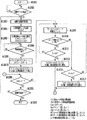
図10は本実施例における画像形成装置の動作を説明するフローチャートである。まず、ステップS1001からステップS1007までは第1の実施例におけるステップS601〜607と同様の動作を行う。 FIG. 10 is a flowchart for explaining the operation of the image forming apparatus in this embodiment. First, in steps S1001 to S1007, the same operations as in steps S601 to S607 in the first embodiment are performed.
次いで、ステップS10072では定着駆動モータ204の目標速度を下記、式5に基づいて図示しないタイマに基づいて時間N1毎に決定し、目標速度を切り換える。
V=V−(Vref−Vd)/(L1/2)(但しL1>0)・・・・・(式5)
本実施例では、一例として、Vd=0.95×Vref、L1=10とすると、(Vref−Vd)/(L1/2)=0.01×Vrefとなり、プロセス速度からプロセス速度の95%の速度まで時間N1毎に1%ずつ目標速度を下げていく。
Next, in step S10072, the target speed of the fixing
V = V− (Vref−Vd) / (L1 / 2) (where L1> 0) (Equation 5)
In this embodiment, as an example, when Vd = 0.95 × Vref and L1 = 10, (Vref−Vd) / (L1 / 2) = 0.01 × Vref, which is 95% of the process speed from the process speed. The target speed is decreased by 1% every time N1 until the speed.
その後、ステップS1008からステップS1011までは第1の実施例におけるステップS608〜611と同様の動作を行う。 Thereafter, operations from step S1008 to step S1011 are the same as those in steps S608 to S611 in the first embodiment.
ステップS1012ではループ検知センサ112の出力信号が“ON”でかつ、現在の定着駆動モータ204の目標速度がVdである場合(ステップS1011でYES)、定着駆動モータ204の目標速度を下記、式3に基づいて図示しないタイマに基づいてN1毎に決定し、目標速度を切り換える。
V=(Vu−Vd)/L1+V(但しL1>0)・・・・・(式3)
ここでL1は中間目標速度数であり、任意に設定される。本実施例では、一例として、Vu=1.05×Vref、Vd=0.95×Vref、L1=10とすると、(Vu−Vd)/L1=0.01×Vrefとなり、プロセス速度の95%の速度からプロセス速度の105%の速度まで時間N1毎に1%ずつ目標速度を上げていく。
In step S1012, if the output signal of the
V = (Vu−Vd) / L1 + V (where L1> 0) (Equation 3)
Here, L1 is an intermediate target speed number, and is arbitrarily set. In this embodiment, as an example, if Vu = 1.05 × Vref, Vd = 0.95 × Vref, and L1 = 10, then (Vu−Vd) /L1=0.01×Vref, which is 95% of the process speed. The target speed is increased by 1% every time N1 from the speed of 105 to the speed of 105% of the process speed.
その後、ステップS1016は第1の実施例におけるステップS616と同様の動作を行う。 Thereafter, step S1016 performs the same operation as step S616 in the first embodiment.
ステップS1017ではループ検知センサ112の出力信号が“ON”でかつ、現在の定着駆動モータ204の目標速度がVuである場合(ステップS1016でYES)、定着駆動モータ204の目標速度を下記、式4に基づいてCPU管理下のタイマに基づいてN1毎に決定し、目標速度を切り換える。
V=V−(Vu−Vd)/L1(但しL1>0)・・・・・(式4)
本実施例では、一例として、Vu=1.05×Vref、Vd=0.95×Vref、L1=10とすると、(Vu−Vd)/L1=0.01×Vrefとなり、プロセス速度の105%の速度からプロセス速度の95%の速度まで時間N1毎に1%ずつ目標速度を下げていく。
In step S1017, when the output signal of the
V = V− (Vu−Vd) / L1 (where L1> 0) (Equation 4)
In this embodiment, as an example, if Vu = 1.05 × Vref, Vd = 0.95 × Vref, and L1 = 10, then (Vu−Vd) /L1=0.01×Vref, which is 105% of the process speed. The target speed is decreased by 1% every time N1 from the speed of 95 to 95% of the process speed.
その後、ステップS1021からステップS1022までは第1の実施例におけるステップS621〜622と同様の動作を行う。 Thereafter, from step S1021 to step S1022, operations similar to those in steps S621 to 622 in the first embodiment are performed.
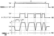
図1は本実施例におけるループを一定量に保持するよう定着駆動モータを制御した場合のタイミングチャートである。用紙検知センサ113が用紙を検知すると用紙のループはまだ形成されていない状態の為、定着駆動モータ204の目標速度を基準速度Vrefからモータ速度切り換え時間N1毎に中間目標速度数L1/2分だけ、切り換えて基準値より遅い値Vdに設定する。Vdで定着駆動モータ204を駆動中、ループ検知センサが“ON”を検知すると、目標速度をVdから複数の中間速度で時間N1毎に加速し、Vuに切り換える。本実施例の一例では、プロセス速度の95%からプロセス速度の105%まで10ステップに分けて、時間N1毎に1%ずつ定着駆動モータ204の目標速度を上げていく。Vuで定着駆動モータ204を駆動中、ループ検知センサが“OFF”を検知すると、目標速度をVuから複数の中間速度で時間N1毎に減速し、Vdに切り換える。本実施の一例では、プロセス速度の105%からプロセス速度の95%まで10ステップに分けて、時間N1毎に1%ずつ定着駆動モータ204の目標速度を下げていく。
FIG. 1 is a timing chart when the fixing drive motor is controlled so as to hold the loop in a constant amount in this embodiment. When the
以上のように、定着駆動モータの目標速度切り換え時に、現状の速度から目標速度までの間を複数の中間速度で加速又は減速することで、急激な速度変動が効果的に抑えられて、定着駆動モータの振動が抑えられるので、より低騒音でかつ画像不良の発生しない高精度な画像形成装置を提供することができる。 As described above, when the target speed of the fixing drive motor is switched, acceleration between the current speed and the target speed is accelerated or decelerated at a plurality of intermediate speeds, so that rapid speed fluctuations can be effectively suppressed and fixing driving can be performed. Since the vibration of the motor is suppressed, it is possible to provide a highly accurate image forming apparatus with lower noise and no image defects.
(第4の実施例)
第1及び第2及び第3の実施例と異なる点のみ説明する。図11、図14、図3の構成は第1の実施例と同様である。
(Fourth embodiment)
Only differences from the first, second, and third embodiments will be described. The configurations of FIGS. 11, 14 and 3 are the same as those of the first embodiment.
第1及び第2及び第3の実施例において定着駆動モータの目標速度切り換え時間を一意としていたが、本実施例では加速時及び減速時で定着駆動モータの目標速度切り換え間隔を異ならせることを特徴とする。 In the first, second, and third embodiments, the target speed switching time of the fixing drive motor is made unique, but in this embodiment, the target speed switching interval of the fixing drive motor is made different during acceleration and deceleration. And
図12は本実施例における画像形成装置の動作を説明するフローチャートである。まず、ステップS1201からステップS1207までは第1の実施例におけるステップS601〜607と同様の動作を行う。 FIG. 12 is a flowchart for explaining the operation of the image forming apparatus in this embodiment. First, from step S1201 to step S1207, operations similar to those in steps S601 to S607 in the first embodiment are performed.
ステップS12072では定着駆動モータ204の目標速度を下記、式6に基づいてCPU管理下のタイマに基づいてN2毎に決定し、目標速度を切り換える。
V=V−(Vref−Vd)/(L1/2)(但しL1>0)・・・・・(式6)
ここでN2は定着駆動モータ204の目標速度減速切り換え時間であり、N2>0の範囲内で任意に決定する。
In step S12072, the target speed of the fixing
V = V− (Vref−Vd) / (L1 / 2) (where L1> 0) (Equation 6)
Here, N2 is a target speed deceleration switching time of the fixing
本実施例では、一例として、Vd=0.95×Vref、L1=10とすると、(Vref−Vd)/(L1/2)=0.01×Vrefとなり、プロセス速度からプロセス速度の95%の速度まで時間N2毎に1%ずつ目標速度を下げていく。 In this embodiment, as an example, when Vd = 0.95 × Vref and L1 = 10, (Vref−Vd) / (L1 / 2) = 0.01 × Vref, which is 95% of the process speed from the process speed. The target speed is decreased by 1% every time N2 until the speed.
その後、ステップS1208からステップS1211までは第1の実施例におけるステップS608〜611と同様の動作を行う。 Thereafter, from step S1208 to step S1211, the same operation as that of steps S608 to 611 in the first embodiment is performed.
ステップS1212ではループ検知センサ112の出力信号が“ON”でかつ、現在の定着駆動モータ204の目標速度がVdである場合(ステップS1211でYES)、定着駆動モータ204の目標速度を下記、式7に基づいて図示しないタイマに基づいてN3毎に決定し、目標速度を切り換える。
V=(Vu−Vd)/L1+V(但しL1>0)・・・・・(式7)
ここでN3は定着駆動モータ204の目標速度加速切り換え時間であり、N3≠N2かつN3>0の範囲内で任意に決定する(本実施例ではN3>N2である)。本実施例では、一例として、Vu=1.05×Vref、Vd=0.95×Vref、L1=10とすると、(Vu−Vd)/L1=0.01×Vrefとなり、プロセス速度の95%の速度からプロセス速度の105%の速度まで時間N3毎に1%ずつ目標速度を上げていく。
In step S1212, when the output signal of the
V = (Vu−Vd) / L1 + V (where L1> 0) (Equation 7)
Here, N3 is a target speed acceleration switching time of the fixing
その後、ステップS1216は第1の実施例におけるステップS616と同様の動作を行う。 Thereafter, step S1216 performs the same operation as step S616 in the first embodiment.
ステップS1217ではループ検知センサ112の出力信号が“ON”でかつ、現在の定着駆動モータ204の目標速度がVuである場合(ステップS1216でYES)、定着駆動モータ204の目標速度を下記、式8に基づいて図示しないタイマに基づいてN2毎に決定し、目標速度を切り換える。
V=V−(Vu−Vd)/L1(但しL1>0)・・・・・(式8)
本実施例では、一例として、Vu=1.05×Vref、Vd=0.95×Vref、L1=10とすると、(Vu−Vd)/L1=0.01×Vrefとなり、プロセス速度の105%の速度からプロセス速度の95%の速度まで時間N2毎に1%ずつ目標速度を下げていく。
In step S1217, when the output signal of the
V = V− (Vu−Vd) / L1 (where L1> 0) (Equation 8)
In this embodiment, as an example, if Vu = 1.05 × Vref, Vd = 0.95 × Vref, and L1 = 10, then (Vu−Vd) /L1=0.01×Vref, which is 105% of the process speed. The target speed is decreased by 1% every time N2 from the above speed to 95% of the process speed.
その後、ステップS1221からステップS1222までは第1の実施例におけるステップS621〜622と同様の動作を行う。 Thereafter, from step S1221 to step S1222, the same operations as in steps S621 to 622 in the first embodiment are performed.
図13は本実施例におけるループを一定量に保持するよう定着駆動モータを制御した場合のタイミングチャートである。用紙検知センサ113が用紙を検知すると用紙のループはまだ形成されていない状態の為、定着駆動モータ204の目標速度を基準速度Vrefからモータ速度切り換え時間N2毎に中間目標速度数L1/2分だけ、切り換えて基準値より遅い値Vdに設定する。Vdで定着駆動モータ204を駆動中、ループ検知センサが“ON”を検知すると、目標速度をVdから複数の中間速度で時間N3毎に加速し、Vuに切り換える。本実施例の一例では、プロセス速度の95%からプロセス速度の105%まで10ステップに分けて、1%ずつ定着駆動モータ204の目標速度を上げていく。Vuで定着駆動モータ204を駆動中、ループ検知センサが“OFF”を検知すると、目標速度がVuから複数の中間速度で時間N2毎に減速し、Vdに切り換わる。本実施の一例では、プロセス速度の105%からプロセス速度の95%まで10ステップに分けて、時間N2毎に1%ずつ定着駆動モータ204の目標速度を下げていく。
FIG. 13 is a timing chart when the fixing drive motor is controlled so as to hold the loop in a constant amount in this embodiment. When the
以上のように、定着駆動モータの目標速度切り換え時に、現状の速度から目標速度までの間を複数の中間速度で加速又は減速し、加速時及び減速時で定着駆動モータの目標速度切り換え間隔を異ならせることで、用紙特有のループ生成ゲインと解消ゲインに適合した定着駆動モータ制御が可能となり、より低騒音でかつ画像不良の発生しない高精度な画像形成装置を提供することができる。 As described above, when the target speed of the fixing drive motor is switched, the current speed to the target speed is accelerated or decelerated at a plurality of intermediate speeds, and the target speed switching interval of the fixing drive motor is different during acceleration and deceleration. By doing so, it becomes possible to perform fixing drive motor control adapted to the loop generation gain and cancellation gain peculiar to the paper, and it is possible to provide a high-accuracy image forming apparatus with lower noise and no occurrence of image defects.
第1から第4の実施例では潜像形成媒体は感光ドラムとしているが、ベルト状の感光体を懸架し、駆動ローラにて駆動しても良い。 In the first to fourth embodiments, the latent image forming medium is a photosensitive drum, but a belt-like photosensitive member may be suspended and driven by a driving roller.
無端状ベルトは紙搬送ベルトとしているが、中間転写体でも良い。 The endless belt is a paper conveying belt, but may be an intermediate transfer member.
フルカラーのトナー像が転写された用紙が定着ローラに搬送されたか否かの検知を用紙検知センサ113を使用して行っているが、ループ検知センサ112を使用しても良い。この場合、一例として、用紙が定着ローラに搬送されるまでは、定着駆動モータ204の駆動速度は速度基準値よりも遅い速度に設定することで転写−定着間に用紙ループを作成し、ループ検知センサ112の出力信号が切り替わったことで用紙通過を判断する。
Although the
中間目標速度数を一意としているが、加速時及び減速時で可変としても良い。 Although the intermediate target speed number is unique, it may be variable during acceleration and deceleration.
速度基準値は画像形成装置の環境温度、湿度に応じて可変としても良い。また、ループ検知センサの出力に基づいて速度基準値を決定する構成であっても良い。 The speed reference value may be variable according to the environmental temperature and humidity of the image forming apparatus. Moreover, the structure which determines a speed reference value based on the output of a loop detection sensor may be sufficient.
101C、101M、101Y、101Bk レーザスキャナ
102C、102M、102Y、102Bk 現像器
103C、103M、103Y、103Bk 感光ドラム
104C、104M、104Y、104Bk 現像ローラ
105C、105M、105Y、105Bk 転写ローラ
106 紙搬送ベルト
107 ベルト駆動ローラ
108 ベルト従動ローラ
110 定着ローラ
111 加圧ローラ
112 ループ検知センサ
113 用紙検知センサ
201 CPU
202 モータドライバ
203 現像カートリッジ駆動モータ
204 定着駆動モータ
301 フォトインタラプタ
101C, 101M, 101Y,
202
Claims (1)
前記転写手段によって記録材に転写された画像を該記録材に定着する定着手段と、
前記転写手段と前記定着手段によって記録材を搬送する際に、該記録材に発生したたわみを検出する検出手段と、
前記検出手段によって前記たわみを検知すると、前記定着手段によって記録材を搬送する搬送速度を基準速度より速い第1の目標速度に切り換え、前記検出手段によって前記たわみを検出しなくなると、前記基準速度より遅い第2の目標速度に切り換えて、前記転写手段と前記定着手段との間で記録材に発生するたわみの量を制御し、前記搬送速度を前記第1の目標速度から前記第2の目標速度に切り換えるまでの第1切り換え期間において、前記搬送速度を前記第1の目標速度より遅く、かつ、前記第2の目標速度より速い複数の中間速度で段階的に切り換え、かつ、前記搬送速度を前記第2の目標速度から前記第1の目標速度に切り換えるまでの第2切り換え期間において、前記搬送速度を前記複数の中間速度で段階的に切り換える制御手段と、
を備え、
前記制御手段は、前記第2切り替え期間が前記第1切り換え期間よりも長くなるように前記複数の中間速度の切り替えを制御する
ことを特徴とする画像形成装置。 Transfer means for transferring an image to a recording material;
Fixing means for fixing the image transferred to the recording material by the transfer means to the recording material;
Detecting means for detecting deflection generated in the recording material when the recording material is conveyed by the transfer means and the fixing means;
When the deflection is detected by the detection unit, the conveyance speed at which the recording material is conveyed by the fixing unit is switched to a first target speed that is faster than a reference speed, and when the deflection is not detected by the detection unit, the reference speed is exceeded. By switching to a slow second target speed, the amount of deflection generated in the recording material between the transfer means and the fixing means is controlled, and the transport speed is changed from the first target speed to the second target speed. in the first switching period until switching to, the conveying speed slower than the first target speed, and stepwise switching by the second fast plurality of intermediate speed than the target speed of, and the said transport speed in the second of the second switching period from the target speed to switch to the first target speed, stepwise switches controlling the transport speed at said plurality of intermediate speed And the stage,
With
The image forming apparatus, wherein the control unit controls switching of the plurality of intermediate speeds so that the second switching period is longer than the first switching period .
Priority Applications (1)
| Application Number | Priority Date | Filing Date | Title |
|---|---|---|---|
| JP2005224444A JP4822762B2 (en) | 2005-08-02 | 2005-08-02 | Image forming apparatus |
Applications Claiming Priority (1)
| Application Number | Priority Date | Filing Date | Title |
|---|---|---|---|
| JP2005224444A JP4822762B2 (en) | 2005-08-02 | 2005-08-02 | Image forming apparatus |
Publications (3)
| Publication Number | Publication Date |
|---|---|
| JP2007041224A JP2007041224A (en) | 2007-02-15 |
| JP2007041224A5 JP2007041224A5 (en) | 2010-05-06 |
| JP4822762B2 true JP4822762B2 (en) | 2011-11-24 |
Family
ID=37799273
Family Applications (1)
| Application Number | Title | Priority Date | Filing Date |
|---|---|---|---|
| JP2005224444A Expired - Fee Related JP4822762B2 (en) | 2005-08-02 | 2005-08-02 | Image forming apparatus |
Country Status (1)
| Country | Link |
|---|---|
| JP (1) | JP4822762B2 (en) |
Families Citing this family (4)
| Publication number | Priority date | Publication date | Assignee | Title |
|---|---|---|---|---|
| JP5087948B2 (en) * | 2007-02-26 | 2012-12-05 | コニカミノルタビジネステクノロジーズ株式会社 | Image forming apparatus capable of duplex recording |
| JP5845572B2 (en) * | 2010-01-19 | 2016-01-20 | 株式会社リコー | Image forming apparatus, image forming program, and recording medium |
| JP5367676B2 (en) * | 2010-11-10 | 2013-12-11 | 株式会社沖データ | Image forming apparatus |
| JP2018072769A (en) * | 2016-11-04 | 2018-05-10 | シャープ株式会社 | Image forming apparatus |
Family Cites Families (2)
| Publication number | Priority date | Publication date | Assignee | Title |
|---|---|---|---|---|
| JPH1097154A (en) * | 1996-09-19 | 1998-04-14 | Canon Inc | Image forming device |
| JP2003345150A (en) * | 2002-05-30 | 2003-12-03 | Canon Inc | Image forming apparatus |
-
2005
- 2005-08-02 JP JP2005224444A patent/JP4822762B2/en not_active Expired - Fee Related
Also Published As
| Publication number | Publication date |
|---|---|
| JP2007041224A (en) | 2007-02-15 |
Similar Documents
| Publication | Publication Date | Title |
|---|---|---|
| JP4725607B2 (en) | Image forming apparatus, control apparatus, and program | |
| JP5900775B2 (en) | Image forming apparatus | |
| JP2009057169A (en) | Paper discharge control device, and image forming device | |
| CN107065472B (en) | Image forming apparatus | |
| JP2008268851A (en) | Image forming apparatus | |
| JP2008158076A (en) | Sheet conveying controller of image forming apparatus | |
| JP4822762B2 (en) | Image forming apparatus | |
| JP2008214103A (en) | Image forming apparatus and method for controlling feeding of sheet | |
| JP2007017538A (en) | Image forming apparatus and its control method | |
| JP2010054819A (en) | Color image forming apparatus | |
| JP4878497B2 (en) | Image forming apparatus | |
| JP4756934B2 (en) | Image forming apparatus | |
| JP6752621B2 (en) | Image forming device | |
| US7900918B2 (en) | Sheet conveying system, as well as image forming apparatus and sheet conveying apparatus thereof | |
| JP4923479B2 (en) | Image forming apparatus | |
| US10534302B2 (en) | Image forming apparatus | |
| JP5177622B2 (en) | Image forming apparatus | |
| JP6109363B2 (en) | Image forming apparatus | |
| JP2005181507A (en) | Image forming apparatus and speed control method therefor | |
| JP6472276B2 (en) | Image forming apparatus | |
| US6801725B2 (en) | Image forming apparatus | |
| JP2005172435A (en) | Sheet metal discrimination device, image forming device provided therewith, and sheet material discrimination method | |
| JP2012108241A (en) | Image forming apparatus | |
| JP2007310077A (en) | Image forming apparatus | |
| JP2008230807A (en) | Image forming device and control method therefor |
Legal Events
| Date | Code | Title | Description |
|---|---|---|---|
| A521 | Request for written amendment filed |
Free format text: JAPANESE INTERMEDIATE CODE: A523 Effective date: 20080804 |
|
| A621 | Written request for application examination |
Free format text: JAPANESE INTERMEDIATE CODE: A621 Effective date: 20080804 |
|
| A521 | Request for written amendment filed |
Free format text: JAPANESE INTERMEDIATE CODE: A523 Effective date: 20100324 |
|
| A131 | Notification of reasons for refusal |
Free format text: JAPANESE INTERMEDIATE CODE: A131 Effective date: 20100827 |
|
| A521 | Request for written amendment filed |
Free format text: JAPANESE INTERMEDIATE CODE: A523 Effective date: 20101026 |
|
| RD02 | Notification of acceptance of power of attorney |
Free format text: JAPANESE INTERMEDIATE CODE: A7422 Effective date: 20101106 |
|
| A131 | Notification of reasons for refusal |
Free format text: JAPANESE INTERMEDIATE CODE: A131 Effective date: 20110304 |
|
| A521 | Request for written amendment filed |
Free format text: JAPANESE INTERMEDIATE CODE: A523 Effective date: 20110502 |
|
| TRDD | Decision of grant or rejection written | ||
| A01 | Written decision to grant a patent or to grant a registration (utility model) |
Free format text: JAPANESE INTERMEDIATE CODE: A01 Effective date: 20110902 |
|
| A01 | Written decision to grant a patent or to grant a registration (utility model) |
Free format text: JAPANESE INTERMEDIATE CODE: A01 |
|
| A61 | First payment of annual fees (during grant procedure) |
Free format text: JAPANESE INTERMEDIATE CODE: A61 Effective date: 20110906 |
|
| R151 | Written notification of patent or utility model registration |
Ref document number: 4822762 Country of ref document: JP Free format text: JAPANESE INTERMEDIATE CODE: R151 |
|
| FPAY | Renewal fee payment (event date is renewal date of database) |
Free format text: PAYMENT UNTIL: 20140916 Year of fee payment: 3 |
|
| LAPS | Cancellation because of no payment of annual fees |