JP4820765B2 - Variable turbocharger - Google Patents
Variable turbocharger Download PDFInfo
- Publication number
- JP4820765B2 JP4820765B2 JP2007021893A JP2007021893A JP4820765B2 JP 4820765 B2 JP4820765 B2 JP 4820765B2 JP 2007021893 A JP2007021893 A JP 2007021893A JP 2007021893 A JP2007021893 A JP 2007021893A JP 4820765 B2 JP4820765 B2 JP 4820765B2
- Authority
- JP
- Japan
- Prior art keywords
- drive device
- oil
- variable turbocharger
- drive shaft
- piston
- Prior art date
- Legal status (The legal status is an assumption and is not a legal conclusion. Google has not performed a legal analysis and makes no representation as to the accuracy of the status listed.)
- Expired - Fee Related
Links
Images


Classifications
-
- F—MECHANICAL ENGINEERING; LIGHTING; HEATING; WEAPONS; BLASTING
- F02—COMBUSTION ENGINES; HOT-GAS OR COMBUSTION-PRODUCT ENGINE PLANTS
- F02C—GAS-TURBINE PLANTS; AIR INTAKES FOR JET-PROPULSION PLANTS; CONTROLLING FUEL SUPPLY IN AIR-BREATHING JET-PROPULSION PLANTS
- F02C6/00—Plural gas-turbine plants; Combinations of gas-turbine plants with other apparatus; Adaptations of gas- turbine plants for special use
- F02C6/04—Gas-turbine plants providing heated or pressurised working fluid for other apparatus, e.g. without mechanical power output
- F02C6/10—Gas-turbine plants providing heated or pressurised working fluid for other apparatus, e.g. without mechanical power output supplying working fluid to a user, e.g. a chemical process, which returns working fluid to a turbine of the plant
- F02C6/12—Turbochargers, i.e. plants for augmenting mechanical power output of internal-combustion piston engines by increase of charge pressure
-
- F—MECHANICAL ENGINEERING; LIGHTING; HEATING; WEAPONS; BLASTING
- F01—MACHINES OR ENGINES IN GENERAL; ENGINE PLANTS IN GENERAL; STEAM ENGINES
- F01D—NON-POSITIVE DISPLACEMENT MACHINES OR ENGINES, e.g. STEAM TURBINES
- F01D17/00—Regulating or controlling by varying flow
- F01D17/10—Final actuators
- F01D17/12—Final actuators arranged in stator parts
- F01D17/14—Final actuators arranged in stator parts varying effective cross-sectional area of nozzles or guide conduits
- F01D17/141—Final actuators arranged in stator parts varying effective cross-sectional area of nozzles or guide conduits by means of shiftable members or valves obturating part of the flow path
- F01D17/143—Final actuators arranged in stator parts varying effective cross-sectional area of nozzles or guide conduits by means of shiftable members or valves obturating part of the flow path the shiftable member being a wall, or part thereof of a radial diffuser
-
- F—MECHANICAL ENGINEERING; LIGHTING; HEATING; WEAPONS; BLASTING
- F05—INDEXING SCHEMES RELATING TO ENGINES OR PUMPS IN VARIOUS SUBCLASSES OF CLASSES F01-F04
- F05D—INDEXING SCHEME FOR ASPECTS RELATING TO NON-POSITIVE-DISPLACEMENT MACHINES OR ENGINES, GAS-TURBINES OR JET-PROPULSION PLANTS
- F05D2220/00—Application
- F05D2220/40—Application in turbochargers
Description
本発明は、可変ターボ過給機に係り、特に可変ターボを駆動するアクチュエータの取付構造に関する。 The present invention relates to a variable turbocharger, and more particularly to an attachment structure for an actuator that drives a variable turbo.
従来、排気ガスを排気タービンに噴出させるノズル部の開口面積を調整できるようにした可変ターボ過給機が知られている(特許文献1)。この可変ターボ過給機によれば、排気ガス量が少ないエンジンの低速回転域では、ノズル部を形成している排気導入壁間の隙間を狭めて開口面積を小さくすればよく、こうすることで排気タービンに流入する排気ガスの流速が増加するため、タービンホイールの回転エネルギが大きくなり、給気コンプレッサの過給能力を上げることができる。 2. Description of the Related Art Conventionally, there is known a variable turbocharger that can adjust an opening area of a nozzle portion that ejects exhaust gas to an exhaust turbine (Patent Document 1). According to this variable turbocharger, in the low-speed rotation region of an engine with a small amount of exhaust gas, the opening area can be reduced by narrowing the gap between the exhaust introduction walls forming the nozzle portion. Since the flow velocity of the exhaust gas flowing into the exhaust turbine increases, the rotational energy of the turbine wheel increases, and the supercharging capability of the air supply compressor can be increased.
一方、可変ターボ過給機に限らず、ターボ過給機を用いることにより、排気管や吸気管の取り回しが複雑になることが知られている(特許文献2)。図11は、特許文献2に示されたターボ過給機付きエンジンの斜視図である。この図では、大小二つのターボ過給機140,141が用いられているが、ターボ過給機が一つの場合でも複雑になることに違いはない。
On the other hand, it is known that not only the variable turbocharger but also the use of a turbocharger complicates the handling of the exhaust pipe and the intake pipe (Patent Document 2). FIG. 11 is a perspective view of an engine with a turbocharger disclosed in
特にターボ過給機として可変ターボ過給機を用いた場合には、可変ターボ過給機内部にノズル部の開口面積を調整する調整機構が設けられるとともに、この調整機構を駆動する駆動装置が必要となるが、このような駆動装置は、可変ター過給機を構成するハウジングの外側にボルト等により取り付けられるため、他の部品との配置スペースの取り合いが生じ、部品配置がさらに複雑化する。しかも、図11に示すように、EGR(Exhaust Gas Recirculation)装置142が設けられている場合には、排気ガスの一部を排気管から吸気管に戻すためのEGR配管143や、EGRバルブ144、EGRクーラ145等が設けられるため、さらに複雑になる。
Especially when a variable turbocharger is used as a turbocharger, an adjustment mechanism for adjusting the opening area of the nozzle portion is provided inside the variable turbocharger, and a drive device for driving the adjustment mechanism is required. However, since such a drive device is attached to the outside of the housing constituting the variable turbocharger by means of bolts or the like, the arrangement space with other parts is generated, and the arrangement of the parts is further complicated. In addition, as shown in FIG. 11, when an EGR (Exhaust Gas Recirculation)
ところで、同じ容量の可変ターボ過給機を用いる場合でも、エンジンの仕様や、エンジンが搭載される車両の仕様によっては、エンジン周りの配管の取り回しなど、部品の配置を異ならせることがあり、これに伴ってエンジン本体に対する可変ターボ過給機の取付方向、あるいは取付位置を異ならせることがある。特にエンジンに対する可変ターボ過給機の向きが逆転する場合には、可変ターボ過給機でのハウジングに対する駆動装置の取付位置が一様であると、他部品との干渉あるいは排気マニホールド等からの放熱の影響を受けるという問題がある。従って、可変ターボ過給機としては、ハウジングに対する駆動装置の取付位置等も各仕様に応じて変更する必要が生じる。 By the way, even when using a variable turbocharger with the same capacity, depending on the engine specifications and the specifications of the vehicle on which the engine is mounted, the arrangement of parts, such as the routing of piping around the engine, may vary. As a result, the mounting direction or mounting position of the variable turbocharger with respect to the engine body may be varied. In particular, when the direction of the variable turbocharger with respect to the engine is reversed, if the mounting position of the drive device with respect to the housing in the variable turbocharger is uniform, it will interfere with other parts or dissipate heat from the exhaust manifold. There is a problem of being affected. Therefore, for the variable turbocharger, it is necessary to change the mounting position of the drive device with respect to the housing according to each specification.
しかしながら、ハウジングに対する駆動装置の取付位置が異なる可変ターボ過給機を各仕様に合わせて専用に設計していたのでは、可変ターボ過給機としての種類が増えるうえ、ハウジングなどの部品としても各仕様に応じたものを複数種類用意する必要があり、可変ターボ過給機を製造するうえで部品管理が煩雑になる。 However, if a variable turbocharger with a different mounting position of the drive unit relative to the housing was designed exclusively for each specification, the number of types of variable turbochargers increased, and each component such as a housing It is necessary to prepare a plurality of types according to the specifications, and parts management becomes complicated when manufacturing a variable turbocharger.
本発明の目的は、異なる取付形態に容易に対応でき、かつ部品管理の煩雑化を防止できる可変ターボ過給機を提供することにある。 An object of the present invention is to provide a variable turbocharger that can easily cope with different mounting forms and can prevent complication of parts management.
本発明の請求項1に係る可変ターボ過給機は、ターボシャフトを支持するセンターハウジングを有するとともに、ノズル開度を調整するノズル開度調整機構と、このノズル開度調整機構の駆動シャフトを駆動する駆動装置とを備え、前記センターハウジングは、前記ターボシャフトを挟んだ対向位置に設けられて、前記駆動装置全体が該ターボシャフトの軸線を中心として線対称となるように取り付けられる一対の取付面と、これらの取付面を貫通しかつ前記駆動シャフトが挿通される挿通孔とを備え、前記駆動装置は、前記一対の取付面のうちのいずれか一方に取り付けられていることを特徴とする。 A variable turbocharger according to a first aspect of the present invention includes a center housing that supports a turbo shaft, a nozzle opening adjusting mechanism that adjusts the nozzle opening, and a drive shaft of the nozzle opening adjusting mechanism. and a drive device for the center housing, the provided sandwiched position facing the turboshaft, a pair of mounting surfaces mounted so as to be axisymmetrical about the axis of the entire driving apparatus is the turboshaft And an insertion hole that passes through these attachment surfaces and through which the drive shaft is inserted, and the drive device is attached to one of the pair of attachment surfaces.
本発明の請求項2に係る可変ターボ過給機は、請求項1に記載の可変ターボ過給機において、前記挿通孔の両側には、前記駆動シャフトが挿通されるブッシュがそれぞれ設けられ、前記各取付面からこれと近接する前記ブッシュの外方側端部までの組込寸法が同一であることを特徴とする。
The variable turbocharger according to
請求項3に記載の可変ターボ過給機は、請求項1または請求項2に記載の可変ターボ過給機において、前記ノズル開度調整機構はリンク機構で構成され、前記駆動装置は油圧サーボ駆動装置であることを特徴とする。 A variable turbocharger according to a third aspect is the variable turbocharger according to the first or second aspect, wherein the nozzle opening adjustment mechanism is a link mechanism, and the drive device is a hydraulic servo drive. It is a device.
以上において、請求項1の発明によれば、センターハウジングの互いに対向する側に駆動装置の取付面をそれぞれ設けるので、エンジンの仕様等によって可変ターボ過給機の位置や向きが変わっても、エンジン周りの部品との取り合いを考慮して優位な側の取付面を選択でき、駆動装置をターボ本体に容易に取り付けることができる。また、駆動装置をいずれの取付面側に取り付ける場合でも、これによって駆動される駆動シャフト等の部品を共通して用いる構成とすることにより、部品の種類が増加する心配がなく、部品管理の煩雑化を招くおそれがない。 In the above, according to the first aspect of the present invention, since the mounting surfaces of the drive device are provided on the opposite sides of the center housing, even if the position or orientation of the variable turbocharger changes depending on the engine specifications, the engine The mounting surface on the superior side can be selected in consideration of the connection with the surrounding parts, and the drive device can be easily mounted on the turbo body. Moreover, even when the drive device is mounted on any mounting surface side, by using a configuration in which components such as a drive shaft driven by the drive device are used in common, there is no fear of increasing the types of components, and complicated component management is required. There is no risk of instability.
請求項2の発明によれば、センターハウジングの挿通孔内には予め、一対のブッシュを各取付面から同じ組込寸法でそれぞれ配置しておくので、駆動装置の取付位置に合わせて駆動シャフトをいずれの側から挿通させた場合でも、駆動シャフトを各ブッシュで確実に支持できる。 According to the second aspect of the present invention, since the pair of bushes are arranged in advance in the insertion hole of the center housing with the same mounting dimension from each mounting surface, the drive shaft is fitted in accordance with the mounting position of the driving device. The drive shaft can be reliably supported by each bush even when inserted from either side.
請求項3の発明によれば、リンク機構で構成されたノズル開度調整機構を油圧サーボ駆動装置により油圧駆動するので、より大きな駆動力で、かつ緻密に駆動できる。従って、リンク機構中のレバーとして機能する部品の長さを短くしても、ノズル開度調整機構を確実に駆動でき、部品を短くすることでノズル開度調整機構、ひいては可変ターボ過給機を小型化できる。 According to the third aspect of the present invention, since the nozzle opening degree adjusting mechanism constituted by the link mechanism is hydraulically driven by the hydraulic servo drive device, it can be driven more precisely with a larger driving force. Therefore, even if the length of the part functioning as a lever in the link mechanism is shortened, the nozzle opening degree adjusting mechanism can be driven reliably, and by shortening the part, the nozzle opening degree adjusting mechanism and thus the variable turbocharger can be driven. Can be downsized.
以下、本発明の一実施形態を図面に基づいて説明する。
図1は、本実施形態に係る可変ターボ過給機1の断面図である。図2および図3は、図1のII−II線断面図およびIII−III線断面図。図4は、図3のIV−IV線断面図である。可変ターボ過給機1が搭載されるエンジンとしては、その図示を省略するが、複雑な部品配置を伴うEGR装置付のエンジンを想定している。
Hereinafter, an embodiment of the present invention will be described with reference to the drawings.
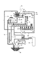
FIG. 1 is a cross-sectional view of a
図1において、可変ターボ過給機1は、図中の右側にタービンを備え、左側にコンプレッサを備えた構成であり、図示略のエンジン本体に設けられている。タービン側のタービンハウジング2内にはタービンホイール3が収容され、コンプレッサ側のコンプレッサハウジング4内にはコンプレッサインペラ5が収容されている。タービンホイール3にはターボシャフト6が一体に設けられ、ターボシャフト6の先端にコンプレッサインペラ5が取り付けられている。このため、排気ガスによって回転するタービンホイール3の回転が、ターボシャフト6を介してコンプレッサインペラ5に伝達され、コンプレッサインペラ5の回転によって吸気が圧縮過給される。
In FIG. 1, the
タービンハウジング2には、エンジン本体からの排気ガスを導入するボリュート状の排気導入路10が設けられている。排気導入路10には、排気ガスをタービンホイール3側に噴出するためのノズル部11が周方向に連続して設けられており、ノズル部11から噴出した排気ガスがタービンホイール3を回転させた後に排気出口12から排気される。ノズル部11は、互いに対向する一対の排気導入壁13,14によって形成されている。
The
一方の排気導入壁13は、断面コ字形で環状とされた可動リング15の側面16によって形成されている。可動リング15は、センターハウジング7に設けられた環状の収容部8内に収容されている。可動リング15の側面16には、他方の排気導入壁14側に向けて突出した複数のノズルベーン17が等周間隔で取り付けられている。排気導入壁14には、周方向に連続した凹部18が設けられ、この凹部18内に各ノズルベーン17の先端側が収容される。このような構造においては、可動リング15を後述するスライド機構20(図2参照)によって進退させることにより、排気導入壁13を排気導入壁14に対して近接離間させ、ノズル部11の開口面積を変更する。
One
センターハウジング7の内部には、ターボシャフト6を支持する軸受部110が設けられており、この軸受部110内にターボシャフト6がジャーナルベアリング111を介して挿通支持されている。また、軸受部110の図中上方には、エンジン本体側からの油を取り入れる油流入部112が設けられている。油流入部112に流入した油は、センターハウジング7内の内部流路113を通して、その一部がさらに分岐流路114から軸受部110内に供給され、ターボシャフト6の回転部分が潤滑され、軸受部110の流出部116からセンターハウジング7内の油戻し室117に流れ落ちる。他の一部は、コンプレッサ側のスラストベアリング115部分を潤滑した後、そのまま下方の油戻し室117に流れ落ちる。そして、油戻し室117に流れ落ちた油は、センターハウジング7の底部に設けられた戻し口118からエンジン本体にドレインされる。
A bearing portion 110 that supports the
なお、コンプレッサ側の構成は、通常のターボ過給機と同じであり、公知であるため、ここでの詳細な説明を省略する。以下には、ノズル開度調整機構としてのスライド機構20について詳説する。
The configuration on the compressor side is the same as that of a normal turbocharger, and is well known, so detailed description thereof is omitted here. Hereinafter, the
スライド機構20は、センターハウジング7の下部側に挿通された駆動シャフト21を回動駆動することで、前述の可動リング15を進退させる構造である。図2〜図4には、そのようなスライド機構20の要部が示されている。図2〜図4において、駆動シャフト21の途中位置には、上方に向かって円弧状に延設されたヨーク22(図3参照)がボルト22Aにて固定されている。ヨーク22の両端には、水平方向外側に突出したピン23が取り付けられ、このピン23にはスライダ24が嵌め込まれている。スライダ24は、前述のターボシャフト6と平行な支持ロッド25の基端側の摺動溝26に摺動自在に嵌合している。支持ロッド25の先端は可動リング15の裏面側に固定されている。
The
従って、駆動シャフト21を回動させると、ヨーク22がターボシャフト6の軸方向に沿って揺動し、よって支持ロッド25が移動して可動リング15を動かし、一方の排気導入壁13が他方の排気導入壁14に対して進退することになる。このようなスライド機構20においては、ヨーク22、ピン23、スライダ24、および摺動溝26を有した支持ロッド25が、駆動シャフト21の回動運動を排気導入壁13の進退運動に変換する変換手段を構成している。
Therefore, when the
スライド機構20の駆動シャフト21は、その端部に設けられたレバー27を介して油圧サーボ駆動装置30によって回動駆動される。以下には、油圧サーボ駆動装置30について詳説する。
The
図3〜図5に示すように、油圧サーボ駆動装置30は基本的に、サーボピストン31を上下に進退運動させることで駆動シャフト21を回動させる構造である。このためにサーボピストン31の外周には、軸方向に対して直交した摺動溝32が設けられ、駆動シャフト21側のレバー27には、摺動溝32側に突出したピン28が設けられ、このピン28にスライダ29が嵌め込まれ、スライダ29が前記摺動溝32に摺動自在に嵌合している。
As shown in FIGS. 3 to 5, the hydraulic
つまり、本実施形態では、摺動溝32、スライダ29、ピン28、レバー27を含んで、サーボピストン31の進退運動を駆動シャフト21の回動運動に変換する別の変換手段が構成されている。サーボピストン31を上下動させると、それに伴ってスライダ29が上下動するとともに摺動溝32に沿って摺動し、このスライダ29の動きとピン28の回動とによりレバー27の円弧動を許容し、レバー27を回動させることが可能である。
That is, in the present embodiment, another conversion means that includes the sliding
そして、この変換手段およびセンターハウジング7内の前述の変換手段は共にリンク機構であり、スライド調整機構20全体がリンク機構で構成されていることになる。このようなリンク機構は、圧油で作動する油圧サーボ駆動装置30の大きな駆動力で駆動されることから、リンク機構中のレバー27の長さや、ヨーク22の腕部分の長さを短くしても、スライド機構20を確実に駆動させることができ、スライド機構20をコンパクトにできて可変ターボ過給機1の小型化を促進できる。
The conversion means and the conversion means in the
ここで、駆動シャフト21のレバー27側は、油圧サーボ駆動装置30のハウジング33内に設けられた油溜室33B内に収容されている。この油溜室33Bは、サーボピストン31の動作に使用された圧油が排出されて溜まる部屋であって、サーボピストン31の外周を所定幅で取り巻くように、ハウジング33の周方向に連続して形成されている。
Here, the
この油溜室33Bとセンターハウジング7内の油戻し室117とは、センターハウジング7に穿設されたドレイン流路7Aで連通している。つまり、ドレイン流路7Aの一端側は油溜室33Bに開口し、他端側は油戻し室117に開口している。従って、油溜室33Bに流れ出した圧油は、ドレイン流路7Aを通してセンターハウジング7内に流出し、戻し口118からドレイン回路75(図9参照)を通過してエンジン本体にドレインされるのである。このドレイン流路7Aは、油溜室33Bからの圧油をターボ本体を介して戻すために設けられたものであるが、加工が簡単であり、かつ流路径などの設計上の自由度が大きいというメリットがある。
The
また、油溜室33B内には、開口部33Aを通して駆動シャフト21が入り込んでいる。駆動シャフト21は、センターハウジング7に設けられた挿通孔119に挿通されている。挿通孔119内の両端(図4には一端側のみを図示)にはブッシュ120が配置されており、これらのブッシュ120を貫通した状態で駆動シャフト21の両側が支持されている。ブッシュ120は挿通孔119内に圧入等されているのに対し、ブッシュ120と駆動シャフト21との間には油膜が形成される程度の隙間が存在している。つまり、この隙間が別のドレイン流路21Bとして機能するようになるため、油溜室33Bの圧油がドレイン流路21Bを通してもセンターハウジング7側に流れることになり、駆動シャフト21周りを良好に潤滑できる。
Further, the
図6には、油圧サーボ駆動装置30全体の縦断面が示されている。図6において、油圧サーボ駆動装置30は、前記サーボピストン31と、このサーボピストン31を摺動自在に収容し、かつ一部に開口部33Aを有した前記ハウジング33と、サーボピストン31の軸方向に貫通したセンターホール34内に収容されてパイロット圧によって摺動するパイロットスプール36とを備え、開口部33A周りをシールするOリング100を介して可変ターボ過給機1のセンターハウジング7に取り付けられている。
FIG. 6 shows a longitudinal section of the entire hydraulic
先ず、ハウジング33の内部には、上下に貫通する円筒状のシリンダ35が設けられており、このシリンダ35内にサーボピストン31が収容されている。シリンダ35の上下端側はOリング101,102を介して閉塞部材37,38によって密閉されている。ハウジング33の開口部33Aに対応した位置には、駆動シャフト21とサーボピストン31との連結部39が設けられている。従って、開口部33Aや油溜室33Bの大きさは、サーボピストン31およびスライダ29の摺動量、および排出される圧油の流量等を考慮して設定されている。
First, a
ハウジング33において、開口部33Aとは反対側の側面には、例えば可変ターボ過給機1から離れた位置にある比例電磁弁95(図9)からのパイロット圧を供給するパイロットポート41、昇圧ポンプ92(図9)からの圧油を供給するポンプポート42が設けられている。昇圧ポンプ92および比例電磁弁95は、本実施形態の可変ターボ過給機1が搭載される図示しない同一のエンジン本体に設置されている。
On the side surface of the
ハウジング33のシリンダ35は、サーボピストン31が摺動する部分と、その上方の部分とが仕切部材44によって仕切られている。この仕切部材44は、シリンダ35の内周面に設けられた段差部分に当接しており、当接部分の近傍には、仕切部材44で仕切られた部位をシールするためのOリング103が設けられている。仕切部材44には下方に垂下した筒部45が設けられており、この筒部45がサーボピストン31のセンターホール34の上方側に入り込んでいる。そして、仕切部材44で仕切られた上方の部屋がパイロット油圧室46とされ、このパイロット油圧室46とパイロットポート41とが連通している。
In the
これに対して、仕切部材44で仕切られた下方の部屋は、当該仕切部材44とサーボピストン31の上端面との間に形成される第1油圧室47となっている。つまり、前記パイロット油圧室46は、第1油圧室47に対して軸方向の外側(本実施形態では上側)にずれているのであり、この配置によって油圧サーボ駆動装置30全体が大径化するのを抑制している。さらに、サーボピストン31の下端面と下側の閉塞部材38との間には第2油圧室48が形成されている。
On the other hand, the lower chamber partitioned by the
次に、サーボピストン31について説明する。サーボピストン31には、センターホール34とハウジング33のポンプポート42とを連通させて、ポンプからの圧油をセンターホール34内に流入させるプレッシャポート51が設けられている。このプレッシャポート51の外側は、径方向に対向して形成された溝部分に開口しており、溝部分が所定の上下寸法を有することにより、サーボピストン31のストローク内でプレッシャポート51とポンプポート42とが常時連通することになる。
Next, the
さらに、サーボピストン31には、センターホール34とハウジング33の前記油溜室33Bとを連通させて、センターホール34内の圧油をターボ本体のセンターハウジング7内に流すリターンポート52が設けられている。このリターンポート52の外側は、サーボピストン31の外周に形成された溝部分に開口しており、サーボピストン31のストローク内ではやはりリターンポート52と油溜室33Bとが常時連通する。また、本実施形態では、リターンポート52がサーボピストン31を径方向に貫通して設けられており、ドレインされる圧油の一部がそのまま、スライダ29が嵌め込まれた摺動溝32側から油溜室33Bに流れ出るようになっている。
Further, the
サーボピストン31には加えて、図6中に点線で示すように、センターホール34と上方の第1油圧室47とを連通させる第1ピストンポート53、およびセンターホール34と下方の第2油圧室48とを連通させる第2ピストンポート54が設けられている。この際、第1ピストンポート53のセンターホール34側の開口部分は、プレッシャポート51の開口部分よりも下方に位置し、第2ピストンポート54のセンターホール34側の開口部分は、プレッシャポート51の開口部分よりも上方に位置している。第1、第2ピストンポート53,54はそれぞれ、プレッシャポート51およびリターンポート52に対して連通しない位置にずれて設けられている。
In addition to the
センターホール34の下方側は、当接部材55がサーボピストン31にOリング104を介して螺設されることで密閉されており、当接部材55を介してサーボピストン31が閉塞部材38に当接し、当接した位置がサーボピストン31の最下位置となる。第2油圧室48内において、閉塞部材38と当接部材55との間にはコイルばね56が配置され、サーボピストン31の上方側への移動をアシストしている。昇圧ポンプ92の故障等により、油圧サーボ駆動装置30につながる配管内の圧油がなくなった時でも、コイルばね56のばね力によって可変ターボ過給機1のノズル開度が開き側(好ましくは全開)で維持されるようになっている。
The lower side of the
パイロットスプール36は、略中央部分に2つの第1、第2スプールランド61,62を備えている。パイロットスプール36の内部には、下方に開口したリターン流路63が設けられており、第1スプールランド61の上側の溝部分とリターン流路63とが連通し、第2スプールランド62の下側の溝部分とリターン流路63とが同様に連通している。さらに、リターン流路63の下側が開口していることで、このリターン流路63、リターンポート52、油溜室33Bが連通している。
The
また、パイロットスプール36は、仕切部材44の筒部45を通してサーボピストン31のセンターホール34内を上下に摺動可能であり、その上端部分がパイロット油圧室46内に配置された保持部材64に螺合保持されている。パイロット油圧室46内において、保持部材64はコイルばね65によって上方に付勢されており、コイルばね65の付勢力に抗するパイロット圧によってパイロットスプール36が下方に移動し、パイロット圧油の戻り(ドレイン流路については図示しないが、電磁弁95側でオイルパン80にドレインされる)によりコイルばね65の付勢力で上方へ移動する。
The
このような構成の油圧サーボ駆動装置30では、パイロットスプール36がサーボピストン31に対して上昇すると、それに追従してサーボピストン31も上昇し、パイロットスプール36が下降すると、サーボピストン31も追従して下降する。この際、パイロットスプール36は、サーボピストン31内を軸方向に摺動するだけであるから、可動リング15の進退時の駆動負荷は、スライド機構20を介してサーボピストン31に作用するが、パイロットスプール36には一切作用しない。
In the hydraulic
このため、本実施形態では、パイロットスプール36の位置を制御し、よってサーボピストン31の位置制御を行い、ひいては可動リング15を進退させてノズル部11の開口面積を変えるのであるが、この際、パイロットスプール36の位置制御を駆動負荷に左右されずに行うことができ、負荷ドリフトをなくすことができる。従って、排気ガスによる流体圧が一定していない排気ターボ、つまり本実施形態のような可変ターボ過給機1の場合でも、ノズル部11の開口面積を容易にコントロールでき、エミッションを正確に制御できる。また、位置制御を正確に行えることで、制御方式を例えばフィードバック制御からフィードフォワード制御にして応答時間を短くすることもでき、トランジェントにも精度よく対応できる。
For this reason, in this embodiment, the position of the
次に、図6〜図8を参照し、油圧サーボ駆動装置30の動きについて具体的に説明する。図6では、コイルばね65の付勢力を越えるパイロット圧が供給されることで、パイロットスプール36およびサーボピストン31の両方が共に最下位置にある。従って、この状態においては、パイロットスプール36の下端が当接部材55の上端に当接し、また、当接部材55の下端は閉塞部材38に当接している。さらに、この位置では、パイロットスプール36の上側の第1スプールランド61が第2ピストンポート54から下方にずれており、第2ピストンポート54がリターン流路63を通してリターンポート52に連通し、第2油圧室48内の圧油がドレインされている。
Next, the movement of the hydraulic
一方、下側の第2スプールランド62も第1ピストンポート53に対して下方にずれており、プレッシャポート51と第1ピストンポート53とが連通している。このため、プレッシャポート51および第1ピストンポート53を通して第1油圧室47に圧油が供給されている。
On the other hand, the lower
なお、パイロット油圧室46に供給された圧油の一部は、仕切部材44の筒部45と保持部材64との間に形成されている僅かな隙間や、筒部45とパイロットスプール36の上端側外周部分との間に形成されている僅かな隙間を通して、その下方に区画されている部分、すなわちサーボピストン31のセンターホール34内周と、パイロットスプール36の外周と、筒部45の下端とで区画される部分に入り込む。
A part of the pressure oil supplied to the pilot
この状態から、図7に示すように、パイロット油圧室46内の圧油を戻して所定のパイロット圧まで下げると、パイロット圧とコイルばね65とがつり合う位置までパイロットスプール36が上昇する。この時、上側の第1スプールランド61は第2ピストンポート54の上方にずれるため、第2ピストンポート54とプレッシャポート51とが連通し、第2油圧室48に圧油が供給される。
From this state, as shown in FIG. 7, when the pressure oil in the pilot
これと同時に、下側の第2スプールランド62も第1ピストンポート53の上方にずれるため、第1ピストンポート53とリターン流路63が連通し、第1油圧室47内にあった圧油の一部がドレインされ、よってサーボピストン31がパイロットスプール36に追従するようにして上昇する。このサーボピストン31の上昇は、第1、第2スプールランド61,62によって第1、第2ピストンポート53,54が閉じられた時点で終了し、サーボピストン31はパイロットスプール36の停止位置に応じた位置で同様に停止する。サーボピストン31がパイロットスプール36を追い越して上昇することはない。
At the same time, the lower
続いて、図8に示すように、パイロット圧を完全に抜いた状態では、保持部材64の上端がパイロット油圧室46の天面に当接した状態となるまでパイロットスプール36が上方に移動し、この移動に追従したサーボピストン31は、上端が仕切部材44に当接するまで上昇する。そして、この状態では、パイロットスプール36およびサーボピストン31は共に最上位置にあり、第2圧油室48内に圧油が充満した状態で第1、第2ピストンポート53,54はそれぞれ、第1、第2スプールランド61,62で閉じられる。第1圧油室47にあった圧油は、リターンポート52から油溜室33Bに排出され、センターハウジング7に設けられたドレイン流路7A、および駆動シャフト21周りの隙間で形成されるドレイン流路21Bを介してセンターハウジング7の油戻し室117に流出し、ここからエンジン本体のオイルパン80にドレインされる。
Subsequently, as shown in FIG. 8, in the state where the pilot pressure is completely released, the
この際、サーボピストン31のセンターホール34内周と、パイロットスプール36の外周と、筒部45の下端とで区画される部分に入り込んでいた圧油は、前述の隙間を通してパイロット油圧室46に戻ることになる。
At this time, the pressure oil that has entered the portion defined by the inner periphery of the
サーボピストン31を下方の所定位置に移動させる場合には、パイロット圧を供給してパイロットスプール36を所定位置まで下降させる。こうすることで再度、第2ピストンポート54がリターン流路63と連通し、第2油圧室48内の圧油の一部がドレインされ、サーボピストン31が下降する。この下降はやはり、第1、第2スプールランド61,62によって第1、第2ピストンポート53,54が閉じられた時点で終了し、サーボピストン31はパイロットスプール36の停止位置に応じた位置で同様に停止する。勿論、サーボピストン31がパイロットスプール36を追い越して下降することもない。そして、第2圧油室48内の圧油はやはり、リターンポート52から油溜室33Bに流出した後、ドレイン流路7A,21Bを通って油戻し室117に流れ、ここからエンジン本体にドレインされる。
When the
以上の動作をする油圧サーボ駆動装置30によれば、サーボピストン31の動作に伴ってドレインされる圧油は、駆動シャフト21周りを潤滑しながらターボ本体を介してドレインされるので、駆動シャフト21の焼付や摩耗を良好に防止できるうえ、ブッシュ120の耐久性を向上させることができる。また、油圧サーボ駆動装置30とオイルパン80との間には、互いを直接的に連通させるドレイン回路が不要であるから、建設機械のような狭いエンジンルーム内での油圧回路用配管の取り回しを容易にできる。
According to the hydraulic
図9には、本実施形態の可変ターボ過給機1が搭載されるエンジンの潤滑回路70が模式的に示されている。潤滑回路70は、オイルパン80内の潤滑油を油圧ポンプ81で汲み上げて、オイルクーラ82およびオイルフィルタ83を介してメインギャラリ84に供給するように形成されている。このメインギャラリ84からの潤滑油では主に、クランクシャフト85およびカムシャフト86が潤滑される。
FIG. 9 schematically shows an
また、潤滑回路70には、メインギャラリ84からそれぞれ分岐して燃料噴射装置87内のカム駆動部等を潤滑する噴射装置側回路71と、タイミングギアを含む動力伝達機構88を潤滑する伝達機構側回路72と、ロッカアーム89を潤滑するロッカアーム側回路73と、可変ターボ過給機1のターボシャフト6を支持する軸受部110を潤滑する過給機側回路74と、可変ターボ過給機1および燃料噴射装置87から潤滑油をオイルパン80に戻すためのドレイン回路75とが設けられている。さらに、本実施形態では、潤滑回路70とは別に、潤滑油の一部を駆動圧油として油圧サーボ駆動装置30に供給する圧油供給回路90が設けられ、また、油圧サーボ駆動装置30の油溜室33Bから圧油をターボ本体に流すためのドレイン流路7A,21Bが設けられているのは前述の通りである。そして、このドレイン流路7A,21Bはドレイン回路75に合流している。
Also, the
すなわち、本実施形態では、油圧サーボ駆動装置30を駆動するための圧油をエンジン潤滑油の一部で賄っているが、その圧油を供給するための回路がメインギャラリ84手前から分岐された圧油供給回路90である。そして、圧油供給回路90の基端側には昇圧ポンプ92が設けられ、昇圧された圧油が先端側の駆動圧回路93を通して油圧サーボ駆動装置30のポンプポート42に供給される。油圧ポンプ81での吐出圧は約196〜294kN/m2(2〜3kg/cm2)で、昇圧ポンプ92による昇圧後の 吐出圧は約1470kN/m2(15kg/cm2)である。
That is, in this embodiment, the pressure oil for driving the hydraulic
そして、圧油供給回路90の先端側は、ポンプポート42側へ供給される前記駆動圧回路93と、油圧サーボ駆動装置30のパイロットポート41にパイロット圧を供給するパイロット圧回路94とに分岐されており、このため、パイロット圧回路94には、パイロット圧を生じさせる比例電磁弁95が設けられている。電磁弁95に所定の電流を通電させることで、電流に応じた0〜1470kN/m2(0〜15kg/cm2)のパイロット圧を生じさせ、パイロットスプール36をパイロット圧に応じた位置に移動させることが可能である。
The leading end side of the pressure
なお、図示を省略するが、ターボ本体には水冷却回路も接続されており、この水冷却回路を流れる冷却水によって冷却されている。また、図9では、ドレイン回路75の戻し側の端部がオイルパン80に繋がっているように図示されているが、実際には、エンジン本体に繋がっており、このエンジン本体を経由して油がオイルパン80に戻る。
Although illustration is omitted, a water cooling circuit is also connected to the turbo body, and the turbo main body is cooled by cooling water flowing through the water cooling circuit. Further, in FIG. 9, the end on the return side of the
ところで、本実施形態での可変ターボ過給機1のセンターハウジング7には、図3および図4に示すように、油圧サーボ駆動装置30を取り付けるための取付面130がターボシャフト6を挟むように左右にそれぞれ設けられている。エンジン等の仕様によってエンジン本体に対する可変ターボ過給機1の取付方向や取付位置が異なる場合など、その取付形態での配管の取り回し、あるいは他の部品の配置位置を考慮し、それに見合った側の取付面130(130A,130B)に油圧サーボ駆動装置30が取り付けられる(図中の2点鎖線参照)。
By the way, in the
図3において、油圧サーボ駆動装置30は駆動シャフト21を回動するように構成されているが、この駆動シャフト21を挿通させるための挿通孔119は、両側の取付面130A,130Bを貫通するように設けられている。センターハウジング7の油戻し室117をも貫通している挿通孔119は、その両側部分が軸受部131となっており、それぞれの軸受部131内に前述したブッシュ120が圧入されている。この際、図4に片側のみを図示するが、両側での軸受部131の長さ寸法L1は同じである。また、各軸受部131内のブッシュ120としても同じ長さ寸法L2のものが用いられているとともに、各取付面130A,130Bからこれと近接するブッシュ120の外方側端部までの組込寸法Fも同じとされ、ブッシュ120が左右対称位置に配置されている。
In FIG. 3, the hydraulic
各取付面130A,130Bの左右対称位置には、前述したドレイン流路7A(図3参照)もそれぞれ設けられている。油圧サーボ駆動装置30が一方の取付面130A(130B)に取り付けられている場合、他方の取付面130B(130A)に開口したドレイン流路7Aおよび挿通孔119の端部はプラグ132や適宜な封止部材133で塞がれ、油が漏れ出さないようになっている。
The
さらに、センターハウジング7内には、水冷用の冷却水が流入するウォータジャケット134(図1,2参照)が形成されている。センターハウジング7の下部には当該冷却水用の図示しない流入口が設けられ、センターハウジング7の上部には流出口136が開口している。
Further, a water jacket 134 (see FIGS. 1 and 2) into which cooling water for water cooling flows is formed in the
図10に示すセンターハウジング7の側面図おいて、符号137は油圧サーボ駆動装置30を取り付ける際のボルト孔であり、符号138は油圧サーボ駆動装置301をセンターハウジング7に対して位置決めするためのノックピンである。取付面130Bの正面視での図示を省略するが、取付面130Bにおいても、取付面130Aに対して左右対称位置にボルト孔137およびノックピン138が設けられている。すなわち、取付面130A,130Bの形状そのものが、ターボシャフト6の軸線を中心として左右対称(線対称)に設けられているのである。
In the side view of the
ここで、油圧サーボ駆動装置30が取付面130A,130Bのいずれに取り付けられる場合でも、油圧サーボ駆動装置30そのものおよび駆動シャフト21としては、同一のものが使用される。つまり、油圧サーボ駆動装置30が例えば取付面130Aに取り付けられる場合では、駆動シャフト21は、図10に示すように、取付面130A側から挿入されるとともに、レバー27の先端側(ピン28が設けられている側)がタービン側に向く。一方、油圧サーボ駆動装置30が取付面130Bに取り付けられる場合では、図示を省略するが、駆動シャフト21は取付面130B側から挿入されるが、レバー27の先端側はやはりタービン側に向くことになる。
Here, even when the hydraulic
こうすることにより、サーボピストン31を上昇させることで常に、駆動シャフト21を図10中の矢印A方向に回すことができ、ヨーク22をコンプレッサ側に倒してノズル開度を大きくできる。反対に、サーボピストン31を下降させることで常に、駆動シャフト21を矢印B方向に回すことができ、ヨーク22をタービン側に倒してノズル開度を小さくできる。すなわち、ノズル開度を調整する際の油圧サーボ駆動装置30の制御を、取付面130A,130Bのいずれに取り付けた場合でも同じにできるのである。また、駆動シャフト21の種類としても1種類でよく、部品の種類を低減できて管理を簡便に行える。そして、駆動シャフト21をいずれの取付面130A,130Bから挿入した場合でも、ブッシュ120の配置位置が左右対称であるから、ブッシュ120との関係で不都合が生じるおそれはない。
By doing this, the
なお、本発明を実施するための最良の構成、方法などは、以上の記載で開示されているが、本発明は、これに限定されるものではない。すなわち、本発明は、主に特定の実施形態に関して特に図示され、かつ説明されているが、本発明の技術的思想および目的の範囲から逸脱することなく、以上述べた実施形態に対し、形状、数量、その他の詳細な構成において、当業者が様々な変形を加えることができるものである。
従って、上記に開示した形状、数量などを限定した記載は、本発明の理解を容易にするために例示的に記載したものであり、本発明を限定するものではないから、それらの形状、数量などの限定の一部もしくは全部の限定を外した部材の名称での記載は、本発明に含まれるものである。
The best configuration, method, and the like for carrying out the present invention have been disclosed above, but the present invention is not limited to this. That is, the invention has been illustrated and described with particular reference to certain specific embodiments, but without departing from the spirit and scope of the invention, Various modifications can be made by those skilled in the art in terms of quantity and other detailed configurations.
Therefore, the description limited to the shape, quantity and the like disclosed above is an example for easy understanding of the present invention, and does not limit the present invention. The description by the name of the member which remove | excluded the limitation of one part or all of such restrictions is included in this invention.
例えば、前記実施形態では、本発明に係るノズル開度調整機構として、可動リング15を進退させるスライド機構20が採用されていたが、個々のノズルベーンを連結リングの回動によりスイングさせ、よってノズル開度を調整するようなスイングベーンタイプの場合では、前記連結リングを回動させる回動機構を採用してもよく、このような場合でも、回動機構を駆動する駆動装置用の取付面が前記請求項1の構成を満たせば、本発明に含まれる。
For example, in the above-described embodiment, the
前記実施形態では、本発明に係る駆動装置として、油圧サーボ駆動装置30が採用されていたが、これに限定されるものではなく、サーボ制御が伴わない油圧式の駆動装置や、サーボ制御の有無に関わらず、空圧式の駆動装置などであってもかまわない。また、油圧式や空圧式の他、電動アクチュエータであってもよい。
In the above-described embodiment, the hydraulic
前記実施形態では、駆動シャフト21が一対のブッシュ120に跨がる長さを有していたが、長さの短い駆動シャフトを用い、この駆動シャフトの端部にヨーク22を固定する構造であってもよい。また、このような場合には、駆動シャフトが挿通される側にのみブッシュ20を挿通させておき、駆動シャフトが挿通されない側のブッシュを省略してもよい。
In the above embodiment, the
本発明の可変ターボ過給機は、特にEGR装置付のエンジンのように、複雑な部品配置を伴うエンジンに好適に採用できる。 The variable turbocharger of the present invention can be suitably used for an engine having a complicated arrangement of parts, particularly an engine with an EGR device.
1…可変ターボ過給機、6…ターボシャフト、7…センターハウジング、20…ノズル開度調整機構であるスライド機構、21…駆動シャフト、30…駆動装置である油圧サーボ駆動装置、119…挿通孔、120…ブッシュ、130,130A,130B…取付面、F…組込寸法、L2…長さ寸法。
DESCRIPTION OF
Claims (3)
ターボシャフトを支持するセンターハウジングを有するとともに、
ノズル開度を調整するノズル開度調整機構と、
このノズル開度調整機構の駆動シャフトを駆動する駆動装置とを備え、
前記センターハウジングは、前記ターボシャフトを挟んだ対向位置に設けられて、前記駆動装置全体が該ターボシャフトの軸線を中心として線対称となるように取り付けられる一対の取付面と、これらの取付面を貫通しかつ前記駆動シャフトが挿通される挿通孔とを備え、
前記駆動装置は、前記一対の取付面のうちのいずれか一方に取り付けられている
ことを特徴とする可変ターボ過給機。 In variable turbocharger,
Having a center housing that supports the turboshaft;
A nozzle opening adjustment mechanism for adjusting the nozzle opening;
A drive device for driving the drive shaft of the nozzle opening adjustment mechanism,
The center housing is provided in sandwiched position facing the turboshaft, a pair of mounting surface entire driving device is mounted so as to be line-symmetrical about the axis of the turboshaft, these mounting surfaces And an insertion hole through which the drive shaft is inserted,
The variable turbocharger, wherein the driving device is attached to any one of the pair of attachment surfaces.
前記挿通孔の両側には、前記駆動シャフトが挿通されるブッシュがそれぞれ設けられ、
前記各取付面からこれと近接する前記ブッシュの外方側端部までの組込寸法が同一である
ことを特徴とする可変ターボ過給機。 The variable turbocharger according to claim 1, wherein
On both sides of the insertion hole, a bush through which the drive shaft is inserted is provided,
The variable turbocharger is characterized in that the assembling dimensions from the respective mounting surfaces to the outer side end portion of the bush adjacent thereto are the same.
前記ノズル開度調整機構はリンク機構で構成され、前記駆動装置は油圧サーボ駆動装置である
ことを特徴とする可変ターボ過給機。 In the variable turbocharger according to claim 1 or 2,
The variable nozzle turbocharger, wherein the nozzle opening adjustment mechanism is configured by a link mechanism, and the drive device is a hydraulic servo drive device.
Priority Applications (1)
| Application Number | Priority Date | Filing Date | Title |
|---|---|---|---|
| JP2007021893A JP4820765B2 (en) | 2007-01-31 | 2007-01-31 | Variable turbocharger |
Applications Claiming Priority (1)
| Application Number | Priority Date | Filing Date | Title |
|---|---|---|---|
| JP2007021893A JP4820765B2 (en) | 2007-01-31 | 2007-01-31 | Variable turbocharger |
Publications (2)
| Publication Number | Publication Date |
|---|---|
| JP2008185019A JP2008185019A (en) | 2008-08-14 |
| JP4820765B2 true JP4820765B2 (en) | 2011-11-24 |
Family
ID=39728227
Family Applications (1)
| Application Number | Title | Priority Date | Filing Date |
|---|---|---|---|
| JP2007021893A Expired - Fee Related JP4820765B2 (en) | 2007-01-31 | 2007-01-31 | Variable turbocharger |
Country Status (1)
| Country | Link |
|---|---|
| JP (1) | JP4820765B2 (en) |
Families Citing this family (5)
| Publication number | Priority date | Publication date | Assignee | Title |
|---|---|---|---|---|
| JP2010059844A (en) * | 2008-09-03 | 2010-03-18 | Komatsu Ltd | Variable turbocharger |
| WO2010058788A1 (en) * | 2008-11-19 | 2010-05-27 | 株式会社小松製作所 | Sliding nozzle variable turbocharger |
| GB2468871B (en) * | 2009-03-25 | 2015-03-18 | Cummins Turbo Tech Ltd | Turbocharger |
| JP5381937B2 (en) * | 2010-09-08 | 2014-01-08 | マツダ株式会社 | Vehicle exhaust system |
| CN102536438A (en) * | 2012-01-18 | 2012-07-04 | 无锡威孚英特迈增压技术有限公司 | Sliding section-variable device of turbine shell |
Family Cites Families (3)
| Publication number | Priority date | Publication date | Assignee | Title |
|---|---|---|---|---|
| GB2326198A (en) * | 1997-06-10 | 1998-12-16 | Holset Engineering Co | Variable geometry turbine |
| WO2001069045A1 (en) * | 2000-03-13 | 2001-09-20 | Alliedsignal Inc. | Variable geometry turbocharger |
| JP4432685B2 (en) * | 2004-09-06 | 2010-03-17 | マツダ株式会社 | Engine intake / exhaust system structure |
-
2007
- 2007-01-31 JP JP2007021893A patent/JP4820765B2/en not_active Expired - Fee Related
Also Published As
| Publication number | Publication date |
|---|---|
| JP2008185019A (en) | 2008-08-14 |
Similar Documents
| Publication | Publication Date | Title |
|---|---|---|
| JP4724230B2 (en) | Variable turbocharger and driving method thereof | |
| JP4774105B2 (en) | Variable turbocharger and oil return method from hydraulic drive | |
| JP4641521B2 (en) | Variable turbocharger and driving method thereof | |
| JP5095458B2 (en) | Hydraulic servo drive device and variable turbocharger using the same | |
| US9494153B2 (en) | Variable displacement oil pump | |
| JP4820765B2 (en) | Variable turbocharger | |
| EP2116715B1 (en) | Egr valve device | |
| US10774702B2 (en) | Oil supply device of engine, method of manufacturing engine, and oil supply passage structure of engine | |
| WO2015031587A1 (en) | Electro-hydraulic actuator | |
| JP5931140B2 (en) | Oil passage structure of internal combustion engine | |
| CA2730113A1 (en) | Exhaust gas recirculation valve actuator | |
| US10731654B2 (en) | Coolant pump for an internal combustion engine | |
| US8438848B2 (en) | Engine with turbocharger and EGR | |
| JP4780666B2 (en) | SILTING PREVENTION CONTROL DEVICE AND METHOD | |
| JP4560468B2 (en) | Variable turbocharger and engine equipped with the same | |
| JP2014009669A (en) | Lubricant supply device of internal combustion engine | |
| JP4560469B2 (en) | Variable turbocharger and engine equipped with the same | |
| EP2525053A1 (en) | Engine with variable valve gear | |
| US8925502B1 (en) | Hydraulically actuated valve assembly for an engine | |
| FI123327B (en) | Arrangement for reciprocating internal combustion engine and reciprocating internal combustion engine | |
| JP2010059844A (en) | Variable turbocharger | |
| JP2012047151A (en) | Electronic control type valve driving device for internal combustion engine |
Legal Events
| Date | Code | Title | Description |
|---|---|---|---|
| A621 | Written request for application examination |
Free format text: JAPANESE INTERMEDIATE CODE: A621 Effective date: 20091112 |
|
| A521 | Written amendment |
Free format text: JAPANESE INTERMEDIATE CODE: A523 Effective date: 20101102 |
|
| A131 | Notification of reasons for refusal |
Free format text: JAPANESE INTERMEDIATE CODE: A131 Effective date: 20110524 |
|
| A521 | Written amendment |
Free format text: JAPANESE INTERMEDIATE CODE: A523 Effective date: 20110720 |
|
| TRDD | Decision of grant or rejection written | ||
| A01 | Written decision to grant a patent or to grant a registration (utility model) |
Free format text: JAPANESE INTERMEDIATE CODE: A01 Effective date: 20110830 |
|
| A01 | Written decision to grant a patent or to grant a registration (utility model) |
Free format text: JAPANESE INTERMEDIATE CODE: A01 |
|
| A61 | First payment of annual fees (during grant procedure) |
Free format text: JAPANESE INTERMEDIATE CODE: A61 Effective date: 20110905 |
|
| FPAY | Renewal fee payment (event date is renewal date of database) |
Free format text: PAYMENT UNTIL: 20140909 Year of fee payment: 3 |
|
| R150 | Certificate of patent or registration of utility model |
Ref document number: 4820765 Country of ref document: JP Free format text: JAPANESE INTERMEDIATE CODE: R150 Free format text: JAPANESE INTERMEDIATE CODE: R150 |
|
| LAPS | Cancellation because of no payment of annual fees |