JP4820522B2 - Mechanical chronograph watch - Google Patents
Mechanical chronograph watch Download PDFInfo
- Publication number
- JP4820522B2 JP4820522B2 JP2002202509A JP2002202509A JP4820522B2 JP 4820522 B2 JP4820522 B2 JP 4820522B2 JP 2002202509 A JP2002202509 A JP 2002202509A JP 2002202509 A JP2002202509 A JP 2002202509A JP 4820522 B2 JP4820522 B2 JP 4820522B2
- Authority
- JP
- Japan
- Prior art keywords
- chronograph
- hammer
- eccentric
- minute
- hand
- Prior art date
- Legal status (The legal status is an assumption and is not a legal conclusion. Google has not performed a legal analysis and makes no representation as to the accuracy of the status listed.)
- Expired - Lifetime
Links
- 230000002093 peripheral effect Effects 0.000 claims description 28
- 230000007246 mechanism Effects 0.000 description 27
- 230000005540 biological transmission Effects 0.000 description 18
- 230000009471 action Effects 0.000 description 4
- XEEYBQQBJWHFJM-UHFFFAOYSA-N Iron Chemical compound [Fe] XEEYBQQBJWHFJM-UHFFFAOYSA-N 0.000 description 2
- 210000000078 claw Anatomy 0.000 description 2
- 230000001105 regulatory effect Effects 0.000 description 2
- 102100032392 Circadian-associated transcriptional repressor Human genes 0.000 description 1
- 101710130150 Circadian-associated transcriptional repressor Proteins 0.000 description 1
- 230000008859 change Effects 0.000 description 1
- 230000007423 decrease Effects 0.000 description 1
- 229910052742 iron Inorganic materials 0.000 description 1
- 238000004519 manufacturing process Methods 0.000 description 1
- 239000000463 material Substances 0.000 description 1
- 230000009467 reduction Effects 0.000 description 1
- 238000005549 size reduction Methods 0.000 description 1
Images


Classifications
-
- G—PHYSICS
- G04—HOROLOGY
- G04F—TIME-INTERVAL MEASURING
- G04F7/00—Apparatus for measuring unknown time intervals by non-electric means
- G04F7/04—Apparatus for measuring unknown time intervals by non-electric means using a mechanical oscillator
- G04F7/08—Watches or clocks with stop devices, e.g. chronograph
- G04F7/0804—Watches or clocks with stop devices, e.g. chronograph with reset mechanisms
- G04F7/0814—Watches or clocks with stop devices, e.g. chronograph with reset mechanisms with double hammer, i.e. one hammer acts on two counters
-
- G—PHYSICS
- G04—HOROLOGY
- G04F—TIME-INTERVAL MEASURING
- G04F7/00—Apparatus for measuring unknown time intervals by non-electric means
- G04F7/04—Apparatus for measuring unknown time intervals by non-electric means using a mechanical oscillator
- G04F7/08—Watches or clocks with stop devices, e.g. chronograph
- G04F7/0842—Watches or clocks with stop devices, e.g. chronograph with start-stop control mechanisms
- G04F7/0847—Watches or clocks with stop devices, e.g. chronograph with start-stop control mechanisms with column wheel
Landscapes
- Physics & Mathematics (AREA)
- General Physics & Mathematics (AREA)
- Measurement Of Unknown Time Intervals (AREA)
- Measurement Of Distances Traversed On The Ground (AREA)
- Shafts, Cranks, Connecting Bars, And Related Bearings (AREA)
Description
【0001】
【発明の属する技術分野】
本発明は、機械式クロノグラフ時計に係る。
【0002】
【従来の技術】
基部側アーム部と該基部側アーム部の先端において二股に分かれてなる分クロノグラフ針リセットアーム部及び秒クロノグラフ針リセットアーム部とを有する復針レバーを用いて、分クロノグラフ針及び秒クロノグラフ針を初期位置に復針させる(リセットする)ことは、知られている。この種の復針レバーでは、該レバーの基部側アーム部の基端部を回動可能に回動軸で支持し、復針レバーばねの回動偏倚力によって分クロノグラフ針リセットアーム部及び秒クロノグラフ針リセットアーム部の夫々の先端部を対応するハートカム即ち分ハートカム及び秒ハートカムにぶつけて夫々のハートカムを初期位置の方へ戻すことにより、分クロノグラフ針及び秒クロノグラフ針をリセットするように構成されている。
【0003】
この種の機械式クロノグラフ時計において、各種製造公差などを考慮して、秒クロノグラフ針リセットアーム部の先端部が秒ハートカムに当接した状態で、分クロノグラフ針リセットアーム部の先端部と分ハートカムとの間隙が十分に小さくなるように該間隙の大きさを調整可能にすること自体も、知られている。この間隙の調整のために、従来の機械式クロノグラフ時計では、復針レバーの二股部の根元すなわち基部側アーム部の先端部に円形孔を形成すると共に該孔の周壁に該孔と二股部とをつなぐ切込を入れておき、円形孔に断面が長円形の如き非円柱状のピンを打込み更に該非円柱状のピンを円形孔内で回すことにより、切込の開き具合を変更・調整して復針レバーの変形の仕方ないし程度を調整すること、すなわち秒クロノグラフ針リセットアーム部の先端部に対する分クロノグラフ針リセットアーム部の先端部の相対位置を変更・調整していた。
【0004】
【発明が解決しようとする課題】
しかしながら、復針レバーは、各クロノグラフ針リセットアーム部が復針レバーばねの作用下で対応するハートカムにぶつかることにより各ハートカムを初期位置に機械的に復帰させるに必要な剛性を備えることから、鉄系の如く比較的剛性の高い材料体からなるので、非円柱状のピンの打込み自体が必ずしも容易でないのみならず、復針レバーの剛性に抗して非円柱状ピンを所定の向きに回転させることも容易でない。また、復針レバーの二股部に奥の孔につながる割溝を設ける必要があるだけでなく偏心ピンを別個に設ける必要があり、部品の構造が複雑化するだけでなく、ピンを打込むスペースや該ピンが打込まれた二股部の自由な回転を許容するスペースを確保する必要もある。
【0005】
本発明は、前記した点に鑑みなされたものであり、その目的とするところは、復針位置の調整が容易に行われ得る機械式クロノグラフ時計を提供することにある。
【0006】
【課題を解決するための手段】
本発明の機械式クロノグラフ時計は、前記目的を達成すべく、基本中心軸線を規定する復針レバー支持手段と、復針レバー支持手段に装着され該支持手段の基本中心軸線に対して偏心した調整中心軸線を規定する偏心手段であって、調整中心軸線の基本中心軸線に対する偏心の向きが調整可能なものと、基端部において調整中心軸線のまわりで回動可能に偏心手段に支持された基部側アーム部及び該基部側アーム部の先端部から二股に分岐・延在してなる二種類のクロノグラフ針リセットアーム部を備えた復針レバーと、夫々が対応するクロノグラフ針リセットアーム部の先端部によって押圧された際に初期位置に復帰可能なハートカムであって、夫々が対応する種類のクロノグラフ針に取付けられたものとを有する。
【0007】
本発明の機械式クロノグラフ時計では、「復針レバー支持手段に装着され該支持手段の基本中心軸線に対して偏心した調整中心軸線を規定する偏心手段であって、調整中心軸線の基本中心軸線に対する偏心の向きが調整可能なもの」が設けられているので、この調整可能な偏心手段を操作して偏心の向きを調整することにより、復針レバーの二種類のクロノグラフ針リセットアーム部の初期位置を調整し得、これにより、該二種類のクロノグラフ針リセットアーム部の初期位置に応じて規定される二種類のハートカムの初期位置を調整し得る。従って、復針レバーを偏心手段を介して凡その位置で復針レバー支持手段に取付けておき、その後で偏心手段の偏心の向きを調整することにより復針レバーの位置を調整すればよいから、復針レバーの取付けに特別な技能や経験を要せず、低コストで迅速な組付けが可能になり、復針レバーの正確な位置決めも容易に行われ得る。
【0008】
この二種類のクロノグラフ針は、典型的には、「時クロノグラフ針」、「分クロノグラフ針」及び「秒クロノグラフ針」のうちのいずれか二つである。二つのうちの一方のクロノグラフ針の厳密な位置が該クロノグラフ針と一体的な歯車の歯に係合するジャンパで規定され得る場合、他方のクロノグラフ針と一体的になるハートカムに対して復針レバーの対応するリセットアーム部を位置決めした際における前記一方のクロノグラフ針と一体的なハートカムと復針レバーの対応するリセットアーム部との隙間を、該隙間による遊びが歯車の単位回転角未満になるように、偏心手段で調整すればよい。二種類のクロノグラフ針は、典型的には、秒クロノグラフ針と分クロノグラフ針である。但し、所望ならば、他の組合せでもよい。秒及び分クロノグラフ針のリセット位置を調整する場合、特にリセット位置のズレが目立ちやすい秒クロノグラフ針については、復針レバーの対応するリセットアーム部と秒ハートカムとを当接させた状態を初期位置とし、該初期位置おいて対応する文字板の向きに合せて秒クロノグラフ針を秒ハートカムと一体にされた秒クロノグラフ真に取付け、分クロノグラフ針のリセット位置を偏心手段による隙間調整で行う。但し、秒クロノグラフ歯車にジャンパが随伴しているような場合には、所望ならば、秒クロノグラフ針に係る秒ハートカムのリセット位置を偏心手段による隙間調整で決定するようにしてもよい。
【0009】
本発明の機械式クロノグラフ時計では、典型的には、偏心手段が基本中心軸線のまわりで回動可能に復針レバー支持手段に嵌合され、復針レバーの基部側アーム部が調整中心軸線のまわりで回転可能に偏心手段に嵌合されている。基本中心軸線を規定する復針レバー支持手段は、軸でも、軸を受ける軸受ないし孔規定手段でもよく、同様に、調整中心軸線を規定する偏心手段も、軸でも、軸を受ける軸受ないし孔規定手段でもよい。
【0010】
ここで、偏心手段のうち復針レバー支持手段に嵌合される部分の径は、典型的には、偏心手段のうち復針レバーの基部側アーム部分に嵌合される部分の径よりも小さい。但し、所望ならば、同程度でも、より大きくてもよい。
【0011】
この場合、本発明の機械式クロノグラフ時計では、例えば、復針レバー支持手段が地板に支持され基本中心軸線を中心とする円柱状の中心軸を有し、偏心手段が円筒状内周面で中心軸に嵌合され該内周面に対して偏心した外周面を備えた偏心ブシュを有していても、復針レバー支持手段が基本中心軸線を中心とする円柱状の孔を備えた地板を含み、偏心手段が、地板の円柱状孔に嵌合された基部側円柱状部と該基部側円柱状部の一端側に形成され該基部側円柱状部に対して偏心したレバー側円柱状部とを有していてもよい。
【0012】
本発明の機械式クロノグラフ時計では、典型的には、偏心手段による偏心の向きが調整され得るように偏心手段の表面に基準中心軸線に関して実質的に直径方向に延びた被係合部が形成される。
【0013】
その場合、被係合部に工具の先端などの係合部を係合させて回転させることにより、偏心の向きが容易且つ正確に調整され得る。ここで、被係合部は、例えば、直径方向に延びる溝からなる。但し、被係合部が、偏心手段の端面の代わりに周面に形成されていてもよい。その場合、被係合部は例えば粗面化された周面領域からなる。
【0014】
本発明のクロノグラフ時計では、典型的には、例えば、復針レバー支持手段が地板に支持され基本中心軸線を中心とする円柱状の中心軸を有し、偏心手段が円筒状内周面で中心軸に嵌合され該内周面に対して偏心した外周面を備えた偏心ブシュを有する。その場合、偏心ブシュを中心軸に対して回転させるだけで、偏心の向きが調整され得る。その場合、典型的には、偏心ブシュがフランジ状部を有し、該フランジ状部の表面に基準中心軸線に関して実質的に直径方向に延びた被係合溝が形成されている。この場合、偏心ブシュの回転が容易に行われ得、偏心の向きの調整が容易であるにもかかわらず、偏心ブシュ自体が復針レバーなどの回転に伴って中心軸に対して回転される虞れは少ない。但し、偏心ブシュを中心軸に対して位置決めした後、偏心ブシュが中心軸に対して位置ズレする(偏心の向きが変わる)虞れを避けるべく、好ましくは、偏心ブシュを中心軸に固定する固定手段が設けられる。この固定手段としては、例えば、ねじが用いられる。但し、他のどのような固定手段でもよい。
【0015】
本発明の機械式クロノグラフ時計では、典型的には、クロノグラフ針が、秒クロノグラフ針と非秒クロノグラフ針とを含み、復針レバーのうち秒ハートカムに対応する一方のクロノグラフ針リセットアーム部の先端部が秒ハートカムに当接して該秒ハートカムを初期位置に復帰させる状態にある際、復針レバーのうち非秒ハートカムに対応する他方のクロノグラフ針リセットアーム部の先端部と復帰位置の非秒ハートカムとの相対位置が偏心手段の偏心の向きに応じて調整される。
【0016】
なお、以上のような機械式クロノグラフ時計は、典型的には、ウオッチに組込まれる。この場合、ウオッチは典型的には機械式のアナログウオッチからなるけれども、所望ならば、運針制御部分は、電子時計であってもよい。
【0017】
【発明の実施の形態】
本発明の好ましい実施の形態のいくつかを添付図面に示した好ましい実施例に基づいて説明する。
【0018】
【実施例】
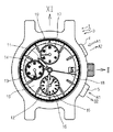
本発明による好ましい一実施例のクロノグラフ時計を備えたウオッチは、例えば、図5に示したような外観を有する。ウオッチ1は、通常の時刻表示を与える通常のアナログ式腕時計2として機能すると共にストップウオッチとしての経時表示すなわちクロノグラフ表示を与えるクロノグラフ時計3として機能する。すなわち、ウオッチ1は、通常運針の際に時刻表示を与える時針11、分針12及び秒針13並びに対応する文字板部10、14と、クロノグラフ時計動作の際にクロノグラフ時刻表示を与えるクロノグラフ時針ないし時クロノグラフ針(以下では「時クロノグラフ針」という)16、クロノグラフ分針ないし分クロノグラフ針(以下では「分クロノグラフ針」という)17及びクロノグラフ秒針ないし秒クロノグラフ針(以下では「秒クロノグラフ針」という)18並びに関連する文字板部15、19及び14とを有する。即ち、この例では、通常運針の際における時針11及び分針12による時刻表示は、大きい文字板部10で行われ、秒針13による時刻表示は、小さい文字板部14で行われる。一方、クロノグラフ動作すなわちストップウオッチ動作の際における時クロノグラフ針16及び分クロノグラフ針17による時刻表示は、夫々、対応する小さい文字板部15、19で行われ、秒クロノグラフ針18による時刻表示は、大きい文字板部10で行われる。なお、この例では、クロノグラフ分計は30分計になっている。図5において、「III」及び「XII」は、夫々、文字板10についての3時及び12時方向を指す。
【0019】
クロノグラフ時計3は、更に、スタート・ストップボタン4及びリセットボタン5を有する。ウオッチ1のクロノグラフ時計3では、通常の運針動作をしている場合、時クロノグラフ針16、分クロノグラフ針17及び秒クロノグラフ針18は、通常は、夫々、初期位置にある。クロノグラフ時計3において、スタート・ストップボタン4を、A1方向に押すと、時クロノグラフ針16、分クロノグラフ針17及び秒クロノグラフ針18が、クロノグラフ経時ないし計時動作を開始する。なお、ボタン4は、押圧後、後述のばね55によりA2方向の突出位置に戻される。クロノグラフ時計3において、スタート・ストップボタン4を再度A1方向に押すと、クロノグラフ経時ないし計時動作が停止され、時クロノグラフ針16、分クロノグラフ針17及び秒クロノグラフ針18が停止する。次に、リセットボタン5をB1方向に押すと、時クロノグラフ針16、分クロノグラフ針17及び秒クロノグラフ針18は、リセットすなわち帰零されて夫々の初期位置すなわちゼロ位置に戻る。なお、リセットボタン5は、押圧後、後述のばね86によりB2方向の突出位置に戻される。
【0020】
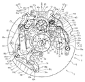
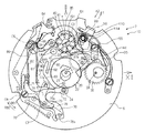
通常の計時用のアナログ式腕時計2自体は周知であるので、以下では、以上のようなウオッチ1のクロノグラフ時計3についてしかもそのうち、主として、分クロノグラフ針17及び秒クロノグラフ針18の部分について、そのクロノグラフ機構7に関して、図1から図4に基づいて説明する。図1において、「III」及び「XII」は、夫々、図5の文字板10や関連する外枠ないしケースについての3時及び12時方向を指す。
【0021】
図1において、秒クロノグラフ車20は、秒クロノグラフ真21と該真21に固定された秒クロノグラフ歯車22及び秒ハートカム23とを有し、秒クロノグラフ真21の中心軸線C1の周りで回転可能である。この秒クロノグラフ真21には、秒クロノグラフ針18が取付けられている。
【0022】
この秒クロノグラフ車20(より詳しくは秒クロノグラフ歯車22、以下同)には、秒クロノグラフ中間車24(より詳しくはその歯車、以下同)が、噛合可能である。この秒クロノグラフ中間車24は、アナログ式腕時計2の通常の時刻を表示する秒針13(図3)の秒車(図示せず)に常時噛合し、通常運針に伴い常時回転している。
【0023】
分クロノグラフ車30は、分クロノグラフ真31と該真31に固定された分クロノグラフ歯車32及び分ハートカム33とを有し、分クロノグラフ真31の中心軸線C2の周りで回転可能である。分クロノグラフ車30には、分クロノグラフ中間車34(より詳しくは、その歯車)が常時噛合している。この分クロノグラフ真31には、分クロノグラフ針17が取付けられている。分クロノグラフ歯車32には、分クロノグラフジャンパ35が規正部35aで弾性的に押付けられて、分クロノグラフ車30の回転を規正している。
【0024】
クロノグラフ機構7は、クロノグラフ動作の開始(スタート)、停止(ストップ)及びクロノグラフ針の帰零(リセット)動作を支える作動カムないしピラーホイール40を有する。作動カム40は、その中心軸線C3のまわりで回転可能であり、周面に偶数個のラチェエット歯41を備え、端面に該端面から突出した駆動歯ないしピラー42をラチェット歯41の一つおきに備える。ラチェット歯41には、地板6に基端で固定された作動カムジャンパ44の先端の規正突起45が弾性的に押付けられている。なお、この実施例では、クロノグラフ機構7がピラー(作動カム)40を有するタイプについて説明するけれども、クロノグラフ機構7は、ピラー式の代わりにカム式等他のタイプでもよい。
【0025】
作動カム40のラチェット歯41には、スタート・ストップボタン4(図2又は図5)と一体的な作動レバー50が、作動爪部51で係合可能である。作動レバー50は、スタート・ストップボタン4に当接可能なボタン作動受部52と、作動レバー支持ピン99に対してA1、A2方向に相対動可能に遊嵌された長孔53と、ばね受け54とを有する。ばね受け54には、基端55aで地板に固定された作動レバーばね55の先端55bが係止されている。従って、作動レバー50は、A1、A2方向に可動であり、作動レバーばね55によって常時A2方向の偏倚力を受けている。作動レバー50がA1方向に押圧されると、作動レバー50の作動爪部51が作動カム40のラチェット歯41に係合してA1方向に押し、作動カム40をジャンパ44の規正下で1ピッチ分だけR31方向に回転させる。作動レバー50は、A1方向の押圧後、ばね55によりA2方向に戻される。
【0026】
中心軸線C4のまわりで回動可能な停止レバー60は、一方のアーム部61の先端側縁に作動カム40の駆動歯ないしピラー42に係合可能な規正突起62を有し、他方のアーム部63の外側縁に発停レバーばね当接縁部64を有する。アーム部63は、更に、その先端部65に発停レバー当接部66を有し、先端部65の近傍に時発停伝えレバー作動ピン77aに係合する凹部67を有する。アーム部63の内側縁側には秒クロノグラフ車20の秒クロノグラフ歯車22の周面に押付けられ得る規正部68が分岐・延設されている。停止レバー60は、作動カム40がラチェット歯41の一ピッチ分回転するごとに、規正突起62が隣接駆動歯42、42の間に嵌り込んで係合する停止位置(図1や図2等)と駆動歯42の外周面に当接する停止解除位置(図6等)とを、交互に採る。停止位置では、停止レバー60はR41方向に回動して、規正部68が秒クロノグラフ車20に押付けられる。停止解除位置では、停止レバー60は、R42方向に回動して、規正部68が秒クロノグラフ車20から離れその回転を許容する。
【0027】
中心軸線C5のまわりで回動可能な発停レバーばね80は、二股に分かれたレバーばね部、すなわち停止レバーばね部81及び発停レバーばね部82を有し、停止レバーばね部81で停止レバー60の当接部64に弾性的に押付けられて停止レバー60にR41方向の回転偏倚力を及ぼし、発停レバーばね部82で発停レバー70のアーム部71に弾性的に押付けられる。
【0028】
中心軸線C6のまわりでR61、R62方向に回転可能な発停レバー70は、アーム部71に加えて、二股のアーム部分72、73を含むアーム部74を有する。アーム部分72は、先端近傍の側縁に被係合凸部75a及び当接解除凹部75bを有し、先端部で秒クロノグラフ中間車24を回転可能に支持している。
【0029】
発停レバー70のアーム部分73には、発停伝えレバー76が中心軸線C7のまわりで回動可能に連結され、発停伝えレバー76のアーム部77には前述の発停伝えレバー作動ピン77aが取付けられて、停止レバー60の係合凹部67に係合している。発停伝えレバー76のもう一方のアーム部78には、時発停レバー作動ピン78aが取付けられている。
【0030】
復針伝達レバー84は、中心軸線C5のまわりでR53、R54方向に回動可能で、作動受部84aにおいて、リセットボタン5(図5)に当接可能で、係合突起部84bで復針規正レバー85の被係合凹部85aに係合している。復針規正レバー85は回動軸85bの中心軸線C8のまわりでR81、R82方向に回動可能で、回動軸85bと復針伝達レバー84の内縁係止部84cとの間には、復針伝達レバー84にR54方向の回転偏倚力を及ぼす復針伝達レバーばね86が設けられている。ほぼU字状の復針伝達レバーばね86は、Uの湾曲底部が復針伝達レバー84のアーム部84dの内縁部84eに抱かれている。復針規正レバー85は、作動カム40の駆動歯42の列の外周にほぼ沿って延び得る形状の円弧状のアーム部87を有し、アーム部87は、隣接駆動歯42、42の間に係合可能な規正突起部87aを内周縁に備えると共に復針レバー90に係合可能な復針レバー規正突起部87bを先端部に備える。
【0031】
従って、後で詳述するようにクロノグラフ機構7がストップ状態にある際、リセットボタン5のB1方向の押圧により復針伝達レバー84がばね86のばね力に抗してR53方向に回動され係合突起部84bで被係合凹部85aをR81方向に押すと、後述のように復針規正レバー85の復針レバー規制突起部87bが復針レバー90から外れて復針レバー90によるリセット動作を許容すると共に復針規正レバー85の規正突起部87aが作動カム40の隣接駆動歯42、42の間に嵌り込む。一方、後で詳述するようにクロノグラフ機構7がリセット状態にある際に、作動カム40がラチェット歯41の一ピッチ分だけ回転されると、復針規正レバー85の規正突起部87aが駆動歯41の外周面によってR82方向に回動され、アーム部87のR82方向の回動に伴って復針レバー規制突起部87bが復針レバー90を非作動位置に戻す。
【0032】
なお、89a、89bは、夫々、時クロノグラフ針16に係る時復針伝達レバー及び時発停レバーであり、中心軸線C91のまわりで回動可能な時復針伝達レバー89aは、分クロノグラフ針17及び秒クロノグラフ針18に係る復針伝達レバー84と同様に、リセットボタン5の押圧に従って時クロノグラフ針16のリセット動作を開始させ、時復針伝達レバー89aの作動突起部89cに被係合凹部89dで係合され中心軸線C92のまわりで回動可能な時発停レバー89bはピン89eによってばね部89fで図1等において時計回りに回転偏倚され、一対の係合突起89g、89h間の凹部89jにある時発停レバー作動ピン78aと係合突起89g又は89hで係合可能である。この時クロノグラフ針16のリセット機構等は、例えば、特開平11−183653号公報に記載の機構と同様であり、ここでは、詳細な説明は省く。
【0033】
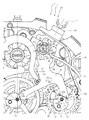
図1から図3の(a)に示したように、復針レバー90は、基端側の軸受部91で軸構造体100に回動可能に装着された基部側アーム部92と、該基部側アーム部92の先端から二股に分かれた分クロノグラフ針リセットアーム部93及び秒クロノグラフ針リセットアーム部94とを有し、ばね受部95で復針レバーばね96によってF方向の回動偏倚力を常時受けている。分クロノグラフ針リセットアーム部93は分ハートカム33の一対の最小径規定部分33aに当接可能なリセット面93aを先端に有し、秒クロノグラフ針リセットアーム部94は秒ハートカム23の一対の最小径規定部分23aに当接可能なリセット面94aを先端に有する。復針レバー90は、更に、復針規正レバー85の復針レバー規正突起部87bが係合可能な被係合段部97(係合解除可能な肩部97a)を、基部側アーム部92の内側縁に備える。
【0034】
軸構造体100は、図3の(a)に示したように、復針レバー支持手段としての作動レバー支持ピン99に加えて、固定ねじ98で固定された偏心ブシュ110を有する。作動レバー支持ピン99は、地板に装着された基端部99a及び作動レバー50の長孔部53が遊嵌された大径軸部99bに加えて、先端側の小径軸部99cを備え、該小径軸部99cに偏心ブシュ110が嵌合されている。軸部99a、99bは同一径でもよい。偏心ブシュ110は、中心軸線がCの内周側円筒面111に対して偏心した中心軸線がQの外周側円筒面112を備えた偏心筒状部113と、該筒状部113の先端から径方向外方に延在した鍔ないしフランジ状部114とを有し、フランジ状部114の表面には、内周側円筒面111の中心軸線Cに関してほぼ直径方向に延びる被係合溝115が形成されている。なお、復針レバー90の軸受部91は、偏心ブシュ110の偏心筒状部113の外周面に嵌装されている。
【0035】
従って、偏心ブシュ110の被係合溝115に小さなマイナスドライバの先端などを係合させて、ピン99の中心軸線Cのまわりで偏心ブシュ110を回動させることにより、偏心ブシュ110の偏心の向きを調整し得、この偏心の向きの調整により、復針レバー90の中心軸線すなわち調整中心軸線Qの位置を調整し得る。なお、基本中心軸線Cと偏心ないし調整中心軸線Qとの間隔は、この例では、0.05mm程度である。但し、この間隔は、復針レバー90のアーム部93、94の形状や長さ等に依存するもので、より大きくてもより小さくてもよい。
【0036】
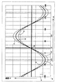
より詳しくは、図2に示した例では、偏心ブシュ110の中心軸線Qすなわち偏心ブシュ110の偏心筒状部113の外周面112の中心軸線に一致する偏心中心軸線Qの偏心方向に沿って溝115が延在しており、溝115が図2において想像線115aで示した中間位置にある場合、偏心ブシュ110が中心軸線CのまわりでR1方向に回転されると、(秒クロノグラフ針リセットアーム部94の秒ハートカムリセット面94aが秒ハートカム23の対応する部位23a、23aにより規定される面に当接するという条件下で)復針レバー90の分クロノグラフ針リセットアーム部93の先端面93aと分ハートカム30の最小径規定部分33a、33aとの隙間Gが拡がり、R2方向に回転されるとこの隙間Gが狭くなる。この位置が、図4では、点P0で示した位置に対応する。間隙Gの大きさが最小になるのは、図2の実線で示したように、秒ハートカム23の回転中心軸線C1と分ハートカム33の回転中心軸線C2とを結ぶ仮想線L1と平行で中心軸線Cを通る仮想線L2を基準として、偏心中心軸線Qが基本中心軸線Cに対して角度α=+α0(但し、時計回りの方向を+とする)だけずれた向きにある場合である(この角度αはこの例では+52度である)。
【0037】
図2の想像線で示した位置すなわち図4のグラフの点P0に対応する位置から、偏心ブシュ110がR1方向に回転されると、図4の正弦曲線S0の正方向に隙間Gが増大し、偏心ブシュ110がR2方向に回転されると、図4の正弦曲線S0の負方向に隙間Gが減少することになる。なお、図4において、正弦曲線S1は最大公差の偏心の場合を示し、正弦曲線S2は最小公差の偏心の場合を示す。
【0038】
例えば、隙間Gが「0」になるのが、図4においてG0で表した線であるようなサイズ、形状及び配置で関連部材が構成されている場合、G0はプラスマイナス0.5分未満になるように、作られ、典型的には、実線で表す位置またはその近傍になるように偏心ブシュ110が回されることになる。但し、その場合、隙間Gの大きさが公差の大小にかかわらず、すなわち線S2の場合でも、α=+α0の位置で、隙間Gの大きさがプラスマイナス0.5分相当未満である必要がある。
【0039】
従って、設計上の安全のために、例えば、隙間Gが「0」になるのが図4においてG1で表した線であるようなサイズ、形状及び配置で関連部材が構成される場合、偏心ブシュ110は、位置P0と実線位置との間で且つ復針レバー90の分クロノグラフ針リセットアーム部93の先端面93aが分ハートカム30に押付けられることのない適切な位置(間隙Gが十分に小さくなる(例えば30μm程度以下になる)位置)を採るように偏心ブシュ110が回転されることになる。
【0040】
分ハートカムリセット面93aと分ハートカム33の対応する部位33a、33aとの間に残るわずかの間隙の故に分ハートカム33に中心軸線C2のまわりでR21、R22方向に遊びが残っていても、分クロノグラフ歯車22の歯に係合する分ジャンパ35の規正部35aにより分クロノグラフ車20の回動位置は、分単位で、正確に位置決めされ得るから、隙間Gは、偏心ブシュ110によりプラスマイナス0.5分未満に低減されればよい。
【0041】
なお、偏心ブシュ110を固定ねじ98で固定する代わりに、図3の(b)に示したように、偏心ブシュ110を支持ピン99の小径円柱状部99cに単に嵌合させるようにしてもよい。
【0042】
また、偏心ブシュ110を支持ピン99と別体で形成する代わりに、偏心ブシュ110を支持ピン99と一体に形成してもよい。その場合、例えば、図3の(c)に示したように、支持ピン99hの先端部を偏心ブシュ110の偏心筒状部113の外周面112と同様に偏心した周面122を備えた円柱状部99fとして、該円柱状部99fを偏心手段として機能させてもよい。その場合、円柱状部99fの端面126に溝125を形成して、ピン99h自体を地板6などに対して中心軸線Cのまわりで回転可能にしておく。
【0043】
なお、以上においては、スタート・ストップ用の作動レバー50の支持ピン99のうち先端部側の部分をそのまま復針レバー90の偏心ブシュ110の回転中心Cを与えるピンとして併用した例について説明したけれども、これら二つのピンは、同軸に配置されなくてもよく、別々でもよい。
【0044】
次に、以上の如く構成されたウオッチ1のクロノグラフ時計3のクロノグラフ機構7について、リセット位置の調整操作及びリセット動作を中心としたクロノグラフ動作に関して、説明する。
【0045】
ウオッチ1の通常の運針動作においては、クロノグラフ機構7は、図1に示したようなリセット状態を採る。従って、クロノグラフ機構7のリセット位置の調整は、ウオッチ1の全体がまだ組立てられていない点を除いてこの通常運針状態と同様な状態おいて、行われる。
【0046】
クロノグラフ機構7のリセット位置の調整は、固定ねじ98(図3の(a))の取付前で且つ秒クロノグラフ針18の取付前に行われる。また、マイナスドライバの先端部を偏心ブシュ110のフランジ状部114の係合溝115に係合させて偏心ブシュ110を中心軸線Cのまわりで回転させることによって、偏心ブシュ110を、例えば、図2の想像線で示した初期位置(図4において点P0で示す位置)に設定しておく。次に、復針レバーばね96の作用下において復針レバー90を偏心ブシュ110のまわりで即ち偏心ブシュ110の外周面112の中心軸線Qのまわりで回して、秒クロノグラフ針リセットアーム部94を秒ハートカム23に当てる。秒クロノグラフ針リセットアーム部94の先端面94aが秒ハートカム23の二つの対称な最近接位置23a、23aの両方に当るように、秒クロノグラフ針リセットアーム部94の先端面94aに対して秒ハートカム23の向き即ち秒クロノグラフ車20の中心軸線C1のまわりでの回転方向を調整する。次に、この状態において、分クロノグラフ車30を復針レバー90の分クロノグラフ針リセットアーム部93の先端面93aに対して、可能な限り位置合せする。
【0047】
このとき、分クロノグラフ車30の分ハートカム33が分クロノグラフ針リセットアーム部93の先端面93aによって規制される可動範囲が、プラスマイナス0.5分未満の範囲であれば、その位置は、分ハートカム33に対しても復針レバー90が一応適正に位置決めされていることになる。更に、所望ならば、先端面93aと分ハートカム33との隙間Gの大きさを目視等で判定してもよい。
【0048】
一方、分クロノグラフ針リセットアーム部93の先端面93aによって規制される分ハートカム33の可動範囲がプラスマイナス0.5分を越える場合、分クロノグラフ針リセットアーム部93の先端面93aと分ハートカム33の最近接部33a、33aとの間の隙間ないし間隙Gの大きさが大き過ぎる(この大きさは目視で判定してもよい)ので、偏心ブシュ110を支持ピン99に対してR1方向に回すことにより、この間隙を小さくする。なお、偏心ブシュ110の回転は、復針レバー90の秒クロノグラフ針リセットアーム部94の先端面94aの向きや位置を多少なりとも変化させることになるので、偏心ブシュ110を所望角度回転させる毎に秒クロノグラフ針リセットアーム部94の先端面94aが秒ハートカム23の二つの対称な最近接位置23a、23aの両方に当るように、復針レバー90及び秒ハートカム23の位置を調整する。いずれにしても、この間隙サイズ低減ないし減少操作によって、分クロノグラフ針リセットアーム部93の先端面93aにより規制される分ハートカム33の可動範囲が、プラスマイナス0.5分未満になると、隙間Gは適正な範囲内に抑えこまれたことになる。なお、この状態においてなお分ハートカム33の可動範囲が比較的広く且つ隙間の適度な低減が更に可能であれば、偏心ブシュ110を更にQ1方向に回して、分ハートカム33の可動範囲をより小さくしてもよい。
【0049】
このようにして、秒ハートカム23を含む秒クロノグラフ車20(但し、この段階では、秒クロノグラフ針は含まれない)及び復針レバー90が所定位置に位置決めされ、分ハートカム33を含む分クロノグラフ車30が所定範囲内に位置に位置決めされる。なお、分クロノグラフ歯車32には、分クロノグラフジャンパ35が係合しているので、分クロノグラフ針リセットアーム部93の先端面93aによって分ハートカム33すなわち分クロノグラフ車30が、例えばプラス・マイナス0.5分未満の精度で位置決めされれば、それ未満のズレは、分クロノグラフジャンパ35によって強制的に規正され得る。
【0050】
このような位置決めが完了すると、固定ねじ98が締められて、偏心ブシュ110が支持ピン98に対して、固定される。更に、最後に、秒クロノグラフ針18が、文字板10上で適正なゼロ位置をとるように、秒クロノグラフ真21に取り付けられて、リセット位置における位置決め乃至調整すなわち隙間Gの管理が完了する。
【0051】
この位置調整に際して、実際上単に偏心ブシュ110を軸線Cのまわりで実際上、プラス・マイナス90度未満の範囲内で回転させればよいので、その位置調整が容易且つ確実に行われ得る。また、偏心ブシュ110の回転には、該偏心ブシュ110と係合するもの(この例では溝114に係合するマイナスドライバなど)をブシュ110に係合させて回せばよいので、従来の非円柱状ピンの打込みや強制回転と比較して、隙間Gの調整ないし管理が容易に行われ得る。
【0052】
また、この場合、復針レバー90の回転中心に偏心ブシュ110を介在させるだけでよいから、非円柱状ピンを打込む場合のようにピン打込み用の孔やピンの向きに応じて異なる程度に割れるべき割溝等を復針レバーに設ける必要がないので、過大なスペースを要しないだけでなく復針レバーの構造が簡単化され得、その寸法・形状の精度も高められ得る。
【0053】
クロノグラフ機構7のクロノグラフ動作自体は、従来のクロノグラフ機構と同様である。
【0054】
すなわち、図1に示した通常運針状態(クロノグラフ機構7のリセット状態)において、図5のスタート・ストップボタン4をA1方向に押すと、作動レバー50がA1方向に押しこまれ、爪51によって作動カム(ピラーホイール)40がラチェット歯41の一ピッチ分だけ回転される。このとき、復針規正レバー85の規正部87aが隣接駆動歯(ピラー)42、42間の凹部から外れ駆動歯42の外周面に押し上げられてR82方向に回転し先端部87bが復針レバー90の肩部97aに係合して復針レバー90をRQ2方向に回転させて復針レバー90のアーム部94、93の分及び秒ハートカム33、23に対する干渉を完全に解除すると共に、復針レバー90の係合部97に係合する。また、作動カム40の回転に伴い、停止レバー60の規正部62が隣接駆動歯42、42間の凹部から駆動歯42の外周面に押し上げられて停止レバー60がR42方向に回転し、それにより発停レバーばね80を介して発停レバー70がR61方向に回転されて、秒クロノグラフ中間車24が秒クロノグラフ歯車22に噛合する。その結果、秒クロノグラフ中間車24を介して秒クロノグラフ車20の回転が開始され、クロノグラフ動作が開始される(図6)。
【0055】
一方、スタート・ストップボタン4(図5)を再度A1方向に押すと、作動レバー50を介して作動カム40がラチェット歯41の一ピッチ分だけ再度回転される。その結果、停止レバー60の規正部62が作動カム40の隣接駆動歯42、42間の凹部に再度嵌り込んで、R41方向に回転され、それにより発停レバーばね80を介して発停レバー70がR62方向に回転されて、秒クロノグラフ中間車24の秒クロノグラフ歯車22に対する噛合が解除される。また、停止レバー60のR41方向回転により、停止レバー60のばね部68が秒クロノグラフ歯車22に周面に当接して秒クロノグラフ車20を停止位置に保つ。これにより、クロノグラフ機構7は、停止状態を採る(図7)。
【0056】
クロノグラフ機構7をリセットして通常運針状態に戻すには、リセットボタン5(図5)をB1方向に押して、図7の復針伝達レバー84をB1方向に押下げる。これにより、係合構造84b、85aを介して復針規正レバー85がR81方向に回転され、復針規正レバー85の先端突起部87bが復針レバー90をRQ1方向に押して該復針レバー90の肩部97aから外れ、復針規正レバー85の規正部87bが作動カム40の隣接駆動歯42、42間の凹部に嵌る。復針規正レバー85が復針レバー90から外れると、復針レバー90は、復針レバーばね96の作用下でRQ2方向に回転され、秒クロノグラフ針リセットアーム部94の先端面94aが秒ハートカム23にぶつかって、秒ハートカム23を初期位置に位置決めすることにより、秒クロノグラフ車20を初期位置に戻し、秒クロノグラフ針18をリセットする。偏心ブシュ110により位置調整された復針レバー90のRQ2方向の回転に伴い、同時に、分クロノグラフ針リセットアーム部93の先端面93aが分ハートカム33にぶつかって、分ハートカム33を初期位置の近傍に戻し、分クロノグラフジャンパ35の作用下で、分クロノグラフ車30が正確に初期位置に戻され、分クロノグラフ針17がリセットされる。
【0057】
なお、以上においては、時クロノグラフ針については、説明しなかったけれども、時クロノグラフ針は例えば特開平11−183653号公報に記載されているような従来の機構と同様の機構により、クロノグラフ動作せしめられる。
【図面の簡単な説明】
【図1】本発明による好ましい一実施例の時計のクロノグラフ機構について非作動状態(またはリセット状態)すなわち通常運針状態を示した平面説明図(XII及びIIIは、夫々、12時方向及び3時方向を示す)。
【図2】図1のクロノグラフ機構の復針レバー及びその偏心位置調整のための関連部品についての拡大平面説明図(但し、固定ねじの取付前の状態)。
【図3】図2のクロノグラフ機構の偏心支持部分の断面(図2のほぼIIIA−IIIA線断面)を拡大して示したもので、(a)は断面説明図、(b)及び(c)は夫々変形例についての同様な断面説明図。
【図4】図2のクロノグラフ機構の偏心ブシュの回動位置と分ハートカム及び復針レバーの面の間の隙間の大きさとの関係を模式的に示したグラフ。
【図5】図1のクロノグラフ機構を備えた時計の一例の正面説明図。
【図6】図1のクロノグラフ機構について、クロノグラフ動作のスタート状態を示した平面説明図。
【図7】図1のクロノグラフ機構について、クロノグラフ動作のストップ状態を示した平面説明図。
【符号の説明】
1 ウオッチ
2 アナログ式腕時計
3 クロノグラフ時計
4 スタート・ストップボタン
5 リセットボタン
7 クロノグラフ機構
11、12、13 針(通常運針ないし通常計時用)
16 時クロノグラフ針(クロノグラフ時針)
17 分クロノグラフ針(クロノグラフ分針)
18 秒クロノグラフ針(クロノグラフ秒針)
20 秒クロノグラフ車
21 秒クロノグラフ真
22 秒クロノグラフ歯車
23 秒ハートカム
23a、33a 最小径規定部
24 秒クロノグラフ中間車
30 分クロノグラフ車
31 分クロノグラフ真
32 分クロノグラフ歯車
33 分ハートカム
35 分クロノグラフジャンパ
40 作動カム(ピラーホイール)
41 ラチェット歯
42 駆動歯(ピラー)
44 作動カムジャンパ
50 作動レバー(クロノグラフ動作スタート・ストップ)
60 停止レバー
70 発停レバー
76 発停伝えレバー
80 発停レバーばね
84 復針伝達レバー
85 復針規正レバー
87b 復針レバー規制突起部
90 復針レバー
91 軸受部
92 基部側アーム部
93 分クロノグラフ針リセットアーム部
93a、94a 先端当接面
94 秒クロノグラフ針リセットアーム部
98 固定ねじ
99 ピン
99f 偏心軸部(偏心手段)
110 偏心ブシュ(偏心手段)
113 偏心筒状部
114 フランジ状部
115 被係合溝
122 偏心周面
C 中心軸線(基本中心軸線)
G 隙間
Q 偏心中心軸線(調整中心軸線)
R1、R2 中心軸線Cのまわりでの回動方向
QR1、QR2 偏心中心軸線Qのまわりでの回動方向[0001]
BACKGROUND OF THE INVENTION
The present invention relates to a mechanical chronograph timepiece.
[0002]
[Prior art]
By using a hammer that has a base side arm part and a minute chronograph hand reset arm part and a second chronograph hand reset arm part that are bifurcated at the tip of the base side arm part, the minute chronograph hand and the second chronograph It is known to return (reset) the graph hand to the initial position. In this type of hammer, the proximal end of the base arm of the lever is pivotally supported by a pivot shaft, and the minute chronograph hand reset arm and second by the pivot biasing force of the hammer lever spring. The minute chronograph and second chronograph hands are reset by hitting the respective tip of the chronograph hand reset arm to the corresponding heart cam, that is, the minute heart cam and the second heart cam and returning the respective heart cams to their initial positions. It is configured.
[0003]
In this type of mechanical chronograph watch, in consideration of various manufacturing tolerances, with the tip of the second chronograph hand reset arm in contact with the second heart cam, the tip of the minute chronograph hand reset arm It is also known that the size of the gap can be adjusted so that the gap with the minute heart cam becomes sufficiently small. In order to adjust the gap, in a conventional mechanical chronograph timepiece, a circular hole is formed at the root of the bifurcated portion of the hammer, that is, the distal end of the base side arm portion, and the hole and the bifurcated portion are formed on the peripheral wall of the hole. Insert a notch that connects the two and insert a non-cylindrical pin with an oval cross-section into the circular hole, and then rotate and turn the non-cylindrical pin within the circular hole to change and adjust the opening of the notch. Thus, the manner or degree of deformation of the hammer is adjusted, that is, the relative position of the tip of the minute chronograph hand reset arm with respect to the tip of the second chronograph hand reset arm is changed and adjusted.
[0004]
[Problems to be solved by the invention]
However, the hammer has the rigidity necessary to mechanically return each heart cam to the initial position when each chronograph needle reset arm portion hits the corresponding heart cam under the action of the hammer lever spring. Because it is made of a material with relatively high rigidity such as iron, it is not always easy to drive a non-cylindrical pin, and the non-cylindrical pin rotates in a predetermined direction against the rigidity of the hammer. It is not easy to make it. In addition, it is not only necessary to provide a split groove that connects to the back hole in the bifurcated part of the hammer, but it is also necessary to provide an eccentric pin separately, which not only complicates the structure of the part but also provides a space for driving the pin It is also necessary to secure a space that allows free rotation of the bifurcated portion into which the pin is driven.
[0005]
The present invention has been made in view of the above points, and an object thereof is to provide a mechanical chronograph timepiece in which the hammer position can be easily adjusted.
[0006]
[Means for Solving the Problems]
In order to achieve the above object, the mechanical chronograph timepiece of the present invention has a hammer operating means for defining a basic center axis, and is attached to the hammer operating means and is eccentric with respect to the basic central axis of the supporting means. Eccentric means for defining the adjustment center axis, which can adjust the direction of the eccentricity of the adjustment center axis with respect to the basic center axis, and supported by the eccentric means so as to be rotatable around the adjustment center axis at the base end portion. Reversing lever provided with two types of chronograph needle reset arm parts branched and extended from the tip part of the base side arm part and the base side arm part, and a chronograph needle reset arm part to which each corresponds Heart cams that are capable of returning to their initial positions when pressed by their distal ends, each attached to a corresponding type of chronograph needle.
[0007]
In the mechanical chronograph timepiece of the present invention, “an eccentric means that is attached to the hammer operating means and defines an adjustment center axis that is eccentric with respect to the basic center axis of the support means, the basic center axis of the adjustment center axis. Since the eccentric direction can be adjusted by operating this adjustable eccentric means, the two chronograph needle reset arm parts of the hammer can be adjusted. The initial position can be adjusted, thereby adjusting the initial positions of the two types of heart cams defined according to the initial positions of the two types of chronograph hand reset arm portions. Therefore, it is only necessary to adjust the position of the hammer by adjusting the eccentric direction of the eccentric means after attaching the hammer to the hammer supporting means at an approximate position via the eccentric means. No special skill or experience is required for mounting the hammer, it is possible to perform quick assembly at low cost, and accurate positioning of the hammer can be performed easily.
[0008]
The two types of chronograph hands are typically any two of “hour chronograph hands”, “minute chronograph hands” and “second chronograph hands”. When the exact position of one of the two chronograph hands can be defined by a jumper that engages a gear tooth integral with the chronograph needle, the heart cam integral with the other chronograph needle When the corresponding reset arm portion of the hammer is positioned, the clearance between the heart cam integral with the one chronograph needle and the corresponding reset arm portion of the hammer is a unit rotation angle of the gear. What is necessary is just to adjust with an eccentric means so that it may become less. The two types of chronograph hands are typically a second chronograph hand and a minute chronograph hand. However, other combinations may be used if desired. When adjusting the reset position of the second and minute chronograph hands, especially for the second chronograph hands where the deviation of the reset position is conspicuous, the initial state is that the corresponding reset arm part of the hammer and the second heart cam are in contact. In the initial position, the second chronograph hand is attached to the second chronograph that is integrated with the second heart cam in accordance with the direction of the corresponding dial, and the reset position of the minute chronograph hand is adjusted by the clearance by eccentric means. Do. However, in the case where a jumper is associated with the second chronograph gear, the reset position of the second heart cam related to the second chronograph hand may be determined by adjusting the gap by the eccentric means, if desired.
[0009]
In the mechanical chronograph timepiece of the present invention, typically, the eccentric means is fitted to the hammer lever support means so as to be rotatable around the basic central axis, and the base side arm portion of the hammer is the adjustment central axis. And is fitted to an eccentric means so as to be rotatable around. The hammer lever support means for defining the basic center axis may be a shaft or a bearing or hole defining means for receiving the shaft. Similarly, the eccentric means for defining the adjustment center axis may be a shaft or bearing or hole defining means for receiving the shaft. It may be a means.
[0010]
Here, the diameter of the portion of the eccentric means fitted to the hammer lever support means is typically smaller than the diameter of the portion of the eccentric means fitted to the base arm portion of the hammer. . However, it can be the same or larger if desired.
[0011]
In this case, in the mechanical chronograph timepiece of the present invention, for example, the hammer operating means is supported by the base plate and has a cylindrical central axis centered on the basic central axis, and the eccentric means is a cylindrical inner peripheral surface. A ground plane in which the hammer operating means is provided with a cylindrical hole centered on the basic central axis even if it has an eccentric bush with an outer peripheral surface fitted to the central shaft and eccentric with respect to the inner peripheral surface A lever-side cylindrical shape that is formed on one end side of the base-side cylindrical portion and eccentric with respect to the base-side cylindrical portion. May have a part.
[0012]
In the mechanical chronograph timepiece of the present invention, typically, an engaged portion extending substantially in the diametrical direction with respect to the reference central axis is formed on the surface of the eccentric means so that the direction of the eccentricity by the eccentric means can be adjusted. Is done.
[0013]
In that case, the direction of the eccentricity can be adjusted easily and accurately by engaging and rotating the engaging portion such as the tip of the tool with the engaged portion. Here, the engaged portion includes, for example, a groove extending in the diameter direction. However, the engaged portion may be formed on the peripheral surface instead of the end surface of the eccentric means. In that case, the engaged portion is formed of, for example, a roughened peripheral surface region.
[0014]
In the chronograph timepiece of the invention, typically, for example, the hammer operating means is supported by the main plate and has a cylindrical center axis centered on the basic center axis, and the eccentric means is a cylindrical inner peripheral surface. An eccentric bushing having an outer peripheral surface that is fitted to the central shaft and is eccentric with respect to the inner peripheral surface is provided. In that case, the direction of the eccentricity can be adjusted only by rotating the eccentric bushing with respect to the central axis. In that case, typically, the eccentric bush has a flange-like portion, and an engaged groove extending substantially diametrically with respect to the reference central axis is formed on the surface of the flange-like portion. In this case, the eccentric bushing can be easily rotated, and the eccentric bushing itself may be rotated with respect to the central axis in accordance with the rotation of the hammer, etc., despite the easy adjustment of the eccentric direction. There are few. However, after positioning the eccentric bushing with respect to the central axis, it is preferable to fix the eccentric bushing to the central axis in order to avoid the possibility of the eccentric bushing being displaced from the central axis (changing the direction of eccentricity). Means are provided. As this fixing means, for example, a screw is used. However, any other fixing means may be used.
[0015]
In the mechanical chronograph timepiece of the present invention, the chronograph hands typically include a second chronograph hand and a non-second chronograph hand, and one of the hammers corresponding to the second heart cam is reset. When the tip of the arm is in contact with the second heart cam and returns the second heart cam to the initial position, the return lever returns to the tip of the other chronograph hand reset arm corresponding to the non-second heart cam. The relative position of the position with the non-second heart cam is adjusted according to the direction of the eccentricity of the eccentric means.
[0016]
The mechanical chronograph timepiece as described above is typically incorporated in a watch. In this case, the watch typically comprises a mechanical analog watch, but if desired, the hand movement control portion may be an electronic timepiece.
[0017]
DETAILED DESCRIPTION OF THE INVENTION
Several preferred embodiments of the present invention will be described based on preferred examples shown in the accompanying drawings.
[0018]
【Example】
A watch including a chronograph timepiece according to a preferred embodiment of the present invention has an appearance as shown in FIG. The
[0019]
The chronograph timepiece 3 further includes a start /
[0020]
Since the
[0021]
In FIG. 1, a
[0022]
The second chronograph wheel 20 (more specifically, the second chronograph gear wheel 22, hereinafter the same) can be meshed with a second chronograph intermediate wheel 24 (more specifically, the gear, the same hereafter). This second chronograph
[0023]
The
[0024]
The chronograph mechanism 7 has an operating cam or
[0025]
An
[0026]
The
[0027]
The start /
[0028]
The start /
[0029]
A start /
[0030]
The
[0031]
Accordingly, when the chronograph mechanism 7 is in the stopped state as will be described in detail later, the
[0032]
In addition, 89a and 89b are respectively an hour hammer transmission lever and an hour stop lever for the
[0033]
As shown in FIG. 1 to FIG. 3A, the
[0034]
As shown in FIG. 3A, the
[0035]
Accordingly, by engaging the tip of a small minus driver with the engaged
[0036]
More specifically, in the example shown in FIG. 2, the groove along the eccentric direction of the eccentric central axis Q coincides with the central axis Q of the
[0037]
When the
[0038]
For example, if the related member is configured with a size, shape, and arrangement such that the gap G is “0” in the line represented by G0 in FIG. 4, G0 is less than plus or minus 0.5 minutes. Thus, the
[0039]
Therefore, for safety in design, for example, when the related member is configured with a size, shape, and arrangement such that the gap G becomes “0” as a line represented by G1 in FIG. 110 is an appropriate position between the position P0 and the solid line position and the tip surface 93a of the minute chronograph hand
[0040]
Even if play remains in the R21 and R22 directions around the central axis C2 in the minute heart cam 33 due to the slight gap remaining between the minute heart cam reset surface 93a and the corresponding portions 33a and 33a of the minute heart cam 33, the minute chrono Since the rotation position of the
[0041]
Instead of fixing the
[0042]
Further, instead of forming the
[0043]
In the above description, an example in which the tip portion of the
[0044]
Next, regarding the chronograph mechanism 7 of the chronograph timepiece 3 of the
[0045]
In the normal hand movement operation of the
[0046]
The reset position of the chronograph mechanism 7 is adjusted before the fixing screw 98 (FIG. 3A) is attached and before the
[0047]
At this time, if the movable range in which the minute heart cam 33 of the
[0048]
On the other hand, when the movable range of the minute heart cam 33 restricted by the tip surface 93a of the minute chronograph hand
[0049]
In this way, the
[0050]
When such positioning is completed, the fixing
[0051]
In this position adjustment, the
[0052]
In this case, since the
[0053]
The chronograph operation itself of the chronograph mechanism 7 is the same as the conventional chronograph mechanism.
[0054]
That is, when the start /
[0055]
On the other hand, when the start / stop button 4 (FIG. 5) is pushed again in the A1 direction, the
[0056]
To reset the chronograph mechanism 7 to return to the normal hand movement state, the reset button 5 (FIG. 5) is pushed in the B1 direction, and the
[0057]
Although the hour chronograph hand has not been described above, the hour chronograph hand is operated by a mechanism similar to the conventional mechanism described in, for example, JP-A-11-183653. It can be operated.
[Brief description of the drawings]
FIG. 1 is an explanatory plan view showing a non-operating state (or reset state), that is, a normal hand movement state of a chronograph mechanism of a preferred embodiment of a timepiece according to the present invention (XII and III are respectively 12 o'clock direction and 3 o'clock) Show directions).
2 is an enlarged plan view of the hammer of the chronograph mechanism and related parts for adjusting the eccentric position of the chronograph mechanism of FIG. 1 (however, before the fixing screw is attached);
3 is an enlarged cross-sectional view (substantially taken along the line IIIA-IIIA in FIG. 2) of the eccentric support portion of the chronograph mechanism of FIG. 2, in which (a) is a cross-sectional explanatory view, (b) and (c); ) Is a cross-sectional explanatory view similar to each of the modified examples.
4 is a graph schematically showing the relationship between the rotational position of the eccentric bush of the chronograph mechanism of FIG. 2 and the size of the gap between the minute heart cam and the hammer.
5 is an explanatory front view of an example of a timepiece having the chronograph mechanism of FIG. 1. FIG.
6 is an explanatory plan view showing a start state of the chronograph operation with respect to the chronograph mechanism of FIG. 1. FIG.
7 is an explanatory plan view showing a stop state of the chronograph operation in the chronograph mechanism of FIG. 1; FIG.
[Explanation of symbols]
1 watch
2 Analog watches
3 Chronograph clock
4 Start / Stop button
5 Reset button
7 Chronograph mechanism
11, 12, 13 hands (normal hand movement or normal timekeeping)
16:00 chronograph hand (chronograph hour hand)
17 minute chronograph hand (chronograph minute hand)
18-second chronograph hand (chronograph second hand)
20 second chronograph car
21 seconds chronograph true
22-second chronograph gear
23 seconds heart cam
23a, 33a Minimum diameter defining part
24 second chronograph intermediate car
30 minute chronograph car
31 minute chronograph true
32 minute chronograph gear
33 minutes heart cam
35 minute chronograph jumper
40 Actuating cam (pillar wheel)
41 ratchet teeth
42 Drive teeth (pillars)
44 Actuating cam jumper
50 Actuating lever (Chronograph operation start / stop)
60 Stop lever
70 Start / stop lever
76 Start / stop notification lever
80 On / off lever spring
84 hammer transmission lever
85 hammer setting lever
87b Return lever restricting projection
90 Return lever
91 Bearing
92 Base side arm
93 minute chronograph hand reset arm
93a, 94a Tip contact surface
94 second chronograph hand reset arm
98 fixing screw
99 pins
99f Eccentric shaft (eccentric means)
110 Eccentric bush (Eccentric means)
113 Eccentric tubular part
114 Flange-shaped part
115 engaged groove
122 Eccentric circumferential surface
C Center axis (basic center axis)
G gap
Q Eccentric center axis (adjustment center axis)
R1, R2 Direction of rotation around the central axis C
QR1, QR2 Direction of rotation around the eccentric center axis Q
Claims (5)
前記復針レバー支持手段に装着され該支持手段の前記基本中心軸線に対して偏心した調整中心軸線を規定する偏心手段であって、前記調整中心軸線の前記基本中心軸線に対する偏心の向きが調整可能なものと、
基端部において前記調整中心軸線のまわりで回動可能に偏心手段に支持された基部側アーム部及び該基部側アーム部の先端部から二股に分岐・延在してなる二種類のクロノグラフ針リセットアーム部を備えた復針レバーと、
夫々が対応する前記クロノグラフ針リセットアーム部の先端部によって押圧された際に初期位置に復帰可能なハートカムであって、夫々が対応する種類のクロノグラフ針に取付けられたものとを有し、
前記偏心手段が前記基本中心軸線のまわりで回動可能に前記復針レバー支持手段に嵌合され、前記復針レバーの前記基部側アーム部が調整中心軸線のまわりで回動可能に前記偏心手段に嵌合され、
前記偏心手段による偏心の向きが調整され得るように前記偏心手段のフランジ状部の表面に基準中心軸線に関して実質的に直径方向に延びた被係合部が形成され、
前記フランジ状部の外径が、前記被係合部と係合する固定ねじの外径より大きく、
前記クロノグラフ針が、秒クロノグラフ針と分クロノグラフ針とを含み、前記復針レバーのうち秒ハートカムに対応する一方のクロノグラフ針リセットアーム部の先端部が秒ハートカムに当接して該秒ハートカムを初期位置に復帰させる状態にある際、前記偏心手段による偏心の向きが調整されることにより、前記復針レバーのうち前記分ハートカムに対応する他方のクロノグラフ針リセットアーム部の先端部により復帰位置の分ハートカムの可動範囲がプラスマイナス0.5分未満に規制されるとともに、
前記分クロノグラフ針が取付けられる分クロノグラフ真に固定される分クロノグラフ歯車の歯に係合する分クロノグラフジャンパが、弾性的に押し付けて前記分クロノグラフ歯車の回転を規正するように構成された機械式クロノグラフ時計。Hammer operating means for defining the basic central axis,
Eccentric means that is mounted on the hammer operating means and defines an adjustment center axis that is eccentric with respect to the basic center axis of the support means, and the direction of the eccentricity of the adjustment center axis with respect to the basic center axis can be adjusted. What
Two types of chronograph needles which are bifurcated and extended from the base end side arm portion supported by the eccentric means so as to be rotatable around the adjustment center axis at the base end portion, and from the tip end portion of the base side arm portion Hammer with a reset arm,
A heart cam capable of returning to the initial position when each is pressed by the tip of the corresponding chronograph needle reset arm, each attached to a corresponding type of chronograph needle,
The eccentric means is fitted to the hammer lever support means so as to be rotatable about the basic central axis, and the base side arm portion of the hammer is rotatable about the adjustment central axis. Fitted into the
An engaged portion extending substantially diametrically with respect to a reference central axis is formed on the surface of the flange-like portion of the eccentric means so that the direction of the eccentricity by the eccentric means can be adjusted,
An outer diameter of the flange-shaped portion is larger than an outer diameter of a fixing screw engaged with the engaged portion;
The chronograph hand includes a second chronograph hand and a minute chronograph hand, and the tip of one chronograph hand reset arm portion corresponding to the second heart cam of the hammer is in contact with the second heart cam and the second When the heart cam is in the state of returning to the initial position, by adjusting the direction of eccentricity by the eccentric means, the tip of the other chronograph needle reset arm portion corresponding to the minute heart cam among the hammers is adjusted. The movable range of the heart cam is restricted to less than plus or minus 0.5 minutes as much as the return position,
A minute chronograph jumper that engages the teeth of a minute chronograph gear that is fixed to the minute chronograph to which the minute chronograph hand is attached is configured to elastically press to regulate the rotation of the minute chronograph gear. Mechanical chronograph watch.
Priority Applications (7)
| Application Number | Priority Date | Filing Date | Title |
|---|---|---|---|
| JP2002202509A JP4820522B2 (en) | 2002-07-11 | 2002-07-11 | Mechanical chronograph watch |
| EP03254332A EP1380906B1 (en) | 2002-07-11 | 2003-07-08 | Mechanical chronograph timepiece |
| DE60330630T DE60330630D1 (en) | 2002-07-11 | 2003-07-08 | Mechanical chronograph watch |
| TW092118751A TW200402613A (en) | 2002-07-11 | 2003-07-09 | Mechanical chronograph timepiece |
| US10/616,389 US20040052162A1 (en) | 2002-07-11 | 2003-07-09 | Mechanical chronograph timepiece |
| CNB031495648A CN100464259C (en) | 2002-07-11 | 2003-07-11 | Mechanical timing timepiece |
| HK04107767.2A HK1065122B (en) | 2002-07-11 | 2004-10-08 | Mechanical chronograph timepiece |
Applications Claiming Priority (1)
| Application Number | Priority Date | Filing Date | Title |
|---|---|---|---|
| JP2002202509A JP4820522B2 (en) | 2002-07-11 | 2002-07-11 | Mechanical chronograph watch |
Related Child Applications (1)
| Application Number | Title | Priority Date | Filing Date |
|---|---|---|---|
| JP2009166041A Division JP4974387B2 (en) | 2009-07-14 | 2009-07-14 | Mechanical chronograph watch |
Publications (2)
| Publication Number | Publication Date |
|---|---|
| JP2004045191A JP2004045191A (en) | 2004-02-12 |
| JP4820522B2 true JP4820522B2 (en) | 2011-11-24 |
Family
ID=29728499
Family Applications (1)
| Application Number | Title | Priority Date | Filing Date |
|---|---|---|---|
| JP2002202509A Expired - Lifetime JP4820522B2 (en) | 2002-07-11 | 2002-07-11 | Mechanical chronograph watch |
Country Status (6)
| Country | Link |
|---|---|
| US (1) | US20040052162A1 (en) |
| EP (1) | EP1380906B1 (en) |
| JP (1) | JP4820522B2 (en) |
| CN (1) | CN100464259C (en) |
| DE (1) | DE60330630D1 (en) |
| TW (1) | TW200402613A (en) |
Families Citing this family (4)
| Publication number | Priority date | Publication date | Assignee | Title |
|---|---|---|---|---|
| JP5466060B2 (en) * | 2010-03-25 | 2014-04-09 | セイコーインスツル株式会社 | Switch structure, chronograph mechanism and electronic timepiece using the same |
| JP6564561B2 (en) * | 2013-05-31 | 2019-08-21 | ロレックス・ソシエテ・アノニムRolex Sa | Clock mechanism for storing and displaying time information |
| JP6567806B2 (en) * | 2013-05-31 | 2019-08-28 | ロレックス・ソシエテ・アノニムRolex Sa | Clock mechanism for storing and displaying time information |
| USD820692S1 (en) * | 2016-12-15 | 2018-06-19 | Montblanc-Simplo Gmbh | Watch |
Family Cites Families (13)
| Publication number | Priority date | Publication date | Assignee | Title |
|---|---|---|---|---|
| CH227300A (en) * | 1940-12-19 | 1943-05-31 | Jacot Guyot Henri | Chronograph. |
| CH271999A (en) * | 1948-04-21 | 1950-11-30 | Vve James Aubert & Cie | Chronograph. |
| CH285850A (en) * | 1950-07-31 | 1952-09-30 | Excelsior Park Les Fils De Jea | Timepiece. |
| JPS4938699Y1 (en) * | 1970-12-28 | 1974-10-23 | ||
| US3701250A (en) * | 1970-12-28 | 1972-10-31 | Xerox Corp | Adjustable return mechanism for a watch |
| GB1405101A (en) * | 1971-08-20 | 1975-09-03 | Smiths Industries Ltd | Reset mechanisms for use in stopwatches |
| JPS4975373A (en) * | 1972-11-24 | 1974-07-20 | ||
| CH500273A4 (en) * | 1973-04-06 | 1975-05-30 | ||
| GB1454624A (en) * | 1973-08-30 | 1976-11-03 | Suwa Seikosha Kk | Electric timepiece |
| CH678910GA3 (en) * | 1990-03-06 | 1991-11-29 | Chronograph zero resetting mechanism - provides simultaneous resetting of second and minute hands via respective cams | |
| CH690524A5 (en) * | 1995-10-31 | 2000-09-29 | Rolex Montres | Piece chronograph mechanism watchmaking. |
| JP3568763B2 (en) * | 1997-12-22 | 2004-09-22 | セイコーインスツルメンツ株式会社 | Chronograph clock with start / stop lever and chronograph receiver |
| WO2002077725A1 (en) * | 2001-03-21 | 2002-10-03 | Glashütter Uhrenbetrieb GmbH | Chronograph with two rotational directions |
-
2002
- 2002-07-11 JP JP2002202509A patent/JP4820522B2/en not_active Expired - Lifetime
-
2003
- 2003-07-08 DE DE60330630T patent/DE60330630D1/en not_active Expired - Lifetime
- 2003-07-08 EP EP03254332A patent/EP1380906B1/en not_active Expired - Lifetime
- 2003-07-09 US US10/616,389 patent/US20040052162A1/en not_active Abandoned
- 2003-07-09 TW TW092118751A patent/TW200402613A/en unknown
- 2003-07-11 CN CNB031495648A patent/CN100464259C/en not_active Expired - Lifetime
Also Published As
| Publication number | Publication date |
|---|---|
| JP2004045191A (en) | 2004-02-12 |
| EP1380906A3 (en) | 2005-06-01 |
| HK1065122A1 (en) | 2005-02-08 |
| CN1489011A (en) | 2004-04-14 |
| CN100464259C (en) | 2009-02-25 |
| EP1380906B1 (en) | 2009-12-23 |
| EP1380906A2 (en) | 2004-01-14 |
| US20040052162A1 (en) | 2004-03-18 |
| DE60330630D1 (en) | 2010-02-04 |
| TW200402613A (en) | 2004-02-16 |
Similar Documents
| Publication | Publication Date | Title |
|---|---|---|
| JP3336041B2 (en) | Operating mechanism for watch | |
| JP3256908B2 (en) | Mechanical and / or electromechanical timepiece with automatic reverse display | |
| US6761478B2 (en) | Chronograph with two rotational directions | |
| US7170824B2 (en) | Calendar mechanism having means driving and correcting two indicators | |
| JP3081992B2 (en) | Wristwatch with calendar | |
| JP3568763B2 (en) | Chronograph clock with start / stop lever and chronograph receiver | |
| WO1999032944A1 (en) | Chronograph timepiece | |
| JP3081991B2 (en) | Self-winding wristwatch | |
| US8545092B2 (en) | Timepiece comprising a chronograph mechanism | |
| JP6492928B2 (en) | Timepiece and timepiece manufacturing method | |
| JP4820522B2 (en) | Mechanical chronograph watch | |
| JP2001349962A (en) | Storage power indicator mechanism and clock provided with the mechanism | |
| US3818692A (en) | Drive mechanism for two coaxial calendar members in watch movement | |
| JP4974387B2 (en) | Mechanical chronograph watch | |
| CN104914704A (en) | Gear mechanism, movement and clock | |
| US12474672B2 (en) | Moon phase display mechanism of a timepiece | |
| US4408898A (en) | Positioning mechanism for a center wheel | |
| JP2019095439A (en) | Timepiece mechanism for returning second hand to zero with snail cam | |
| HK1065122B (en) | Mechanical chronograph timepiece | |
| JP2004521345A (en) | Time-triggered start mechanism for watches equipped with a timer | |
| JP3568907B2 (en) | Chronograph watch with stop lever | |
| JP7665069B2 (en) | Chronograph mechanisms, watch movements and watches | |
| JP7600326B2 (en) | Clock movements and clocks | |
| JP2009517646A (en) | Watch movement | |
| JP2010261815A (en) | Chronograph mechanism and chronograph timepiece including the same |
Legal Events
| Date | Code | Title | Description |
|---|---|---|---|
| RD01 | Notification of change of attorney |
Free format text: JAPANESE INTERMEDIATE CODE: A7421 Effective date: 20040304 |
|
| A621 | Written request for application examination |
Free format text: JAPANESE INTERMEDIATE CODE: A621 Effective date: 20050609 |
|
| A131 | Notification of reasons for refusal |
Free format text: JAPANESE INTERMEDIATE CODE: A131 Effective date: 20081104 |
|
| A521 | Request for written amendment filed |
Free format text: JAPANESE INTERMEDIATE CODE: A523 Effective date: 20090105 |
|
| A02 | Decision of refusal |
Free format text: JAPANESE INTERMEDIATE CODE: A02 Effective date: 20090421 |
|
| A521 | Request for written amendment filed |
Free format text: JAPANESE INTERMEDIATE CODE: A523 Effective date: 20090714 |
|
| A911 | Transfer to examiner for re-examination before appeal (zenchi) |
Free format text: JAPANESE INTERMEDIATE CODE: A911 Effective date: 20090728 |
|
| A912 | Re-examination (zenchi) completed and case transferred to appeal board |
Free format text: JAPANESE INTERMEDIATE CODE: A912 Effective date: 20090911 |
|
| RD01 | Notification of change of attorney |
Free format text: JAPANESE INTERMEDIATE CODE: A7421 Effective date: 20091105 |
|
| RD01 | Notification of change of attorney |
Free format text: JAPANESE INTERMEDIATE CODE: A7421 Effective date: 20091112 |
|
| A521 | Request for written amendment filed |
Free format text: JAPANESE INTERMEDIATE CODE: A523 Effective date: 20110803 |
|
| A01 | Written decision to grant a patent or to grant a registration (utility model) |
Free format text: JAPANESE INTERMEDIATE CODE: A01 |
|
| A61 | First payment of annual fees (during grant procedure) |
Free format text: JAPANESE INTERMEDIATE CODE: A61 Effective date: 20110905 |
|
| FPAY | Renewal fee payment (event date is renewal date of database) |
Free format text: PAYMENT UNTIL: 20140909 Year of fee payment: 3 |
|
| R150 | Certificate of patent or registration of utility model |
Ref document number: 4820522 Country of ref document: JP Free format text: JAPANESE INTERMEDIATE CODE: R150 Free format text: JAPANESE INTERMEDIATE CODE: R150 |
|
| R250 | Receipt of annual fees |
Free format text: JAPANESE INTERMEDIATE CODE: R250 |
|
| R250 | Receipt of annual fees |
Free format text: JAPANESE INTERMEDIATE CODE: R250 |
|
| R250 | Receipt of annual fees |
Free format text: JAPANESE INTERMEDIATE CODE: R250 |
|
| R250 | Receipt of annual fees |
Free format text: JAPANESE INTERMEDIATE CODE: R250 |
|
| R250 | Receipt of annual fees |
Free format text: JAPANESE INTERMEDIATE CODE: R250 |
|
| EXPY | Cancellation because of completion of term |