JP4814200B2 - Enhanced image contrast for high resolution exposure tools - Google Patents
Enhanced image contrast for high resolution exposure tools Download PDFInfo
- Publication number
- JP4814200B2 JP4814200B2 JP2007296176A JP2007296176A JP4814200B2 JP 4814200 B2 JP4814200 B2 JP 4814200B2 JP 2007296176 A JP2007296176 A JP 2007296176A JP 2007296176 A JP2007296176 A JP 2007296176A JP 4814200 B2 JP4814200 B2 JP 4814200B2
- Authority
- JP
- Japan
- Prior art keywords
- substrate
- diffraction order
- patterned beam
- patterning device
- radiation
- Prior art date
- Legal status (The legal status is an assumption and is not a legal conclusion. Google has not performed a legal analysis and makes no representation as to the accuracy of the status listed.)
- Expired - Fee Related
Links
Images


Classifications
-
- G—PHYSICS
- G03—PHOTOGRAPHY; CINEMATOGRAPHY; ANALOGOUS TECHNIQUES USING WAVES OTHER THAN OPTICAL WAVES; ELECTROGRAPHY; HOLOGRAPHY
- G03F—PHOTOMECHANICAL PRODUCTION OF TEXTURED OR PATTERNED SURFACES, e.g. FOR PRINTING, FOR PROCESSING OF SEMICONDUCTOR DEVICES; MATERIALS THEREFOR; ORIGINALS THEREFOR; APPARATUS SPECIALLY ADAPTED THEREFOR
- G03F7/00—Photomechanical, e.g. photolithographic, production of textured or patterned surfaces, e.g. printing surfaces; Materials therefor, e.g. comprising photoresists; Apparatus specially adapted therefor
- G03F7/70—Microphotolithographic exposure; Apparatus therefor
- G03F7/70058—Mask illumination systems
- G03F7/70191—Optical correction elements, filters or phase plates for controlling intensity, wavelength, polarisation, phase or the like
-
- G—PHYSICS
- G03—PHOTOGRAPHY; CINEMATOGRAPHY; ANALOGOUS TECHNIQUES USING WAVES OTHER THAN OPTICAL WAVES; ELECTROGRAPHY; HOLOGRAPHY
- G03F—PHOTOMECHANICAL PRODUCTION OF TEXTURED OR PATTERNED SURFACES, e.g. FOR PRINTING, FOR PROCESSING OF SEMICONDUCTOR DEVICES; MATERIALS THEREFOR; ORIGINALS THEREFOR; APPARATUS SPECIALLY ADAPTED THEREFOR
- G03F7/00—Photomechanical, e.g. photolithographic, production of textured or patterned surfaces, e.g. printing surfaces; Materials therefor, e.g. comprising photoresists; Apparatus specially adapted therefor
- G03F7/70—Microphotolithographic exposure; Apparatus therefor
- G03F7/70058—Mask illumination systems
- G03F7/70091—Illumination settings, i.e. intensity distribution in the pupil plane or angular distribution in the field plane; On-axis or off-axis settings, e.g. annular, dipole or quadrupole settings; Partial coherence control, i.e. sigma or numerical aperture [NA]
Description
[0001] 本発明はリソグラフィ装置およびデバイス製造方法に関する。 The present invention relates to a lithographic apparatus and a device manufacturing method.
[0002] リソグラフィ装置は、所望のパターンを基板または基板の一部に与える機械である。リソグラフィ装置は例えばフラットパネルディスプレイや集積回路(IC)、微細構造を有する他のデバイスの製造に用いられる。通常例えばマスクまたはレチクルと称されるパターニングデバイスを使用して、フラットパネルディスプレイ(または他のデバイス)の各層に対応した回路パターンを形成する。このパターンは、基板に塗布された放射感応性材料(レジスト)層への像形成により基板(例えばガラスプレート)の全体または一部に転写される。 A lithographic apparatus is a machine that applies a desired pattern onto a substrate or part of a substrate. Lithographic apparatus can be used, for example, in the manufacture of flat panel displays, integrated circuits (ICs) and other devices with fine structures. A circuit pattern corresponding to each layer of a flat panel display (or other device) is typically formed using a patterning device, typically referred to as a mask or reticle, for example. This pattern is transferred onto all or part of the substrate (eg, a glass plate) by imaging onto a radiation sensitive material (resist) layer applied to the substrate.
[0003] パターニングデバイスを使用して、回路パターンではなく例えばカラーフィルタのパターンやドットのマトリックス状配列などの他のパターンを形成する場合もある。パターニングデバイスはマスクの代わりに、個別に制御可能な要素の配列を備えるパターニングアレイを備えてもよい。このような方式ではマスクを使用する方式に比べて迅速かつ低コストにパターンを変更することができる。 In some cases, the patterning device is used to form other patterns, such as a color filter pattern and a matrix arrangement of dots, instead of a circuit pattern. Instead of a mask, the patterning device may comprise a patterning array comprising an array of individually controllable elements. In such a system, a pattern can be changed quickly and at a lower cost than a system using a mask.
[0004] フラットパネルディスプレイの基板は通常長方形である。この種の基板を露光するためのリソグラフィ装置は、この長方形基板の幅全体またはその一部(例えば全幅の半分)をカバーする露光領域を有するように設計される。この露光領域の最下部で基板がスキャンされるとともに、マスクまたはレチクルは基板のスキャンに同期してビームに対してスキャンされる。このようにして基板にパターンが転写される。露光領域が基板の幅全体をカバーする場合には1回のスキャンで露光が完了する。露光領域が例えば基板の幅の半分をカバーする場合には、1回目のスキャン後に横方向に基板を移動させ、もう一度基板の残りを露光するためのスキャンを通常行う。 [0004] The substrate of a flat panel display is usually rectangular. A lithographic apparatus for exposing a substrate of this kind is designed to have an exposure area that covers the entire width of the rectangular substrate or a part thereof (eg half the full width). The substrate is scanned at the bottom of the exposure area, and the mask or reticle is scanned with respect to the beam in synchronization with the scan of the substrate. In this way, the pattern is transferred to the substrate. If the exposure area covers the entire width of the substrate, the exposure is completed with a single scan. When the exposure area covers, for example, half the width of the substrate, the substrate is moved laterally after the first scan, and a scan for exposing the rest of the substrate once again is normally performed.
[0005] フィーチャサイズを縮小するとともにリソグラフィ装置の分解能限界を向上させるために、照明ビームを回折させてパターニングされた照明ビームの複数の回折次数部分を生成するパターニングデバイスが使用され得る。このパターニングされたビームの回折次数部分は互いに干渉するか結合して、基板上に投影される最終的なパターニングビームを形成する。照明モード、例えば2極、4極、6極、8極、環状等ならびに使用されるパターニングデバイスの種類、例えばバイナリ、減衰位相シフト、位相シフト、レベンソン型(Alternating)位相シフトに基づき、パターニングされたビームの異なる回折次数部分は異なる強度またはエネルギーを有する。 [0005] In order to reduce the feature size and improve the resolution limit of the lithographic apparatus, a patterning device that diffracts the illumination beam to generate a plurality of diffraction order portions of the patterned illumination beam may be used. The diffraction order portions of the patterned beam interfere or combine with each other to form the final patterned beam that is projected onto the substrate. Patterned based on illumination mode, eg 2-pole, 4-pole, 6-pole, 8-pole, annular, etc. and the type of patterning device used, eg binary, attenuated phase shift, phase shift, Levenson type phase shift Different diffraction order portions of the beam have different intensities or energies.
[0006] 例えば、2極照明およびバイナリパターニングデバイスを用いる場合、パターニングされたビームのゼロ回折次数部分はパターニングされたビームの第1およびそれ以上の回折次数部分よりも著しくより大きなエネルギーを有する。投影システムがこれらの異なる強度またはエネルギーを有するパターニングされたビームの異なる回折次数部分を組み合わせる(干渉させる)場合、組み合わされたパターニングされたビームは受容可能レベルより低い像コントラストを呈することもある。これは組み合わされたパターニングされたビームにおいて適切に干渉していない余分な光によって生じ得る。像コントラストが低減する結果、ライン幅の制御は悪くなり、プリントされるフィーチャの品質が低下することになる。場合によっては、像コントラストが低くなると、フィーチャが使用不可能になってしまうこともある。 [0006] For example, when using dipole illumination and a binary patterning device, the zero diffraction order portion of the patterned beam has significantly greater energy than the first and higher diffraction order portions of the patterned beam. If the projection system combines (interferes) with different diffraction order portions of the patterned beam having these different intensities or energies, the combined patterned beam may exhibit an image contrast that is below an acceptable level. This can be caused by extra light not properly interfering in the combined patterned beam. As a result of the reduced image contrast, line width control is compromised and the quality of the printed features is reduced. In some cases, low image contrast can render a feature unusable.
[0007] したがって、必要とされているのは像コントラストを向上させるシステムおよび方法である。 [0007] Accordingly, what is needed is a system and method for improving image contrast.
[0008] 本発明の一実施形態では、照明システム、バイナリパターニングデバイス、および投影システムを備えたシステムを提供する。この照明システムは、非環状照明モードを有する放射ビームを生成するように構成されている。バイナリパターニングデバイスは、ビームをパターニングするように構成されている。投影システムは、パターニングされたビームを基板のターゲット部分に投影するように構成されている。この投影システムは、投影システムの瞳の端部に位置決めされて、パターニングされたビームのゼロ回折次数部分を減衰させるリング状アテニュエータを備える。アテニュエータは、パターニングされたビームのゼロ以上の回折次数部分の強度が実質的に均等化されるように構成されている。 [0008] In one embodiment of the present invention, a system is provided that includes an illumination system, a binary patterning device, and a projection system. The illumination system is configured to generate a radiation beam having a non-annular illumination mode. The binary patterning device is configured to pattern the beam. The projection system is configured to project the patterned beam onto a target portion of the substrate. The projection system includes a ring attenuator positioned at the end of the pupil of the projection system to attenuate the zero diffraction order portion of the patterned beam. The attenuator is configured so that the intensities of the zero or more diffraction order portions of the patterned beam are substantially equalized.
[0009] 別の実施形態では、照明システム、位相シフトパターニングデバイス、および投影システムを備えたシステムを提供する。この照明システムは、非環状モードを有する放射ビームを生成するように構成されている。位相シフトパターニングデバイスは、ビームをパターニングするように構成されている。投影システムは、パターニングされたビームを基板のターゲット部分に投影するように構成されている。この投影システムは、投影システムの瞳に位置決めされて、パターニングされたビームの第1の回折次数部分を減衰させるリング状アテニュエータを備える。アテニュエータは、パターニングされたビームの第1の回折次数以上の部分の強度がパターニングされたビームのゼロ回折次数部分に実質的に均等化されるように構成されている。 [0009] In another embodiment, a system is provided that includes an illumination system, a phase shift patterning device, and a projection system. The illumination system is configured to generate a radiation beam having a non-annular mode. The phase shift patterning device is configured to pattern the beam. The projection system is configured to project the patterned beam onto a target portion of the substrate. The projection system includes a ring attenuator positioned at the pupil of the projection system to attenuate the first diffraction order portion of the patterned beam. The attenuator is configured such that the intensity of the portion of the patterned beam above the first diffraction order is substantially equalized to the zero diffraction order portion of the patterned beam.
[0010] 別の実施形態では、以下のステップを含むデバイス製造方法を提供する。放射ビームの少なくともオフアクシス部分を用いてバイナリパターニングデバイスを照明すること。投影システムの瞳の環状周縁端部においてパターニングされたビームのゼロ回折次数部分を減衰させて、パターニングされたビームのゼロ以上の回折次数の部分強度をこの減衰を介して実質的に均等化すること。パターニングされたビームの減衰された個々のゼロ以上の回折次数部分を、投影システムを使って基板のターゲット部分上に投影すること。 [0010] In another embodiment, a device manufacturing method including the following steps is provided. Illuminating the binary patterning device with at least an off-axis portion of the radiation beam. Attenuating the zero diffraction order portion of the patterned beam at the annular peripheral edge of the pupil of the projection system to substantially equalize the partial intensity of zero or more diffraction orders of the patterned beam through this attenuation. . Projecting the attenuated individual zero or more diffraction order portions of the patterned beam onto a target portion of the substrate using a projection system.
[0011] 本発明の更なる実施形態、特徴および利点のほか本発明の種々の実施形態の構造および動作を添付図面を参照して以下詳細に記載する。 [0011] Further embodiments, features, and advantages of the present invention, as well as the structure and operation of the various embodiments of the present invention, are described in detail below with reference to the accompanying drawings.
[0012] ここに組み入れられ本明細書の一部を成す添付図面は、本発明の1つ以上の実施形態を例証するものであり、その説明と共に、本発明の原理を説明するように働き、当業者が本発明を作製、利用することができるように働く。 [0012] The accompanying drawings, which are incorporated in and constitute a part of this specification, illustrate one or more embodiments of the invention and, together with the description, serve to explain the principles of the invention, It will work to enable those skilled in the art to make and use the present invention.
[0022] ここで、本発明の1つ以上の実施形態を添付図面を参照して記載する。図面中、同様の参照番号は同一のまたは機能的に類似する要素を示し得る。また、参照番号の一番左側の桁は、その参照番号が最初に登場する図面を表し得る。 [0022] One or more embodiments of the present invention will now be described with reference to the accompanying drawings. In the drawings, like reference numbers can indicate identical or functionally similar elements. Also, the leftmost digit of a reference number may represent the drawing in which that reference number first appears.
[0023] 本明細書は本発明の特徴を組み入れた1つ以上の実施形態を開示する。開示された1つ以上の実施形態は本発明を例示するに過ぎない。本発明の範囲は開示された1つ以上の実施形態に限定されるものではない。本発明は添付の特許請求の範囲によって定義される。 [0023] This specification discloses one or more embodiments that incorporate the features of this invention. The disclosed one or more embodiments are merely illustrative of the invention. The scope of the invention is not limited to the disclosed one or more embodiments. The invention is defined by the appended claims.
[0024] 開示された1つ以上の実施形態ならびに本明細書において「一つの実施形態」、「ある実施形態」、「ある一例実施形態」等への言及は、記載された1つ以上の実施形態が具体的な特徴、構造、または特性を含み得るが、いずれの実施形態もその具体的な特徴、構造、または特性を必ずしも含まなくてよいことを示す。更に、そういったフレーズは同じ実施形態に必ずしも言及していない。また、具体的な特徴、構造、または特性をある実施形態に関連して記載する場合、明示されているか否かに関わらず、ほかの実施形態に関連するそういった特徴、構造、または特性をもたらすために当業者の知識の範囲内にあることを理解されたい。 [0024] Reference to one or more disclosed embodiments, as well as "one embodiment," "one embodiment," "an example embodiment," and the like herein, refers to one or more described implementations. Although a form may include a specific feature, structure, or characteristic, it indicates that any embodiment may not necessarily include that specific characteristic, structure, or characteristic. Moreover, such phrases do not necessarily refer to the same embodiment. Also, when a particular feature, structure, or characteristic is described in connection with an embodiment, that feature, structure, or characteristic in relation to another embodiment, whether or not explicitly stated Should be understood to be within the knowledge of those skilled in the art.
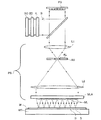
[0025] 図1は本発明の一実施形態のリソグラフィ装置1を図で示す。この装置は、照明システムIL、パターニングデバイスPD、基板テーブルWT、および投影システムPSを備える。照明システム(イルミネータ)ILは、放射ビームB(例えばUV放射)を調整するよう構成されている。 FIG. 1 schematically depicts a lithographic apparatus 1 according to one embodiment of the invention. The apparatus comprises an illumination system IL, a patterning device PD, a substrate table WT, and a projection system PS. The illumination system (illuminator) IL is configured to condition a radiation beam B (eg, UV radiation).
[0026] パターニングデバイスPD(例えばレチクルすなわちマスク、または個別制御可能要素アレイ)はビームを変調する。通常、個別制御可能要素アレイは投影システムPSに対して位置が固定される。しかしそれに代わり、あるパラメータに従って個別制御可能要素アレイを正確に位置決めするために構成されたポジショナに接続されていてもよい。 [0026] A patterning device PD (eg, a reticle or mask, or an array of individually controllable elements) modulates the beam. Usually, the individually controllable element array is fixed in position relative to the projection system PS. However, it may instead be connected to a positioner configured to accurately position the individually controllable element array according to certain parameters.
[0027] 基板テーブルWTは、基板(例えばレジストでコートされた基板)Wを支持するよう構成されており、あるパラメータに従って基板を正確に位置決めするために構成されたポジショナPWに接続されている。 The substrate table WT is configured to support a substrate (eg, a substrate coated with resist) W and is connected to a positioner PW configured to accurately position the substrate according to certain parameters.
[0028] 投影システム(例えば屈折投影レンズシステム)PSは、個別制御可能要素アレイによって変調された放射ビームを基板Wのターゲット部分C(例えば1つまたは複数のダイを含む)に投影するよう構成されている。 [0028] The projection system (eg, refractive projection lens system) PS is configured to project the radiation beam modulated by the individually controllable element array onto a target portion C (eg, including one or more dies) of the substrate W. ing.
[0029] 照明システムは、放射を誘導、整形、または制御するために、屈折光学部品、反射光学部品、磁気的光学部品、電磁気的光学部品、静電的光学部品または他の種類の光学部品などの種々の光学部品、あるいはこれらの組合せを含むことができる。 [0029] The illumination system may be a refractive optical component, a reflective optical component, a magnetic optical component, an electromagnetic optical component, an electrostatic optical component or other type of optical component to induce, shape or control radiation, etc. Various optical components, or combinations thereof.
[0030] 本明細書において用いる「パターニングデバイス」または「コントラストデバイス」という用語は、例えば基板のターゲット部分にパターンを生成するなど、放射ビーム断面を変調するのに用い得るどのようなデバイスをも指すように広く解釈されるべきである。これらのデバイスは静的パターニングデバイス(例えばマスクやレチクル)であってもよいし、動的パターニングデバイス(例えばプログラマブル要素配列)であってもよい。簡潔にするために、説明のほとんどは動的パターニングデバイスの観点でなされるが、本発明の範囲を逸脱することなく静的パターニングデバイスを用いることも可能であることを理解されたい。 [0030] As used herein, the term "patterning device" or "contrast device" refers to any device that can be used to modulate a radiation beam cross section, eg, to generate a pattern in a target portion of a substrate. Should be interpreted widely. These devices may be static patterning devices (eg, masks or reticles) or dynamic patterning devices (eg, programmable element arrays). For brevity, most of the description is in terms of a dynamic patterning device, but it should be understood that a static patterning device may be used without departing from the scope of the present invention.
[0031] 放射ビームに与えられるパターンは、例えば、放射ビームのパターンが位相シフトフィーチャあるいは所謂アシストフィーチャを含む場合には、基板のターゲット部分に所望されるパターンと厳密に対応していなくてもよいことに留意されたい。同じく、基板に最終的に形成されるパターンは、個別制御可能要素アレイ上に形成されるパターンにどの時点においても対応しなくてもよい。このような事態は、基板の各部に形成される最終的なパターンが所定時間または所定回数の露光の重ね合わせにより形成され、かつこの所定の露光中に個別制御可能要素アレイ上のパターンおよび/または基板の相対位置が変化する場合に起こり得る。 [0031] The pattern imparted to the radiation beam may not correspond exactly to the pattern desired for the target portion of the substrate, for example, if the pattern of the radiation beam includes phase shift features or so-called assist features. Please note that. Similarly, the pattern finally formed on the substrate may not correspond to the pattern formed on the individually controllable element array at any point in time. Such a situation is that the final pattern formed on each part of the substrate is formed by overlaying a predetermined time or a predetermined number of exposures, and the pattern on the individually controllable element array and / or during this predetermined exposure. This can happen when the relative position of the substrate changes.
[0032] 通常、基板のターゲット部分に生成されるパターンは、そのターゲット部分に生成されるデバイス、例えば集積回路やフラットパネルディスプレイの特定の機能層に対応する(例えばフラットパネルディスプレイのカラーフィルタ層や薄膜トランジスタ層)。そのようなパターニングデバイスの例には、レチクル、プログラマブルミラーアレイ、レーザダイオードアレイ、LEDアレイ、グレーティングライトバルブ、およびLCDアレイなどがある。 [0032] Usually, the pattern generated in the target portion of the substrate corresponds to a specific functional layer of a device generated in the target portion, such as an integrated circuit or a flat panel display (for example, a color filter layer of a flat panel display, Thin film transistor layer). Examples of such patterning devices include reticles, programmable mirror arrays, laser diode arrays, LED arrays, grating light valves, and LCD arrays.
[0033] 電子的手段(例えばコンピュータ)によってパターンをプログラム可能であるパターニングデバイスは、例えば複数のプログラマブル要素を含むパターニングデバイス(例えば1つ前の文章に挙げたものでは、レチクルを除くすべてのものが該当する)であり、本明細書では総称して「コントラストデバイス」と呼ぶこととする。さまざまな実施例ではパターニングデバイスは少なくとも10個のプログラマブル要素を備え、または例えば少なくとも100個、少なくとも1,000個、少なくとも10,000個、少なくとも100,000個、少なくとも1,000,000個、または少なくとも10,000,000個のプログラマブル要素を備えてもよい。 [0033] A patterning device that is programmable by electronic means (eg, a computer) includes, for example, a patterning device that includes a plurality of programmable elements (eg, all but the reticle in the preceding sentence). In this specification, the term “contrast device” is used. In various embodiments, the patterning device comprises at least 10 programmable elements, or such as at least 100, at least 1,000, at least 10,000, at least 100,000, at least 1,000,000, or There may be at least 10,000,000 programmable elements.
[0034] プログラマブルミラーアレイは、粘弾性制御層と反射表面とを有するマトリックス状にアドレス指定可能な表面を備えてもよい。この装置の基本的原理は、例えば、反射表面のうちアドレス指定されている領域が入射光を回折光として反射し、他方、アドレス指定されていない領域が入射光を非回折光として反射するというものである。適切な空間フィルタを用いることにより、反射光ビームから非回折光を取り除いて回折光だけを基板に到達させるようにすることができる。このようにして、マトリックス状のアドレス指定可能表面にアドレス指定により形成されるパターンに従ってビームにパターンが付けられる。 [0034] The programmable mirror array may comprise a matrix-addressable surface having a viscoelastic control layer and a reflective surface. The basic principle of this device is that, for example, the addressed area of the reflective surface reflects incident light as diffracted light, while the non-addressed area reflects incident light as non-diffracted light. It is. By using an appropriate spatial filter, it is possible to remove non-diffracted light from the reflected light beam so that only the diffracted light reaches the substrate. In this way, the beam is patterned according to the pattern formed by addressing on the matrix-addressable surface.
[0035] 代替例として、フィルタにより回折光を取り除いて基板に非回折光を到達させるようにすることもできる。 As an alternative, diffracted light can be removed by a filter so that non-diffracted light reaches the substrate.
[0036] 同様にして回折光学MEMS(微小電気機械システム)デバイスアレイを用いることもできる。一例として、回折光学MEMSデバイスは、入射光を回折光として反射する回折格子を形成するよう変形される複数の反射性のリボン状部位(ribbons)を備える。 Similarly, a diffractive optical MEMS (micro electro mechanical system) device array can also be used. As an example, a diffractive optical MEMS device comprises a plurality of reflective ribbons that are deformed to form a diffraction grating that reflects incident light as diffracted light.
[0037] プログラマブルミラーアレイの他の例では、マトリックス状微小ミラーの配列が用いられ、各微小ミラーは局所的に電界を適宜与えられることにより、または圧電作動手段を使用することにより各々が独立に軸周りに傾斜し得る。再度述べるが、ミラーはマトリックス状にアドレス指定可能に構成されており、アドレス指定されたミラーは入射する放射ビームをアドレス指定されていないミラーとは異なる方向に反射する。このようにしてマトリックス状のアドレス指定可能なミラーにより形成されるパターンに従って反射ビームにパターンが付けられ得る。必要とされるマトリックス状アドレス指定は、適した電子的手段を使用して実行することができる。 [0037] In another example of a programmable mirror array, an array of matrix-shaped micromirrors is used, and each micromirror is independently applied with a local electric field as appropriate, or by using piezoelectric actuation means. Can be tilted about an axis. Again, the mirrors are configured to be addressable in a matrix, and the addressed mirrors reflect the incoming radiation beam in a different direction than the non-addressed mirrors. In this way, the reflected beam can be patterned according to the pattern formed by the matrix-addressable mirrors. The required matrix addressing can be performed using suitable electronic means.
[0038] パターニングデバイスPDの他の例はプログラマブルLCDアレイである。 [0038] Another example of a patterning device PD is a programmable LCD array.
[0039] リソグラフィ装置は1つ以上のコントラストデバイスを備えることができる。例えば、リソグラフィ装置は、複数の個別制御可能要素アレイを有し、それぞれの要素が互いに独立に制御されるものとすることができる。このような構成では、個別制御可能要素アレイのうちのいくつかのアレイまたはすべてのアレイは、共通の照明光学システム(または照明光学システムの一部)、個別制御可能要素アレイのための共通サポート構造、および/または共通の投影システム(または投影システムの一部)の少なくとも1つを有してもよい。 [0039] The lithographic apparatus may comprise one or more contrast devices. For example, the lithographic apparatus may have a plurality of individually controllable element arrays, each element being controlled independently of each other. In such a configuration, some or all of the individually controllable element arrays may have a common illumination optical system (or part of the illumination optical system), a common support structure for the individually controllable element array. And / or at least one of a common projection system (or part of a projection system).
[0040] 一実施例では、図1に示す実施形態のように、基板Wは実質的に円形状であり、場合によっては周縁部にノッチおよび/または平坦端部を有していてもよい。一実施例では、基板は例えば長方形などの多角形形状でもよい。 In one example, as in the embodiment shown in FIG. 1, the substrate W is substantially circular and may optionally have a notch and / or a flat edge at the periphery. In one embodiment, the substrate may be a polygonal shape such as a rectangle.
[0041] 基板が実質的に円形の形状を有する実施例は、基板の直径が少なくとも25mm、または例えば少なくとも50mm、少なくとも75mm、少なくとも100mm、少なくとも125mm、少なくとも150mm、少なくとも175mm、少なくとも200mm、少なくとも250mm、または少なくとも300mmである例を含む。一実施形態では、基板の直径は最長でも500mm、最長でも400mm、最長でも350mm、最長でも300mm、最長でも250mm、最長でも200mm、最長でも150mm、最長でも100mm、または最長でも75mmである。 [0041] Examples in which the substrate has a substantially circular shape include a substrate diameter of at least 25 mm, or such as at least 50 mm, at least 75 mm, at least 100 mm, at least 125 mm, at least 150 mm, at least 175 mm, at least 200 mm, at least 250 mm, Or an example that is at least 300 mm. In one embodiment, the diameter of the substrate is at most 500 mm, at most 400 mm, at most 350 mm, at most 300 mm, at most 250 mm, at most 200 mm, at most 150 mm, at most 100 mm, or at most 75 mm.
[0042] 基板が例えば長方形などの多角形である実施例は、基板の少なくとも1辺の長さ、または例えば少なくとも2辺または少なくとも3辺の長さが、少なくとも5cmで、または例えば少なくとも25cm、少なくとも50cm、少なくとも100cm、少なくとも150cm、少なくとも200cm、または少なくとも250cmを有する例を含む。 [0042] Examples in which the substrate is a polygon, such as a rectangle, have a length of at least one side of the substrate, or, for example, a length of at least two sides or at least three sides of at least 5 cm, or such as at least 25 cm, at least Examples include 50 cm, at least 100 cm, at least 150 cm, at least 200 cm, or at least 250 cm.
[0043] 一実施例では、基板の少なくとも1辺の長さが、最長でも1000cm、または例えば最長でも750cm、最長でも500cm、最長でも350cm、最長でも250cm、最長でも150cm、または最長でも75cmである。 [0043] In one embodiment, the length of at least one side of the substrate is at most 1000 cm, or for example, at most 750 cm, at most 500 cm, at most 350 cm, at most 250 cm, at most 150 cm, or at most 75 cm .
[0044] 一実施例では、基板Wはウェーハであり、例えば半導体ウェーハである。一実施例ではウェーハ材料は、Si、SiGe、SiGeC、SiC、Ge、GaAs、InPおよびInAsから成る群から選択される。このウェーハは、III/V族化合物半導体ウェーハ、シリコンウェーハ、セラミック基板、ガラス基板、またはプラスチック基板である。この基板は(ヒトの裸眼で)透明であってもよいし、有色であってもよいし、無色であってもよい。 [0044] In one embodiment, the substrate W is a wafer, for example a semiconductor wafer. In one embodiment, the wafer material is selected from the group consisting of Si, SiGe, SiGeC, SiC, Ge, GaAs, InP and InAs. This wafer is a III / V compound semiconductor wafer, a silicon wafer, a ceramic substrate, a glass substrate, or a plastic substrate. This substrate may be transparent (with the naked human eye), colored or colorless.
[0045] この基板の厚さは例えば基板材料および/または基板寸法に応じてある程度変更され得る。一実施例では、基板の厚さは、少なくとも50μmであり、または例えば少なくとも100μm、少なくとも200μm、少なくとも300μm、少なくとも400μm、少なくとも500μm、または少なくとも600μmである。基板の厚さは、厚くても5000μm、例えば厚くても3500μm、厚くても2500μm、厚くても1750μm、厚くても1250μm、厚くても1000μm、厚くても800μm、厚くても600μm、厚くても500μm、厚くても400μm、または厚くても300μmである。 [0045] The thickness of the substrate may vary to some extent depending on, for example, the substrate material and / or substrate dimensions. In one example, the thickness of the substrate is at least 50 μm, or for example at least 100 μm, at least 200 μm, at least 300 μm, at least 400 μm, at least 500 μm, or at least 600 μm. The thickness of the substrate is 5000 μm at the maximum, for example, 3500 μm at the maximum, 2500 μm at the maximum, 1750 μm at the maximum, 1250 μm at the maximum, 1000 μm at the maximum, 800 μm at the maximum, 600 μm at the maximum. It is 500 μm, at most 400 μm, or at most 300 μm.
[0046] ここで言及する基板は、露光前または露光後において例えばトラック(典型的にはレジスト層を基板に塗布し、露光後のレジストを現像する装置)、メトロロジーツール、および/またはインスペクションツールにより処理されてもよい。一実施例ではレジスト層が基板に設けられる。 [0046] The substrate referred to herein may be, for example, a track (typically a device that applies a resist layer to the substrate and develops the resist after exposure), a metrology tool, and / or an inspection tool before or after exposure. May be processed. In one embodiment, a resist layer is provided on the substrate.
[0047] 本明細書で用いる「投影システム」という用語は、使用される露光光、あるいは液浸露光用液体や真空の利用などの他の要因に関して適切とされるいかなるタイプの投影システムをも包含するよう広く解釈されるべきであり、屈折光学システム、反射光学システム、反射屈折光学システム、磁気的光学システム、電磁気的光学システム、静電的光学システム、またはこれらの任意の組合せなどが含まれる。以下「投影レンズ」という用語は、より一般的な用語である「投影システム」という用語と同義的に用いられ得る。 [0047] As used herein, the term "projection system" encompasses any type of projection system that is appropriate for the exposure light used or other factors such as the use of immersion exposure liquids or vacuums. And includes refractive optical systems, reflective optical systems, catadioptric optical systems, magnetic optical systems, electromagnetic optical systems, electrostatic optical systems, or any combination thereof. Hereinafter, the term “projection lens” may be used interchangeably with the more general term “projection system”.
[0048] 投影システムは、個別制御可能要素アレイにおけるパターンが基板上にコヒーレントに形成されるように該パターンの像を形成し得る。これに代わり、投影システムは二次光源の像を形成してもよく、この場合個別制御可能要素アレイの各要素はシャッタとして動作してもよい。この場合には投影システムは、例えば二次光源を形成し基板上にスポット状に像形成するために、例えばマイクロレンズアレイ(MLAとして知られている)やフレネルレンズアレイなどのフォーカスのための要素のアレイを含んでもよい。一実施例ではフォーカスのための要素のアレイ(例えばMLA)は少なくとも10個のフォーカスのための要素を備え、または例えば少なくとも100個、少なくとも1,000個、少なくとも10,000個、少なくとも100,000個、または少なくとも1,000,000個のフォーカスのための要素を備えてもよい。一実施例では、パターニングデバイスにおける個別制御可能要素の数は、フォーカスのための要素のアレイにおけるフォーカスのための要素の数とは等しいか、より多い。一実施例では、フォーカスのための要素のアレイにおける1つ以上(例えばたいていは各アレイにつき1000以上)のフォーカスのための要素は、個別制御可能要素アレイにおける1つ以上(例えば2つ以上、または3つ以上、5つ以上、10以上、20以上、25以上、35以上、または50以上)の個別制御可能要素に光学的に連関していてもよい。一実施例では、MLAは、少なくとも基板に近づく方向および遠ざかる方向に例えば1以上のアクチュエータを用いて移動可能である。基板に近づく方向および遠ざかる方向にMLAを移動させることができる場合には、基板を動かさなくても、例えば焦点合わせをすることが可能となる。 [0048] The projection system may form an image of the pattern such that the pattern in the individually controllable element array is coherently formed on the substrate. Alternatively, the projection system may form an image of the secondary light source, in which case each element of the individually controllable element array may act as a shutter. In this case, the projection system, for example, forms a secondary light source and forms a spot image on the substrate, for example a focusing element such as a microlens array (known as MLA) or a Fresnel lens array. May include an array of In one embodiment, an array of elements for focus (eg, MLA) comprises at least 10 elements for focus, or, eg, at least 100, at least 1,000, at least 10,000, at least 100,000. Or at least 1,000,000 focus elements may be provided. In one embodiment, the number of individually controllable elements in the patterning device is equal to or greater than the number of elements for focus in the array of elements for focus. In one embodiment, one or more (eg, usually 1000 or more for each array) focus elements in the array of elements for focus may be one or more (eg, two or more) in the individually controllable element array, or 3 or more, 5 or more, 10 or more, 20 or more, 25 or more, 35 or more, or 50 or more) may be optically associated with the individually controllable elements. In one embodiment, the MLA can be moved, for example, using one or more actuators, at least in a direction toward and away from the substrate. When the MLA can be moved in a direction approaching and away from the substrate, for example, focusing can be performed without moving the substrate.
[0049] 図1および図2に示されるように本装置は反射型(例えば反射型の個別制御可能要素アレイを用いる)である。代替的には、透過型(例えば透過型個別制御可能要素アレイを用いる)の装置を用いてもよい。 [0049] As shown in FIGS. 1 and 2, the apparatus is reflective (eg, using a reflective individually controllable element array). Alternatively, a transmissive device (eg, using a transmissive individually controllable element array) may be used.
[0050] リソグラフィ装置は、2つ(デュアルステージ)以上の基板テーブルを備えるタイプのものとすることができる。このような「マルチステージ」の装置では、追加されたテーブルを並行して使用さすることができ、あるいは1以上のテーブルで露光が行われている間に1以上の他のテーブルで準備工程が実行されるようにすることができる。 [0050] The lithographic apparatus may be of a type comprising two (dual stage) or more substrate tables. In such a “multi-stage” apparatus, the added tables can be used in parallel, or the preparation process is performed at one or more other tables while the exposure is being performed at one or more tables. Can be executed.
[0051] リソグラフィ装置は、基板の少なくとも一部が比較的高い屈折率を有する例えば水などの「液浸液」で被覆されて、投影システムと基板との間の空隙を充填するタイプのものとすることができる。液浸液は、例えばパターニングデバイスと投影システムとの間などのリソグラフィ装置の他の空間に適用されるものとすることもできる。液浸技術は投影システムの開口数を増大させる技術として周知である。本明細書では「液浸」という用語は、基板等の構造体が液体に完全に浸されているということを意味するのではなく、露光時に投影システムと基板との間に液体が存在するということを意味するに過ぎない。 [0051] The lithographic apparatus is of a type wherein at least a portion of the substrate is coated with an "immersion liquid" such as water having a relatively high refractive index to fill a gap between the projection system and the substrate. can do. An immersion liquid may also be applied to other spaces in the lithographic apparatus, for example, between the patterning device and the projection system. Immersion techniques are well known as techniques for increasing the numerical aperture of projection systems. As used herein, the term “immersion” does not mean that a structure such as a substrate is completely immersed in liquid, but that liquid exists between the projection system and the substrate during exposure. It just means that.
[0052] 再度図1を参照すると、イルミネータILは放射源SOから放射ビームを受け取る。一実施例では、放射源は少なくとも5nm、例えば少なくとも10nm、少なくとも11〜30nm、少なくとも50nm、少なくとも100nm、少なくとも150nm、少なくとも175nm、少なくとも200nm、少なくとも250nm、少なくとも275nm、少なくとも300nm、少なくとも325nm、少なくとも350nm、または少なくとも360nmの波長を有する放射を提供する。一実施例では、放射源SOにより生成される放射は、最長でも450nm、または例えば最長でも425nm、最長でも375nm、最長でも360nm、最長でも325nm、最長でも275nm、最長でも250nm、最長でも225nm、最長でも200nm、または最長でも175nmの波長を有する。一実施例では、この放射は、436nm、405nm、365nm、355nm、248nm、193nm、157nm、および/または126nmの波長を含む。一実施例では、この放射は365nm程度、または355nm程度の波長を含む。一実施例では、この放射は例えば365nm、405nm、および436nmの波長を含む広帯域の波長を含む。355nmの波長のレーザ光源を使用することができる。例えば光源がエキシマレーザである場合には、光源とリソグラフィ装置とは別体であってもよい。この場合、光源はリソグラフィ装置の一部を構成しているとはみなされなく、放射ビームは光源SOからイルミネータILへとビームデリバリシステムBDを介して受け渡される。ビームデリバリシステムBDは例えば適切な誘導ミラーおよび/またはビームエキスパンダを含んで構成される。あるいは光源が水銀ランプである場合には、光源はリソグラフィ装置に一体に構成されていてもよい。光源SOとイルミネータILとは、またビームデリバリシステムBDが必要とされる場合にはこれも合わせて、放射システムと総称される。 [0052] Referring again to FIG. 1, the illuminator IL receives a radiation beam from a radiation source SO. In one example, the radiation source is at least 5 nm, such as at least 10 nm, at least 11-30 nm, at least 50 nm, at least 100 nm, at least 150 nm, at least 175 nm, at least 200 nm, at least 250 nm, at least 275 nm, at least 300 nm, at least 325 nm, at least 350 nm, Or provide radiation having a wavelength of at least 360 nm. In one embodiment, the radiation generated by the source SO is at most 450 nm, or for example, at most 425 nm, at most 375 nm, at most 360 nm, at most 325 nm, at most 275 nm, at most 250 nm, at most 225 nm, at most But it has a wavelength of 200 nm, or at most 175 nm. In one example, the radiation includes wavelengths of 436 nm, 405 nm, 365 nm, 355 nm, 248 nm, 193 nm, 157 nm, and / or 126 nm. In one embodiment, the radiation includes a wavelength on the order of 365 nm, or on the order of 355 nm. In one example, the radiation includes broadband wavelengths including, for example, 365 nm, 405 nm, and 436 nm wavelengths. A laser light source with a wavelength of 355 nm can be used. For example, when the light source is an excimer laser, the light source and the lithographic apparatus may be separate. In this case, the light source is not considered to form part of the lithographic apparatus, and the radiation beam is passed from the light source SO to the illuminator IL via the beam delivery system BD. The beam delivery system BD comprises, for example, a suitable guiding mirror and / or beam expander. Alternatively, if the light source is a mercury lamp, the light source may be integrated with the lithographic apparatus. The light source SO and the illuminator IL are collectively referred to as a radiation system when a beam delivery system BD is required.
[0053] イルミネータILは放射ビームの角度強度分布を調整するためのアジャスタADを備えてもよい。一般にはイルミネータの瞳面における強度分布の少なくとも外側および/または内側半径範囲(通常それぞれ「σ-outer」および「σ-inner」と呼ばれる)が調整される。それに加えて、イルミネータILは、インテグレータINおよびコンデンサCOなどのさまざまな他の要素を備えてもよい。イルミネータはビーム断面における所望の均等性および強度分布を得るべく放射ビームを調整するのに用いられ得る。イルミネータILおよび追加の関連する構成要素は放射ビームを複数のサブビームに分割するように構成されていてもよい。例えば各サブビームが個別制御可能要素アレイの1つまたは複数の個別制御可能要素に対応するように構成してもよい。放射ビームをサブビームに分割するのに例えば二次元の回折格子を用いてもよい。本明細書においては「放射ビーム」という用語は、放射ビームがこれらの複数の放射のサブビームを含むという状況も包含されるが、これに限定されるものではない。 [0053] The illuminator IL may include an adjuster AD for adjusting the angular intensity distribution of the radiation beam. In general, at least the outer and / or inner radius range (commonly referred to as “σ-outer” and “σ-inner”, respectively) of the intensity distribution at the pupil plane of the illuminator is adjusted. In addition, the illuminator IL may comprise various other elements such as an integrator IN and a capacitor CO. The illuminator can be used to adjust the radiation beam to obtain the desired uniformity and intensity distribution in the beam cross section. The illuminator IL and the additional associated components may be configured to split the radiation beam into a plurality of sub-beams. For example, each sub-beam may be configured to correspond to one or more individually controllable elements of the individually controllable element array. For example, a two-dimensional diffraction grating may be used to split the radiation beam into sub-beams. As used herein, the term “radiation beam” includes, but is not limited to, situations in which the radiation beam includes sub-beams of these multiple radiations.
[0054] 放射ビームBは、パターニングデバイスPD(例えば、個別制御可能要素アレイ)に入射して、当該パターニングデバイスにより変調される。放射ビームBはパターニングデバイスPDにより反射され、投影システムPSを通過する。投影システムPSはビームを基板Wのターゲット部分Cにフォーカスさせる。ポジショナPWと位置センサIF2(例えば、干渉計デバイス、リニアエンコーダ、容量センサなど)により基板テーブルWTを正確に移動させることができる。基板テーブルWTは例えば放射ビームBの経路に異なる複数のターゲット部分Cをそれぞれ位置決めするように移動される。個別制御可能要素アレイ用の位置決め手段が使用される場合には、例えばスキャン中にビームBの経路に対してパターニングデバイスPDの位置を正確に補正するために用いられてもよい。 [0054] The radiation beam B is incident on the patterning device PD (eg, an array of individually controllable elements) and is modulated by the patterning device. The radiation beam B is reflected by the patterning device PD and passes through the projection system PS. The projection system PS focuses the beam on the target portion C of the substrate W. The substrate table WT can be accurately moved by the positioner PW and the position sensor IF2 (for example, an interferometer device, a linear encoder, a capacitance sensor, etc.). The substrate table WT is moved to position different target portions C in the path of the radiation beam B, for example. If positioning means for the individually controllable element array is used, it may be used, for example, to accurately correct the position of the patterning device PD with respect to the path of the beam B during the scan.
[0055] 一実施例では、ロングストロークモジュール(粗動位置決め)およびショートストロークモジュール(微動位置決め)により基板テーブルWTの移動を実現する。ロングストロークモジュールおよびショートストロークモジュールは図1には明示されていない。別の実施例ではショートストロークステージを省略してもよい。個別制御可能要素アレイを位置決めするためにも同様のシステムを用いることができる。必要な相対運動を実現するために、オブジェクトテーブルおよび/または個別制御可能要素アレイの位置を固定する一方、投射ビームBを代替的/追加的に移動可能としてもよいということも理解されるであろう。この構成は装置の大きさを小さくするのに役立ち得る。例えばフラットパネルディスプレイの製造に適用可能な更なる代替例として、基板テーブルWTおよび投影システムPSを固定し、基板Wを基板テーブルWTに対して移動させるように構成することができる。例えば基板テーブルWTは、実質的に一定の速度で基板Wをスキャンさせるためのシステムを備えることができる。 In one embodiment, the movement of the substrate table WT is realized by a long stroke module (coarse positioning) and a short stroke module (fine positioning). The long stroke module and the short stroke module are not explicitly shown in FIG. In another embodiment, the short stroke stage may be omitted. A similar system can be used to position the individually controllable element array. It will also be appreciated that the position of the object table and / or the individually controllable element array may be fixed while the projection beam B may be alternatively / additionally movable to achieve the required relative movement. Let's go. This configuration can help to reduce the size of the device. For example, as a further alternative applicable to the manufacture of flat panel displays, the substrate table WT and projection system PS may be fixed and configured to move the substrate W relative to the substrate table WT. For example, the substrate table WT can comprise a system for scanning the substrate W at a substantially constant speed.
[0056] 図1に示すように、放射ビームBは、放射ビームがまずビームスプリッタBSにより反射されてパターニングデバイスPDに入射するように構成されたビームスプリッタBSによってパターニングデバイスPDへ誘導することができる。ビームスプリッタを使わずに放射ビームBをパターニングデバイスに入射させるようにすることもできることも理解されたい。一実施形態では放射ビームは0度から90度の間の角度でパターニングデバイスに入射する。または、例えば5度から85度の間、15度から75度の間、25度から65度の間、または35度から55度の間の角度であってもよい(図1の実施形態は90度である)。パターニングデバイスPDは放射ビームBを変調し、再度ビームスプリッタBSに向かって戻るように放射ビームBを反射する。ビームスプリッタBSは変調されたビームを投影システムPSへと伝達する。しかし、放射ビームBをパターニングデバイスPDに入射させ、そのまま更に投影システムPSに入射させるという代替的な構成も可能であることも理解されよう。特に透過型のパターニングデバイスが用いられる場合には図1に示される構成は必要とはされない。 [0056] As shown in FIG. 1, the radiation beam B can be directed to the patterning device PD by a beam splitter BS configured such that the radiation beam is first reflected by the beam splitter BS and incident on the patterning device PD. . It should also be understood that the radiation beam B can be incident on the patterning device without using a beam splitter. In one embodiment, the radiation beam is incident on the patterning device at an angle between 0 and 90 degrees. Or, for example, an angle between 5 and 85 degrees, between 15 and 75 degrees, between 25 and 65 degrees, or between 35 and 55 degrees (the embodiment of FIG. Degrees). The patterning device PD modulates the radiation beam B and reflects the radiation beam B back towards the beam splitter BS again. The beam splitter BS transmits the modulated beam to the projection system PS. However, it will also be appreciated that alternative configurations are possible in which the radiation beam B is incident on the patterning device PD and further incident on the projection system PS. In particular, when a transmissive patterning device is used, the configuration shown in FIG. 1 is not required.
[0057] 図示の装置はいくつかのモードで使用することができる。 [0057] The depicted apparatus can be used in several modes.
[0058] 1.ステップモードでは、放射ビームに付けられたパターンの全体が1回の放射でターゲット部分Cに投影される間、個別制御可能要素アレイおよび基板は実質的に静止状態とされる(すなわち1回の静的露光)。次いで、基板テーブルWTがX方向および/またはY方向に移動されて、異なるターゲット部分Cが露光される。ステップモードでは、露光フィールドの最大サイズによって、1回の静的露光で結像されるターゲット部分Cの寸法が制限される。 [0058] In step mode, the individually controllable element array and the substrate are substantially stationary (i.e., a single static) while the entire pattern applied to the radiation beam is projected onto the target portion C with a single radiation. Exposure). The substrate table WT is then moved in the X direction and / or Y direction to expose a different target portion C. In step mode, the maximum size of the exposure field limits the size of the target portion C imaged in a single static exposure.
[0059] 2.スキャンモードでは、放射ビームに付けられたパターンがターゲット部分Cに投影される間、個別制御可能要素アレイおよび基板は同期してスキャンされる(すなわち1回の動的露光)。個別制御可能要素アレイに対する基板の速度および方向は、投影システムPSの拡大(縮小)特性および像反転特性により定められる。スキャンモードでは露光フィールドの最大サイズが1回の動的露光でのターゲット部分Cの(非スキャン方向の)幅を制限し、スキャン移動距離がターゲット部分の(スキャン方向の)長さを決定する。 [0059] 2. In scan mode, the individually controllable element array and the substrate are scanned synchronously (ie, one dynamic exposure) while the pattern applied to the radiation beam is projected onto the target portion C. The velocity and direction of the substrate relative to the individually controllable element array is determined by the enlargement (reduction) and image reversal characteristics of the projection system PS. In the scan mode, the maximum size of the exposure field limits the width (in the non-scan direction) of the target portion C in one dynamic exposure, and the scan movement distance determines the length (in the scan direction) of the target portion.
[0060] 3.パルスモードにおいて、個別制御可能要素アレイは実質的に静止状態のままにされ、パルス放射源により基板Wのターゲット部分Cにパターンの全体が投影される。基板テーブルWTが実質的に一定の速度で移動して、ビームBは基板W上を線状にスキャンさせられる。個別制御可能要素アレイ上のパターンは放射システムからのパルス間に必要に応じて更新される。パルス放射のタイミングは、基板W上の必要な場所で複数のターゲット部分Cが連続して露光されるように調整される。その結果、基板上の1つの短冊状領域にパターンが完全に露光されるようビームBにより基板Wがスキャンされることになる。そのプロセスを繰り返すことによって基板Wは完全に露光される。 [0060] 3. In the pulsed mode, the individually controllable element array remains substantially stationary and the entire pattern is projected onto the target portion C of the substrate W by the pulsed radiation source. As the substrate table WT moves at a substantially constant speed, the beam B is scanned linearly over the substrate W. The pattern on the individually controllable element array is updated as needed between pulses from the radiation system. The timing of the pulse radiation is adjusted so that a plurality of target portions C are continuously exposed at necessary locations on the substrate W. As a result, the substrate W is scanned by the beam B so that the pattern is completely exposed to one strip area on the substrate. By repeating the process, the substrate W is completely exposed.
[0061] 4.連続スキャンモードにおいては、変調された放射ビームBに対して基板Wが実質的に等速でスキャンされ、ビームBが基板W上をスキャンして露光するときに個別制御可能要素アレイ上のパターンが更新されることを除いて、基本的にパルスモードと同様である。個別制御可能要素アレイのパターンの更新に同期させるようにした、実質的に一定の放射源またはパルス放射源を用いることができる。 [0061] 4. In the continuous scan mode, the substrate W is scanned at a substantially constant speed with respect to the modulated radiation beam B, and the pattern on the individually controllable element array is scanned when the beam B scans and exposes the substrate W. It is basically the same as the pulse mode except that it is updated. A substantially constant radiation source or pulsed radiation source can be used that is synchronized to the update of the pattern of the individually controllable element array.
[0062] 5.ピクセルグリッド結像モードでは、基板Wに形成されるパターンはスポット状の露光を連続的に行うことにより実現される。このモードは図2のリソグラフィ装置を使用して実現することができる。このスポット状の露光はスポット発生器により形成され、スポット発生器はパターニングデバイスPDに適切に方向付けられて配置されている。スポット状の露光はそれぞれ実質的に同形状である。基板W上で露光スポットにより実質的に格子が描かれる。一実施例では、このスポットの寸法は描かれるピクセル格子のピッチよりも大きいが、露光スポットの格子の大きさよりもかなり小さい。描かれるスポットの強度を変化させることによりパターンが形成される。露光放射と露光放射との間にスポットの強度分布が変更される。 [0062] 5. In the pixel grid imaging mode, the pattern formed on the substrate W is realized by continuously performing spot-like exposure. This mode can be realized using the lithographic apparatus of FIG. This spot-shaped exposure is formed by a spot generator, and the spot generator is arranged so as to be appropriately oriented to the patterning device PD. Each spot-like exposure has substantially the same shape. A grating is substantially drawn on the substrate W by the exposure spot. In one embodiment, the spot size is larger than the pitch of the pixel grid being drawn, but much smaller than the grid size of the exposure spot. A pattern is formed by changing the intensity of the spot to be drawn. The intensity distribution of the spot is changed between the exposure radiation.
[0063] 上記で記載したモードを組み合わせて用いてもよいし、モードに変更を加えて用いてもよく、また全く別のモードで使用してもよい。 [0063] The modes described above may be used in combination, may be used by changing the mode, or may be used in a completely different mode.
[0064] 図5は本発明の別の実施形態のリソグラフィ装置を示す。上記図1および2と同様、図5の装置は照明システムIL、サポート構造MT、基板テーブルWT、および投影システムを備える。 [0064] Figure 5 depicts a lithographic apparatus according to another embodiment of the invention. Similar to FIGS. 1 and 2 above, the apparatus of FIG. 5 comprises an illumination system IL, a support structure MT, a substrate table WT, and a projection system.
[0065] 照明システムILは放射ビームB(例えば、水銀アークランプによって提供されるUV放射ビーム、あるいはKrFエキシマレーザまたはArFエキシマレーザによって生成されるDUV放射ビーム)を調整するように構成されている。 [0065] The illumination system IL is configured to condition a radiation beam B (eg, a UV radiation beam provided by a mercury arc lamp, or a DUV radiation beam generated by a KrF excimer laser or an ArF excimer laser).
[0066] サポート構造(例えばマスクテーブル)MTは、マスクパターンMPを有し、ある種のパラメータに従ってパターニングデバイスを正確に位置決めするように構成された第1のポジショナPMに接続されたパターニングデバイス(例えばマスク)MAを支持するように構成されている。 [0066] The support structure (eg, mask table) MT has a mask pattern MP and is connected to a first positioner PM (eg, a patterning device configured to accurately position the patterning device according to certain parameters) Mask) is configured to support MA.
[0067] 基板テーブルWTは、基板(例えばレジストコートウェーハ)Wを支持するよう構成されており、ある種のパラメータに従って基板を正確に位置決めするように構成された第2のポジショナPWに接続されている。 [0067] The substrate table WT is configured to support a substrate (eg, resist coated wafer) W and is connected to a second positioner PW configured to accurately position the substrate according to certain parameters. Yes.
[0068] 投影システム(例えば屈折投影レンズシステム)PSは、パターニングデバイスMAのパターンMPによって放射ビームBに付けられたパターンを基板Wのターゲット部分C(例えば1つまたは複数のダイからなる)に投影するよう構成されている。 [0068] The projection system (eg refractive refractive lens system) PS projects the pattern applied to the radiation beam B by the pattern MP of the patterning device MA onto a target portion C (eg consisting of one or more dies) of the substrate W. It is configured to
[0069] 照明システムILは、放射を誘導、整形、または制御するための、屈折光学素子、反射光学素子、あるいは回折の種類の光学素子などの各種の光学素子、またはこれらの組合せを含む。 [0069] The illumination system IL includes various optical elements, such as refractive optical elements, reflective optical elements, or diffractive optical elements, or combinations thereof, for directing, shaping, or controlling radiation.
[0070] サポート構造MTは、パターニングデバイスMAの重量を支持、すなわちそれに耐える。このサポート構造は、パターニングデバイスMAの配向、リソグラフィ装置のデザイン、および他の条件、例えば、パターニングデバイスMAが真空環境において保持されるか否かなどに依存するように、パターニングデバイスMAを保持する。サポート構造MTはフレームまたはテーブルであってよく、例えば、必要に応じて固定してもよいし、可動のものであってもよい。サポート構造MTは、パターニングデバイスMAが例えば投影システムPAに関して所望の位置にあることを保証する。本明細書において「レチクル」または「マスク」という用語を用いる場合、より一般的な用語「パターニングデバイス」と同義的であるとみなしてよい。 [0070] The support structure MT supports, ie bears, the weight of the patterning device MA. This support structure holds the patterning device MA in a manner that depends on the orientation of the patterning device MA, the design of the lithographic apparatus, and other conditions, such as for example whether or not the patterning device MA is held in a vacuum environment. The support structure MT may be a frame or a table. For example, the support structure MT may be fixed as necessary, or may be movable. The support structure MT ensures that the patterning device MA is at a desired position, for example with respect to the projection system PA. Any use of the terms “reticle” or “mask” herein may be considered synonymous with the more general term “patterning device”.
[0071] 上記のように、本明細書で用いられる用語「パターニングデバイス」は、基板のターゲット部分Cにパターンを生成するなど、放射ビームBにその断面にてパターンを付与するのに用い得るどのようなデバイスを指すように広く解釈されるべきである。例えばパターンMPが位相シフトフィーチャまたはいわゆるアシストフィーチャを含んでいる場合には、放射ビームBに付与されるパターンは基板Wのターゲット部分Cの所望のパターンに正確には対応しないことに留意されたい。全般的に、放射ビームBに付与されるパターンは、集積回路などのターゲット部分Cに形成されるデバイスの特定の機能層に相当する。 [0071] As noted above, the term "patterning device" as used herein refers to any pattern that can be used to impart a pattern in cross-section to the radiation beam B, such as creating a pattern in a target portion C of a substrate. Should be interpreted broadly to refer to such devices. Note that the pattern imparted to the radiation beam B does not exactly correspond to the desired pattern of the target portion C of the substrate W, for example if the pattern MP includes phase shift features or so-called assist features. In general, the pattern imparted to the radiation beam B corresponds to a particular functional layer of a device being formed in a target portion C, such as an integrated circuit.
[0072] 図5を参照すると、照明システムILは、例えばg−ラインまたはi−ラインUV放射を提供する水銀アークランプまたは270nm未満、例えば248、193、157および126nmの波長のDUV放射を提供するエキシマレーザといった放射源SOから放射ビームを受け取る。例えば放射源SOがエキシマレーザである場合、放射源SOおよびリソグラフィ装置は別個の実体であってよい。この場合、放射ビームBは例えば適切な誘導ミラーおよび/またはビームエキスパンダを備えるビームデリバリシステムBDを用いて放射源SOから照明システムILまで通される。その他の場合では、例えば放射源SOが水銀ランプの場合、放射源SOはリソグラフィ装置と一体であってよい。放射源SOおよび照明システムは、必要に応じてビームデリバリシステムBDと一緒に、放射システムと呼ばれ得る。 [0072] Referring to FIG. 5, the illumination system IL provides, for example, mercury arc lamps that provide g-line or i-line UV radiation or DUV radiation at wavelengths of less than 270 nm, such as 248, 193, 157 and 126 nm. A radiation beam is received from a radiation source SO, such as an excimer laser. For example, if the source SO is an excimer laser, the source SO and the lithographic apparatus may be separate entities. In this case, the radiation beam B is passed from the radiation source SO to the illumination system IL using, for example, a beam delivery system BD equipped with a suitable guiding mirror and / or beam expander. In other cases the source SO may be integral to the lithographic apparatus, for example when the source SO is a mercury lamp. The radiation source SO and the illumination system may be referred to as a radiation system, optionally together with a beam delivery system BD.
[0073] 照明システムILは放射ビームBの角度強度分布をマスクレベルで調整するためのアジャスタADを備えてもよい。一般には照明システムILの瞳IPUにおける強度分布の少なくとも外側および/または内側半径範囲(通常それぞれσ-outer、σ-innerと呼ばれる)が調整され得る。加えて照明システムILは、インテグレータINおよびコンデンサCOなどのさまざまな他の要素を備えてもよい。照明システムILはマスクレベルでビーム断面における所望の均等性および強度分布を得るように放射ビームBを調整するために用いられる。 [0073] The illumination system IL may include an adjuster AD for adjusting the angular intensity distribution of the radiation beam B at the mask level. In general, at least the outer and / or inner radius ranges (usually referred to as σ-outer and σ-inner, respectively) of the intensity distribution in the pupil IPU of the illumination system IL may be adjusted. In addition, the illumination system IL may comprise various other elements such as an integrator IN and a capacitor CO. The illumination system IL is used to adjust the radiation beam B to obtain the desired uniformity and intensity distribution in the beam cross section at the mask level.
[0074] 放射ビームBは、サポート構造(例えばマスクテーブルMT)上に保持されたパターニングデバイス(例えばマスクMA)に入射し、パターンMPに従ってパターニングデバイスMAによってパターニングされる。マスクMAを横断すると、放射ビームBは投影システムPSを通過し、投影システムがこのビームBを基板Wのターゲット部分C上にフォーカスさせる。 [0074] The radiation beam B is incident on the patterning device (eg, mask MA), which is held on the support structure (eg, mask table MT), and is patterned by the patterning device MA according to the pattern MP. When traversing the mask MA, the radiation beam B passes through the projection system PS, which focuses the beam B onto the target portion C of the substrate W.
[0075] 投影システムは照明システム瞳IPUと対になった瞳PPUを有する。放射の一部は強度分布の照明システム瞳IPUから出て、マスクパターンによる回折に影響されることなくマスクパターンを横断し、強度分布の像を照明システム瞳IPUに形成する。 [0075] The projection system has a pupil PPU paired with an illumination system pupil IPU. Part of the radiation exits the intensity distribution illumination system pupil IPU, traverses the mask pattern without being affected by the diffraction by the mask pattern, and forms an image of the intensity distribution on the illumination system pupil IPU.
[0076] 第2のポジショナPWと位置センサIF(例えば、干渉計デバイス、リニアエンコーダ、容量センサなど)により、例えば放射ビームBの経路において異なるターゲット部分を位置決めするように、基板テーブルWTを正確に移動させることができる。同じく、例えばマスクライブラリから機械的に検索した後あるいはスキャン中に、第1のポジショナPMおよび別の位置センサ(図5には明示せず)を用いて、放射ビームBの経路に対してマスクMAを正確に位置決めすることもできる。通常、マスクテーブルMTの移動は、第1のポジショナPMの一部を形成するロングストロークモジュール(粗動位置決め)およびショートストロークモジュール(微動位置決め)により実現される。同じく、基板テーブルWTの移動は、第2のポジショナPWの一部を形成するロングストロークモジュールおよびショートストロークモジュールを用いて実現される。(スキャナとは対照的に)ステッパの場合、マスクテーブルMTは、ショートストロークアクチュエータにのみに接続されてもよいし、固定されていてもよい。マスクMAおよび基板WはマスクアライメントマークM1、M2および基板アライメントマークP1、P2を用いて整列され得る。図示のように基板アライメントマークP1、P2は専用のターゲット部分を占めるが、ターゲット部分間の空隙(これらはスクライブレーンアライメントマークとして知られている)に設けられてもよい。同じく、2つ以上のダイがマスクMAに設けられている場合、マスクアライメントマークM1、M2はそのダイ間に設けられてよい。 [0076] The second positioner PW and position sensor IF (eg, interferometer device, linear encoder, capacitive sensor, etc.) accurately position the substrate table WT so as to position different target portions in the path of the radiation beam B, for example. Can be moved. Similarly, for example after mechanical retrieval from a mask library or during a scan, a mask MA is used for the path of the radiation beam B using a first positioner PM and another position sensor (not explicitly shown in FIG. 5). Can also be accurately positioned. Normally, the movement of the mask table MT is realized by a long stroke module (coarse positioning) and a short stroke module (fine positioning) that form a part of the first positioner PM. Similarly, the movement of the substrate table WT is realized by using a long stroke module and a short stroke module that form a part of the second positioner PW. In the case of a stepper (as opposed to a scanner) the mask table MT may be connected only to a short stroke actuator or may be fixed. Mask MA and substrate W may be aligned using mask alignment marks M1, M2 and substrate alignment marks P1, P2. As shown, the substrate alignment marks P1, P2 occupy dedicated target portions, but may be provided in the gaps between the target portions (these are known as scribe lane alignment marks). Similarly, if more than one die is provided on the mask MA, the mask alignment marks M1, M2 may be provided between the dies.
[0077] 図5の示す装置は以下のモードのうちの少なくとも1つで使用可能である。 [0077] The apparatus shown in FIG. 5 can be used in at least one of the following modes.
[0078] 1.ステップモードでは、放射ビームに付けられたパターンの全体が1回の放射でターゲット部分Cに投影される間、マスクテーブルMTおよび基板テーブルWTは実質的に静止状態とされる(すなわち1回の静的露光)。次いで、基板テーブルWTがX方向および/またはY方向に移動されて、異なるターゲット部分Cが露光され得る。ステップモードでは露光フィールドの最大サイズによって、1回の静的露光で結像されるターゲット部分Cの寸法が制限されることになる。 [0078] In step mode, the mask table MT and the substrate table WT are substantially stationary (i.e., a single static) while the entire pattern applied to the radiation beam is projected onto the target portion C with a single radiation. Exposure). The substrate table WT can then be moved in the X and / or Y direction so that a different target portion C can be exposed. In the step mode, the size of the target portion C imaged by one static exposure is limited by the maximum size of the exposure field.
[0079] 2.スキャンモードでは、放射ビームに付けられたパターンがターゲット部分Cに投影される間、マスクテーブルMTおよび基板テーブルWT板は同期してスキャンされる(すなわち1回の動的露光)。マスクテーブルMTに対する基板テーブルWTの速度および方向は、投影システムPSの拡大(縮小)特性および像反転特性により定められる。スキャンモードでは露光フィールドの最大サイズが1回の動的露光でのターゲット部分の(非スキャン方向の)幅を制限し、スキャン移動の距離がターゲット部分の(スキャン方向の)高さを決定する。 [0079] 2. In scan mode, the mask table MT and the substrate table WT plate are scanned synchronously (ie, one dynamic exposure) while the pattern applied to the radiation beam is projected onto the target portion C. The speed and direction of the substrate table WT relative to the mask table MT is determined by the enlargement (reduction) characteristics and image reversal characteristics of the projection system PS. In the scan mode, the maximum size of the exposure field limits the width (in the non-scan direction) of the target portion in one dynamic exposure, and the distance of the scan movement determines the height (in the scan direction) of the target portion.
[0080] 3.別のモードでは、マスクテーブルMTはプログラマブルパターニングデバイスを保持しながら実質的に静的に保持されたままにされ、基板テーブルWTは放射ビームに付与されるパターンがターゲット部分C上に投影されている間に移動またはスキャンされる。このモードでは通常、パルス放射源が用いられ、基板テーブルWTの各移動の後、またはスキャン中の連続する放射パルスの間に、必要に応じてプログラマブルパターニングデバイスが更新される。この動作モードは、上記タイプのプログラマブルミラーアレイなどのプログラマブルパターニングデバイスを用いたマスクレスリソグラフィに容易に適用可能である。 [0080] 3. In another mode, the mask table MT is held substantially static while holding the programmable patterning device, and the substrate table WT has a pattern imparted to the radiation beam projected onto the target portion C. Moved or scanned in between. In this mode, a pulsed radiation source is typically used and the programmable patterning device is updated as needed after each movement of the substrate table WT or during successive radiation pulses during the scan. This mode of operation can be readily applied to maskless lithography using a programmable patterning device such as a programmable mirror array of the type described above.
[0081] 上記で記載したモードを組み合わせて用いてもよいし、モードに変更を加えて用いてもよいし、あるいは全く別のモードで使用してもよい。 [0081] The modes described above may be used in combination, may be used by changing the mode, or may be used in a completely different mode.
[0082] リソグラフィでは基板上のレジスト層にパターンが露光される。そしてレジストが現像される。続いて追加の処理工程が基板に施される。基板の各部分へのこれらの追加の処理工程の作用は、レジストへの露光の程度によって異なる。特にこの処理は、所与のドーズ閾値を超える放射ドーズを受ける基板の部位が示す反応と、その閾値以下の放射ドーズを受けた部位が示す反応とが異なるように調整されている。例えば、エッチング工程においては上記の閾値を超える放射ドーズを受けた基板上の領域は、レジスト層が現像されることによりエッチングから保護される。一方、この閾値以下の放射ドーズを受けたレジストの部分は露光後の現像工程で除去され、基板のその領域はエッチングから保護されない。このため、所望のパターンがエッチングされることができる。特に、パターニングデバイス内の個別制御可能要素は、パターンフィーチャ内の基板上の領域に送られる放射が、該領域が露光中にドーズ閾値を越える放射ドーズを受けるように実質的に高い強度であるように、設定される。基板の他の領域は、ゼロまたはかなり低い放射強度を受けるように対応する個別制御可能要素が設定されることにより、ドーズ閾値以下の放射ドーズを受ける。 In lithography, a pattern is exposed on a resist layer on a substrate. Then, the resist is developed. Subsequently, additional processing steps are applied to the substrate. The effect of these additional processing steps on each part of the substrate depends on the degree of exposure to the resist. In particular, this process is adjusted so that the response exhibited by the portion of the substrate that receives a radiation dose that exceeds a given dose threshold is different from the response exhibited by a portion that receives a radiation dose below that threshold. For example, in the etching process, a region on the substrate that has received a radiation dose exceeding the above threshold is protected from etching by developing the resist layer. On the other hand, the portion of the resist that has received a radiation dose below this threshold is removed in the development step after exposure, and that region of the substrate is not protected from etching. For this reason, a desired pattern can be etched. In particular, the individually controllable elements in the patterning device are such that the radiation delivered to the area on the substrate in the pattern feature is substantially high intensity so that the area undergoes a radiation dose that exceeds the dose threshold during exposure. To be set. Other areas of the substrate receive a radiation dose below the dose threshold by setting the corresponding individually controllable elements to receive zero or a much lower radiation intensity.
[0083] 実際には、パターンフィーチャの端部での放射ドーズは、たとえフィーチャ境界の一方の側に最大放射強度、他方の側に最小放射強度を与えるように個別制御可能要素が設定されるとしても、所与の最大ドーズからゼロドーズへと急激に変化するわけではない。その代わりに、回折の影響により、放射ドーズのレベルは移行領域に渡って低下するからである。パターンフィーチャの境界の位置は、最終的に現像されたレジストにより形成される。その境界位置は、放射されたドーズが放射ドーズ閾値を下回る位置によって定められる。この移行領域でのドーズ低下のプロファイル、故にパターンフィーチャの境界の正確な位置は、パターンフィーチャ境界上または近傍に位置する基板上の各点に放射を与える個別制御可能要素の設定により、より正確に制御できる。これらは、最大強度レベルまたは最小強度レベルに対してだけではなく、最大強度レベルおよび最小強度レベルの間の強度レベルに対しても同様である。これは通常「グレイスケーリング」と呼ばれる。 [0083] In practice, the radiation dose at the edge of the pattern feature is set as an individually controllable element that gives maximum radiation intensity on one side of the feature boundary and minimum radiation intensity on the other side. However, it does not change rapidly from a given maximum dose to zero dose. Instead, due to diffraction effects, the radiation dose level decreases across the transition region. The position of the pattern feature boundary is formed by the finally developed resist. The boundary position is determined by the position where the emitted dose is below the emission dose threshold. The dose reduction profile in this transition region, and hence the exact location of the pattern feature boundary, is more accurately set by setting individually controllable elements that emit radiation to each point on the substrate located on or near the pattern feature boundary. Can be controlled. These are not only for the maximum or minimum intensity level, but also for the intensity level between the maximum and minimum intensity levels. This is commonly referred to as “gray scaling”.
[0084] グレイスケーリングは、所与の個別制御可能要素により基板に与えられる放射強度が2値に設定されるだけ(例えば最大値と最小値だけ)のリソグラフィシステムにおいて可能であるよりも、より良好なパターンフィーチャ境界の位置の制御を与える。一実施形態では、少なくとも3種類の異なる放射強度値が基板に投影されることができ、例えば少なくとも4種類の放射強度値、少なくとも8種類の放射強度値、少なくとも16種類の放射強度値、少なくとも32種類の放射強度値、少なくとも64種類の放射強度値、少なくとも128種類の放射強度値、または少なくとも256種類の放射強度値とすることもできる。 [0084] Gray scaling is better than is possible in a lithography system in which the radiation intensity imparted to a substrate by a given individually controllable element is only set to a binary value (eg only a maximum value and a minimum value) Give control of the location of the pattern feature boundaries. In one embodiment, at least three different radiant intensity values can be projected onto the substrate, eg, at least four radiant intensity values, at least eight radiant intensity values, at least sixteen radiant intensity values, at least 32. There can also be at least 64 radiant intensity values, at least 128 radiant intensity values, or at least 256 radiant intensity values.
[0085] グレイスケーリングは、上述の目的に加えてまたは上述の目的に代えて使用できることを理解されたい。例えば、露光後の基板の処理は、受けた放射ドーズレベルに応じて、基板の各領域の2つ以上の潜在的な反応があるように、調整することができる。例えば、第1の閾値以下の放射ドーズを受けた基板の部位では第1の種類の反応が生じ、第1の閾値以上であるが第2の閾値以下の放射ドーズを受けた基板の部位では第2の種類の反応が生じ、第2の閾値以上の放射ドーズを受けた基板の部位では第3の種類の反応が生じる。したがって、グレイスケーリングは、2以上の望ましいドーズレベルを有する基板に渡った放射ドーズプロファイルを与えるのに用いることができる。一実施形態では、放射ドーズプロファイルは少なくとも2つの所望のドーズレベルを有し、例えば少なくとも3つの所望の放射ドーズレベル、少なくとも4つの所望の放射ドーズレベル、少なくとも6つの所望の放射ドーズレベル、または少なくとも8つの所望の放射ドーズレベルを有する。 [0085] It should be understood that grayscaling can be used in addition to or in place of the above purposes. For example, the processing of the substrate after exposure can be tailored so that there are two or more potential reactions in each region of the substrate, depending on the radiation dose level received. For example, a first type of reaction occurs at a portion of the substrate that has received a radiation dose that is less than or equal to a first threshold, and a portion of the substrate that has received a radiation dose that is greater than or equal to the first threshold but less than or equal to a second threshold. Two types of reactions occur, and a third type of reaction occurs at the portion of the substrate that has received a radiation dose greater than or equal to the second threshold. Thus, gray scaling can be used to provide a radiation dose profile across a substrate having a desired dose level of 2 or more. In one embodiment, the radiation dose profile has at least two desired dose levels, such as at least three desired radiation dose levels, at least four desired radiation dose levels, at least six desired radiation dose levels, or at least Eight desired radiation dose levels.
[0086] 放射ドーズプロファイルは、上記のように、基板上の各点が受ける放射強度を単に制御すること以外の方法によっても制御できることをさらに理解されたい。例えば、基板上の各点が受ける放射ドーズは、各点への露光時間を制御することによっても代替的にまたは追加的に制御することができる。更なる例としては、基板上の各点は、潜在的に連続的な複数の露光にて放射を受けることができる。したがって、各点が受けた放射ドーズは、連続的複数露光のうちの選択されたサブセットを用いて点を露光することにより代替的にまたは追加的に制御することが可能となる。 [0086] It should be further understood that the radiation dose profile can be controlled by methods other than merely controlling the radiation intensity received at each point on the substrate, as described above. For example, the radiation dose experienced by each point on the substrate can alternatively or additionally be controlled by controlling the exposure time for each point. As a further example, each point on the substrate can receive radiation in multiple potentially sequential exposures. Thus, the radiation dose received by each point can be controlled alternatively or additionally by exposing the point with a selected subset of successive multiple exposures.
[0087] 基板上に要求されるパターンを形成するためには、パターニングデバイスにおける各個別制御可能要素を、露光処理中の各段階で必要な状態に設定する必要がある。よって、この必要状態を表す制御信号が各個別制御可能要素に伝達されなければならない。一実施例では、リソグラフィ装置は、制御信号を生成するコントローラを含む。基板に形成されるべきパターンは、例えばGDSIIなどのベクトルで規定されるフォーマットでリソグラフィ装置に与えられることができる。デザイン情報を各個別制御可能要素用の制御信号に変換するために、コントローラは、1つ以上のデータ操作デバイスを含む。各データ操作デバイスは、パターンを表すデータストリーム上の処理ステップを実行するように構成されている。データ操作デバイスは「データパス」とも総称される。 [0087] In order to form the required pattern on the substrate, each individually controllable element in the patterning device needs to be set to the required state at each stage during the exposure process. Therefore, a control signal representing this necessary state must be transmitted to each individually controllable element. In one embodiment, the lithographic apparatus includes a controller that generates the control signal. The pattern to be formed on the substrate can be provided to the lithographic apparatus in a format defined by a vector such as GDSII. In order to convert the design information into control signals for each individually controllable element, the controller includes one or more data manipulation devices. Each data manipulation device is configured to perform processing steps on the data stream representing the pattern. Data manipulation devices are also collectively referred to as “data paths”.
[0088] このデータパスのデータ操作デバイスは、次に示す機能の1つ以上を実行するように構成されることができる。ベクトルベースデザイン情報をビットマップのターンデータに変換すること、ビットマップパターンデータを必要とされる放射ドーズマップ(例えば基板に渡って必要とされる放射ドーズプロファイル)に変換すること、および、必要とされる放射ドーズマップを各個別制御可能要素のための必要放射強度値に変換すること、および、各個別制御可能要素のための必要放射強度値を対応する制御信号に変換すること。 [0088] The data manipulation device of this data path may be configured to perform one or more of the following functions. Converting vector-based design information into bitmap turn data, converting bitmap pattern data into the required radiation dose map (eg, the radiation dose profile required across the substrate), and Converting a radiated dose map to a required radiant intensity value for each individually controllable element and converting a required radiant intensity value for each individually controllable element into a corresponding control signal.
[0089] 図2は、例えばフラットパネルディスプレイの製造に用いることができる本発明の装置の構成を示す。図1および図5に示される構成要素に対応するものには図2においても同じ参照符号を付している。また、種々の実施形態の上記説明、例えば基板、パターニングデバイス、MLA、放射ビームなどの種々の構成も同様に適用可能である。 FIG. 2 shows the configuration of the apparatus of the present invention that can be used, for example, in the manufacture of flat panel displays. Components corresponding to those shown in FIGS. 1 and 5 are denoted by the same reference numerals in FIG. Also, the above descriptions of various embodiments, such as various configurations such as substrates, patterning devices, MLA, radiation beams, etc. are equally applicable.
[0090] 図2に示すように、投影システムPSは、2つのレンズL1、L2を備えるビームエキスパンダを含む。第1のレンズL1は、変調された放射ビームBを受け、開口絞りASの開口部でフォーカスさせる。開口部には他のレンズALを設けてもよい。そして放射ビームBは分岐し、第2のレンズL2(例えばフィールドレンズ)によりフォーカスされる。 [0090] As shown in FIG. 2, the projection system PS includes a beam expander including two lenses L1, L2. The first lens L1 receives the modulated radiation beam B and focuses it at the opening of the aperture stop AS. Another lens AL may be provided in the opening. The radiation beam B is branched and focused by a second lens L2 (for example, a field lens).
[0091] 投影システムPSは、拡大された変調放射ビームBを受けるように構成されているレンズアレイMLAを更に備える。変調放射ビームBの異なる部分はそれぞれレンズアレイMLAの異なる部分を通過する。この変調放射ビームBの異なる部分は、パターニングデバイスPDの1以上の個別制御可能要素アレイに対応している。各レンズは変調放射ビームBの各部分を基板W上の点にフォーカスさせる。このようにして基板W上に放射スポットSのアレイが露光される。図示のレンズアレイには8つのレンズ14が示されているだけであるが、レンズアレイは数千のレンズを含んでもよい(パターニングデバイスPDとして用いられる個別制御可能要素アレイについても同様である)。 [0091] The projection system PS further comprises a lens array MLA configured to receive the expanded modulated radiation beam B. Different parts of the modulated radiation beam B pass through different parts of the lens array MLA, respectively. The different parts of this modulated radiation beam B correspond to one or more individually controllable element arrays of the patterning device PD. Each lens focuses each portion of the modulated radiation beam B at a point on the substrate W. In this way, an array of radiation spots S is exposed on the substrate W. Although only eight lenses 14 are shown in the illustrated lens array, the lens array may include thousands of lenses (as well as an individually controllable element array used as the patterning device PD).
[0092] 図3は、本発明の一実施形態による、図2のシステムを用いて基板W上にどのようにパターンが生成されるのかを模式的に示す。図中の黒丸は、投影システムPSのレンズアレイMLAによって基板Wに投影されるスポットSのアレイを示す。基板Wは、基板W上での露光が進むにつれて投影システムPSに対してY方向に移動する。図中の白丸は、基板W上で既に露光されている露光スポットSEを示す。図示のように、投影システムPSのレンズアレイによって基板に投影された各スポットは基板W上に露光スポット列Rを露光により形成する。各スポットSの露光により形成される露光スポットSEの列Rがすべて合わさって、基板にパターンが完全に形成される。上記のようにこのような方式は一般に「ピクセルグリッド結像」(”pixel grid imaging”)と称される。 [0092] FIG. 3 schematically illustrates how a pattern is generated on a substrate W using the system of FIG. 2, according to one embodiment of the invention. Black circles in the figure indicate an array of spots S projected onto the substrate W by the lens array MLA of the projection system PS. The substrate W moves in the Y direction with respect to the projection system PS as exposure on the substrate W proceeds. White circles in the figure indicate exposure spots SE that have already been exposed on the substrate W. As illustrated, each spot projected onto the substrate by the lens array of the projection system PS forms an exposure spot row R on the substrate W by exposure. All the rows R of exposure spots SE formed by exposure of the spots S are combined to completely form a pattern on the substrate. As described above, such a method is generally referred to as “pixel grid imaging”.
[0093] 放射スポットSのアレイが基板Wに対して角度θをなして配置されている様子が示されている(基板の端部はそれぞれX方向およびY方向に平行である)。これは、基板がスキャン方向(Y方向)に移動するときに、各放射スポットが基板の異なる領域を通過するようにするためである。これにより、放射スポット15の配列により基板の全領域がカバーされることになる。一実施例では、角度θは最大で20°または10°であり、例えば最大で5°、最大で3°、最大で1°、最大で0.5°、最大で0.25°、最大で0.10°、最大で0.05°、または最大で0.01°である。一実施例では、角度θは最小で0.001°である [0093] A state in which the array of radiation spots S is arranged at an angle θ with respect to the substrate W is shown (the ends of the substrate are parallel to the X direction and the Y direction, respectively). This is because each radiation spot passes through a different region of the substrate when the substrate moves in the scanning direction (Y direction). As a result, the entire area of the substrate is covered by the arrangement of the radiation spots 15. In one embodiment, the angle θ is at most 20 ° or 10 °, for example at most 5 °, at most 3 °, at most 1 °, at most 0.5 °, at most 0.25 °, at most 0.10 °, 0.05 ° at the maximum, or 0.01 ° at the maximum. In one embodiment, the angle θ is a minimum of 0.001 °.
[0094] 図4は、本発明の一実施形態において、どのようにしてフラットパネルディスプレイの基板W全体が複数の光学エンジンを用いて1回のスキャンで露光され得るのかを模式的に示す。この例では、放射スポットSの8つのアレイSAが8つの光学エンジン(図示せず)により形成される。この光学エンジンは「チェス盤」(“chess board”)の構成のように2つの列R1、R2に配置されている。放射スポット(例えば図3のスポットS)のアレイの端部が隣接の放射スポットアレイの端部に(スキャン方向Yにおいて)少し重なるように形成される。一実施例において、光学エンジンは少なくとも3列、例えば4列または5列に配列される。このようにして、放射帯が基板Wの幅に渡って延び、1回のスキャンで基板全体の露光が可能となる。任意の数の光学エンジンを用いることができることを理解されたい。一実施例では、光学エンジンの数は少なくとも1個であり、例えば少なくとも2個、少なくとも4個、少なくとも8個、少なくとも10個、少なくとも12個、少なくとも14個、または少なくとも17個である。一実施例では、光学エンジンの数は40個未満であり、例えば30個未満または20個未満である。 FIG. 4 schematically illustrates how the entire substrate W of the flat panel display can be exposed in a single scan using multiple optical engines in one embodiment of the present invention. In this example, eight arrays SA of radiation spots S are formed by eight optical engines (not shown). The optical engine is arranged in two rows R1, R2 like a “chess board” configuration. The end of the array of radiation spots (eg, spot S in FIG. 3) is formed so as to slightly overlap the end of the adjacent radiation spot array (in the scanning direction Y). In one embodiment, the optical engines are arranged in at least 3 rows, for example 4 rows or 5 rows. In this way, the radiation band extends over the width of the substrate W, and the entire substrate can be exposed in one scan. It should be understood that any number of optical engines can be used. In one embodiment, the number of optical engines is at least one, for example at least 2, at least 4, at least 8, at least 10, at least 12, at least 14, or at least 17. In one embodiment, the number of optical engines is less than 40, for example less than 30 or less than 20.
[0095] 各光学エンジンは、上記のような、別個の照明システムIL、パターニングデバイスPD、および投影システムPSを備えることができる。しかし、2個以上の光学エンジンが1以上の照明システム、パターニングデバイス、および投影システムの少なくとも一部を共有することもできる。 [0095] Each optical engine may comprise a separate illumination system IL, patterning device PD, and projection system PS as described above. However, two or more optical engines can share at least a portion of one or more illumination systems, patterning devices, and projection systems.
[0096] 図6はリソグラフィ装置の一部、例えば図1、2または5のリソグラフィ装置の1つの一部分を示す。このリソグラフィ装置の一部分は、回折パターニングデバイス600と、アテニュエータ630、アパーチャストップASおよび光学デバイスOを含んだ投影システムPSと、基板Wとを備える。回折パターニングデバイス600は、2極照明604からパターニングされたビーム602を生成する。本発明の範囲から逸脱しなければ、ビーム604用の他の照明モード、例えば上記の他の照明モードを用いることもできる。パターニングされたビーム602は、投影システム瞳606(図5の瞳PPUも参照されたい)に沿って位置決めされたアテニュエータ630で受け取られる。
[0096] FIG. 6 shows a part of a lithographic apparatus, for example one part of the lithographic apparatus of FIG. A part of this lithographic apparatus comprises a
[0097] 2極(ダイポール)照明604を用いる場合、2極照明604の2つの部分604−Aおよび604−B(それぞれ実線および点線で示す)が回折パターニングデバイス600に衝突する。回折パターニングデバイスはゼロ(0)回折次数部分608−Aおよび608−B、+/−の第1回折次数部分610−Aおよび610−B、ならびに+/−のより高い回折次数部分(図示せず)を形成する。図示の例では、パターニングされたビーム602のゼロ回折次数部分608−Aおよび608−Bは、アテニュエータ630の減衰領域632(例えば減衰リング)によって減衰され、パターニングされたビーム602−Aおよび602−Bの第1回折次数部分610−Aおよび610−Bの第1の部分は、減衰されずにアテニュエータ630の開口、例えばアパーチャストップASを通過する。第1回折次数部分610−Aおよび610−Bの第2の部分は、瞳606を通過しない。このパターニングされたビーム602のアテニュエータ630との相互作用によって、部分的に減衰されたパターニングされたビーム602’が形成される。減衰されたゼロ次部分608’(AおよびBは示さず)および第1回折次数部分610(AおよびBは示さず)(部分的に減衰されたパターニングされたビーム602’)は、光学エレメントOにて受け取られる。光学エレメントOは、部分的に減衰されたパターニングされたビーム602’を基板Wのターゲット部分上に誘導する。
When using
[0098] 図示のように、パターニングされたビーム602−Aのゼロ回折次数部分608Aおよび第1の2極604−Aの第1回折次数ビーム610−Aの一部分は、瞳606の両側へ誘導される。同じく、パターニングされたビーム602−Bのゼロ回折次数部分608−Bおよび第2の2極604−Bの第1回折次数ビーム610−Bの一部分は、瞳606の両側へ誘導される。これによって、パターニングされたビーム602−Aのゼロ回折次数部分608−Aは、第1回折次数ビーム610−Bの一部分と隣接することが可能となり、逆もまた同じになる。この図において、パターニングされたビームのゼロ回折次数部分と第1回折次数部分との間の空間は説明のためのものであって、原寸大ではないかもしれない。また、隣接しているパターニングされたビームのゼロ回折次数部分と第1回折次数部分は典型的には、最大分解能の状況にのみ当てはまる。あるいは、分解能が変われば、ビームの角度が変わり、パターニングされたビームのゼロ回折次数部分と第1回折次数部分は最早隣接しないであろう。
[0098] As shown, the zero diffraction order portion 608A of the patterned beam 602-A and a portion of the first diffractive first beam 610-A of the first dipole 604-A are directed to both sides of the
[0099] 一実施例では、投影システムPSの瞳606は光学エレメント、例えばレンズ等を含んでよい(図9および以下の考察を参照)。
[0099] In one example, the
[0100] 回折パターニングデバイス600は、図1または2のパターニングデバイスPDとして、あるいは図5のマスクMAとして使用することができる。したがって、回折パターニングデバイス600は上記で詳細に考察したように、動的または静的パターニングデバイスとすることができる。使用される回折パターニングデバイス600の種類に応じて、パターニングされたビーム602の各回折次数部分は、瞳606のその対応する位置に達するときに、異なる強度またはエネルギーを有し得る。例えば、バイナリパターニングデバイスが回折パターニングデバイス600として使用される場合、パターニングされたビーム602のゼロ回折次数部分608は最も大きいエネルギーを有し、パターニングされたビーム602の第1回折次数部分610が次に大きなエネルギーを有し、その他のより高い回折次数部分のエネルギーがそれに続いて大きなエネルギーを有する。あるいは、位相シフトパターニングデバイスが回折パターニングデバイス600として使用される場合、パターニングされたビーム602の第1回折次数部分610およびより高い回折次数部分は、パターニングされたビーム602のゼロ回折次数部分608よりも大きなエネルギーを有する。しかし、パターニングされたビーム602の全次数は実質的に等しい強度を有することが好ましい。
[0100]
[0101] この減衰スキームを介して、パターニングされたビーム602の分解能は、部分的に減衰されたパターニングされたビーム602’において増大される。これは、ゼロ回折次数部分608に対してより大きな角度を有する第1およびそれ以上の回折次数部分はアパーチャストップASを通過するが、ゼロ回折次数部分608は実質的にそれらのエネルギーを均等化する端部636近傍を通過するためである。
[0101] Through this attenuation scheme, the resolution of the patterned
[0102] 図7および8は種々のアテニュエータ730および830の代替構成を示す。代替的には、アテニュエータ730および830は、独立した要素とすることができ、あるいは投影システムPS内で既に使用されている光学エレメント上に形成されることもできる。上記のように、アテニュエータ730および830は、パターニングされたビーム602の異なる回折次数部分の強度を実質的に均等化させるのに用いられる。例えば、アテニュエータ730および830上の吸収材料として、ニッケルまたはクロム材料を用いることができる。
[0102] FIGS. 7 and 8 show alternative configurations of
[0103] 再度図7を参照すると、アテニュエータ730は、照明ビーム604が2極照明であり回折パターニングデバイス600がバイナリパターニングデバイスである場合に用いられるように構成されている。上記のようにこの構成では、パターニングされたビーム602のゼロ回折次数部分608はパターニングされたビーム602の第1回折次数部分610よりも大きなエネルギーを有する。このため、アテニュエータ730は、エネルギーが第1回折次数部分610に実質的に等しくなるようにゼロ回折次数部分608のエネルギーを低減させる減衰領域732を含む。
[0103] Referring again to FIG. 7, the
[0104] ここで図8を参照すると、代替アテニュエータ830は、照明ビーム604が2極照明であり、回折パターニングデバイス600が位相シフトパターニングデバイス(例えば減衰型位相シフトパターニングデバイス)である場合に用いられるように構成されている。上記のようにこの構成では、ゼロ回折次数部分608は第1回折次数部分610よりも低いエネルギーを有する。このため、アテニュエータ830は、エネルギーがゼロ回折次数部分608に実質的に等しくなるように第1回折次数部分610のエネルギーを低減させる領域834を有する。
[0104] Referring now to FIG. 8, an
[0105] 追加的に、あるいは代替的には、アテニュエータ830は、ゼロ回折次数部分608に対応する、(ビーム604の光の波長に対して)透過性である、すなわち(領域834の減衰に対して)減衰の弱い領域832を有してよい。これはゼロ回折次数部分608の減衰を制御しながら、第1回折次数部分610の減衰も制御するために行われてよい。
[0105] Additionally or alternatively, the
[0106] 追加的に、あるいは代替的には、アテニュエータ730および830は、段階的な減衰領域またはリング(図示せず)を有することができる。目段階的領域の各々は、アテニュエータの直径上を更に外側に動くときに増大または低減させる減衰量を有する。このようにして、各回折次数部分は、単一の回折次数部分のみを減衰するのに代わり、個々にかつ別個に減衰されることができる。また、この構成を用いる場合、ゼロ回折次数部分は所望の減衰を有するアテニュエータの一部分へ誘導されることができる。例えば、70%の減衰が望ましい場合、ゼロ回折次数部分は、例えば65%または75%の減衰を有するアテニュエータの帯の代わりに、この減衰に相当するアテニュエータの帯の方に照明システムIL(図示せず。図1、2および5を参照)によって誘導されることができる。
[0106] Additionally or alternatively,
[0107] 追加的に、あるいは代替的には、アテニュエータ730および830は、パターニングされたビーム602に既知の位相変化を引き起こすように構成されることができる。この位相変化は、例えば補償システムを介して補償されることができる。この補償システムは、図1、2、5または6の投影システムPSの光学デバイスの補償アレンジであってよい。例えば、投影システムPSの光学デバイス間の間隔および/または配向が、アテニュエータ730または830によって生成される既知の位相変化を補償するように構成されることができる。
[0107] Additionally or alternatively,
[0108] 図9は、減衰部分832および/834を含む光学エレメント950が瞳506に配置された代替配置を示す。アテニュエータ830は説明のために用いたのであって、限定するものではない。アテニュエータ830は、光学エレメント950上に形成された吸収媒体を用いて光学エレメント950上に形成することができる。例えば、ニッケルまたはクロム材料を吸収材料として用いることができる。一実施形態では、吸収材料の60Å層(832および/または834に用いられる)が石英光学エレメント950上に形成されることができる。
FIG. 9 shows an alternative arrangement in which an optical element 9 5 0 including
[0109] 図10は可変アテニュエータまたは動的減衰デバイス1030(例えばLCDデバイス、電気光学変調器等)を示す。可変アテニュエータ1030は、瞳606に設けられてよい1つまたは複数の減衰部分1032−1〜1032−n(nは2以上の整数)を有する。この場合、パターニングされたビーム602の1つまたは複数の回折次数部分それぞれのエネルギーを実質的に均等化するために、パターニングされたビーム602の1つまたは複数の回折次数部分各々についてどれぐらいの減衰が必要になるかを決定するのに、ディテクタもしくはセンサ1036およびコントローラ1038が用いられてよい。異なるエネルギーレベルを表す信号1040がディテクタ1036からコントローラ1038に送信される。1つまたは複数の減衰領域1032を調整してパターニングされたビーム602の個々の回折次数部分を適切に減衰させるために、コントローラ1038は動的減衰デバイス1030に制御信号1042を生成および送信する。これは、例えばキャリブレーション中、周期的、またはリアルタイムで継続的に行うことあできる。
FIG. 10 shows a variable attenuator or dynamic attenuation device 1030 (eg, LCD device, electro-optic modulator, etc.). The
[0110] また、アテニュエータ730、830または1030を用いて、投影システムPSから基板W上に投影される(図1、2および12を参照)パターニングされた光602の各回折次数部分は、実質的に等しい強度を有する。
[0110] Also, each diffraction order portion of the patterned light 602 projected from the projection system PS onto the substrate W (see FIGS. 1, 2 and 12) using an
[0111] 図11は方法1100を示すフローチャートである。例えば、方法1100は上記システムまたはデバイスのいずれか1つを用いて実行可能である。ステップ1102では、非環状照明ビームはバイナリパターニングデバイスを用いてパターニングされる。ステップ1104では、このパターニングされたビームのゼロ回折次数部分は投影システムの瞳に環状周縁端部において減衰される。パターニングされたビームのゼロ以上の回折次数部分の強度は、この減衰により実質的に均等化される。ステップ1106では、ビームの個々に減衰されパターニングされた回折次数部分が、投影システムを用いて基板のターゲット部分上に投影される。
FIG. 11 is a flowchart illustrating the
[0112] 本説明においてはリソグラフィ装置を特定の装置(例えば集積回路やフラットパネルディスプレイ)の製造に用いることについて特に言及することができるが、ここでのリソグラフィ装置は他の用途にも適用することが可能であるものと理解されたい。他の用途としては、限定するものではないが、集積回路、集積光学システム、磁気ドメインメモリ用ガイダンスおよび検出パターン、フラットパネルディスプレイ、液晶ディスプレイ(LCD)、薄膜磁気ヘッド、微小電気機械素子(MEMS)、発光ダイオード(LED)等の製造に用いることが可能である。また、例えばフラットパネルディスプレイに関しては、本発明に係る装置は、例えば薄膜トランジスタ層および/またはカラーフィルタ層などのさまざまな層の製造に用いることができる。 [0112] In this description, reference may be made in particular to the use of a lithographic apparatus for the manufacture of a particular apparatus (eg integrated circuit or flat panel display), but the lithographic apparatus here also applies to other applications. It should be understood that this is possible. Other applications include, but are not limited to, integrated circuits, integrated optical systems, magnetic domain memory guidance and detection patterns, flat panel displays, liquid crystal displays (LCDs), thin film magnetic heads, microelectromechanical elements (MEMS) It can be used for manufacturing a light emitting diode (LED) and the like. Also, for example with respect to flat panel displays, the device according to the invention can be used for the production of various layers, for example thin film transistor layers and / or color filter layers.
[0113] ここでは本発明の実施形態を光リソグラフィに使用することについて特に言及しているが、本発明は例えばインプリントリソグラフィなど文脈が許す限り他にも適用可能であり、光リソグラフィに限られるものではない。インプリントリソグラフィでは、パターニングデバイスのトポグラフィが基板に生成されるパターンを決める。パターニングデバイスのトポグラフィが基板に塗布されているレジスト層に押し付けられ、電磁放射や熱、圧力、あるいはこれらの組合せによってレジストが硬化される。レジストが硬化されてから、パターニングデバイスは、パターンが生成されたレジストから外されて外部に移動される。 [0113] Although the present invention specifically refers to the use of the embodiments of the present invention for optical lithography, the present invention is applicable to other cases where context allows, for example, imprint lithography, and is limited to optical lithography. It is not a thing. In imprint lithography, the topography of the patterning device determines the pattern that is generated on the substrate. The topography of the patterning device is pressed against the resist layer applied to the substrate, and the resist is cured by electromagnetic radiation, heat, pressure, or a combination thereof. After the resist is cured, the patterning device is moved out of the resist from which the pattern was generated.
[0114] (結論)本発明の種々の実施形態を上に記載したが、それらはあくまでも例示であって、それらに限定されるものではない。本発明の精神と範囲に反することなく種々に変更することができるということは、関連技術の当業者には明らかなことである。したがって、本発明の範囲と精神は上記で述べた例示に限定されるものではなく、請求項とその均等物によってのみ定義されるものである。 [0114] (Conclusion) Various embodiments of the present invention have been described above, but these are merely examples, and the present invention is not limited thereto. It will be apparent to those skilled in the relevant art that various modifications can be made without departing from the spirit and scope of the invention. Accordingly, the scope and spirit of the invention are not limited to the examples described above, but are defined only by the claims and their equivalents.
Claims (9)
(b)投影システムの瞳の環状周縁端部において前記パターニングされたビームの一次回折次数部分を減衰させて、前記パターニングされたビームのゼロ回折次数部分および前記一次回折次数部分の強度を前記減衰を介して実質的に均等化することと、
(c)前記パターニングされたビームの前記減衰された一次回折次数部分および前記ゼロ回折次数部分を前記投影システムを用いて基板のターゲット部分上に投影することと、
(d)前記パターニングされたビームの回折次数部分各々のエネルギーを検出することと、
(e)前記検出されたエネルギーに基づいて制御信号を生成することと、
を含む露光方法であって、
ステップ(b)が、リング状アテニュエータを用いて前記減衰を実行して、前記パターニングされたビームにおいて位相変化を生成させることを含み、
ステップ(c)の前に、ステップ(b)で生成された前記位相変化を補償することを更に含み、
前記アテニュエータが、前記制御信号に対応する個々の領域で透過ビームの減衰量が変化するように構成された可変アテニュエータであり、少なくとも前記パターニングされたビームのゼロ回折次数部分を減衰させる第1の減衰リング、および前記パターニングされたビームの一次回折次数部分を減衰させる第2の減衰リングを備える、
露光方法。 (A) and illuminating the phase shift patterning device with at least off-axis portion of the radiation beam having a non-circular illumination mode,
(B) attenuating the first diffraction order portion of the patterned beam at the annular peripheral edge of the pupil of the projection system to reduce the intensity of the zero diffraction order portion and the first diffraction order portion of the patterned beam. and to substantially equalize through,
(C) projecting the attenuated first diffraction order portion and the zero diffraction order portion of the patterned beam onto a target portion of a substrate using the projection system ;
(D) detecting the energy of each diffraction order portion of the patterned beam;
(E) generating a control signal based on the detected energy;
An exposure method comprising:
Step (b) comprises performing the attenuation using a ring attenuator to produce a phase change in the patterned beam;
Prior to step (c), further seen including compensating for the phase change generated in step (b),
The attenuator is a variable attenuator configured such that the attenuation of the transmitted beam varies in individual regions corresponding to the control signal, and a first attenuation that attenuates at least a zero diffraction order portion of the patterned beam A ring and a second attenuating ring for attenuating the first diffraction order portion of the patterned beam;
Exposure method.
前記ビームをパターニングする位相シフトパターニングデバイスと、
前記パターニングされたビームを基板のターゲット部分上に投影する投影システムであって、該投影システムの瞳の端部に位置決めされて、前記パターニングされたビームの一次回折次数部分を減衰させるリング状アテニュエータを含み、該アテニュエータが前記パターニングされたビームの一次回折次数部分の強度が前記パターニングされたビームのゼロ回折次数部分の強度と実質的に等しくされるように構成された投影システムと、
前記パターニングされたビームの回折次数部分各々のエネルギーを検出するディテクタと、
前記検出されたエネルギーに基づいて制御信号を生成するコントローラと、
を備えるリソグラフィシステムであって、
前記アテニュエータが、前記制御信号に対応する個々の領域で透過ビームの減衰量が変化するように構成された可変アテニュエータであり、少なくとも前記パターニングされたビームのゼロ回折次数部分を減衰させる第1の減衰リング、および前記パターニングされたビームの一次回折次数部分を減衰させる第2の減衰リングを備え、前記パターニングされたビームがそこを通過するときに前記パターニングされたビームにおいて位相変化を生じさせるように構成されており、
前記投影システムが、前記アテニュエータによって生成された前記パターニングされたビームにおける位相変化を補償する位相変化補償システムを更に備える、
リソグラフィシステム。 An illumination system for generating a radiation beam having a non-annular illumination mode;
A phase shift patterning device for patterning the beam;
A projection system for projecting the patterned beam onto a target portion of a substrate, comprising a ring attenuator positioned at the end of the pupil of the projection system to attenuate the first order diffraction order portion of the patterned beam A projection system, wherein the attenuator is configured such that the intensity of the first diffraction order portion of the patterned beam is substantially equal to the intensity of the zero diffraction order portion of the patterned beam;
A detector for detecting the energy of each diffraction order portion of the patterned beam;
A controller that generates a control signal based on the detected energy;
A lithography system comprising:
The attenuator is a variable attenuator configured such that the attenuation of the transmitted beam varies in individual regions corresponding to the control signal, and a first attenuation that attenuates at least a zero diffraction order portion of the patterned beam A ring and a second attenuation ring for attenuating a first diffraction order portion of the patterned beam configured to cause a phase change in the patterned beam as the patterned beam passes through it Has been
The projection system, the further Ru a phase variation compensation system for compensating for phase variations in the patterned beam generated by the attenuator,
Lithography system.
Applications Claiming Priority (2)
| Application Number | Priority Date | Filing Date | Title |
|---|---|---|---|
| US11/603,243 US8054449B2 (en) | 2006-11-22 | 2006-11-22 | Enhancing the image contrast of a high resolution exposure tool |
| US11/603,243 | 2006-11-22 |
Publications (2)
| Publication Number | Publication Date |
|---|---|
| JP2008131044A JP2008131044A (en) | 2008-06-05 |
| JP4814200B2 true JP4814200B2 (en) | 2011-11-16 |
Family
ID=39416592
Family Applications (1)
| Application Number | Title | Priority Date | Filing Date |
|---|---|---|---|
| JP2007296176A Expired - Fee Related JP4814200B2 (en) | 2006-11-22 | 2007-11-15 | Enhanced image contrast for high resolution exposure tools |
Country Status (2)
| Country | Link |
|---|---|
| US (1) | US8054449B2 (en) |
| JP (1) | JP4814200B2 (en) |
Families Citing this family (6)
| Publication number | Priority date | Publication date | Assignee | Title |
|---|---|---|---|---|
| JP4970498B2 (en) | 2008-06-24 | 2012-07-04 | エーエスエムエル ネザーランズ ビー.ブイ. | Lithographic apparatus and device manufacturing method |
| CN101916046B (en) * | 2010-07-27 | 2011-10-05 | 浙江大学 | Free-form surface lens used for double ring-shaped uniform illumination |
| CN101916045B (en) * | 2010-07-27 | 2011-11-02 | 浙江大学 | Free-form surface lens for quadripole uniform illumination |
| CN101916047B (en) * | 2010-07-27 | 2011-12-21 | 浙江大学 | Photolithography exposure device for implementing off-axis illumination by using free-form surface lens |
| US20130033976A1 (en) * | 2011-08-04 | 2013-02-07 | Advanced Imaging Technologies, Inc. | Structure and method for generating an optical image from an ultrasonic holographic pattern |
| CN103106644B (en) * | 2013-02-02 | 2016-04-27 | 南京理工大学 | Overcome the self-adaptation picture quality enhancement method of coloured image inhomogeneous illumination |
Family Cites Families (34)
| Publication number | Priority date | Publication date | Assignee | Title |
|---|---|---|---|---|
| US522872A (en) * | 1894-07-10 | Garden-hoe | ||
| JP3293882B2 (en) | 1992-03-27 | 2002-06-17 | 株式会社東芝 | Projection exposure equipment |
| US5523193A (en) * | 1988-05-31 | 1996-06-04 | Texas Instruments Incorporated | Method and apparatus for patterning and imaging member |
| WO1991017483A1 (en) * | 1990-05-02 | 1991-11-14 | Fraunhofer-Gesellschaft zur Förderung der angewandten Forschung e.V. | Illumination device |
| JP2613826B2 (en) | 1991-08-05 | 1997-05-28 | 日本電信電話株式会社 | Projection exposure equipment |
| EP0507487B1 (en) | 1991-04-05 | 1996-12-18 | Nippon Telegraph And Telephone Corporation | Optical projection exposure method and system using the same |
| KR950004968B1 (en) * | 1991-10-15 | 1995-05-16 | 가부시키가이샤 도시바 | Projection exposure apparatus |
| US5229872A (en) | 1992-01-21 | 1993-07-20 | Hughes Aircraft Company | Exposure device including an electrically aligned electronic mask for micropatterning |
| EP0562133B1 (en) * | 1992-03-23 | 1998-02-25 | Erland Torbjörn Sandström | Method and apparatus for forming an image |
| US6219015B1 (en) * | 1992-04-28 | 2001-04-17 | The Board Of Directors Of The Leland Stanford, Junior University | Method and apparatus for using an array of grating light valves to produce multicolor optical images |
| JP3224041B2 (en) * | 1992-07-29 | 2001-10-29 | 株式会社ニコン | Exposure method and apparatus |
| JPH06181159A (en) | 1992-12-14 | 1994-06-28 | Toshiba Corp | Projection aligner |
| DE69418131D1 (en) * | 1993-03-01 | 1999-06-02 | Gen Signal Corp | DEVICE FOR GENERATING AN ADJUSTABLE RING-SHAPED LIGHTING FOR A PHOTOLITHOGRAPHIC PROJECTION APPARATUS |
| US5729331A (en) * | 1993-06-30 | 1998-03-17 | Nikon Corporation | Exposure apparatus, optical projection apparatus and a method for adjusting the optical projection apparatus |
| US6304317B1 (en) * | 1993-07-15 | 2001-10-16 | Nikon Corporation | Projection apparatus and method |
| JP3339149B2 (en) * | 1993-12-08 | 2002-10-28 | 株式会社ニコン | Scanning exposure apparatus and exposure method |
| JPH07301908A (en) | 1994-05-06 | 1995-11-14 | Nippon Telegr & Teleph Corp <Ntt> | Original substrate for projection aligner and projection aligner method |
| JPH0883761A (en) | 1994-09-09 | 1996-03-26 | Nikon Corp | Projection exposing device |
| US5677703A (en) * | 1995-01-06 | 1997-10-14 | Texas Instruments Incorporated | Data loading circuit for digital micro-mirror device |
| US5530482A (en) * | 1995-03-21 | 1996-06-25 | Texas Instruments Incorporated | Pixel data processing for spatial light modulator having staggered pixels |
| WO1997034171A2 (en) * | 1996-02-28 | 1997-09-18 | Johnson Kenneth C | Microlens scanner for microlithography and wide-field confocal microscopy |
| DE69711929T2 (en) | 1997-01-29 | 2002-09-05 | Micronic Laser Systems Ab Taeb | METHOD AND DEVICE FOR PRODUCING A PATTERN ON A SUBSTRATE COATED WITH FOTOR RESIST BY MEANS OF A FOCUSED LASER BEAM |
| US6177980B1 (en) * | 1997-02-20 | 2001-01-23 | Kenneth C. Johnson | High-throughput, maskless lithography system |
| SE509062C2 (en) | 1997-02-28 | 1998-11-30 | Micronic Laser Systems Ab | Data conversion method for a multi-beam laser printer for very complex microcolytographic designs |
| US5982553A (en) * | 1997-03-20 | 1999-11-09 | Silicon Light Machines | Display device incorporating one-dimensional grating light-valve array |
| SE9800665D0 (en) * | 1998-03-02 | 1998-03-02 | Micronic Laser Systems Ab | Improved method for projection printing using a micromirror SLM |
| US6567155B1 (en) * | 2000-03-16 | 2003-05-20 | Intel Corporation | Method for improved resolution of patterning using binary masks with pupil filters |
| TW520526B (en) * | 2000-05-22 | 2003-02-11 | Nikon Corp | Exposure apparatus, method for manufacturing thereof, method for exposing and method for manufacturing micro-device |
| JP2002324743A (en) * | 2001-04-24 | 2002-11-08 | Canon Inc | Exposing method and equipment thereof |
| JP3563384B2 (en) * | 2001-11-08 | 2004-09-08 | 大日本スクリーン製造株式会社 | Image recording device |
| US6846617B2 (en) * | 2002-05-15 | 2005-01-25 | Numerical Technologies | Facilitating optical proximity effect correction through pupil filtering |
| CN1332267C (en) * | 2002-06-12 | 2007-08-15 | Asml荷兰有限公司 | Manufacturing method of photo etching apparatus and device |
| US6870554B2 (en) * | 2003-01-07 | 2005-03-22 | Anvik Corporation | Maskless lithography with multiplexed spatial light modulators |
| EP1482373A1 (en) * | 2003-05-30 | 2004-12-01 | ASML Netherlands B.V. | Lithographic apparatus and device manufacturing method |
-
2006
- 2006-11-22 US US11/603,243 patent/US8054449B2/en not_active Expired - Fee Related
-
2007
- 2007-11-15 JP JP2007296176A patent/JP4814200B2/en not_active Expired - Fee Related
Also Published As
| Publication number | Publication date |
|---|---|
| US8054449B2 (en) | 2011-11-08 |
| JP2008131044A (en) | 2008-06-05 |
| US20080117399A1 (en) | 2008-05-22 |
Similar Documents
| Publication | Publication Date | Title |
|---|---|---|
| JP5117514B2 (en) | Optimal rasterization for maskless lithography | |
| JP4637147B2 (en) | Patterning device using stepped mirror and method of using the same | |
| JP4805797B2 (en) | Lighting optical system | |
| JP4538467B2 (en) | Photon sieve for optical systems in microlithography. | |
| US20070242253A1 (en) | Moving beam with respect to diffractive optics in order to reduce interference patterns | |
| US20080024744A1 (en) | System and method to compensate for critical dimension non-uniformity in a lithography system | |
| JP4814200B2 (en) | Enhanced image contrast for high resolution exposure tools | |
| JP4854585B2 (en) | Lithographic apparatus and device manufacturing method using interference exposure and other exposure | |
| JP5112662B2 (en) | Lithographic apparatus and device manufacturing method for compensating reticle induced CDU | |
| JP5210333B2 (en) | Lithographic apparatus and device manufacturing method using a continuous light beam combined with pixel grid drawing | |
| JP2006049904A (en) | Off-axis reflection/refraction type projection optical system for lithography | |
| JP5044264B2 (en) | Optical system for improving illumination efficiency of patterning devices | |
| JP2009158911A (en) | Illumination of patterning device based on interference for use in maskless lithography | |
| JP2008003607A (en) | Correction of off-axis translation of optical element in optical zoom assembly | |
| JP4891282B2 (en) | Uniform background radiation in maskless lithography | |
| JP4754596B2 (en) | Lithographic apparatus and lithography method | |
| JP2006343750A (en) | Lithographic apparatus and device manufacturing method for writing digital image | |
| JP2009124143A (en) | Thin film-like continuous spatially modulated gray attenuator and filter | |
| US20080019008A1 (en) | Optical integrators for lithography systems and methods | |
| JP2007189220A (en) | Lithography device, and device manufacturing method using compensation scheme for patterning array | |
| KR101474894B1 (en) | Method of controlling a programmable patterning device in a lithographic apparatus, device manufacturing method and lithographic apparatus | |
| JP2007184575A (en) | Exposure device using laser trimming for contrast device consisting of a large number of mirrors, and device manufacturing method |
Legal Events
| Date | Code | Title | Description |
|---|---|---|---|
| A977 | Report on retrieval |
Free format text: JAPANESE INTERMEDIATE CODE: A971007 Effective date: 20100730 |
|
| A131 | Notification of reasons for refusal |
Free format text: JAPANESE INTERMEDIATE CODE: A131 Effective date: 20100803 |
|
| A521 | Written amendment |
Free format text: JAPANESE INTERMEDIATE CODE: A523 Effective date: 20101025 |
|
| A131 | Notification of reasons for refusal |
Free format text: JAPANESE INTERMEDIATE CODE: A131 Effective date: 20110316 |
|
| A521 | Written amendment |
Free format text: JAPANESE INTERMEDIATE CODE: A523 Effective date: 20110405 |
|
| TRDD | Decision of grant or rejection written | ||
| A01 | Written decision to grant a patent or to grant a registration (utility model) |
Free format text: JAPANESE INTERMEDIATE CODE: A01 Effective date: 20110727 |
|
| A01 | Written decision to grant a patent or to grant a registration (utility model) |
Free format text: JAPANESE INTERMEDIATE CODE: A01 |
|
| A61 | First payment of annual fees (during grant procedure) |
Free format text: JAPANESE INTERMEDIATE CODE: A61 Effective date: 20110825 |
|
| R150 | Certificate of patent or registration of utility model |
Free format text: JAPANESE INTERMEDIATE CODE: R150 |
|
| FPAY | Renewal fee payment (event date is renewal date of database) |
Free format text: PAYMENT UNTIL: 20140902 Year of fee payment: 3 |
|
| LAPS | Cancellation because of no payment of annual fees |