JP4814059B2 - CONNECTING DEVICE AND CONCRETE MEMBER CONNECTING DEVICE USING THE SAME - Google Patents
CONNECTING DEVICE AND CONCRETE MEMBER CONNECTING DEVICE USING THE SAME Download PDFInfo
- Publication number
- JP4814059B2 JP4814059B2 JP2006303156A JP2006303156A JP4814059B2 JP 4814059 B2 JP4814059 B2 JP 4814059B2 JP 2006303156 A JP2006303156 A JP 2006303156A JP 2006303156 A JP2006303156 A JP 2006303156A JP 4814059 B2 JP4814059 B2 JP 4814059B2
- Authority
- JP
- Japan
- Prior art keywords
- male
- locking
- female
- locking member
- storage chamber
- Prior art date
- Legal status (The legal status is an assumption and is not a legal conclusion. Google has not performed a legal analysis and makes no representation as to the accuracy of the status listed.)
- Active
Links
Images


Landscapes
- Lining And Supports For Tunnels (AREA)
Description
本発明は連結具及びそれを用いたコンクリート部材の連結装置に関する。 The present invention relates to a coupler and a concrete member coupling apparatus using the coupler.
従来、部材相互の連結具として図10に示すように、内部にテーパ穴101を形成するとともに、そのテーパ穴101の内面に軸方向に沿った摺動案内突条を周方向に分割して複数形成したケーシング103と、外面を前記テーパ穴101に沿うテーパ面102に形成するとともに内面に雌ねじ104を形成した雌型係止部材(楔ナット)105と、この楔ナット105を押圧する圧縮バネ106とで構成された雌型連結部材107と、該雌型連結部材107の雌ねじ104と噛合する雄ねじ108を刻設した雄型係止部材109を先部に有する雄型連結部材110とからなる連結具が知られている。
Conventionally, as shown in FIG. 10, as a connecting member between members, a tapered hole 101 is formed inside, and a plurality of sliding guide protrusions along the axial direction are divided in the circumferential direction on the inner surface of the tapered hole 101. The formed casing 103, a female locking member (wedge nut) 105 having an outer surface formed on a tapered surface 102 along the tapered hole 101 and having an
そして、この連結具における連結に際しては、その雌型連結部材107を回転することなく該雌型連結部材107に前記雄型係止部材109を挿通することにより、分割された楔ナット105の雌ねじ104が雄型係止部材109の雄ねじ108に係合してその楔ナット105が圧縮バネ106に抗して大径側へ押され、複数個の楔ナット105で形成される雌ねじ孔の内径が拡径して雄型係止部材109を雌型連結部材107の所定位置まで挿通でき、その挿通が終ると、圧縮バネ106の付勢力によって楔ナット105の雌ねじ104が雄型係止部材109の雄ねじ108に噛合し、雌型連結部材107と雄型連結部材110の連結が行われるようになっている(例えば、特許文献1参照)。
ところで、前記のように構成された連結具を用いて、例えば、トンネルに用いるコンクリート製のシールドセグメント相互を連結する要望がある。この場合、図11に示すように、前記連結具の雌型連結部材107を一方のシールドセグメント111に設け、雄型連結部材110を他方のシールドセグメント112に設ける。雄型連結部材110及び雌型連結部材107は、シールドセグメント111、112のトンネルの進行方向に該当する面のみに埋設され、トンネルの周方向に該当する面には埋設されず、周方向のシールドセグメント間は、コッター等を用いて連結される。
By the way, there is a demand for connecting the shield segments made of concrete, for example, used for a tunnel, using the connecting tool configured as described above. In this case, as shown in FIG. 11, the female connecting
また、シールドセグメントを用いてトンネルを形成する際、先ず、地中をシールドマシンで掘削し、その後、連結装置により一方の側端のみが前方(進行方向)Aにテーパ面で拡径するシールドセグメント201を後段の連結リング202の所定の位置に連結し、その後周方向にシールドセグメントを順に連結していった後、他方の側端のみが前方Aにテーパ面で拡径するシールドセグメント203を連結し、両側端が前方Aにテーパ面で拡径するその段における最後の台形のシールドセグメント205を連結し、その段の連結リングが完成する。その後、連結装置を前方に移動させて、次の段の連結リングを構成するシールドセグメントを連結させていく。
Further, when forming a tunnel using a shield segment, first, the underground is excavated by a shield machine, and then only one side end is expanded in a forward (traveling direction) A with a tapered surface by a coupling device. 201 is connected to a predetermined position of the connecting
トンネルは、通常、山や、地中の地下深くに設置されるため、トンネルには、その周囲から大きな土圧が加わり、前記台形のシールドセグメント205に、そのテーパ面206によって前方Aに押す力が加わる。しかし、従来の連結具(雄型連結部材110及び雌型連結部材107)は、図13(a)に示すように、雄型連結部材110と雌型連結部材107の連結時におけるガタ等により、引き抜き方向に引張荷重が加わるほど、目開き量が増加するため、前述のように大きな土圧がトンネルに作用している状態で、台形のシールドセグメント205を連結した後に、連結装置を前方Aに移動させると、台形のシールドセグメント205が土圧により前方Aに若干移動し、図12(b)に示すように後段の連結リング202との間に約5mm程度の目開き(段差)Dが生じてしまうことがある。このように段差Dが生じると、次段の連結リングを構成するシールドセグメント207との間にも段差Dが生じ、シールドセグメント207を組付けすることが困難となることがある。
Since a tunnel is usually installed deep in a mountain or underground, a large earth pressure is applied to the tunnel from its surroundings, and the force that pushes the
そこで本発明は、トンネル等の施工中における、シールドセグメント相互の連結後の、そのシールドセグメント間の目開きをできる限り小さくする連結具を提供することを目的とするものである。 Therefore, an object of the present invention is to provide a connector that makes the opening between the shield segments as small as possible after connecting the shield segments during construction of a tunnel or the like.
前記課題を解決するために、請求項1記載の発明は、先部に雄型係止部材を有する雄型連結部材と雌型連結部材とからなり、
前記雌型連結部材の内部に先端部が開口する収納室を形成し、該収納室に、前記雄型係止部材を挿入することにより、該雄型係止部材を係止する雌型係止部材を設け、
前記収納室内に、前記雄型係止部材と前記雌型係止部材との連結時に、前記雄型係止部材の外周面に圧接するとともに、前記雄型係止部材に抜け方向の力が作用した時に、該雄型係止部材を挿入方向に付勢して、該雄型係止部材の抜けを抑制する抜止部材を設けたことを特徴とする連結具である。
In order to solve the above-mentioned problem, the invention according to
A female-type latch that forms a storage chamber with an open end inside the female-type connecting member, and that locks the male-type locking member by inserting the male-type locking member into the storage chamber. A member,
When the male locking member and the female locking member are connected to each other in the storage chamber, the male locking member is pressed against the outer peripheral surface of the male locking member, and a pulling force acts on the male locking member. when the biases of the male locking member in the insertion direction, a coupling which is characterized in that a suppressing stop member detachment of the male engagement member.
請求項2記載の発明は、雌型連結部材と雄型連結部材とからなり、
前記雌型連結部材の内部に先端部が開口する収納室を設け、該収納室内に、係止山及び係止溝を交互に形成してなる係止部を内面側に刻設した雌型係止部材を設けるとともに、
前記雄型連結部材の先部に、係止山及び係止谷を交互に形成してなる係止部を外面に刻設した雄型係止部材を設け、
前記雌型係止部材間に前記雄型係止部材を挿入することにより、前記雌型係止部材により構成される係止穴が拡径した後に、付勢手段により前記係止穴が縮径し前記雌型係止部材の係止部と、前記雄型係止部材の係止部とが噛合するようにした連結具であって、
前記収納室内に、前記雄型係止部材と前記雌型係止部材との連結時に、前記雄型係止部材の外周面に圧接するとともに、前記雄型係止部材に抜け方向の力が作用した時に、該雄型係止部材を挿入方向に付勢して、雄型係止部材の抜けを抑制する抜止部材を設けたことを特徴とする連結具である。
The invention according to
A female mold member in which a storage chamber having an opening at the tip is provided inside the female coupling member, and a locking portion formed by alternately forming a locking mountain and a locking groove on the inner surface side is provided in the storage chamber. While providing a stop member,
A male locking member having a locking portion formed by alternately forming locking peaks and locking valleys on the outer surface is provided at the tip of the male connecting member,
By inserting the male locking member between the female locking members, the locking hole constituted by the female locking member is expanded in diameter, and then the locking hole is reduced in diameter by the biasing means. And a coupling tool in which the locking portion of the female locking member and the locking portion of the male locking member are engaged with each other,
When the male locking member and the female locking member are connected to each other in the storage chamber, the male locking member is pressed against the outer peripheral surface of the male locking member, and a pulling force acts on the male locking member. In this case, there is provided a connection member provided with a retaining member that urges the male locking member in the insertion direction to prevent the male locking member from coming off.
請求項3記載の発明は、雌型連結部材と雄型連結部材とからなり、
前記雌型連結部材の内部に先端部が開口する収納室を設け、該収納室内に、先端側から 奥部側に向って内径が徐々に拡径する係止部を内面側に形成した雌型係止部材を設けるとともに、
前記雄型連結部材の先部に、先部から奥部に向かって縮径する係止部を外面に形成した雄型係止部材を設け、
前記雌型係止部材間に前記雄型連結部材を挿入することにより、前記雌型係止部材により構成される係止穴が拡径した後に、付勢手段により前記係止穴が縮径し前記雌型係止部材の係止部と、前記雄型係止部材の係止部とが係合するようにした連結具であって、
前記収納室内に、前記雄型係止部材と前記雌型係止部材との連結時に、前記雄型係止部材の外周面に圧接するとともに、前記雄型係止部材に抜け方向の力が作用した時に、該雄型係止部材を挿入方向に付勢して、雄型係止部材の抜けを抑制する抜止部材を設けたことを特徴とする連結具である。
Invention of
A female mold in which a storage chamber having an opening at the tip is provided inside the female connecting member, and a locking portion whose inner diameter gradually increases from the tip toward the back is formed on the inner surface of the storage chamber. While providing a locking member,
At the front part of the male connecting member, a male locking member is provided with a locking part formed on the outer surface, the diameter of which decreases from the front part toward the back part.
By inserting the male coupling member between the female locking members, the locking hole constituted by the female locking member is expanded in diameter, and then the locking hole is reduced in diameter by the urging means. A coupling tool in which a locking portion of the female locking member and a locking portion of the male locking member are engaged,
When the male locking member and the female locking member are connected to each other in the storage chamber, the male locking member is pressed against the outer peripheral surface of the male locking member, and a pulling force acts on the male locking member. In this case, there is provided a connection member provided with a retaining member that urges the male locking member in the insertion direction to prevent the male locking member from coming off.
請求項4記載の発明は、請求項1乃至3のいずれか1項に記載の連結具において、前記抜止部材は、プッシュナット又はスピードナットであることを特徴とするものである。 According to a fourth aspect of the present invention, in the connector according to any one of the first to third aspects, the retaining member is a push nut or a speed nut.
請求項5記載の発明は、雌型連結部材と雄型連結部材とからなり、
前記雌型連結部材の内部に先端部が開口する収納室を設け、該収納室内に、係止山及び係止谷を交互に形成してなる係止部を内面側に刻設した雌型係止部材を設けるとともに、
前記雄型連結部材の先部に、係止山及び係止溝を交互に形成してなる係止部を外面に刻設した雄型係止部材を設け、
前記雌型係止部材間に前記雄型係止部材を挿入することにより、前記雌型係止部材により構成される係止穴が拡径した後に、付勢手段により前記係止穴が縮径し前記雌型係止部材の係止部と、前記雄型係止部材の係止部とが噛合するようにし、
前記収納室内に、前記雄型係止部材と前記雌型係止部材との連結時に、前記雄型係止部材の外周面に圧接するとともに、前記雄型係止部材に抜け方向の力が作用した時に、該雄型係止部材を挿入方向に付勢して、雄型係止部材の抜けを抑制する抜止部材を設けた連結具を使用し、
前記雌型連結部材を、連結すべき一方のコンクリート部材に固設し、前記雄型連結部材を連結すべき他方のコンクリート部材に固設したことを特徴とするコンクリート部材の連結装置である。
The invention according to
A female engagement member in which a storage chamber having an opening at the tip is provided inside the female connection member, and a locking portion formed by alternately forming a locking peak and a locking valley is formed on the inner surface side in the storage chamber. While providing a stop member,
A male locking member having a locking portion formed by alternately forming a locking mountain and a locking groove on the outer surface is provided at the tip of the male connecting member,
By inserting the male locking member between the female locking members, the locking hole constituted by the female locking member is expanded in diameter, and then the locking hole is reduced in diameter by the biasing means. The engaging portion of the female locking member and the locking portion of the male locking member are engaged with each other,
When the male locking member and the female locking member are connected to each other in the storage chamber, the male locking member is pressed against the outer peripheral surface of the male locking member, and a pulling force acts on the male locking member. When using the connector provided with a retaining member that urges the male locking member in the insertion direction to prevent the male locking member from coming off,
The female-type connecting member is fixed to one concrete member to be connected, and the male-type connecting member is fixed to the other concrete member to be connected.
請求項6記載の発明は、雌型連結部材と雄型連結部材とからなり、
前記雌型連結部材の内部に先端部が開口する収納室を設け、該収納室内に、先端側から奥部側に向って内径が徐々に拡径する係止部を内面側に形成した雌型係止部材を設けるとともに、
前記雄型連結部材の先部に、先部から奥部に向かって縮径する係止部を外面に形成した雄型係止部材を設け、
前記雌型係止部材間に前記雄型係止部材を挿入することにより、前記雌型係止部材により構成される係止穴が拡径した後に、付勢手段により前記係止穴が縮径し前記雌型係止部材の係止部と、前記雄型係止部材の係止部とが係合するようにし、
前記収納室内に、前記雄型係止部材と前記雌型係止部材との連結時に、前記雄型係止部材の外周面に圧接するとともに、前記雄型係止部材に抜け方向の力が作用した時に、該雄型係止部材を挿入方向に付勢して、雄型係止部材の抜けを抑制する抜止部材を設けた連結具を使用し、
前記雌型連結部材を、連結すべき一方のコンクリート部材に固設し、前記雄型連結部材を連結すべき他方のコンクリート部材に固設したことを特徴とするコンクリート部材の連結装置である。
The invention according to
A female mold in which a storage chamber having an opening at the tip is provided inside the female connecting member, and a locking portion whose inner diameter gradually increases from the tip toward the back is formed on the inner surface in the storage chamber. While providing a locking member,
At the front part of the male connecting member, a male locking member is provided with a locking part formed on the outer surface, the diameter of which decreases from the front part toward the back part.
By inserting the male locking member between the female locking members, the locking hole constituted by the female locking member is expanded in diameter, and then the locking hole is reduced in diameter by the biasing means. The engaging portion of the female locking member and the locking portion of the male locking member are engaged,
When the male locking member and the female locking member are connected to each other in the storage chamber, the male locking member is pressed against the outer peripheral surface of the male locking member, and a pulling force acts on the male locking member. When using the connector provided with a retaining member that urges the male locking member in the insertion direction to prevent the male locking member from coming off,
The female-type connecting member is fixed to one concrete member to be connected, and the male-type connecting member is fixed to the other concrete member to be connected.
請求項7記載の発明は、請求項5又は6記載のコンクリート部材の連結装置において、前記抜止部材は、プッシュナット又はスピードナットであることを特徴とするものである。
The invention according to
請求項8記載の発明は、請求項5又は6又は7記載のコンクリート部材の連結装置において、前記コンクリート部材が、シールドセグメントであることを特徴とするものである。
The invention according to
本発明は、抜止部材により雄型係止部材の抜けを抑制することで、雌型連結部材と雄型連結部材との連結状態において、抜止部材の耐引張荷重の範囲内においては、抜止部材により雄型係止部材の抜け方向への移動が抑制され、雄型連結部材と雌型連結部材間の目開き量を、従来の雌型連結部材107と雄型連結部材110間の目開き量よりも少なく抑えることができる。
According to the present invention, by preventing the male locking member from coming off by the retaining member, in the connected state of the female coupling member and the male coupling member, the retaining member is within the range of the tensile load resistance of the retaining member. The movement of the male locking member in the pulling direction is suppressed, and the amount of opening between the male connecting member and the female connecting member is greater than the amount of opening between the conventional
例えば、本発明の連結具を、シールドセグメント間の連結に適用し、抜止部材の耐引張荷重を、トンネルの施工時における、台形のシールドセグメント206と後段の連結リング202との間に加わる引張荷重よりも大きく設定した場合に、抜止部材により雄型連結部材、すなわち台形のシールドセグメント206の前(進行)方向Aへの移動を抑制し、台形のシールドセグメント206と後段の連結リング202との段差を、前記従来の連結具を用いて連結した場合よりも低く抑えることができ、次の段の連結リングを構成するシールドセグメントを容易に組み付けすることができる。
For example, the connection tool of the present invention is applied to the connection between the shield segments, and the tensile load applied to the retaining member is applied between the
本発明を実施するための最良の形態を図に示す実施例に基づいて説明する。 BEST MODE FOR CARRYING OUT THE INVENTION The best mode for carrying out the present invention will be described based on an embodiment shown in the drawings.
図1乃至図6、図13(b)は、実施例1を示す。
本実施例1の連結具は、図1に示す雌型連結部材1と、図2に示す雄型連結部材2で構成されている。
1 to 6 and FIG. 13B show the first embodiment.
The connector of the first embodiment is composed of a female connecting
雌型連結部材1は、ケーシング3を有し、該ケーシング3は、筒状、例えば円筒状に形成され、その内部に収納室4が形成されている。該収納室4の中間部は、その内周面を先端部4a側から後方(奥部)にかけて内径が徐々に拡大するテーパ面にしてなる円錐状のテーパ穴5に形成され、収納室4の後部は付勢手段収納部6に形成されている。前記ケーシング3の後部の内周面には雌ねじ3aが刻設されている。また、収納室4の先端側は、挿入口(開口部)4bが開口形成されている。
The
また、収納室4のテーパ穴5の先端より開口(先)部側には、テーパ穴5の内径端より大径の抜止部材収納部3bが形成され、該抜止部材収納部3bの内周面には雌ねじ3cが刻設されている。
Further, a retaining
抜止部材収納部3bには、その軸方向と直交する方向に配置した抜止部材7が、軸方向において複数並列状態に設けられ、該抜止部材7、7間には、スペーサ8が設けられ、最先に位置する抜止部材7より先には、押え部材9が前記雌ねじ3cに螺合して設けられている。なお、抜止部材7の数を、本実施例1においては3個としたが、1個又は複数個、任意に設ける。スペーサ8は、設けなくてもよい。
In the retaining
前記抜止部材7は、図4に示すように、円形(環状)の板からなる基部7aを有し、該基部7aの中心部には穴部7bが設けられている。該穴部7b内には、基部7aから内側へ突出する爪部7cが、周方向において複数個分割して設けられ、基部7aと爪部7cは一体に形成されている。また、該爪部7cは、図3、図4に示すように、基部7a軸方向Z−Zにおける一方向(奥部側方向)に傾斜して、各爪部7cの内周面で形成される仮想円が一方向(奥部側)に至るほど縮径し、各爪部7cの先端(内径端)で形成される仮想円7dの径L1は、後述する雄型係止部材23の円筒部23cの外径よりも小さく設定されている。更に、該爪部7cは軸方向Z−Zに弾性を有する。
As shown in FIG. 4, the retaining
そして、前記抜止部材7は、図1、図3に示すように、その爪部7cの先が抜止部材収納部3bの奥部に向かって傾斜するように設置されている。
As shown in FIGS. 1 and 3, the retaining
本実施例においては抜止部材7として、図4に示すような軸用のプッシュナットを使用したが、抜止部材7は、前記のように基部7aから奥部側方向に傾斜する複数の爪部7cを有するものであればよく、例えば、フラットプッシュナット、丸形スピードナットを用いることができる。
In this embodiment, a push nut for a shaft as shown in FIG. 4 is used as the retaining
前記テーパ穴5内には、軸方向に沿った摺動案内突条11が、図5(a)に示すように周方向に分割して複数形成されている。
A plurality of sliding
また、前記テーパ穴5内には、図5(b)に示すように1個、若しくは、図5(a)に示すように周方向に複数に分割してなる楔状の雌型係止部材12が、前記摺動案内突条11相互間においてケーシング3の軸方向に摺動可能に配設されている。雌型係止部材12の数を、本実施例においては、図5(a)に示すように3個としたが、任意に設定する。
Further, in the
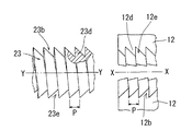
更に、該楔状の雌型係止部材12の外面は、前記テーパ穴5のテーパ面に沿った、すなわち、先端部4a側から後方にかけて外径が徐々に拡大するテーパ面12aに形成されている。更に、各雌型係止部材12の内周面には、螺旋状の係止山及び係止溝からなる係止部(雌ねじ)12bが、ケーシング3の軸芯X−Xを中心とする円弧でかつ軸芯X−Xに沿った方向に刻設されている。この螺旋状の係止部12bとして、例えば図6に示すような、螺旋状で、かつ、不等辺三角形状の係止山12d及び係止溝12eからなる係止部(雌ねじ)12bを用いることができる。
Further, the outer surface of the wedge-shaped
なお、以下において、雌型係止部材12を楔ナット12ともいう。
上記により、1個若しくは複数個の楔ナット12により係止穴(雌ねじ穴)12cが形成され、各楔ナット12がテーパ面に沿って後退することにより、その雌ねじ穴12cが拡径され、先方へ移動することにより、その雌ねじ穴12cが縮径するようになっている。
Hereinafter, the
As described above, one or a plurality of
また、前記楔ナット12の後端には、各楔ナット12に共通して係合する付勢手段受け(バネ受け)13が配置されている。
Further, an urging means receiver (spring receiver) 13 that engages with each
前記ケーシング3の後部の雌ねじ3aには、中心部にねじ穴14aを形成した蓋板14が螺着されている。前記付勢手段収納部6内の前記付勢手段受け13と蓋板14の間には付勢手段16が収納されている。該付勢手段16は、コイルバネ、ゴム、樹脂、ウレタンなどの弾性部材で形成される。本実施例1ではコイルバネを使用して圧縮状態で収納されている。該付勢手段16の付勢力により各楔ナット12は、常時先端部4a方向へ付勢されている。
A
前記蓋体14には、蓋体14から後方向に突出するアンカーバー18が螺着して固設されている。アンカーバー18の後側には、抜け止め部18aが外周側へ突出して設けられている。
An
前記の雌型連結部材1は、一方の連結部品、例えば、図3に示すようなシールドセグメント19に、ケーシング3の先端部側4a面がシールドセグメント19の接合面19aと面一になるように埋設して固設されている。
The
なお、雌型連結部材1は、雄型連結部材2が挿入できればよく、前記のように、ケーシング3の先端部4aとシールドセグメント19の接合面19aとが面一である必要はない。
The
次に、雄型連結部材2について説明する。
雄型連結部材2は、変形できる部材、例えば、発泡スチロール、ゴム等の弾性材、樹脂、ダンボールで形成された円筒状の調整部材21内に、内周に雌ねじ22aを刻設した連結体22を設け、該連結体22の先部に雄型係止部材23が、その基部側に形成した雄ねじ体23aを螺着して構成されている。
Next, the
The
前記雄型係止部材23は、前記連結体22の先端より突出しており、その先部(前側)には、先部が縮径するドーム状の案内部24が形成されている。すなわち、前記雌型係止部材12を誘導する曲面が形成され、その後部、かつ、雄ねじ体23aより先部には、螺旋状の係止山及び係止溝からなる係止部(雄ねじ)23bが刻設されている。この螺旋状の係止部23bとして、例えば図6に示すような、螺旋状で、かつ、不等辺三角形状の係止山23d及び係止溝23eからなる係止部(雄ねじ)23bを用いることができる。前記係止部(雄ねじ)23bの直径は、前記各楔ナット12が最前進した場合に、これらで形成されるねじ穴12cの直径よりも若干大径に設定されている。雄ねじ23bと雄ねじ体23aとの間には、円筒状の円筒部23cが形成され、該円筒部23cの外径は、前記抜止部材7の爪部7cの通常形態時(無加圧状態時)における先端で形成される仮想円7dの径L1よりも大径に設定されている。
The
前記連結体22の後部には、図2に示すように、アンカーバー30が螺着して固設されている。該アンカーバー30の後端には抜け止め部30aが設けられている。また、アンカーバー30の外周には、ゴム等の弾性材もしくは金属からなる空間保持用のパイプ31が設けられている。空間保持用のパイプ31の前側端部は、調整部材21の後側の係止部21aに係止し、後側端部は、アンカーバー30の抜け止め部30aに設けられたゴム等の弾性材からなる座部材32に係止している。アンカーバー30と空間保持用のパイプ31との間には空隙33が設けられている。
As shown in FIG. 2, an
なお、空隙33を設けることなく、アンカーバー30の外面に沿ってゴム等の弾性材により形成して調整部材21としても良い。
The adjusting
前記調整部材21、アンカーバー30、空間保持用パイプ31は、他方の連結部材、例えば、シールドセグメント35に、連結体22の前端面22bがシールドセグメント35の接合面35aと面一になるように埋設して固設されるもので、その前記調整部材21、空隙保持用パイプ31、抜け止め部30aの外部にはコンクリート35bが打設されている。
The
なお、雄型連結部材2は、その円筒部23cがシールドセグメント35の接合面35aより突出すればよく、前記のように連結体22の前端面22bがシールドセグメント35の接合面35aと面一である必要はない。
The
また、前記一方のシールドセグメント19における接合面19aには、図示しないシール材が突出して設けられ、他方のシールドセグメント35における接合面35aには、図示しないシール材が突出して設けられている。
Further, a sealing material (not shown) projects from the
他方の連結部材35に設けられた雄型連結部材2は、変形できる部材からなる調整部材21と空隙33と空隙保持用パイプ31と座部材32の相互作用により、アンカーバー30の抜け止め部30aを中心として雄型係止部材2はその軸芯Y−Yと直交する方向に変位できるようになっている。
The
前記楔ナット12の係止部(雌ねじ)12bと、雄型係止部材23の係止部(雄ねじ)23bとして、二等辺三角形状の係止山が連続してなる係止部や、例えば、特開2006−144956号公報に記載のような不等辺三角形状の係止山が連続してなる係止部を用いることができるが、不等辺三角形状の係止山が連続してなる係止部を用いることが好ましく、その一例を図6に示す。
As the locking part (female screw) 12b of the
次に、前記楔ナット12の雌ねじ12bと、前記雄型係止部材23の雄ねじ23bの係止山間の間隔(ねじピッチ)Pについて説明する。
Next, the interval (screw pitch) P between the locking threads of the
前記楔ナット12の雌ねじ12bと、前記雄型係止部材23の雄ねじ23bのねじピッチPは所望に形成するもので、JISに規定する細目ねじの呼び径に対するねじピッチとしてもよく、また、JISに規定する細目ねじの呼び径に対するねじピッチよりも小さくしてもよい。
The thread pitch P of the
例として、呼び径がM24(mm)の場合には、前記JIS B 0207のメートル細目ねじではねじピッチを2mm又は1.5mm又は1mmに形成するが、本発明では、ねじピッチPを0.3mm〜0.8mm、望ましくは0.5mmに設定する。 As an example, when the nominal diameter is M24 (mm), the thread pitch is 2 mm, 1.5 mm or 1 mm in the JIS B 0207 metric fine thread, but in the present invention, the thread pitch P is 0.3 mm. It is set to ˜0.8 mm, preferably 0.5 mm.
また、呼び径がM30(mm)の場合もねじピッチPを0.3mm〜0.8mm、望ましくは0.5mmに設定する。 Further, when the nominal diameter is M30 (mm), the screw pitch P is set to 0.3 mm to 0.8 mm, preferably 0.5 mm.
次に本発明をシールドセグメントに適用した例に基づいて連結操作を説明する。
先ず、雌型連結部材1の軸芯X−Xと雄型連結部材2の雄型係止部材23の軸芯Y−Yとが略同軸上に位置した状態で、一方のシールドセグメント19と他方のシールドセグメント35を相対的に近接させ、雄型係止部材23を雌型係止部材1の挿入口4bより挿入する。
Next, a connection operation will be described based on an example in which the present invention is applied to a shield segment.
First, in a state where the axis XX of the female connecting
雄型係止部材23が、雌型連結部材1における挿入口4bから進入すると、抜止部材7の爪部7cを奥部へ押し広げながら進入し、その後、雄型係止部材23が各楔ナット12を付勢手段16の付勢力に抗して後退させて各楔ナット12で形成されるねじ穴12cを拡径し、各楔ナット12の係止山を乗り越えつつ挿入する。
When the
雌型連結部材1におけるケーシング3の先端面、すなわち、一方のシールドセグメント19の接合面19aと、雄型連結部材2における連結体22の先端面、すなわち他方のシールドセグメント35の接合面35aが接して雄型連結部材2の挿入が停止されると、各楔ナット12は、付勢手段16の付勢力によって先端面4a側へ押戻されるとともにテーパ面12aによって各楔ナット12で形成される雌ねじ穴12cの径が縮径し、各楔ナット12の雌ねじ12bが雄型係止部材23の雄ねじ23bに噛合する。この時、雄型係止部材23の円筒部23cの外周面に抜止部材7の爪部7cの先端が、その復元力によって圧接する。これによって両シールドセグメント19、35は相互に連結される。
The front end surface of the
本実施例1の連結具を構成する雌型連結部材1及び雄型連結部材2は、前記のような構造を有しているため、次のような作用、効果を奏する。
Since the
従来の雄型連結部材110及び雌型連結部材107を用いて連結するシールドセグメントにおいては、図13(a)の特性Aに示すように、雄型連結部材110及び雌型連結部材107の連結時における引張り方向の荷重(引張荷重)が大きくなるほど、シールドセグメント110、111間の目開き量が大きくなるが、本実施例1の連結具を用いて連結した場合においては、図13(b)の特性Bにおける特性C示すように、引張荷重が抜止部材7の耐引張荷重より少ない間は、抜止部材7により雄型係止部材23の抜け方向の移動が抑制されて、シールドセグメント19、35の接合面19a、35a間の目開き量を、従来の雄型連結部材108及び雌型連結部材107間の目開き量よりも低く抑えることができる。
In the shield segment connected using the conventional
例えば、本発明の連結具(雌型連結部材1と雄型連結部材2)を、シールドセグメント間の連結に適用し、抜止部材7の耐引張荷重を、トンネルの施工時における、台形のシールドセグメント205と後段の連結リング202との間に加わる引張荷重よりも大きく設定した場合に、抜止部材7により雄型連結部材2、すなわち台形のシールドセグメント205の前(進行)方向Aへの移動を抑制し、台形のシールドセグメント205と後段の連結リング202との段差を、前記従来の連結具(雄型連結部材108及び雌型連結部材107)を用いて連結した場合よりも低く抑えることができ、従来技術のような大きな段差Dが殆ど生じず、次の段の連結リングを構成するシールドセグメント207との間の段差も小さくなり、シールドセグメント207を容易に連結することができる。
For example, the coupling tool (
なお、前記のように摺動案内突条11を設けた場合には、雌型連結部材1又は雄型連結部材2のいずれかを回転することにより、これらを分離できるが、このような分離が不要或いは不可にする場合には摺動案内突条11を設けない。
In addition, when the sliding
前記実施例1においては、雄型係止部材23の係止部23b及び雌型係止部材12の係止部12bを螺旋状の係止山及び係止溝で形成したが、雄型係止部材の係止部及び雌型係止部材の係止部を、軸心Y−Yに対して直交、かつ、平行な環状に形成された係止山及び係止溝を軸心方向に連続させて形成したものとしてもよい。
In the first embodiment, the locking
この環状の係止部として、例えば、図7に示すような、軸心X−Xに対して直交し、かつ、平行な環状で、かつ、不等辺三角形状の係止山37c、38cを軸心方向に連続して形成した係止部37b、38bとする雄型係止部材37と雌型係止部材28を用いることができる。
As this annular locking portion, for example, as shown in FIG. 7, locking
なお、雄型係止部材37の係止部37b及び雌型係止部材38の係止部38bの係止山及び係止溝は、図7に示すような、不等辺三角形状に限定されるものではなく、二等辺三角形状の係止山が連続してなる係止部や、例えば、特開2006−144956号公報に記載のような不等辺三角形状の係止山が連続してなる係止部を用いることができるが、不等辺三角形状の係止山が連続してなる係止部を用いることが好ましい。
In addition, the engaging crest and the engaging groove of the engaging
本実施例2においても、係止山間の間隔(ピッチ)Pの寸法は、前記実施例1に示したねじピッチの寸法に相当する値に設定する。 Also in the second embodiment, the dimension of the pitch (pitch) P between the locking ridges is set to a value corresponding to the thread pitch dimension shown in the first embodiment.
その他の部材及び構造については、前記実施例1と同様の部材及び構造を有するため、前記と同一部には前記と同一符号を付してその説明を省略する。 Since other members and structures have the same members and structures as those of the first embodiment, the same parts as those described above are denoted by the same reference numerals as those described above, and the description thereof is omitted.
また、本実施例2においても、前記実施例1と同様の作用、効果を奏する。 Also in the second embodiment, the same operations and effects as in the first embodiment are achieved.
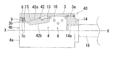
図8、図9は、実施例3を示す。
前記実施例1、2においては、雌型係止部材12の係止部12bとして、螺旋状又は環状の係止山及び係止溝からなる係止部12bを用い、雄型係止部材23の係止部23bとして、螺旋状又は環状の係止山及び係止溝からなる係止部23bを用いたが、本実施例3のようなテーパ状の係止部42b、44aを用いてもよい。
8 and 9 show a third embodiment.
In the first and second embodiments, as the locking
雌型連結部材40の雌型係止部材42の外面は、図8に示すように、前記実施例1の雌型係止部材12と同様に、テーパ穴5のテーパ面に沿った、すなわち、先端部4a側から後方にかけて外径が徐々に拡大する外側テーパ面42aで形成されている。
As shown in FIG. 8, the outer surface of the
また、雌型連結部材42の内周面には、先端部4a側から後方にかけて内径が徐々に拡大する内側テーパ面からなる係止部42bが、ケーシング2の軸心X−Xを中心とする円弧で形成されている。また、係止部42bは、軸心X−X方向において傾斜した直線で形成され、かつ、軸心X−Xに対する傾斜角は、外側テーパ面42aのものよりも小さく設定されている。
Further, on the inner peripheral surface of the female connecting
雄型連結部材41の雄型係止部材44の係止部44aは、図9に示すように、前記実施例1の雄型係止部材23の係止部23bと同様に、案内部24と円筒部23cとの間に位置し、かつ、後方が縮径する円筒状面からなる。
As shown in FIG. 9, the locking portion 44a of the
係止部44aの軸心Y−Yに対する傾斜角は、前記雌型連結部材42の係止部42bの軸心X−Xに対する傾斜角と略同一に設定されている。
The inclination angle of the locking portion 44a with respect to the axis YY is set substantially the same as the inclination angle of the locking
その他の部材及び構造については、前記実施例1と同様の部材及び構造を有するため、前記と同一部には前記と同一符号を付してその説明を省略する。 Since other members and structures have the same members and structures as those of the first embodiment, the same parts as those described above are denoted by the same reference numerals as those described above, and the description thereof is omitted.
また、本実施例3においても、前記実施例1と同様の作用、効果を奏する。 Also in the third embodiment, the same operations and effects as the first embodiment are achieved.
1 雌型連結部材
2 雄型連結部材
3 ケーシング
4 収納室
7 抜止部材
7c 爪部
12、38、42 雌型係止部材
12b、38b 雌型係止部材の係止部
16 付勢手段
23、37、44 雄型連結部材
23b、37b、44a 雄型連結部材の係止部
19、35 シールドセグメント
DESCRIPTION OF
Claims (8)
前記雌型連結部材の内部に先端部が開口する収納室を形成し、該収納室に、前記雄型係止部材を挿入することにより、該雄型係止部材を係止する雌型係止部材を設け、
前記収納室内に、前記雄型係止部材と前記雌型係止部材との連結時に、前記雄型係止部材の外周面に圧接するとともに、前記雄型係止部材に抜け方向の力が作用した時に、該雄型係止部材を挿入方向に付勢して、該雄型係止部材の抜けを抑制する抜止部材を設けたことを特徴とする連結具。 Consists of a male coupling member and a female coupling member having a male locking member at the tip,
A female-type latch that forms a storage chamber with an open end inside the female-type connecting member, and that locks the male-type locking member by inserting the male-type locking member into the storage chamber. A member,
When the male locking member and the female locking member are connected to each other in the storage chamber, the male locking member is pressed against the outer peripheral surface of the male locking member, and a pulling force acts on the male locking member. when the biases of the male locking member in the insertion direction, coupling, characterized in that a suppressing stop member detachment of the male engagement member.
前記雌型連結部材の内部に先端部が開口する収納室を設け、該収納室内に、係止山及び係止溝を交互に形成してなる係止部を内面側に刻設した雌型係止部材を設けるとともに、
前記雄型連結部材の先部に、係止山及び係止谷を交互に形成してなる係止部を外面に刻設した雄型係止部材を設け、
前記雌型係止部材間に前記雄型係止部材を挿入することにより、前記雌型係止部材により構成される係止穴が拡径した後に、付勢手段により前記係止穴が縮径し前記雌型係止部材の係止部と、前記雄型係止部材の係止部とが噛合するようにした連結具であって、
前記収納室内に、前記雄型係止部材と前記雌型係止部材との連結時に、前記雄型係止部材の外周面に圧接するとともに、前記雄型係止部材に抜け方向の力が作用した時に、該雄型係止部材を挿入方向に付勢して、雄型係止部材の抜けを抑制する抜止部材を設けたことを特徴とする連結具。 It consists of a female connection member and a male connection member,
A female mold member in which a storage chamber having an opening at the tip is provided inside the female coupling member, and a locking portion formed by alternately forming a locking mountain and a locking groove on the inner surface side is provided in the storage chamber. While providing a stop member,
A male locking member having a locking portion formed by alternately forming locking peaks and locking valleys on the outer surface is provided at the tip of the male connecting member,
By inserting the male locking member between the female locking members, the locking hole constituted by the female locking member is expanded in diameter, and then the locking hole is reduced in diameter by the biasing means. And a coupling tool in which the locking portion of the female locking member and the locking portion of the male locking member are engaged with each other,
When the male locking member and the female locking member are connected to each other in the storage chamber, the male locking member is pressed against the outer peripheral surface of the male locking member, and a pulling force acts on the male locking member. And a retaining member that urges the male locking member in the insertion direction to prevent the male locking member from coming off.
前記雌型連結部材の内部に先端部が開口する収納室を設け、該収納室内に、先端側から 奥部側に向って内径が徐々に拡径する係止部を内面側に形成した雌型係止部材を設けるとともに、
前記雄型連結部材の先部に、先部から奥部に向かって縮径する係止部を外面に形成した雄型係止部材を設け、
前記雌型係止部材間に前記雄型連結部材を挿入することにより、前記雌型係止部材により構成される係止穴が拡径した後に、付勢手段により前記係止穴が縮径し前記雌型係止部材の係止部と、前記雄型係止部材の係止部とが係合するようにした連結具であって、
前記収納室内に、前記雄型係止部材と前記雌型係止部材との連結時に、前記雄型係止部材の外周面に圧接するとともに、前記雄型係止部材に抜け方向の力が作用した時に、該雄型係止部材を挿入方向に付勢して、雄型係止部材の抜けを抑制する抜止部材を設けたことを特徴とする連結具。 It consists of a female connection member and a male connection member,
A female mold in which a storage chamber having an opening at the tip is provided inside the female connecting member, and a locking portion whose inner diameter gradually increases from the tip toward the back is formed on the inner surface of the storage chamber. While providing a locking member,
At the front part of the male connecting member, a male locking member is provided with a locking part formed on the outer surface, the diameter of which decreases from the front part toward the back part.
By inserting the male coupling member between the female locking members, the locking hole constituted by the female locking member is expanded in diameter, and then the locking hole is reduced in diameter by the urging means. A coupling tool in which a locking portion of the female locking member and a locking portion of the male locking member are engaged,
When the male locking member and the female locking member are connected to each other in the storage chamber, the male locking member is pressed against the outer peripheral surface of the male locking member, and a pulling force acts on the male locking member. And a retaining member that urges the male locking member in the insertion direction to prevent the male locking member from coming off.
前記雌型連結部材の内部に先端部が開口する収納室を設け、該収納室内に、係止山及び係止谷を交互に形成してなる係止部を内面側に刻設した雌型係止部材を設けるとともに、
前記雄型連結部材の先部に、係止山及び係止溝を交互に形成してなる係止部を外面に刻設した雄型係止部材を設け、
前記雌型係止部材間に前記雄型係止部材を挿入することにより、前記雌型係止部材により構成される係止穴が拡径した後に、付勢手段により前記係止穴が縮径し前記雌型係止部材の係止部と、前記雄型係止部材の係止部とが噛合するようにし、
前記収納室内に、前記雄型係止部材と前記雌型係止部材との連結時に、前記雄型係止部材の外周面に圧接するとともに、前記雄型係止部材に抜け方向の力が作用した時に、該雄型係止部材を挿入方向に付勢して、雄型係止部材の抜けを抑制する抜止部材を設けた連結具を使用し、
前記雌型連結部材を、連結すべき一方のコンクリート部材に固設し、前記雄型連結部材を連結すべき他方のコンクリート部材に固設したことを特徴とするコンクリート部材の連結装置。 It consists of a female connection member and a male connection member,
A female engagement member in which a storage chamber having an opening at the tip is provided inside the female connection member, and a locking portion formed by alternately forming a locking peak and a locking valley is formed on the inner surface side in the storage chamber. While providing a stop member,
A male locking member having a locking portion formed by alternately forming a locking mountain and a locking groove on the outer surface is provided at the tip of the male connecting member,
By inserting the male locking member between the female locking members, the locking hole constituted by the female locking member is expanded in diameter, and then the locking hole is reduced in diameter by the biasing means. The engaging portion of the female locking member and the locking portion of the male locking member are engaged with each other,
When the male locking member and the female locking member are connected to each other in the storage chamber, the male locking member is pressed against the outer peripheral surface of the male locking member, and a pulling force acts on the male locking member. When using the connector provided with a retaining member that urges the male locking member in the insertion direction to prevent the male locking member from coming off,
A connecting device for a concrete member, wherein the female connecting member is fixed to one concrete member to be connected, and the male connecting member is fixed to the other concrete member to be connected.
前記雌型連結部材の内部に先端部が開口する収納室を設け、該収納室内に、先端側から奥部側に向って内径が徐々に拡径する係止部を内面側に形成した雌型係止部材を設けるとともに、
前記雄型連結部材の先部に、先部から奥部に向かって縮径する係止部を外面に形成した雄型係止部材を設け、
前記雌型係止部材間に前記雄型係止部材を挿入することにより、前記雌型係止部材により構成される係止穴が拡径した後に、付勢手段により前記係止穴が縮径し前記雌型係止部材の係止部と、前記雄型係止部材の係止部とが係合するようにし、
前記収納室内に、前記雄型係止部材と前記雌型係止部材との連結時に、前記雄型係止部材の外周面に圧接するとともに、前記雄型係止部材に抜け方向の力が作用した時に、該雄型係止部材を挿入方向に付勢して、雄型係止部材の抜けを抑制する抜止部材を設けた連結具を使用し、
前記雌型連結部材を、連結すべき一方のコンクリート部材に固設し、前記雄型連結部材を連結すべき他方のコンクリート部材に固設したことを特徴とするコンクリート部材の連結装置。 It consists of a female connection member and a male connection member,
A female mold in which a storage chamber having an opening at the tip is provided inside the female connecting member, and a locking portion whose inner diameter gradually increases from the tip toward the back is formed on the inner surface in the storage chamber. While providing a locking member,
At the front part of the male connecting member, a male locking member is provided with a locking part formed on the outer surface, the diameter of which decreases from the front part toward the back part.
By inserting the male locking member between the female locking members, the locking hole constituted by the female locking member is expanded in diameter, and then the locking hole is reduced in diameter by the biasing means. The engaging portion of the female locking member and the locking portion of the male locking member are engaged,
When the male locking member and the female locking member are connected to each other in the storage chamber, the male locking member is pressed against the outer peripheral surface of the male locking member, and a pulling force acts on the male locking member. When using the connector provided with a retaining member that urges the male locking member in the insertion direction to prevent the male locking member from coming off,
A connecting device for a concrete member, wherein the female connecting member is fixed to one concrete member to be connected, and the male connecting member is fixed to the other concrete member to be connected.
Priority Applications (1)
| Application Number | Priority Date | Filing Date | Title |
|---|---|---|---|
| JP2006303156A JP4814059B2 (en) | 2006-11-08 | 2006-11-08 | CONNECTING DEVICE AND CONCRETE MEMBER CONNECTING DEVICE USING THE SAME |
Applications Claiming Priority (1)
| Application Number | Priority Date | Filing Date | Title |
|---|---|---|---|
| JP2006303156A JP4814059B2 (en) | 2006-11-08 | 2006-11-08 | CONNECTING DEVICE AND CONCRETE MEMBER CONNECTING DEVICE USING THE SAME |
Publications (2)
| Publication Number | Publication Date |
|---|---|
| JP2008121199A JP2008121199A (en) | 2008-05-29 |
| JP4814059B2 true JP4814059B2 (en) | 2011-11-09 |
Family
ID=39506254
Family Applications (1)
| Application Number | Title | Priority Date | Filing Date |
|---|---|---|---|
| JP2006303156A Active JP4814059B2 (en) | 2006-11-08 | 2006-11-08 | CONNECTING DEVICE AND CONCRETE MEMBER CONNECTING DEVICE USING THE SAME |
Country Status (1)
| Country | Link |
|---|---|
| JP (1) | JP4814059B2 (en) |
Families Citing this family (4)
| Publication number | Priority date | Publication date | Assignee | Title |
|---|---|---|---|---|
| JP5908798B2 (en) * | 2012-06-08 | 2016-04-26 | 前田建設工業株式会社 | CONNECTING DEVICE AND CONCRETE MEMBER CONNECTING DEVICE USING THE SAME |
| JP5908797B2 (en) * | 2012-06-08 | 2016-04-26 | 前田建設工業株式会社 | CONNECTING DEVICE AND CONCRETE MEMBER CONNECTING DEVICE USING THE SAME |
| WO2016088168A1 (en) * | 2014-12-01 | 2016-06-09 | 株式会社湘南合成樹脂製作所 | Method for regenerating existing pipes |
| JP6762015B2 (en) * | 2017-01-06 | 2020-09-30 | 株式会社三ツ知 | Connector |
Family Cites Families (3)
| Publication number | Priority date | Publication date | Assignee | Title |
|---|---|---|---|---|
| JP2005226219A (en) * | 2003-10-10 | 2005-08-25 | Nippon Koatsu Concrete Kk | Axial direction joint of concrete segment |
| JP4469714B2 (en) * | 2004-10-18 | 2010-05-26 | 株式会社三ツ知 | Connecting device and connecting device for concrete member using the same |
| JP4654009B2 (en) * | 2004-11-22 | 2011-03-16 | 株式会社三ツ知 | CONNECTING DEVICE AND CONCRETE MEMBER CONNECTING DEVICE USING THE SAME |
-
2006
- 2006-11-08 JP JP2006303156A patent/JP4814059B2/en active Active
Also Published As
| Publication number | Publication date |
|---|---|
| JP2008121199A (en) | 2008-05-29 |
Similar Documents
| Publication | Publication Date | Title |
|---|---|---|
| JP5242569B2 (en) | Bucket tooth mounting structure and mounting pin assembly | |
| TW200838064A (en) | Joint, and socket and plug used for the joint | |
| KR20090120450A (en) | Male coupling for connecting to female threaded coupling | |
| JP4814059B2 (en) | CONNECTING DEVICE AND CONCRETE MEMBER CONNECTING DEVICE USING THE SAME | |
| JP2009092165A (en) | Connector and connection device of concrete member using the same | |
| JP4781220B2 (en) | Pipe fitting and backup ring used for it | |
| JP2020070921A (en) | Flexible tube joint and locking tool for joint | |
| JP5908797B2 (en) | CONNECTING DEVICE AND CONCRETE MEMBER CONNECTING DEVICE USING THE SAME | |
| JP6370721B2 (en) | CONNECTING DEVICE AND CONCRETE MEMBER CONNECTING DEVICE USING THE SAME | |
| JP5908798B2 (en) | CONNECTING DEVICE AND CONCRETE MEMBER CONNECTING DEVICE USING THE SAME | |
| JP2002098276A (en) | Pipe joint | |
| JP5197298B2 (en) | Connector | |
| JP5197281B2 (en) | Connector | |
| JPH11201347A (en) | Pipe joint | |
| JP2007298106A (en) | Pipe fitting | |
| JP2000145754A (en) | Ball joint | |
| JP3863170B2 (en) | Concrete member connection device | |
| JP6176954B2 (en) | Segment connection joint and segment | |
| JP5725564B2 (en) | Connecting joints and segments | |
| JP4150414B1 (en) | Anchor bolt and method for manufacturing anchor bolt | |
| JP4757605B2 (en) | Concrete member connector | |
| JP2000227187A (en) | Fall-out preventing member | |
| JP4654009B2 (en) | CONNECTING DEVICE AND CONCRETE MEMBER CONNECTING DEVICE USING THE SAME | |
| JP6762015B2 (en) | Connector | |
| JP4975475B2 (en) | Segment fitting |
Legal Events
| Date | Code | Title | Description |
|---|---|---|---|
| A621 | Written request for application examination |
Free format text: JAPANESE INTERMEDIATE CODE: A621 Effective date: 20090805 |
|
| A977 | Report on retrieval |
Free format text: JAPANESE INTERMEDIATE CODE: A971007 Effective date: 20110124 |
|
| A131 | Notification of reasons for refusal |
Free format text: JAPANESE INTERMEDIATE CODE: A131 Effective date: 20110201 |
|
| A521 | Written amendment |
Free format text: JAPANESE INTERMEDIATE CODE: A523 Effective date: 20110315 |
|
| TRDD | Decision of grant or rejection written | ||
| A01 | Written decision to grant a patent or to grant a registration (utility model) |
Free format text: JAPANESE INTERMEDIATE CODE: A01 Effective date: 20110802 |
|
| A01 | Written decision to grant a patent or to grant a registration (utility model) |
Free format text: JAPANESE INTERMEDIATE CODE: A01 |
|
| A61 | First payment of annual fees (during grant procedure) |
Free format text: JAPANESE INTERMEDIATE CODE: A61 Effective date: 20110825 |
|
| R150 | Certificate of patent or registration of utility model |
Free format text: JAPANESE INTERMEDIATE CODE: R150 |
|
| FPAY | Renewal fee payment (event date is renewal date of database) |
Free format text: PAYMENT UNTIL: 20270902 Year of fee payment: 16 |
|
| S531 | Written request for registration of change of domicile |
Free format text: JAPANESE INTERMEDIATE CODE: R313531 |
|
| R350 | Written notification of registration of transfer |
Free format text: JAPANESE INTERMEDIATE CODE: R350 |