JP4813630B2 - Endoscope device - Google Patents
Endoscope device Download PDFInfo
- Publication number
- JP4813630B2 JP4813630B2 JP2011524035A JP2011524035A JP4813630B2 JP 4813630 B2 JP4813630 B2 JP 4813630B2 JP 2011524035 A JP2011524035 A JP 2011524035A JP 2011524035 A JP2011524035 A JP 2011524035A JP 4813630 B2 JP4813630 B2 JP 4813630B2
- Authority
- JP
- Japan
- Prior art keywords
- treatment instrument
- distal
- treatment
- endoscope
- peripheral surface
- Prior art date
- Legal status (The legal status is an assumption and is not a legal conclusion. Google has not performed a legal analysis and makes no representation as to the accuracy of the status listed.)
- Active
Links
Images


Classifications
-
- A—HUMAN NECESSITIES
- A61—MEDICAL OR VETERINARY SCIENCE; HYGIENE
- A61B—DIAGNOSIS; SURGERY; IDENTIFICATION
- A61B1/00—Instruments for performing medical examinations of the interior of cavities or tubes of the body by visual or photographical inspection, e.g. endoscopes; Illuminating arrangements therefor
- A61B1/012—Instruments for performing medical examinations of the interior of cavities or tubes of the body by visual or photographical inspection, e.g. endoscopes; Illuminating arrangements therefor characterised by internal passages or accessories therefor
- A61B1/018—Instruments for performing medical examinations of the interior of cavities or tubes of the body by visual or photographical inspection, e.g. endoscopes; Illuminating arrangements therefor characterised by internal passages or accessories therefor for receiving instruments
-
- A—HUMAN NECESSITIES
- A61—MEDICAL OR VETERINARY SCIENCE; HYGIENE
- A61B—DIAGNOSIS; SURGERY; IDENTIFICATION
- A61B17/00—Surgical instruments, devices or methods, e.g. tourniquets
- A61B17/28—Surgical forceps
- A61B17/29—Forceps for use in minimally invasive surgery
-
- A—HUMAN NECESSITIES
- A61—MEDICAL OR VETERINARY SCIENCE; HYGIENE
- A61B—DIAGNOSIS; SURGERY; IDENTIFICATION
- A61B17/00—Surgical instruments, devices or methods, e.g. tourniquets
- A61B17/00234—Surgical instruments, devices or methods, e.g. tourniquets for minimally invasive surgery
- A61B2017/00292—Surgical instruments, devices or methods, e.g. tourniquets for minimally invasive surgery mounted on or guided by flexible, e.g. catheter-like, means
- A61B2017/00296—Surgical instruments, devices or methods, e.g. tourniquets for minimally invasive surgery mounted on or guided by flexible, e.g. catheter-like, means mounted on an endoscope
-
- A—HUMAN NECESSITIES
- A61—MEDICAL OR VETERINARY SCIENCE; HYGIENE
- A61B—DIAGNOSIS; SURGERY; IDENTIFICATION
- A61B17/00—Surgical instruments, devices or methods, e.g. tourniquets
- A61B17/28—Surgical forceps
- A61B17/29—Forceps for use in minimally invasive surgery
- A61B2017/2926—Details of heads or jaws
- A61B2017/2927—Details of heads or jaws the angular position of the head being adjustable with respect to the shaft
- A61B2017/2929—Details of heads or jaws the angular position of the head being adjustable with respect to the shaft with a head rotatable about the longitudinal axis of the shaft
- A61B2017/293—Details of heads or jaws the angular position of the head being adjustable with respect to the shaft with a head rotatable about the longitudinal axis of the shaft with means preventing relative rotation between the shaft and the actuating rod
Description
本発明は、内視鏡と、内視鏡又は内視鏡とは別体の管状体に設けられる処置具挿通路に挿通されるマニピュレータ、鉗子等の処置具とを備える内視鏡装置に関する。 The present invention relates to an endoscope apparatus including an endoscope and a treatment tool such as a manipulator or a forceps inserted through a treatment tool insertion path provided in a tubular body separate from the endoscope or the endoscope.
一般に、内視鏡を体腔内に挿入し、内視鏡又は内視鏡とは別体の管状体の処置挿通路を介して内視鏡又は管状体の先端からマニピュレータ、鉗子等の処置具を突出させる内視鏡装置が用いられている。内視鏡装置では、内視鏡の観察下で、処置具が体腔内で処置を行う。 In general, an endoscope is inserted into a body cavity, and a treatment tool such as a manipulator or forceps is inserted from the endoscope or the distal end of the tubular body via a treatment insertion path of the tubular body separate from the endoscope or the endoscope. Endoscopic endoscope devices are used. In an endoscope apparatus, a treatment tool performs treatment in a body cavity under observation of an endoscope.
内視鏡又は管状体の処置具挿通路に挿通される処置具として、特許文献1には、患部を高周波電極で把持して処置を行う高周波処置具が開示されている。この高周波処置具は、体腔内に挿入される挿入部と、挿入部より基端方向側に設けられる操作部とを備える。挿入部は、高周波電極が設けられる先端処置部と、先端処置部より基端方向側に設けられ、長手方向に延設される処置具本体とを備える。先端処置部の回転動作を行う際には、操作部での回転操作による回転トルクが処置具本体の内部に挿通される回転操作伝達部材である導電線を介して先端処置部に伝達され、先端処置部が処置具本体に対して軸回り方向に回転する。 As a treatment tool inserted through a treatment instrument insertion passage of an endoscope or a tubular body, Patent Document 1 discloses a high-frequency treatment instrument that performs treatment by grasping an affected area with a high-frequency electrode. This high-frequency treatment instrument includes an insertion portion that is inserted into a body cavity, and an operation portion that is provided on the proximal direction side of the insertion portion. The insertion section includes a distal treatment section where a high-frequency electrode is provided, and a treatment instrument body which is provided proximally from the distal treatment section and extends in the longitudinal direction. When performing the rotational operation of the distal treatment section, the rotational torque due to the rotational operation at the operation section is transmitted to the distal treatment section via a conductive wire that is a rotational operation transmission member inserted into the treatment instrument body, The treatment portion rotates around the axis with respect to the treatment instrument body.
また、先端処置部と処置具本体との間にモータを設けた処置具もある。この処置具では、モータを駆動することにより先端処置部が処置具本体に対して軸回り方向に回転動作を行う。すなわち、モータにより、先端処置部を処置具本体に対して回転させる回転関節部が構成されている。 There is also a treatment instrument in which a motor is provided between the distal treatment section and the treatment instrument body. In this treatment instrument, by driving the motor, the distal treatment section rotates around the axis relative to the treatment instrument body. That is, a rotary joint portion that rotates the distal treatment portion relative to the treatment instrument main body is configured by the motor.
さらに、先端処置部と処置具本体との間に傘歯車を設け、傘歯車を回転させることにより先端処置部が回転動作を行う処置具もある。この処置具では、傘歯車に処置具本体の内部に挿通されるワイヤ等の回転操作伝達部材が接続されている。ワイヤの引張り動作及び押出し動作を行うことにより、傘歯車が回転し、先端処置部が可撓管部に対して軸回り方向に回転する。すなわち、傘歯車により、先端処置部を処置具本体に対して回転させる回転関節部が構成されている。 Further, there is a treatment instrument in which a bevel gear is provided between the distal treatment section and the treatment instrument body and the distal treatment section rotates by rotating the bevel gear. In this treatment tool, a rotation operation transmission member such as a wire inserted into the treatment tool main body is connected to the bevel gear. By performing the wire pulling operation and the pushing operation, the bevel gear rotates, and the distal treatment section rotates in the direction around the axis with respect to the flexible tube section. That is, the rotating joint part which rotates a front-end | tip treatment part with respect to a treatment tool main body by the bevel gear wheel is comprised.
上記特許文献1の高周波処置具では、操作部での回転トルクを伝達する導電線が長手方向に延設される構成であるため、導電線の基端側での回転トルクが先端処置部に適切に伝達されない場合がある。この場合、先端処置部の回転追従性が低下してしまい、操作部での回転量と先端処置部での回転力が異なったり、先端処置部の回転動作にムラが発生したりする。 In the high frequency treatment tool of the above-mentioned patent document 1, since the conductive wire for transmitting the rotational torque at the operation portion is configured to extend in the longitudinal direction, the rotational torque on the proximal end side of the conductive wire is appropriate for the distal treatment portion. May not be transmitted. In this case, the rotational followability of the distal treatment section is deteriorated, the amount of rotation in the operation section and the rotational force in the distal treatment section are different, or unevenness occurs in the rotational operation of the distal treatment section.
先端処置部と処置具本体との間にモータ、傘歯車等により構成される回転関節部を設けた処置具では、先端処置部の回転追従性が低下する問題は生じない。しかし、この処置具では、例えば先端処置部に設けられる把持部で組織等を把持した際に、回転関節部より先端方向側に設けられる把持部に力が掛かってしまう。この状態で先端処置部の回転操作を行った場合、回転関節部より先端法向側の先端処置部が回転せず、回転関節部より基端方向側の部分が回転操作による回転方向とは反対方向に回転することがある。すなわち、先端処置部に力が掛かった際に、回転操作が先端処置部に適切に伝達されないことがある。 In a treatment instrument in which a rotary joint part constituted by a motor, a bevel gear or the like is provided between the distal treatment part and the treatment tool main body, there is no problem that the rotational followability of the distal treatment part is lowered. However, in this treatment instrument, for example, when a tissue or the like is grasped by a grasping portion provided in the distal treatment portion, a force is applied to the grasping portion provided on the distal direction side from the rotary joint portion. In this state, when the rotation operation of the distal treatment section is performed, the distal treatment section on the distal direction side from the rotation joint section does not rotate, and the proximal side portion from the rotation joint section is opposite to the rotation direction by the rotation operation. May rotate in the direction. That is, when a force is applied to the distal treatment section, the rotation operation may not be properly transmitted to the distal treatment section.
本発明は上記課題に着目してなされたものであり、その目的とするところは、処置具の先端処置部に力が掛かった際にも、先端処置部に回転操作が適切に伝達される内視鏡装置を提供することある。 The present invention has been made paying attention to the above-mentioned problems, and the object of the present invention is that the rotation operation is appropriately transmitted to the distal treatment section even when a force is applied to the distal treatment section of the treatment instrument. An endoscopic device may be provided.
上記目的を達成するため、本発明のある態様では、内視鏡と、長手方向に延設される処置具本体と、前記処置具本体より先端方向側に設けられる先端処置部と、前記処置具本体と前記先端処置部との間に設けられ、前記先端処置部を前記処置具本体に対して軸回り方向に回転させる回転関節部とを備える処置具と、前記内視鏡又は前記内視鏡とは別体の管状体に設けられ、前記処置具が挿通される処置具挿通路を規定する内周面部と、前記処置具本体が前記内視鏡に対して軸回り方向に回転する際に、前記内周面部の先端方向側の部位と前記処置具本体の先端方向側の部位の外周面との接触部に摩擦力を付与する摩擦力付与部と、を備える内視鏡装置を提供する。 In order to achieve the above object, in one aspect of the present invention, an endoscope, a treatment instrument body extending in a longitudinal direction, a distal treatment section provided on a distal direction side of the treatment instrument body, and the treatment instrument A treatment instrument comprising a rotary joint provided between a main body and the distal treatment section and rotating the distal treatment section in a direction around an axis with respect to the treatment instrument body; and the endoscope or the endoscope And an inner peripheral surface portion that defines a treatment instrument insertion passage through which the treatment instrument is inserted, and the treatment instrument main body rotates about the axis with respect to the endoscope. An endoscope apparatus comprising: a frictional force applying unit that applies a frictional force to a contact portion between a distal end side portion of the inner peripheral surface portion and an outer peripheral surface of a distal end side portion of the treatment instrument body. .
この内視鏡装置では、前記摩擦力付与部は、前記内周面部の前記先端方向側の部位、及び、前記処置具本体の前記先端方向側の部位の前記外周面の少なくともいずれか一方に設けられていることが好ましい。また、前記摩擦力付与部は、前記内周面部の前記先端方向側の部位から内周側に向けて突出する凸部を備えることが好ましい。また、前記摩擦力付与部は、前記処置具本体の前記先端方向側の部位の前記外周面から外周側に向けて突出する凸部を備えることも好ましい。さらに、前記摩擦力付与部は、前記処置具本体の前記先端方向側の部位の前記外周面に設けられる膨張可能なバルーンを備えることが好ましい。 In this endoscope apparatus, the frictional force applying portion is provided on at least one of the distal end side portion of the inner peripheral surface portion and the outer peripheral surface of the distal end side portion of the treatment instrument body. It is preferable that Moreover, it is preferable that the said frictional force provision part is provided with the convex part which protrudes toward the inner peripheral side from the site | part of the said front end direction side of the said inner peripheral surface part. Moreover, it is preferable that the said frictional force provision part is provided with the convex part which protrudes toward the outer peripheral side from the said outer peripheral surface of the site | part of the said treatment tool main body at the said front end direction side. Furthermore, it is preferable that the said frictional force provision part is provided with the inflatable balloon provided in the said outer peripheral surface of the site | part of the said treatment tool main body at the said front end direction side.
本発明によれば、処置具の先端処置部に力が掛かった際にも、先端処置部に回転操作が適切に伝達される内視鏡装置を提供することができる。 According to the present invention, it is possible to provide an endoscope apparatus in which a rotation operation is appropriately transmitted to the distal treatment section even when a force is applied to the distal treatment section of the treatment instrument.
(第1の実施形態)
本発明の第1の実施形態について図1乃至図4を参照して説明する。(First embodiment)
A first embodiment of the present invention will be described with reference to FIGS.
図1及び図2は、本実施形態の内視鏡装置1を示す図である。図1に示すように、内視鏡装置1は、患部等の被写体を撮像する内視鏡2を備える。内視鏡2は、体腔内に挿入される内視鏡挿入部4と、内視鏡挿入部4より基端方向側に設けられる内視鏡操作部6とを備える。内視鏡操作部6には、ユニバーサルコード8の一端が接続されている。ユニバーサルコード8の他端は、スコープコネクタ9を介して画像観察装置、照明電源装置(いずれも図示しない)等に接続されている。
FIG.1 and FIG.2 is a figure which shows the endoscope apparatus 1 of this embodiment. As shown in FIG. 1, the endoscope apparatus 1 includes an
内視鏡挿入部4は、硬質の先端硬性部10と、先端硬性部10より基端方向側に設けられ、湾曲作動される内視鏡湾曲部12と、内視鏡湾曲部12より基端方向側に設けられ、長尺で可撓性を有する内視鏡可撓管部14とを備える。
The endoscope insertion portion 4 includes a hard distal
図2に示すように、内視鏡2の内視鏡操作部6には、処置具挿入口16が配設されている。処置具挿入口16から内周面部17が、内視鏡可撓管部14及び内視鏡湾曲部12を通って、先端硬性部10まで延設されている。内周面部17により、処置具挿通路18が規定されている。先端硬性部10の先端面には、処置具挿通路18の先端となる処置具用口19が設けられている。
As shown in FIG. 2, a treatment
内視鏡2の処置具挿通路18には、処置具20が長手方向に進退自在に挿通されている。処置具20は、体腔内に挿入される処置具挿入部22と、処置具挿入部22より基端方向側に設けられる処置具操作部23とを備える。処置具挿入部22は、長手方向に延設され、可撓性を有する処置具本体24と、処置具本体24より先端方向側に設けられ、処置を行う先端処置部26とを備える。処置具本体24と先端処置部26との間には、回転関節部27が設けられている。回転関節部27が作動することにより、先端処置部26が処置具本体24に対して軸回り方向に回転する。また、先端処置部26には、組織等を把持する把持部28が設けられている。
A
図2に示すように、回転関節部27には、モータ31が設けられている。モータ31は、電気配線32を介して、処置具操作部23に設けられる入力部33に接続されている。入力部33での回転操作により、モータ31が駆動し、回転関節部27が作動する。回転関節部27が作動することにより、先端処置部26が処置具本体24に対して軸回り方向に回転する。なお、入力部33には、ワイヤ等の把持操作伝達部材(図示しない)が接続されている。入力部33での把持操作は、把持操作伝達部材を介して、把持部28に伝達される。これにより、把持部28が組織等を把持する把持動作を行う。
As shown in FIG. 2, the
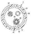
図3は内視鏡装置1の先端方向側の部位の構成を示す図であり、図4は図3のIV−IV線断面図である。図3に示すように、内視鏡2の先端硬性部10の先端面には、観察窓35及び照明窓36が設けられている。先端硬性部10に設けられる撮像素子(図示しない)は、観察窓35を介して、被写体の撮像を行う。撮像素子には、撮像ケーブル37(図4参照)が接続されている。撮像ケーブル37は、内視鏡挿入部4、内視鏡操作部6及びユニバーサルコード8の内部を通って、画像観察装置(図示しない)に接続されている。撮像素子により撮像された被写体像は、撮像ケーブル37を介して、画像観察装置に出力される。照明窓36には、ライトガイド38(図4参照)が光学的に接続されている。ライトガイド38は、内視鏡挿入部4、内視鏡操作部6及びユニバーサルコード8の内部を通って、照明電源装置(図示しない)に光学的に接続されている。照明電源装置からの出射光は、ライトガイド38により導光され、照明窓36を介して被写体を照射している。
FIG. 3 is a diagram showing a configuration of a portion on the distal direction side of the endoscope apparatus 1, and FIG. 4 is a sectional view taken along line IV-IV in FIG. As shown in FIG. 3, an observation window 35 and an illumination window 36 are provided on the distal end surface of the distal end
また、処置具20が処置具挿通路18に挿通される状態では、先端硬性部10の先端面の処置具用口19から処置具20が先端方向に突出している。先端処置部26の外周面には第1の指標39Aが、処置具本体24の外周面に複数の第2の指標39Bが設けられている。これにより、術者は、内視鏡2の撮像素子により撮像された画像から、第1の指標39Aと第2の指標39Bとの位置関係を確認する。そして、第1の指標39Aと第2の指標39Bとの位置関係から、先端処置部26の中立位置(初期位置)及び先端処置部26の処置具本体24に対する軸回り方向への中立位置からの回転量を認識可能となっている。したがって、入力部33での回転操作が適切に伝達されているか、認識可能となっている。
Further, in a state where the
図4に示すように、内視鏡2の内周面部17の先端方向側の部位には、内周側に向けて突出する複数の凸部41が、処置具挿通路18の周方向に並設されている。凸部41は、長手方向に所定の長さを有して設けられている。処置具挿通路18に処置具20が挿通された状態では、それぞれの凸部41は処置具本体24の外周面と接触している。このような構成にすることにより、処置具本体24が内視鏡2に対して軸回り方向に回転する際に、凸部41と処置具本体24の先端方向側の部位の外周面との接触部で、処置具本体24の回転方向とは反対方向に摩擦力が付与される。すなわち、凸部41が、凸部41(内周面部17の先端方向側の部位)と処置具本体24の先端方向側の部位の外周面との接触部に摩擦力を付与する摩擦力付与部となっている。凸部41によって付与される摩擦力により、処置具本体24の先端方向側の部位の軸回り方向への回転が規制されている。なお、凸部41により、処置具20の内視鏡2に対する長手方向への進退動作は規制されない。
As shown in FIG. 4, a plurality of
次に、本実施形態に係る内視鏡装置1の作用について説明する。内視鏡装置1では、内視鏡2の処置具挿通路18に処置具20を挿通して処置が行われる。内視鏡装置1の処置では、先端処置部26の把持部28で組織等を把持することがある。把持部28で把持動作を行う際には、回転関節部27より先端方向側に設けられる把持部28に力が掛かってしまう。この状態で回転関節部27を作動して先端処置部26の回転操作を行った場合、回転関節部27より基端方向側に設けられる処置具本体24の先端方向側の部位が、回転操作による回転方向とは反対方向に回転しようとする。
Next, the operation of the endoscope apparatus 1 according to this embodiment will be described. In the endoscope apparatus 1, the
内視鏡装置1では、処置具挿通路18に処置具20が挿通された際に、それぞれの凸部41が処置具本体24の外周面と接触している。このため、処置具本体24が内視鏡2に対して軸回り方向に回転する際に、凸部41(内周面部17の先端方向側の部位)と処置具本体24の先端方向側の部位の外周面との接触部で、処置具本体24の回転方向とは反対方向に摩擦力が付与される。凸部41により付与される摩擦力により、処置具本体24の先端方向側の部位の回転操作による回転方向とは反対方向への回転が規制されている。回転関節部27より基端方向側に設けられる処置具本体24の先端方向側の部位の軸回り方向への回転が規制されることにより、把持部28により組織等を把持した状態(先端処置部26に力が掛かった状態)でも、回転操作が回転関節部27より先端方向側の先端処置部26に適切に伝達される。これにより、先端処置部26が、処置具本体24に対して軸回り方向に適切に回転動作を行う。
In the endoscope apparatus 1, when the
そこで、上記構成の内視鏡装置1では以下の効果を奏する。すなわち、本実施形態に係る内視鏡装置1では、処置具挿通路18に処置具20が挿通された際に、それぞれの凸部41が処置具本体24の外周面と接触している。このため、処置具本体24が内視鏡2に対して軸回り方向に回転する際に、凸部41(内周面部17の先端方向側の部位)と処置具本体24の先端方向側の部位の外周面との接触部で、処置具本体24の回転方向とは反対方向に摩擦力が付与される。凸部41により付与される摩擦力により、把持部28により組織等を把持した状態(先端処置部26に力が掛かった状態)で先端処置部26の回転動作を行う際に、処置具本体24の先端方向側の部位の回転操作による回転方向とは反対方向への回転が規制されている。回転関節部27より基端方向側に設けられる処置具本体24の先端方向側の部位の軸回り方向への回転が規制されることにより、先端処置部26に力が掛かった状態でも、回転操作を回転関節部27より先端方向側に設けられる先端処置部26に適切に伝達することができる。
Therefore, the endoscope apparatus 1 having the above configuration has the following effects. That is, in the endoscope apparatus 1 according to the present embodiment, when the
(第2の実施形態)
次に、第2の実施形態について、図5及び図6を参照して説明する。なお、第1の実施形態と同一の部分及び同一の機能を有する部分については同一の符号を付して、その説明は省略する。(Second Embodiment)
Next, a second embodiment will be described with reference to FIGS. In addition, the same code | symbol is attached | subjected about the part which has the same function as 1st Embodiment, and the same function, and the description is abbreviate | omitted.
図5は第2の実施形態に係る処置具50の先端方向側の部位の構成を示す図であり、図6は図5のVI−VI線断面図である。図5に示すように、処置具50は、第1の実施形態の処置具20と同様に、処置具本体24と、先端処置部26とを備え、処置具本体24と先端処置部26との間に回転関節部27が設けられている。
FIG. 5 is a view showing the configuration of the distal direction side portion of the
図5及び図6に示すように、処置具50の処置具本体24の先端方向側の部位の外周面には、外周側に向けて突出する複数の凸部51が、処置具50の周方向に並設されている。凸部51は、長手方向に所定の長さを有して設けられている。処置具挿通路18に処置具50が挿通された状態では、それぞれの凸部51は内周面部17と接触している。このような構成にすることにより、処置具本体24が内視鏡2に対して軸回り方向に回転する際に、凸部51と内周面部17の先端方向側の部位との接触部で、処置具本体24の回転方向とは反対方向に摩擦力が付与される。すなわち、凸部51が、内周面部17の先端方向側の部位と凸部51(処置具本体24の先端方向側の部位の外周面)との接触部に摩擦力を付与する摩擦力付与部となっている。凸部51により付与される摩擦力により、処置具本体24の先端方向側の部位の軸回り方向への回転が規制されている。なお、凸部51により、処置具50の内視鏡2に対する長手方向への進退動作は規制されない。
As shown in FIGS. 5 and 6, a plurality of
次に、本実施形態に係る内視鏡装置1の作用について説明する。内視鏡装置1では、内視鏡2の処置具挿通路18に処置具50を挿通して処置が行われる。内視鏡装置1の処置では、先端処置部26の把持部28で組織等を把持することがある。把持部28で把持動作を行う際には、回転関節部27より先端方向側に設けられる把持部28に力が掛かってしまう。この状態で回転関節部27を作動して先端処置部26の回転操作を行った場合、回転関節部27より基端方向側に設けられる処置具本体24の先端方向側の部位が回転操作による回転方向とは反対方向に回転しようとする。
Next, the operation of the endoscope apparatus 1 according to this embodiment will be described. In the endoscope apparatus 1, treatment is performed by inserting the
内視鏡装置1では、処置具挿通路18に処置具50が挿通された際に、それぞれの凸部51が内周面部17と接触している。このため、処置具本体24が内視鏡2に対して軸回り方向に回転する際に、内周面部17の先端方向側の部位と凸部51(処置具本体24の先端方向側の部位の外周面)との接触部で、処置具本体24の回転方向とは反対方向に摩擦力が付与される。凸部51により付与される摩擦力により、処置具本体24の先端方向側の部位の回転操作による回転方向とは反対方向への回転が規制されている。回転関節部27より基端方向側に設けられる処置具本体24の先端方向側の部位の軸回り方向への回転が規制されることにより、把持部28により組織等を把持した状態(先端処置部26に力が掛かった状態)でも、回転操作が回転関節部27より先端方向側に設けられる先端処置部26に適切に伝達される。これにより、先端処置部26が、処置具本体24に対して軸回り方向に適切に回転動作を行う。
In the endoscope apparatus 1, when the
そこで、上記構成の内視鏡装置1では以下の効果を奏する。すなわち、本実施形態に係る内視鏡装置1では、処置具挿通路18に処置具50が挿通された際に、それぞれの凸部51が内周面部17と接触している。このため、処置具本体24が内視鏡2に対して軸回り方向に回転する際に、内周面部17の先端方向側の部位と凸部51(処置具本体24の先端方向側の部位の外周面)との接触部で、処置具本体24の回転方向とは反対方向に摩擦力が付与される。凸部51により付与される摩擦力により、把持部28により組織等を把持した状態(先端処置部26に力が掛かった状態)で先端処置部26の回転動作を行う際に、処置具本体24の先端方向側の部位の回転操作による回転方向とは反対方向への回転が規制されている。回転関節部27より基端方向側に設けられる処置具本体24の先端方向側の部位の軸回り方向への回転が規制されることにより、先端処置部26に力が掛かった状態でも、回転操作を回転関節部27より先端方向側に設けられる先端処置部26に適切に伝達することができる。
Therefore, the endoscope apparatus 1 having the above configuration has the following effects. That is, in the endoscope apparatus 1 according to the present embodiment, when the
(第1の実施形態及び第2の実施形態の変形例)
なお、第1及び第2の実施形態の変形例として、図7に示すように、内周面部17の先端方向側の部位に、内周側に向けて突出する複数の第1の凸部41が、処置具55の処置具本体24の先端方向側の部位の外周面に外周側に向けて突出する複数の第2の凸部51が、設けられてもよい。この内視鏡装置1では、処置具挿通路18に処置具55が挿通された状態で、第1の凸部41は第2の凸部51と接触している。このような構成にすることにより、処置具本体24が内視鏡2に対して軸回り方向に回転する際に、第1の凸部41と第2の凸部51との接触部で、処置具本体24の回転方向とは反対方向に摩擦力が付与される。すなわち、第1の凸部41及び第2の凸部51が、第1の凸部41(内周面部17の先端方向側の部位)と第2の凸部51(処置具本体24の先端方向側の部位の外周面)との接触部に摩擦力を付与する摩擦力付与部となっている。(Modification of the first embodiment and the second embodiment)
As a modified example of the first and second embodiments, as shown in FIG. 7, a plurality of first
以上、第1及び第2の実施形態、及び、その変形例から、本発明の内視鏡装置1では、内周面部17の先端方向側の部位から内周側に向けて突出する複数の第1の凸部41を備えればよい。また、内視鏡装置1は処置具本体24の先端方向側の部位の外周面から外周側に向けて突出する複数の第2の凸部51を備えてもよい。以上のような構成では、第1の凸部41及び/又は第2の凸部51が、処置具本体24が内視鏡2に対して軸回り方向に回転する際に、内周面部17の先端方向側の部位と処置具本体24の先端方向側の部位の外周面との接触部に、摩擦力を付与する摩擦力付与部となる。
As described above, according to the first and second embodiments and the modifications thereof, in the endoscope apparatus 1 of the present invention, a plurality of first protrusions projecting from the distal direction side portion of the inner
(第3の実施形態)
次に、第3の実施形態について、図8を参照して説明する。なお、第1の実施形態と同一の部分及び同一の機能を有する部分については同一の符号を付して、その説明は省略する。(Third embodiment)
Next, a third embodiment will be described with reference to FIG. In addition, the same code | symbol is attached | subjected about the part which has the same function as 1st Embodiment, and the same function, and the description is abbreviate | omitted.
図8は、第3の実施形態に係る処置具60を示す図である。図8に示すように、処置具60は、第1の実施形態の処置具20と同様に、処置具挿入部22と、処置具操作部23とを備える。処置具挿入部22は、処置具本体24と、先端処置部26とを備え、処置具本体24と先端処置部26との間に回転関節部27が設けられている。
FIG. 8 is a view showing a
処置具本体24の先端方向側の部位の外周面には、バルーン61が長手方向に所定の長さを有して設けられている。バルーン61には、送気チューブ62の先端が接続されている。送気チューブ62は、処置具本体24及び処置具操作部23の内部を通って、処置具60の外部に設けられる送気ポンプ63に基端が接続されている。特開2001−327460号公報で開示される内視鏡装置と同様に、送気ポンプ63から送気チューブ62を介してバルーン61に送気することにより、バルーン61が膨張する。これにより、処置具本体24の先端方向側の部位が拡径可能となっている。
A
処置具操作部23には、回転関節部27のモータ31に接続される検出部65が設けられている。検出部65により、回転関節部27が作動している状態(先端処置部26が軸回り方向に回転している状態)の検出が行われる。検出部65は、処置具操作部23に設けられる制御部67に接続されている。制御部67には、処置具操作部23の入力部33及び送気チューブ62が接続されている。このような構成にすることにより、入力部33での操作により、手動でバルーン61を膨張させることが可能となる。また、検出部65により回転関節部27が作動している状態が検出された際に、制御部67によりバルーン61に送気を行う状態に送気ポンプ63の制御を行ってもよい。これにより、回転関節部27の作動状態に応じて、自動的にバルーン61を膨張させることが可能となる。
The treatment
処置具挿通路18に処置具60が挿通され、かつ、バルーン61が膨張した状態では、バルーン61は内周面部17と接触している。このような構成にすることにより、処置具本体24が内視鏡2に対して軸回り方向に回転する際に、バルーン61と内周面部17の先端方向側の部位との接触部で、処置具本体24の回転方向とは反対方向に摩擦力が付与される。すなわち、バルーン61が、内周面部17の先端方向側の部位とバルーン61(処置具本体24の先端方向側の部位の外周面)との接触部に摩擦力を付与する摩擦力付与部となっている。バルーン61により付与される摩擦力により、処置具本体24の先端方向側の部位の軸回り方向への回転が規制されている。なお、バルーン61を収縮することにより、処置具60が内視鏡2に対して長手方向への進退動作を行うことが可能となる。
When the
次に、本実施形態に係る内視鏡装置1の作用について説明する。内視鏡装置1では、内視鏡2の処置具挿通路18に処置具60を挿通して処置が行われる。内視鏡装置1の処置では、先端処置部26の把持部28で組織等を把持することがある。把持部28で把持動作を行う際には、回転関節部27より先端方向側に設けられる把持部28に力が掛かってしまう。この状態で回転関節部27を作動して先端処置部26の回転操作を行った場合、回転関節部27より基端方向側に設けられる処置具本体24の先端方向側の部位が回転操作による回転方向とは反対方向に回転しようとする。また、回転関節部27が作動した際には、回転関節部27が作動している状態が検出部65で検出され、制御部67によりバルーン61に送気を行う状態に送気ポンプ63が制御される。これにより、バルーン61が膨張し、処置具本体24の先端方向側の部位が拡径する。なお、この際、処置具操作部23の入力部33により、手動によりバルーン61を膨張する操作を行ってもよい。
Next, the operation of the endoscope apparatus 1 according to this embodiment will be described. In the endoscope apparatus 1, a
内視鏡装置1では、処置具挿通路18に処置具60が挿通され、かつ、バルーン61が膨張した際に、バルーン61が内周面部17と接触している。このため、処置具本体24が内視鏡2に対して軸回り方向に回転する際に、内周面部17の先端方向側の部位とバルーン61(処置具本体24の先端方向側の部位の外周面)との接触部で、処置具本体24の回転方向とは反対方向に摩擦力が付与される。バルーン61により付与される摩擦力により、処置具本体24の先端方向側の部位の回転操作による回転方向とは反対方向への回転が規制されている。回転関節部27より基端方向側に設けられる処置具本体24の先端方向側の部位の軸回り方向への回転が規制されることにより、把持部28により組織等を把持した状態(先端処置部26に力が掛かった状態)でも、回転操作が回転関節部27より先端方向側に設けられる先端処置部26に適切に伝達される。これにより、先端処置部26が、処置具本体24に対して軸回り方向に適切に回転動作を行う。
In the endoscope apparatus 1, when the
そこで、上記構成の内視鏡装置1では以下の効果を奏する。すなわち、本実施形態に係る内視鏡装置1では、処置具挿通路18に処置具60が挿通され、かつ、バルーン61が膨張した際に、バルーン61が内周面部17と接触している。このため、処置具本体24が内視鏡2に対して軸回り方向に回転する際に、内周面部17の先端方向側の部位とバルーン61(処置具本体24の先端方向側の部位の外周面)との接触部で、処置具本体24の回転方向とは反対方向に摩擦力が付与される。バルーン61により付与される摩擦力により、把持部28により組織等を把持した状態(先端処置部26に力が掛かった状態)で先端処置部26の回転動作を行う際に、処置具本体24の先端方向側の部位の回転操作による回転方向とは反対方向への回転が規制されている。回転関節部27より基端方向側に設けられる処置具本体24の先端方向側の部位の軸回り方向への回転が規制されることにより、先端処置部26に力が掛かった状態でも、回転操作を回転関節部27の先端方向側に設けられる先端処置部26に適切に伝達することができる。
Therefore, the endoscope apparatus 1 having the above configuration has the following effects. That is, in the endoscope apparatus 1 according to the present embodiment, when the
(その他の変形例)
上述の実施形態では、内周面部17の先端方向側の部位から内周側に向けて突出する複数の第1の凸部41、及び、処置具本体24の先端方向側の部位の外周面から外周側に向けて突出する複数の第2の凸部51の少なくともいずれか一方、又は、処置具本体24の先端方向側の部位の外周面に設けられる膨張可能なバルーン61により、摩擦力付与部が構成されている。しかし、本発明の内視鏡装置1では、処置具本体24が内視鏡2に対して軸回り方向に回転する際に、内周面部17の先端方向側の部位と処置具本体24の先端方向側の部位の外周面との接触部に摩擦力を付与する摩擦力付与部が設けられていればよい。(Other variations)
In the above-described embodiment, from the outer peripheral surface of the plurality of first
また、上述の実施形態では、回転関節部27にモータ31が設けられ、モータ31を駆動して、回転関節部27を作動することにより、先端処置部26が処置具本体24に対して回転動作を行うが、回転関節部27を作動する構成はこれに限るものではない。例えば、回転関節部27に傘歯車を設け、傘歯車にワイヤ等の回転操作伝達部材を接続した構成であってもよい。この処置具では、回転操作伝達部材の長手方向への進退動作により、傘歯車が駆動され、回転関節部27が作動する。
Further, in the above-described embodiment, the rotary
さらに、上述した実施形態では、処置具を挿通する処置具挿通路18を規定する内周面部17は内視鏡2に設けられているが、これに限るものではない。例えば、図9に示すように、内視鏡装置70では、内視鏡2とは別体の管状体71が設けられている。この場合、管状体71に、処置具75が挿通される処置具挿通路(図示しない)を規定する内周面部73が設けられてもよい。
Furthermore, in the above-described embodiment, the inner
以上、本発明の実施形態について説明したが、本発明は上記の実施形態に限定されるものではなく、本発明の要旨を逸脱しない範囲で種々の変形ができることは勿論である。 The embodiments of the present invention have been described above. However, the present invention is not limited to the above-described embodiments, and various modifications can be made without departing from the scope of the present invention.
Claims (5)
長手方向に延設される処置具本体と、前記処置具本体より先端方向側に設けられる先端処置部と、前記処置具本体と前記先端処置部との間に設けられ、前記先端処置部を前記処置具本体に対して軸回り方向に回転させる回転関節部とを備える処置具と、
前記内視鏡又は前記内視鏡とは別体の管状体に設けられ、前記処置具が挿通される処置具挿通路を規定する内周面部と、
前記処置具本体が前記内視鏡に対して軸回り方向に回転する際に、前記内周面部の先端方向側の部位と前記処置具本体の先端方向側の部位の外周面との接触部に摩擦力を付与する摩擦力付与部と、
を具備する内視鏡装置。An endoscope,
A treatment instrument main body extending in the longitudinal direction; a distal treatment section provided on the distal direction side of the treatment instrument main body; provided between the treatment instrument main body and the distal treatment section; A treatment instrument comprising a rotary joint that rotates in a direction around an axis with respect to the treatment instrument body;
An inner peripheral surface portion that is provided in a tubular body that is separate from the endoscope or the endoscope, and that defines a treatment instrument insertion path through which the treatment instrument is inserted;
When the treatment instrument main body rotates in the direction around the axis with respect to the endoscope, the contact portion between the distal end side portion of the inner peripheral surface portion and the outer peripheral surface of the distal end side portion of the treatment instrument main body A frictional force applying portion for applying a frictional force;
An endoscope apparatus comprising:
Priority Applications (1)
| Application Number | Priority Date | Filing Date | Title |
|---|---|---|---|
| JP2011524035A JP4813630B2 (en) | 2010-02-26 | 2010-11-29 | Endoscope device |
Applications Claiming Priority (4)
| Application Number | Priority Date | Filing Date | Title |
|---|---|---|---|
| JP2010042571 | 2010-02-26 | ||
| JP2010042571 | 2010-02-26 | ||
| PCT/JP2010/071241 WO2011104960A1 (en) | 2010-02-26 | 2010-11-29 | Endoscope apparatus |
| JP2011524035A JP4813630B2 (en) | 2010-02-26 | 2010-11-29 | Endoscope device |
Publications (2)
| Publication Number | Publication Date |
|---|---|
| JP4813630B2 true JP4813630B2 (en) | 2011-11-09 |
| JPWO2011104960A1 JPWO2011104960A1 (en) | 2013-06-17 |
Family
ID=44506397
Family Applications (1)
| Application Number | Title | Priority Date | Filing Date |
|---|---|---|---|
| JP2011524035A Active JP4813630B2 (en) | 2010-02-26 | 2010-11-29 | Endoscope device |
Country Status (5)
| Country | Link |
|---|---|
| US (1) | US20110288371A1 (en) |
| EP (1) | EP2401952B1 (en) |
| JP (1) | JP4813630B2 (en) |
| CN (1) | CN102413755B (en) |
| WO (1) | WO2011104960A1 (en) |
Families Citing this family (5)
| Publication number | Priority date | Publication date | Assignee | Title |
|---|---|---|---|---|
| CN107072493B (en) * | 2015-06-05 | 2019-01-29 | 奥林巴斯株式会社 | Insertion apparatus |
| CN113951799A (en) * | 2016-06-01 | 2022-01-21 | 恩达马斯特有限公司 | Endoscope docking station |
| KR101922927B1 (en) * | 2016-12-26 | 2018-11-28 | 가톨릭관동대학교 산학협력단 | Treatment device for endoscope |
| WO2020049713A1 (en) * | 2018-09-07 | 2020-03-12 | オリンパス株式会社 | Endoscope system |
| CN116568198A (en) * | 2020-11-30 | 2023-08-08 | 富士胶片株式会社 | Endoscopic treatment tool, endoscopic device, and treatment method |
Family Cites Families (22)
| Publication number | Priority date | Publication date | Assignee | Title |
|---|---|---|---|---|
| JP3628742B2 (en) * | 1995-02-22 | 2005-03-16 | オリンパス株式会社 | Medical manipulator |
| US6659939B2 (en) * | 1998-11-20 | 2003-12-09 | Intuitive Surgical, Inc. | Cooperative minimally invasive telesurgical system |
| JP2001327460A (en) | 2000-05-18 | 2001-11-27 | Olympus Optical Co Ltd | Endoscope device |
| US7766894B2 (en) * | 2001-02-15 | 2010-08-03 | Hansen Medical, Inc. | Coaxial catheter system |
| US7338513B2 (en) * | 2003-10-30 | 2008-03-04 | Cambridge Endoscopic Devices, Inc. | Surgical instrument |
| EP1740084A2 (en) * | 2004-04-15 | 2007-01-10 | Wilson-Cook Medical Inc. | Endoscopic surgical access devices and methods of articulating an external accessory channel |
| US20080021274A1 (en) * | 2005-01-05 | 2008-01-24 | Avantis Medical Systems, Inc. | Endoscopic medical device with locking mechanism and method |
| EP1707153B1 (en) * | 2005-03-29 | 2012-02-01 | Kabushiki Kaisha Toshiba | Manipulator |
| EP1886634B1 (en) * | 2005-05-31 | 2016-04-20 | Olympus Corporation | Device for mucosal detachment |
| JP4827440B2 (en) * | 2005-05-31 | 2011-11-30 | オリンパスメディカルシステムズ株式会社 | Submucosa peeling treatment device and system |
| JP4425223B2 (en) * | 2006-02-17 | 2010-03-03 | Hoya株式会社 | High frequency knife for endoscope |
| JP4441496B2 (en) * | 2006-02-20 | 2010-03-31 | Hoya株式会社 | Bipolar high-frequency treatment instrument for endoscope |
| EP1987788B1 (en) * | 2006-02-21 | 2016-07-20 | Olympus Corporation | Endoscope system and medical instrument |
| US7918783B2 (en) * | 2006-03-22 | 2011-04-05 | Boston Scientific Scimed, Inc. | Endoscope working channel with multiple functionality |
| JP5160050B2 (en) * | 2006-06-07 | 2013-03-13 | オリンパスメディカルシステムズ株式会社 | Endoscopic treatment tool |
| US8715270B2 (en) * | 2006-12-01 | 2014-05-06 | Boston Scientific Scimed, Inc. | Multi-part instrument systems and methods |
| JP5237608B2 (en) * | 2007-10-25 | 2013-07-17 | オリンパスメディカルシステムズ株式会社 | Medical equipment |
| US20090131752A1 (en) * | 2007-11-19 | 2009-05-21 | Chul Hi Park | Inflatable artificial muscle for elongated instrument |
| JP5114179B2 (en) | 2007-12-17 | 2013-01-09 | Hoya株式会社 | Bipolar high-frequency treatment instrument for endoscope |
| US8435170B2 (en) * | 2008-01-11 | 2013-05-07 | Boston Scientific Scimed, Inc. | Positioning system for securing a treatment instrument at the end of a medical device |
| JP5114333B2 (en) * | 2008-08-01 | 2013-01-09 | Hoya株式会社 | Endoscopic treatment tool |
| JP2011000326A (en) * | 2009-06-19 | 2011-01-06 | Ritsumeikan | Bend driving device, endoscope with the same, and bend driving device for endoscope |
-
2010
- 2010-11-29 WO PCT/JP2010/071241 patent/WO2011104960A1/en active Application Filing
- 2010-11-29 EP EP10846623.6A patent/EP2401952B1/en not_active Not-in-force
- 2010-11-29 CN CN201080019579.6A patent/CN102413755B/en active Active
- 2010-11-29 JP JP2011524035A patent/JP4813630B2/en active Active
-
2011
- 2011-06-16 US US13/162,197 patent/US20110288371A1/en not_active Abandoned
Also Published As
| Publication number | Publication date |
|---|---|
| EP2401952A4 (en) | 2012-05-02 |
| CN102413755B (en) | 2015-07-01 |
| JPWO2011104960A1 (en) | 2013-06-17 |
| EP2401952B1 (en) | 2016-12-28 |
| CN102413755A (en) | 2012-04-11 |
| EP2401952A1 (en) | 2012-01-04 |
| US20110288371A1 (en) | 2011-11-24 |
| WO2011104960A1 (en) | 2011-09-01 |
Similar Documents
| Publication | Publication Date | Title |
|---|---|---|
| JP4772446B2 (en) | Endoscope insertion aid and endoscope apparatus | |
| JP5336760B2 (en) | Endoscope system | |
| EP1892009B1 (en) | Endoscope treatment instrument | |
| JP4728075B2 (en) | Endoscope system | |
| WO2014084135A1 (en) | Endoscope device | |
| JP5563852B2 (en) | Overtube with balloon and endoscope system | |
| JP4813630B2 (en) | Endoscope device | |
| JP2007029556A (en) | Insertion assisting appliance for medical apparatus | |
| JP5502645B2 (en) | Endoscope insertion aid and endoscope system | |
| JP2014068817A (en) | Condition visually confirming device for endoscope | |
| JP2010516325A (en) | Diagnostic or therapeutic tool for colonoscopy | |
| WO2007096950A1 (en) | Endoscope system and medical instrument | |
| JP2017213367A5 (en) | Endoscope treatment tool drive wheel housing | |
| JP2007307241A (en) | Rotary self-propelled type endoscope and rotary self-propelled type endoscope system | |
| JP6099829B2 (en) | Auxiliary tool and endoscope system | |
| JP6218992B2 (en) | Insertion device | |
| JP2007268137A (en) | Endoscopic equipment for large intestine | |
| JPH0397431A (en) | Endoscope device | |
| JP5030449B2 (en) | Endoscope insertion aid | |
| JP4885634B2 (en) | Rotating self-propelled endoscope | |
| JP4153731B2 (en) | Electronic scanning ultrasound endoscope | |
| WO2016157567A1 (en) | Insertion device | |
| JP3787724B2 (en) | Endoscope device | |
| WO2016092980A1 (en) | Assist tool and endoscope system | |
| JP4546159B2 (en) | Endoscope and endoscope treatment system |
Legal Events
| Date | Code | Title | Description |
|---|---|---|---|
| TRDD | Decision of grant or rejection written | ||
| A01 | Written decision to grant a patent or to grant a registration (utility model) |
Free format text: JAPANESE INTERMEDIATE CODE: A01 Effective date: 20110802 |
|
| A01 | Written decision to grant a patent or to grant a registration (utility model) |
Free format text: JAPANESE INTERMEDIATE CODE: A01 |
|
| A61 | First payment of annual fees (during grant procedure) |
Free format text: JAPANESE INTERMEDIATE CODE: A61 Effective date: 20110824 |
|
| R151 | Written notification of patent or utility model registration |
Ref document number: 4813630 Country of ref document: JP Free format text: JAPANESE INTERMEDIATE CODE: R151 |
|
| FPAY | Renewal fee payment (event date is renewal date of database) |
Free format text: PAYMENT UNTIL: 20140902 Year of fee payment: 3 |
|
| FPAY | Renewal fee payment (event date is renewal date of database) |
Free format text: PAYMENT UNTIL: 20140902 Year of fee payment: 3 |
|
| S111 | Request for change of ownership or part of ownership |
Free format text: JAPANESE INTERMEDIATE CODE: R313111 |
|
| R350 | Written notification of registration of transfer |
Free format text: JAPANESE INTERMEDIATE CODE: R350 |
|
| S531 | Written request for registration of change of domicile |
Free format text: JAPANESE INTERMEDIATE CODE: R313531 |
|
| R350 | Written notification of registration of transfer |
Free format text: JAPANESE INTERMEDIATE CODE: R350 |
|
| R250 | Receipt of annual fees |
Free format text: JAPANESE INTERMEDIATE CODE: R250 |
|
| R250 | Receipt of annual fees |
Free format text: JAPANESE INTERMEDIATE CODE: R250 |
|
| R250 | Receipt of annual fees |
Free format text: JAPANESE INTERMEDIATE CODE: R250 |
|
| R250 | Receipt of annual fees |
Free format text: JAPANESE INTERMEDIATE CODE: R250 |
|
| R250 | Receipt of annual fees |
Free format text: JAPANESE INTERMEDIATE CODE: R250 |
|
| R250 | Receipt of annual fees |
Free format text: JAPANESE INTERMEDIATE CODE: R250 |