JP4810255B2 - Image heating device - Google Patents

Image heating device Download PDF

Info

Publication number
JP4810255B2
JP4810255B2 JP2006052803A JP2006052803A JP4810255B2 JP 4810255 B2 JP4810255 B2 JP 4810255B2 JP 2006052803 A JP2006052803 A JP 2006052803A JP 2006052803 A JP2006052803 A JP 2006052803A JP 4810255 B2 JP4810255 B2 JP 4810255B2
Authority
JP
Japan
Prior art keywords
fixing
roller
heat
microwave
image
Prior art date
Legal status (The legal status is an assumption and is not a legal conclusion. Google has not performed a legal analysis and makes no representation as to the accuracy of the status listed.)
Expired - Fee Related
Application number
JP2006052803A
Other languages
Japanese (ja)
Other versions
JP2007232913A5 (en
JP2007232913A (en
Inventor
浩嗣 土井
浩道 辻野
栄次朗 新
▲頼▼嗣 前田
Current Assignee (The listed assignees may be inaccurate. Google has not performed a legal analysis and makes no representation or warranty as to the accuracy of the list.)
Canon Inc
Original Assignee
Canon Inc
Priority date (The priority date is an assumption and is not a legal conclusion. Google has not performed a legal analysis and makes no representation as to the accuracy of the date listed.)
Filing date
Publication date
Application filed by Canon Inc filed Critical Canon Inc
Priority to JP2006052803A priority Critical patent/JP4810255B2/en
Publication of JP2007232913A publication Critical patent/JP2007232913A/en
Publication of JP2007232913A5 publication Critical patent/JP2007232913A5/ja
Application granted granted Critical
Publication of JP4810255B2 publication Critical patent/JP4810255B2/en
Expired - Fee Related legal-status Critical Current
Anticipated expiration legal-status Critical

Links

Images

Description

本発明は、複写機、プリンタ、ファクシミリ等の画像形成装置に用いられ、記録材上の画像を加熱する画像加熱装置に関する。   The present invention relates to an image heating apparatus that is used in an image forming apparatus such as a copying machine, a printer, or a facsimile, and heats an image on a recording material.

この画像加熱装置としては、記録材上の未定着画像を定着する画像加熱定着装置、記録材に定着された画像を加熱することにより画像の光沢度を増大させる光沢増大装置を挙げることができる。   Examples of the image heating device include an image heating and fixing device that fixes an unfixed image on a recording material, and a gloss increasing device that increases the glossiness of an image by heating the image fixed on the recording material.

複写機、プリンタ等の画像形成装置は、画像形成部と、この画像形成部で記録材上に形成した未定着のトナー画像を記録材上に加熱定着する画像加熱定着装置(以下、定着装置と記す)と、を有している。   An image forming apparatus such as a copying machine or a printer includes an image forming unit and an image heating fixing device (hereinafter referred to as a fixing device) that heats and fixes an unfixed toner image formed on the recording material by the image forming unit on the recording material. And).

定着装置としては、例えば、互いに圧接・回転している定着ローラと加圧ローラとの圧接部(定着ニップ部)で記録材を挟持搬送しながら熱と圧力を加えることによりトナー画像を記録材上に溶融定着させる熱ローラ定着方式のものが知られている。   As a fixing device, for example, a toner image is placed on a recording material by applying heat and pressure while nipping and conveying the recording material at a pressure contact portion (fixing nip portion) between a fixing roller and a pressure roller that are in pressure contact with each other and rotating. A heat roller fixing system that melts and fixes the toner is known.

この様な熱ローラ定着方式の熱源としては、ハロゲンヒータを使用し、ハロゲンヒータの放射熱によって定着ローラを加熱する構成が広く知られている。   As a heat source for such a heat roller fixing system, a configuration in which a halogen heater is used and the fixing roller is heated by the radiant heat of the halogen heater is widely known.

また、時間当りの印刷スピードが速い高速の印刷装置においては、前記加熱ローラと加圧ローラとの双方にハロゲン等のヒータを内蔵し、それぞれのヒータを点灯することによって大電力の加熱を可能にし、大量プリントの定着を実現している。   Also, in a high-speed printing apparatus with a high printing speed per hour, both the heating roller and the pressure roller have built-in heaters such as halogens, and each heater is turned on to enable high power heating. Realizes the fixing of mass printing.

しかしながら、以上のような構成の定着装置においては、定着時のローラの温度低下を防止する為、各ローラに十分な熱容量を持たせる必要がある一方、ハロゲンヒータからローラに熱を伝える際の熱伝達効率が悪い。そのため、ローラを温める為に長いウエイト時間を要していた。   However, in the fixing device having the above-described configuration, each roller needs to have a sufficient heat capacity in order to prevent a temperature drop of the roller at the time of fixing. Transmission efficiency is poor. Therefore, it takes a long wait time to heat the roller.

そこで、ウエイト時間を短くできる他の方式として、高周波の電磁波を照射して定着させる高周波定着装置が考案されている。この中には、加熱や加圧のローラを用いずに、高周波発生装置から電磁波を直接トナー像に照射して、トナーを溶融させて定着させるもの(特許文献1)が提案されている。更には、高周波を櫛形状導波管によって導き、トナー像に直接照射するもの(特許文献2)が提案されている。   Therefore, as another method capable of shortening the wait time, a high-frequency fixing device for fixing by irradiating a high-frequency electromagnetic wave has been devised. Among them, there has been proposed a technique in which a toner image is melted and fixed by directly irradiating a toner image with an electromagnetic wave from a high frequency generator without using a heating or pressing roller (Patent Document 1). Furthermore, a technique has been proposed in which high frequency is guided by a comb-shaped waveguide and is directly irradiated onto a toner image (Patent Document 2).

この方式では、トナー材に電磁波吸収特性の良い材料を用いなければならず、着色性の面やその実現技術が困難であるといった課題を有していた。また、それとは反対に電磁波吸収性を犠牲にした場合は、トナー像を発熱させる為の発熱効率が悪く、非常に強い電界の電磁波を照射させる必要がある。そのために、装置が大型化してしまうという問題があったり、または、通常の電界では、ウエイト時間を短くすることができないといった問題を有していた。また、例え、トナーを溶融させて定着させたとしても、溶融したトナーの表面には凹凸が残る為、定着された画像は、むらができ、光沢感のない、品位が劣る画像となってしまう等の問題があった。   In this method, a material having good electromagnetic wave absorption characteristics must be used for the toner material, and there is a problem that the coloring property and the technology for realizing it are difficult. On the other hand, when the electromagnetic wave absorptivity is sacrificed, the heat generation efficiency for heating the toner image is poor, and it is necessary to irradiate electromagnetic waves with a very strong electric field. For this reason, there is a problem that the apparatus becomes large, or there is a problem that the wait time cannot be shortened with a normal electric field. In addition, even if the toner is melted and fixed, the surface of the melted toner remains uneven, so that the fixed image can be uneven, non-glossy and inferior in quality. There was a problem such as.

この様な問題が解決できる構成としては、直接トナー像に高周波を照射するのではなく、高周波を液体を密封したローラに照射し、液体を発熱させたローラでトナー像を溶融しつつ加圧させて定着させる定着器(特許文献3)が提案されている。しかし、この方式においては、液体を発熱させるためその体積の変化が著しい。そのため、そのような高温の材料をローラ形状に安定的に保つ容器の実現が困難だったり、また、そのような容器の耐久性を装置の耐用年数に準じる程度に実現することが困難であるといった問題があった。
特開2003−280421号公報 特公昭61−6386号公報 特開平3−293691号公報
A configuration that can solve such a problem is not to directly irradiate the toner image with high frequency, but to irradiate the high frequency to a roller sealed with liquid, and pressurize the toner image while fusing the liquid with a roller that generates heat. A fixing device (Patent Document 3) for fixing the toner image has been proposed. However, in this system, the volume of the liquid changes significantly because the liquid generates heat. Therefore, it is difficult to realize a container that stably keeps such a high temperature material in a roller shape, and it is difficult to realize the durability of such a container to the extent that it conforms to the service life of the device. There was a problem.
JP 2003-280421 A Japanese Patent Publication No.61-6386 JP-A-3-293691

以上述べたような定着装置に於いては、装置が大型化したり、熱効率が低下したり、画像品位が低下したり、ウエイト時間が長くなったり、耐久性が装置寿命を満たさなかったり、更には、装置の実現が困難であるといった問題があった。   In the fixing device as described above, the size of the device is increased, the thermal efficiency is lowered, the image quality is lowered, the wait time is increased, the durability does not satisfy the device life, and further, There is a problem that it is difficult to realize the apparatus.

そこで本発明の目的は、高効率でウエイト時間が短く、装置寿命を満たし得る、電磁波(高周波)加熱方式の画像加熱装置を実現する事にある。   Accordingly, an object of the present invention is to realize an image heating apparatus of an electromagnetic wave (high frequency) heating system that is highly efficient, has a short wait time, and can satisfy the apparatus life.

上記の目的を達成するための本発明に係る画像形成装置の代表的な構成は、記録材上の画像をニップ部にて加熱する第1の回転体と第2の回転体と、電磁波を発生する電磁波発生器と、を有する画像加熱装置において、電磁波を遮蔽するシールドボックスと、前記電磁波発生器による電磁波を前記シールドボックス内へと導く導波路と、前記シールドボックス内に導かれた電磁波を前記第1の回転体および前記第2の回転体に向けて反射する電磁波反射手段と、を有することを特徴とする。 In order to achieve the above object, a typical configuration of an image forming apparatus according to the present invention is configured to generate an electromagnetic wave by a first rotating body and a second rotating body that heat an image on a recording material at a nip portion. In the image heating apparatus having the electromagnetic wave generator, the shield box that shields the electromagnetic wave, the waveguide that guides the electromagnetic wave generated by the electromagnetic wave generator into the shield box, and the electromagnetic wave guided into the shield box And electromagnetic wave reflecting means for reflecting toward the first rotating body and the second rotating body .

上記の装置構成によれば、高効率でウエイト時間が短く、装置寿命を満たし得る、電磁波加熱方式の画像加熱装置を実現できる。   According to the above apparatus configuration, it is possible to realize an electromagnetic heating type image heating apparatus that is highly efficient, has a short wait time, and can satisfy the apparatus life.

(参考例1)(Reference Example 1)

(1)画像形成部
図1は本発明に従う画像加熱装置を定着装置として搭載した画像形成装置の一例である電子写真フルカラー複写機の概略構成を示す縦断面図である。まず、画像形成部の概略を説明する。
(1) Image Forming Unit FIG. 1 is a longitudinal sectional view showing a schematic configuration of an electrophotographic full-color copying machine which is an example of an image forming apparatus equipped with an image heating apparatus according to the present invention as a fixing device. First, an outline of the image forming unit will be described.

1は画像読取部(デジタルカラー画像リーダ部)であり、原稿台ガラス1a上に載置したカラー画像原稿Oの画像を移動光学系1bにより走査露光して、フルカラーセンサ(CCD)1cにより色分解画像信号(電気信号)として光電読取りする。色分解画像信号は、画像処理部1dにて所定の画像処理が施された後、画像出力部(デジタルカラー画像プリンタ部)2の制御ユニット100に送出される。1eは原稿押え板あるいは原稿自動給送装置(ADF、RDF)である。   Reference numeral 1 denotes an image reading unit (digital color image reader unit), which scans and exposes an image of a color image original O placed on a platen glass 1a by a moving optical system 1b, and performs color separation by a full color sensor (CCD) 1c. Photoelectric reading is performed as an image signal (electrical signal). The color separation image signal is subjected to predetermined image processing by the image processing unit 1 d and then sent to the control unit 100 of the image output unit (digital color image printer unit) 2. Reference numeral 1e denotes a document pressing plate or an automatic document feeder (ADF, RDF).

制御ユニット100は、画像形成装置内の各負荷の駆動、センサ類の情報収集解析、そして操作部即ちユーザインターフェースとのデータの交換等の役割を担っており、画像形成装置は全てこの制御ユニット100によって統括的にコントロールされる。   The control unit 100 plays a role of driving each load in the image forming apparatus, collecting and analyzing information of sensors, exchanging data with an operation unit, that is, a user interface, and the like. Is controlled by

画像出力部2において、UK・UM・UC・UYは第1〜第4の4つの画像形成ユニットであり、画像出力部2内に図面上左から右にタンデム配置してある。各画像形成ユニットはそれぞれレーザー露光方式の電子写真プロセス機構であり、同じ構成とされている。   In the image output unit 2, UK, UM, UC, and UY are first to fourth image forming units, and are arranged in tandem in the image output unit 2 from the left to the right in the drawing. Each image forming unit is a laser exposure type electrophotographic process mechanism, and has the same configuration.

すなわち、各画像形成ユニットUK・UM・UC・UYにおいて、3はドラム型の電子写真感光体(以下、ドラムと記す)であり、矢印の反時計方向に回転駆動される。4はドラム3の外周面を一様に帯電する一次帯電器、5はドラム3の一様帯電面をレーザー光Lで走査露光して色分解画像信号に基づいた静電潜像を形成するレーザー露光器である。6はドラム面の静電潜像をトナー画像として可視化する現像装置である。第1の画像形成ユニットUKの現像装置6には現像剤としてブラックトナーを収容してある。第2の画像形成ユニットUMの現像装置6にはマゼンタトナーを収容してある。第3の画像形成ユニットUCの現像装置6にはシアントナーを収容してある。第4の画像形成ユニットUYの現像装置6にはイエロートナーを収容してある。   That is, in each of the image forming units UK, UM, UC, and UY, 3 is a drum-type electrophotographic photosensitive member (hereinafter referred to as a drum), which is driven to rotate counterclockwise as indicated by an arrow. 4 is a primary charger that uniformly charges the outer peripheral surface of the drum 3, and 5 is a laser that scans and exposes the uniformly charged surface of the drum 3 with laser light L to form an electrostatic latent image based on a color separation image signal. It is an exposure device. A developing device 6 visualizes the electrostatic latent image on the drum surface as a toner image. The developing device 6 of the first image forming unit UK contains black toner as a developer. The developing device 6 of the second image forming unit UM contains magenta toner. The developing device 6 of the third image forming unit UC contains cyan toner. The developing device 6 of the fourth image forming unit UY contains yellow toner.

そして、画像読取部1の画像処理部1dから画像出力部2の制御ユニット100に送出された色分解画像信号に基づいて、第1の画像形成ユニットUKは、ドラム3の面にブラックトナー画像を所定の制御タイミングで形成するように制御される。第2の画像形成ユニットUMは、ドラム3の面にマゼンタトナー画像を所定の制御タイミングで形成するように制御される。第3の画像形成ユニットUCは、ドラム3の面にシアントナー画像を所定の制御タイミングで形成するように制御される。第4の画像形成ユニットUYは、ドラム3の面にイエロートナー画像を所定の制御タイミングで形成するように制御される。   Then, based on the color separation image signal sent from the image processing unit 1 d of the image reading unit 1 to the control unit 100 of the image output unit 2, the first image forming unit UK puts a black toner image on the surface of the drum 3. It is controlled to form at a predetermined control timing. The second image forming unit UM is controlled to form a magenta toner image on the surface of the drum 3 at a predetermined control timing. The third image forming unit UC is controlled to form a cyan toner image on the surface of the drum 3 at a predetermined control timing. The fourth image forming unit UY is controlled to form a yellow toner image on the surface of the drum 3 at a predetermined control timing.

各画像形成ユニットのドラムの面に形成される上記のトナー画像はそれぞれ一次転写部7にて、回転駆動されるエンドレスでフレキシブルな中間転写ベルト(以下、ベルトと記す)8の面に対して順次に重畳転写される。これにより、ベルト8の面に上記4つのトナー画像の重ね合わせによる未定着のフルカラートナー画像が合成形成される。各画像形成ユニットにおいて、ベルト8には転写されずにドラム3上に残されたトナーはクリーニング装置9で除去される。   The toner images formed on the drum surface of each image forming unit are sequentially transferred to the surface of an endless and flexible intermediate transfer belt (hereinafter referred to as a belt) 8 that is rotationally driven by the primary transfer unit 7. Is superimposed and transferred. As a result, an unfixed full-color toner image is synthesized and formed on the surface of the belt 8 by superimposing the four toner images. In each image forming unit, the toner remaining on the drum 3 without being transferred to the belt 8 is removed by the cleaning device 9.

ベルト8は、駆動ローラ10と、テンションローラを兼用させた従動ローラ11と、二次転写対向ローラ12との間に懸回張設してあり、矢印の時計方向にドラム3の回転速度とほぼ同じ速度で回転駆動される。駆動ローラ10と従動ローラ11の間のベルト部分を各画像形成ユニットのドラム3の下面に対向または接触させて一次転写部7を形成させている。13は各一次転写部7の位置においてベルト8の裏面側に配置した一次転写用帯電器であり、トナー画像の一次転写時には所定の電圧が印加される。   The belt 8 is stretched between a driving roller 10, a driven roller 11 that also serves as a tension roller, and a secondary transfer counter roller 12. The belt 8 is substantially equal to the rotational speed of the drum 3 in the clockwise direction of the arrow. Driven at the same speed. The primary transfer portion 7 is formed by causing the belt portion between the driving roller 10 and the driven roller 11 to face or contact the lower surface of the drum 3 of each image forming unit. Reference numeral 13 denotes a primary transfer charger disposed on the back side of the belt 8 at the position of each primary transfer portion 7, and a predetermined voltage is applied during the primary transfer of the toner image.

そして、ベルト8の面に合成形成された未定着のフルカラートナー画像は、引き続くベルト8の回転により二次転写部14へ至る。二次転写部14は、二次転写対向ローラ12に対してベルト8を挟ませて二次転写ローラ15を圧接させて形成してある。二次転写ローラ15とベルト8とのニップ部が二次転写部14である。この二次転写部14に対して、所定の制御タイミングにて給紙ユニット16側からシート状の記録材(転写材)Pが給送されることで、記録材Pの面にベルト8面の未定着のフルカラートナー画像が順次に一括して二次転写される。二次転写ローラ15にはトナー画像の二次転写時に所定の電圧が印加される。   The unfixed full-color toner image synthesized and formed on the surface of the belt 8 reaches the secondary transfer portion 14 by the subsequent rotation of the belt 8. The secondary transfer portion 14 is formed by pressing the secondary transfer roller 15 with the belt 8 sandwiched between the secondary transfer counter roller 12. A nip portion between the secondary transfer roller 15 and the belt 8 is a secondary transfer portion 14. A sheet-like recording material (transfer material) P is fed to the secondary transfer portion 14 from the paper supply unit 16 side at a predetermined control timing, so that the surface of the belt 8 is placed on the surface of the recording material P. Unfixed full-color toner images are secondarily transferred together in sequence. A predetermined voltage is applied to the secondary transfer roller 15 during the secondary transfer of the toner image.

給紙ユニット16は、複数段の給紙カセット17・18・19を有し、記録材サイズなどにより選択された段位の給紙カセットからの記録材Pの1枚給紙動作が所定の制御タイミングにて実行される。給紙された記録材Pはシートパス20によりレジストローラ21まで搬送される。その時、レジストローラ21は停止しており、記録材Pの先端はニップ部に突き当たる。その後、画像形成ユニットUK・UM・UC・UYが画像の形成を開始するタイミングに合わせてレジストローラ21の回転駆動が開始される。このレジストローラ21の回転開始のタイミングは、記録材Pと、画像形成ユニットよりベルト8上に一次転写されたトナー画像が、二次転写部14において一致するように設定されている。   The paper feed unit 16 has a plurality of stages of paper feed cassettes 17, 18, and 19, and the single sheet feeding operation of the recording material P from the paper feed cassette of the level selected according to the recording material size or the like is a predetermined control timing Is executed. The fed recording material P is conveyed to the registration roller 21 by the sheet path 20. At that time, the registration roller 21 is stopped, and the leading edge of the recording material P hits the nip portion. Thereafter, the rotation of the registration roller 21 is started in accordance with the timing at which the image forming units UK, UM, UC, and UY start image formation. The rotation start timing of the registration roller 21 is set so that the recording material P and the toner image primarily transferred from the image forming unit onto the belt 8 coincide with each other in the secondary transfer unit 14.

二次転写部14を通ってベルト8からトナー画像の二次転写を受けた記録材Pはベルト面から分離されて、搬送ガイド22によって定着装置(定着ユニット)40の定着ニップ部Nまで正確に案内される。記録材Pは定着ニップ部Nで挟持搬送され、その搬送過程で熱と圧力によってトナー画像が記録材Pの表面に定着される。定着装置40の定着ニップ部Nを出た記録材Pは内外排紙ローラ23・24により搬送され、排紙トレイ25上に積載される。   The recording material P that has undergone the secondary transfer of the toner image from the belt 8 through the secondary transfer portion 14 is separated from the belt surface, and accurately conveyed to the fixing nip portion N of the fixing device (fixing unit) 40 by the conveyance guide 22. Guided. The recording material P is nipped and conveyed at the fixing nip portion N, and the toner image is fixed on the surface of the recording material P by heat and pressure during the conveyance process. The recording material P that has exited the fixing nip N of the fixing device 40 is transported by the internal and external paper discharge rollers 23 and 24 and stacked on the paper discharge tray 25.

26はベルト8の画像形成面をクリーニングするためのクリーニングユニットである。二次転写部14において、記録材Pに転写されずにベルト8上に残されたトナーはこのクリーニングユニット26で除去される。   Reference numeral 26 denotes a cleaning unit for cleaning the image forming surface of the belt 8. In the secondary transfer portion 14, toner remaining on the belt 8 without being transferred to the recording material P is removed by the cleaning unit 26.

(2)定着装置40
図2は、本参考例における画像加熱装置としての定着装置40の概略構成を示す横断側面図、図3は図2の(3)−(3)線に沿う縦断正面図である。
(2) Fixing device 40
FIG. 2 is a cross-sectional side view showing a schematic configuration of a fixing device 40 as an image heating device in this reference example , and FIG. 3 is a longitudinal front view taken along line (3)-(3) of FIG.

ここで、定着装置に関して、長手方向とは、加熱・加圧ローラの軸線方向である。定着装置に関して、正面とは、記録材搬入口側である。定着装置に関して、左右とは、定着装置を正面から見て左右である。   Here, with respect to the fixing device, the longitudinal direction is the axial direction of the heating / pressure roller. With respect to the fixing device, the front side is the recording material carry-in port side. Regarding the fixing device, left and right are left and right when the fixing device is viewed from the front.

41と42は、定着装置40に搬送されてくる、トナー画像tが形成された記録材P(記録材上の画像)を加熱・加圧するための一対の第1の回転体と第2の回転体としての加熱・加圧ローラ(以下、第1と第2の定着ローラと記す)である。この第1と第2の定着ローラ41・42は相互に加圧配置されて、記録材Pを挟持搬送する定着ニップ部Nを形成している。   Reference numerals 41 and 42 denote a pair of a first rotating body and a second rotation for heating and pressurizing the recording material P (image on the recording material) on which the toner image t is formed, which is conveyed to the fixing device 40. A heating / pressure roller as a body (hereinafter referred to as first and second fixing rollers). The first and second fixing rollers 41 and 42 are arranged to press each other and form a fixing nip portion N for nipping and conveying the recording material P.

第1と第2の定着ローラ41・42は、定着装置40の筐体を兼用させた、前面・後面・上面・下面・左側面・右側面の六面板44a〜44fを有する横長箱型のシールドボックス44内に、上下にほぼ並行に配列して、かつ圧接させて配設してある。   The first and second fixing rollers 41 and 42 serve as a casing of the fixing device 40 and have a horizontally long box-shaped shield having six front plates 44a to 44f on the front surface, the rear surface, the upper surface, the lower surface, the left surface, and the right surface. In the box 44, they are arranged substantially in parallel in the vertical direction and in pressure contact with each other.

シールドボックス44(以下、ボックスと記す)は、電磁波(マイクロ波などの高周波:以下、マイクロ波と記す)を反射し、遮蔽する効果を有するアルミニウム・銅・ステンレスなどの金属板により構成してある。すなわち、該ボックス44は、第1と第2の定着ローラ41・42と、後述するように、ボックス44内に照射されるマイクロ波wを囲うように構成され、マイクロ波wがボックス44内から外に漏れないようにしている。   The shield box 44 (hereinafter referred to as a box) is made of a metal plate such as aluminum, copper, and stainless steel that has an effect of reflecting and shielding electromagnetic waves (high frequencies such as microwaves: hereinafter referred to as microwaves). . That is, the box 44 is configured to surround the first and second fixing rollers 41 and 42 and the microwave w irradiated into the box 44 as will be described later. I try not to leak outside.

第1の定着ローラ41は中心軸41aの左右両端部をそれぞれボックス44の左右の側板44e・44f間に軸受部材50を介して回転自由に支持させてある。第2の定着ローラ42も中心軸42aの左右両端部をそれぞれボックス44の左右の側板44e・44f間に軸受部材51を介して回転自由に支持させてある。そして、この第1と第2の定着ローラ41・42を、不図示の付勢手段により、両ローラの弾性層41e・42eの弾性に抗して圧接させて、記録材搬送方向aにおいて、所定幅の定着ニップ部Nを形成させてある。   In the first fixing roller 41, the left and right end portions of the central shaft 41a are rotatably supported via bearing members 50 between the left and right side plates 44e and 44f of the box 44, respectively. The second fixing roller 42 is also rotatably supported at both left and right end portions of the central shaft 42a between the left and right side plates 44e and 44f of the box 44 via a bearing member 51, respectively. Then, the first and second fixing rollers 41 and 42 are pressed against the elasticity of the elastic layers 41e and 42e of both rollers by an urging means (not shown) so as to be predetermined in the recording material conveyance direction a. A fixing nip N having a width is formed.

第1の定着ローラ41の中心軸41aの左側端部は軸受部材50からボックス外に突出させて、その軸端部にギアG1を固着してある。また、第2の定着ローラ42の中心軸42aの左側端部も軸受部材51からボックス外に突出させて、その軸端部にギアG2を固着してある。ギアG1とギアG2は噛合させてある。ギアG1に定着回転モータMの回転力が不図示のギア列を介して伝達されることで、第1の定着ローラ41が図2において矢印の時計方向に回転駆動される。これに連動して第2の定着ローラ42が図2において矢印の反時計方向に回転駆動される。第1と第2の定着ローラ41・42の定着ニップ部Nにおける回転周速度がほぼ同じになるように、ギアG1とギアG2のギア比が設定されている。   The left end portion of the central shaft 41a of the first fixing roller 41 protrudes from the bearing member 50 to the outside of the box, and a gear G1 is fixed to the shaft end portion. Further, the left end portion of the center shaft 42a of the second fixing roller 42 is also projected out of the box from the bearing member 51, and the gear G2 is fixed to the shaft end portion. The gear G1 and the gear G2 are meshed. When the rotational force of the fixing rotation motor M is transmitted to the gear G1 via a gear train (not shown), the first fixing roller 41 is rotationally driven in the clockwise direction indicated by an arrow in FIG. In conjunction with this, the second fixing roller 42 is driven to rotate counterclockwise as indicated by the arrow in FIG. The gear ratio between the gear G1 and the gear G2 is set so that the rotational peripheral speeds at the fixing nip portion N of the first and second fixing rollers 41 and 42 are substantially the same.

ボックス44において、前面板44aには、略中央部に長手(左右方向)に沿ってスリット状の記録材搬入口44gを設けてある。後面板44bには、略中央部に長手に沿ってスリット状の記録材搬出口44hを設けてある。   In the box 44, the front plate 44a is provided with a slit-shaped recording material carry-in port 44g along the longitudinal direction (left and right direction) at a substantially central portion. The rear plate 44b is provided with a slit-shaped recording material outlet 44h along the longitudinal direction at a substantially central portion.

上面板44cと下面板44dの各外面側には、外面長手に沿ってそれぞれ上側と下側の導波路(導波管)45・46を設けてある。この両導波路45・46もボックス44と同様に、高周波を反射し、シールドする効果を有するアルミニウム・銅・ステンレスなどの金属により構成されている。各導波路45・46の左側端部45a・46aは閉鎖してある。各導波路45・46の右側端部はそれぞれ右側面板44fの外面側に延長して連通させてある。そして、その延長導波路の途中部分で、ボックス44の外部に、電磁波発生手段としてのマイクロ波発生器43を配設してある。   On the outer surface side of the upper surface plate 44c and the lower surface plate 44d, upper and lower waveguides (waveguides) 45 and 46 are provided along the length of the outer surface, respectively. Both the waveguides 45 and 46 are made of a metal such as aluminum, copper, and stainless steel that has the effect of reflecting and shielding a high frequency wave, like the box 44. The left end portions 45a and 46a of the waveguides 45 and 46 are closed. The right end portions of the waveguides 45 and 46 are extended and communicated with the outer surface side of the right side plate 44f. A microwave generator 43 as electromagnetic wave generating means is disposed outside the box 44 in the middle of the extended waveguide.

上面板44cの、上記の上側導波路45が位置する面部分には、導波路45に沿って、上側導波路45からボックス44内にマイクロ波wを照射するための複数の開口部(複数の小孔)44iを具備させてある。また、下面板44dの下側導波路46が位置する面部分には、導波路46に沿ってボックス44内にマイクロ波wを照射するための複数の開口部44jを具備させてある。
即ち、上記の定着装置40は、第1と第2の定着ローラ41・42をシールドボックス内に配置するとともに、マイクロ波発生器(電磁波発生器)43をシールドボックス外に配置している。そして、導波路45・46によってマイクロ波発生器43と第1の定着ローラ41及び第2の定着ローラ42を接続した構成である。
A plurality of openings (a plurality of openings) for irradiating the microwave w from the upper waveguide 45 into the box 44 along the waveguide 45 are formed on the surface portion of the upper surface plate 44c where the upper waveguide 45 is located. Small holes) 44i. A plurality of openings 44j for irradiating the microwave w into the box 44 along the waveguide 46 are provided on the surface portion where the lower waveguide 46 of the lower surface plate 44d is located.
That is, in the fixing device 40, the first and second fixing rollers 41 and 42 are disposed in the shield box, and the microwave generator (electromagnetic wave generator) 43 is disposed outside the shield box. The microwave generator 43 is connected to the first fixing roller 41 and the second fixing roller 42 by the waveguides 45 and 46.

マイクロ波発生器43から発生したマイクロ波は、上側と下側の導波路45・46の2方向に分かれて、ボックス44の上面板44c側と下面板44d側に導かれる。そして、上面板44c側に導かれたマイクロ波は開口部44iからボックス44内に入り、主として第1の定着ローラ41をローラ外側から照射する。また、下面板44c側に導かれたマイクロ波は開口部44jからボックス44内に入り、主として第2の定着ローラ42をローラ外側から照射する。   Microwaves generated from the microwave generator 43 are divided into two directions, ie, upper and lower waveguides 45 and 46, and are guided to the upper surface plate 44c side and the lower surface plate 44d side of the box 44. The microwave guided to the upper surface plate 44c enters the box 44 through the opening 44i, and mainly irradiates the first fixing roller 41 from the outside of the roller. The microwave guided to the lower surface plate 44c side enters the box 44 through the opening 44j, and mainly irradiates the second fixing roller 42 from the outside of the roller.

マイクロ波発生器43は、国際条約で定められた、工業、科学、及び医療用無線周波数装置、所謂ISM装置に使用できるISM周波数帯のマイクロ波を発生させる事ができる。本参考例では、周波数2.45GHzのマイクロ波を発生させる事ができるマグネトロンを使用している。 The microwave generator 43 can generate microwaves in an ISM frequency band that can be used for industrial, scientific, and medical radio frequency devices, so-called ISM devices, defined by international treaties. In this reference example , a magnetron capable of generating a microwave having a frequency of 2.45 GHz is used.

本参考例における第1と第2の定着ローラ41・42は、それぞれ、金属製の中心軸41a・42aから外側に順に、下記の第1〜第4の4層を密着させて積層した複合層構造の円柱状のローラである。第1層は断熱層41b・42b、第2層は発熱層41c・42c、第3層は熱伝導層41d・42d、第4層は弾性層41e・42eである。 The first and second fixing rollers 41 and 42 in the present reference example are composite layers in which the following first to fourth layers are adhered in order from the metal central shafts 41a and 42a to the outside. It is a cylindrical roller having a structure. The first layer is a heat insulating layer 41b / 42b, the second layer is a heat generating layer 41c / 42c, the third layer is a heat conducting layer 41d / 42d, and the fourth layer is an elastic layer 41e / 42e.

発熱層41c・42c(第1と第2の発熱体)は、マイクロ波を吸収して発熱するマイクロ波吸収体でできている。第1と第2の定着ローラ41・42は、それぞれ、外側から照射されるマイクロ波wをこの発熱層41c・42cが吸収して発熱することで加熱される。   The heating layers 41c and 42c (first and second heating elements) are made of microwave absorbers that absorb microwaves and generate heat. The first and second fixing rollers 41 and 42 are heated by the heat generation layers 41c and 42c absorbing the microwave w irradiated from the outside and generating heat.

本参考例では、発熱層41c・42cとして、下記のセラミックを使用している。すなわち、SiC(炭化ケイ素)やフェライトと少しのSiN(窒化ケイ素)などの粉粒体を混合させた原料を、第1と第2の定着ローラ41・42の形状に合うように、回転体形状にプレス成形して焼結させたセラミックである。発熱体の材質としては、誘電損失係数が高いものが都合よく、例えば、SiC(炭化ケイ素)では、0.33以上の誘電体損係数を有している。実際的には、0.2以上の誘電損失係数であれば、定着装置が組み込まれる画像形成装置の記録材搬送速度を落とすことなく、十分にトナー画像を定着させることができるだけの熱量を発生させる事ができる。 In this reference example , the following ceramics are used as the heat generating layers 41c and 42c. That is, the shape of the rotating body is adjusted so that a raw material obtained by mixing powders such as SiC (silicon carbide) or ferrite and a small amount of SiN (silicon nitride) matches the shapes of the first and second fixing rollers 41 and 42. It is a ceramic that has been pressed and sintered. As the material of the heating element, a material having a high dielectric loss coefficient is convenient. For example, SiC (silicon carbide) has a dielectric loss coefficient of 0.33 or more. In practice, if the dielectric loss coefficient is 0.2 or more, a heat quantity sufficient to fix the toner image can be generated without reducing the recording material conveyance speed of the image forming apparatus in which the fixing device is incorporated. I can do things.

高周波を吸収して発熱する材料としては、水やアルコールなどの液体も定着装置として利用可能な発熱特性を有している。しかし、高周波を効率的に吸収するにはある一定値以上の容量が必要で、小型の装置の実現には不向きであったり、液体の沸点以上の温度にする事が出来なかったり、液体を密封する容器の構成が難しい。また、容器が破損等をすると、液体の漏れが発生し、周囲の機構や装置に関しても影響を及ぼす。そのため、発熱体は、少なくとも常温からトナー画像を定着させる為の温度範囲内で、流動性の無い固態(固体)であることが好ましい。   As a material that absorbs high frequencies and generates heat, liquids such as water and alcohol have heat generation characteristics that can be used as a fixing device. However, to absorb high frequency efficiently, a certain capacity or more is required, which is not suitable for realizing a small-sized device, cannot reach a temperature higher than the boiling point of the liquid, or seals the liquid. It is difficult to configure the container to be used. In addition, if the container is damaged or the like, liquid leaks and affects the surrounding mechanisms and devices. Therefore, the heating element is preferably in a solid state (solid) having no fluidity at least within a temperature range for fixing a toner image from room temperature.

中心軸41a・42aと発熱層41c・42cとの間の断熱層41b・42bは、発熱層の熱が中心軸を伝導して外部に逃げたりすることを防止している。断熱層41b・42bは、例えば、石英ウールやアルミナ(Al)系の、マイクロ波を吸収しにくい断熱材で構成される。 The heat insulating layers 41b and 42b between the central shafts 41a and 42a and the heat generating layers 41c and 42c prevent the heat of the heat generating layer from conducting through the central shaft and escaping to the outside. The heat insulating layers 41b and 42b are made of, for example, a heat insulating material that hardly absorbs microwaves, such as quartz wool or alumina (Al 2 O 3 ).

熱伝導層41d・42d(第1と第2の熱伝導部材)は一様に構成され、その内面に発熱層41c・42cが一様に密接配置される。熱伝導層41d・42dは、発熱層41c・42cよりも小さい誘電損失係数であり、発熱層41c・42cよりも熱伝導率が大きい材質層である。発熱層41c・42cの外側に熱伝導層41d・42dを配設する目的は、発熱層41c・42cで発生した熱を、効率よく拡散させて、記録材Pに接する弾性層41e・42eの長手方向や周方向の表面温度分布を均一にさせることである。すなわち、第1と第2の定着ローラ41・42の長手方向や周方向の温度分布を均一にさせることである。熱伝導層41d・42dを発熱層41c・42cの外面に密着させて発熱層を熱伝導層で覆う。これにより、熱伝導層41d・42dが発熱層41c・42cの温度分布のばらつきを均一化して弾性層41e・42eに伝えるよう効率的に作用して、上記の効果を高めている。   The heat conductive layers 41d and 42d (first and second heat conductive members) are configured uniformly, and the heat generating layers 41c and 42c are uniformly disposed on the inner surface thereof. The heat conductive layers 41d and 42d are material layers having a dielectric loss coefficient smaller than that of the heat generating layers 41c and 42c and having a higher thermal conductivity than that of the heat generating layers 41c and 42c. The purpose of disposing the heat conductive layers 41d and 42d outside the heat generating layers 41c and 42c is to efficiently diffuse the heat generated in the heat generating layers 41c and 42c so that the length of the elastic layers 41e and 42e in contact with the recording material P is longer. The surface temperature distribution in the direction and circumferential direction is made uniform. That is, the temperature distribution in the longitudinal direction and the circumferential direction of the first and second fixing rollers 41 and 42 is made uniform. The heat conductive layers 41d and 42d are brought into close contact with the outer surfaces of the heat generating layers 41c and 42c, and the heat generating layers are covered with the heat conductive layers. Thereby, the heat conductive layers 41d and 42d act efficiently so as to make the variation in the temperature distribution of the heat generating layers 41c and 42c uniform and transmit them to the elastic layers 41e and 42e, thereby enhancing the above effect.

熱伝導層41d・42dは、本参考例では、シリコンゴムを使用している。シリコンゴムは、マイクロ波を吸収しにくく、且つ、熱伝導率が高い性質を示す。シリコンゴムを熱伝導層41d・42dとして、発熱層41c・42cの通紙面側に配置する事で、マイクロ波のエネルギーをロスすることなく、効果的に温度分布を均一化できるようになっている。 In this reference example , silicon rubber is used for the heat conductive layers 41d and 42d. Silicone rubber is difficult to absorb microwaves and has high thermal conductivity. By disposing silicon rubber as the heat conductive layers 41d and 42d on the sheet passing surface side of the heat generating layers 41c and 42c, the temperature distribution can be made uniform effectively without loss of microwave energy. .

シリコンゴムは168W/(m・K)の熱伝導率である。そのため、小サイズの記録材を連続して通紙するような、加熱ローラ41や加圧ローラ42に温度むら(非通紙部昇温)の出来やすいモードに於いても、温度むらが40℃程度の範囲に押さえられ、良好な定着が可能となる。   Silicon rubber has a thermal conductivity of 168 W / (m · K). For this reason, even in a mode in which temperature unevenness (temperature increase of the non-sheet passing portion) is likely to occur in the heating roller 41 and the pressure roller 42 such as continuously passing a small size recording material, the temperature unevenness is 40 ° C. It is suppressed to a range of about, and good fixing becomes possible.

この熱伝導層41d・42dの適切な熱伝導率範囲は、マイクロ波を発熱層41cに照射する方法や、マイクロ波の電界分布などにより若干異なる。しかし、本参考例の定着装置構成では、熱伝導率が60W/(m・K)程度を超えるような材料であれば使用上、加熱ローラの温度むらが40℃以内に押さえられ、トナー画像を定着した時に、殆どむらを感じない程度の定着が行える。 The appropriate thermal conductivity range of the heat conductive layers 41d and 42d is slightly different depending on the method of irradiating the heat generating layer 41c with microwaves, the electric field distribution of microwaves, and the like. However, in the fixing device configuration of this reference example , if the material has a thermal conductivity exceeding about 60 W / (m · K), the temperature unevenness of the heating roller is suppressed within 40 ° C. in use, and the toner image is displayed. Fixing can be performed with almost no unevenness when fixed.

弾性層41e・42e(第1と第2の弾性部材)は熱伝導層41d・42dに一様に配設される。弾性層41e・42eは、記録材Pの凹凸やトナー画像の凹凸にローラ加熱面をよく追従させて記録材面に密着させて、良好な定着性、画像光沢性等を確保する役目をしている。この弾性層41e・42eは、耐熱性が有り、マイクロ波をよく透過する性質を示すゴム等でできている。マイクロ波に対する透過率が高ければ高いほど、内層の発熱層41c・42cにより多くのマイクロ波が照射され、効率よく発熱させる事ができる。   The elastic layers 41e and 42e (first and second elastic members) are uniformly disposed on the heat conductive layers 41d and 42d. The elastic layers 41e and 42e serve to ensure good fixability, image glossiness, and the like by causing the roller heating surface to closely follow the unevenness of the recording material P and the unevenness of the toner image and closely contacting the recording material surface. Yes. The elastic layers 41e and 42e are made of rubber or the like that has heat resistance and exhibits a property of transmitting microwaves well. The higher the transmittance with respect to the microwave, the more microwaves are applied to the inner heat generating layers 41c and 42c, and heat can be generated efficiently.

尚、熱伝導層41d・42dは、他の参考例としては、ヒートパイプ等をそれぞれの発熱層41c・42cの内側に密着して配設させることによっても、発熱層の温度分布を均一化することができる。この時、この熱伝導層は、第1と第2の定着ローラ41・42に対して外側から照射されるマイクロ波を反射させる為の反射部材の機能も兼ねている。すなわち、発熱層41c・42cの内周面を覆うことで、発熱層を透過したマイクロ波を反射させて、再び発熱層に送ることができ、より発熱効率を上げる事ができる。 In addition, as another reference example , the heat conductive layers 41d and 42d make the temperature distribution of the heat generating layers uniform by arranging heat pipes or the like in close contact with the inside of the heat generating layers 41c and 42c. be able to. At this time, the heat conductive layer also functions as a reflecting member for reflecting the microwaves irradiated from the outside to the first and second fixing rollers 41 and 42. That is, by covering the inner peripheral surfaces of the heat generating layers 41c and 42c, the microwave transmitted through the heat generating layer can be reflected and sent to the heat generating layer again, and the heat generation efficiency can be further increased.

第1と第2の定着ローラ41・42には更に最外面層として、フッ素系樹脂等による離型性層を具備させても良い。   The first and second fixing rollers 41 and 42 may be further provided with a releasable layer made of fluorine resin or the like as the outermost surface layer.

而して、マイクロ波発生器43がオンされることで発生したマイクロ波は、上側導波路45と下側導波路46の上下2方向に分岐されて、ボックス44の上面板44c側と下面板44d側に導かれる。上面板44c側に導かれたマイクロ波は開口部44iからボックス44内に入り、主として第1の定着ローラ41をローラ外側から照射する。また、下面板44c側に導かれたマイクロ波は開口部44jからボックス44内に入り、主として第2の定着ローラ42をローラ外側から照射する。第1と第2の定着ローラ41・42は、それぞれ、発熱層41c・42cが、弾性層41e・42eと熱伝導層41d・42dを透過したマイクロ波を吸収して発熱することで、加熱される。この構成によって、第1と第2の定着ローラ41・42のそれぞれのローラに対するマイクロ波の照射量の偏りを改善することが可能になる。   Thus, the microwave generated when the microwave generator 43 is turned on is branched into two directions, the upper waveguide 45 and the lower waveguide 46, and the upper surface plate 44 c side and the lower surface plate of the box 44. It is led to the 44d side. The microwave guided to the upper surface plate 44c enters the box 44 through the opening 44i, and mainly irradiates the first fixing roller 41 from the outside of the roller. The microwave guided to the lower surface plate 44c side enters the box 44 through the opening 44j, and mainly irradiates the second fixing roller 42 from the outside of the roller. The first and second fixing rollers 41 and 42 are heated by the heat generation layers 41c and 42c respectively generating heat by absorbing the microwaves transmitted through the elastic layers 41e and 42e and the heat conduction layers 41d and 42d. The With this configuration, it is possible to improve the deviation of the amount of microwave irradiation with respect to the first and second fixing rollers 41 and 42.

第1と第2の定着ローラ41・42の軸41a・42aは、マイクロ波が照射されることにより放電現象が発生する事を防止するために、少なくとも、シールドボックス44内でローラ部分から露出した軸部分を絶縁被覆41f・42fしている。絶縁被覆は耐熱性の樹脂やゴムなどである。   The shafts 41a and 42a of the first and second fixing rollers 41 and 42 are exposed at least from the roller portion in the shield box 44 in order to prevent a discharge phenomenon from occurring due to the microwave irradiation. The shaft portion is provided with insulating coatings 41f and 42f. The insulating coating is a heat-resistant resin or rubber.

不図示の温度センサTHにより検知される第1の定着ローラ41の表面温度に関する電気的情報を制御ユニット100に入力して、第1と第2の定着ローラ41・42の温度が所定の温度に維持されるようにマイクロ波発生器43がオン/オフ制御される。すなわち、定着装置40が温調制御される。   Electrical information regarding the surface temperature of the first fixing roller 41 detected by a temperature sensor TH (not shown) is input to the control unit 100, and the temperatures of the first and second fixing rollers 41 and 42 become predetermined temperatures. The microwave generator 43 is on / off controlled so as to be maintained. That is, the fixing device 40 is temperature-controlled.

定着装置40は、画像形成動作開始信号が発せられると、制御ユニット100によって制御される。図4は定着装置40の動作を示す動作フローである。図5は定着装置40の温調制御系統のブロック図である。   The fixing device 40 is controlled by the control unit 100 when an image forming operation start signal is issued. FIG. 4 is an operation flow showing the operation of the fixing device 40. FIG. 5 is a block diagram of a temperature control system of the fixing device 40.

図4を参照して、制御ユニット100は、画像形成装置が起動されると、定着装置40のマイクロ波発生器43をオンさせて定着装置40の温調をスタートする(S101)。続いて、定着回転モータMの駆動もスタートさせる(S102)。定着装置40の温度が所定温度に達するとプリント動作を行う(S104)。プリント動作中においても定着装置の温度が所定温度に維持されるように温調制御は継続されている。画像形成装置で設定されたジョブのコピーやプリント動作が終了すると、マイクロ波発生器43をオフすることで定着装置40の温調を停止させ(S105)、定着回転モータMの駆動も停止させる(S106)。   Referring to FIG. 4, when the image forming apparatus is activated, control unit 100 turns on microwave generator 43 of fixing apparatus 40 to start temperature adjustment of fixing apparatus 40 (S101). Subsequently, driving of the fixing rotation motor M is also started (S102). When the temperature of the fixing device 40 reaches a predetermined temperature, a printing operation is performed (S104). Even during the printing operation, the temperature control is continued so that the temperature of the fixing device is maintained at a predetermined temperature. When the copying or printing operation of the job set in the image forming apparatus is finished, the temperature of the fixing device 40 is stopped by turning off the microwave generator 43 (S105), and the driving of the fixing rotation motor M is also stopped (S105). S106).

図5を参照して、制御ユニット100は、CPU100aを搭載している。CPU100aは、同様に制御ユニット100に搭載したROM100bに格納されたプログラムによって、予め決められた画像形成シーケンスに纏わる様々なシーケンスを実行する。またその際、一次的または恒久的に保存することが必要な書き換え可能なデータを格納するために、RAM100cも搭載している。制御ユニット100は、マイクロ波発生器(マグネトロン)43を制御するマイクロ波制御部100dと、定着回転モータMを制御するモータ制御部100eを搭載している。マイクロ波制御部100dには、マイクロ波発生器43の動作に必要な高圧制御回路やフィラメント電圧制御回路などが含まれる。制御部100d・100eはCPU100aで制御される。
そして、不図示の温度センサTHにより検知される第1の定着ローラ41の表面温度に関する電気的情報がA/Dコンバータ100dを介してCPU100aに入力する。すなわち、A/Dコンバータ100dによって、第1の定着ローラ41の温度変化に応じた温度センサTHから出力されるアナログ値をデジタル値として制御ユニット100のCPU100aに入力される。CPU100aは、この温度データをもとに、マイクロ波制御部100dを制御し、マイクロ波発生器43をON/OFFすることで、第1と第2の定着ローラ41・42、すなわち定着装置の温調を行う。
Referring to FIG. 5, control unit 100 is equipped with a CPU 100a. Similarly, the CPU 100a executes various sequences based on a predetermined image forming sequence by a program stored in the ROM 100b mounted on the control unit 100. At that time, the RAM 100c is also mounted to store rewritable data that needs to be stored temporarily or permanently. The control unit 100 includes a microwave control unit 100 d that controls the microwave generator (magnetron) 43 and a motor control unit 100 e that controls the fixing rotation motor M. The microwave control unit 100d includes a high voltage control circuit and a filament voltage control circuit necessary for the operation of the microwave generator 43. The control units 100d and 100e are controlled by the CPU 100a.
Then, electrical information regarding the surface temperature of the first fixing roller 41 detected by a temperature sensor TH (not shown) is input to the CPU 100a via the A / D converter 100d. That is, the analog value output from the temperature sensor TH according to the temperature change of the first fixing roller 41 is input to the CPU 100a of the control unit 100 by the A / D converter 100d as a digital value. Based on this temperature data, the CPU 100a controls the microwave control unit 100d and turns on / off the microwave generator 43, whereby the first and second fixing rollers 41 and 42, that is, the temperature of the fixing device. Tones.

第1と第2の定着ローラ41・42が回転駆動され、定着装置が所定の定着温度に加熱温調されている状態において、二次転写部14側から、表面に未定着トナー画像tが形成された記録材Pが記録材搬入口41gから定着装置40内に導入される。そして、第1と第2の定着ローラ41・42との圧接部である定着ニップ部Nに進入して、定着ニップ部Nを挟持搬送されていく。第1の定着ローラ41が記録材Pの未定着トナー画像担持面側である記録材表面側に接触し、第2の定着ローラ42がその反対側の記録材裏面側に接触する。   When the first and second fixing rollers 41 and 42 are driven to rotate and the fixing device is heated to a predetermined fixing temperature, an unfixed toner image t is formed on the surface from the secondary transfer unit 14 side. The recording material P thus introduced is introduced into the fixing device 40 from the recording material carry-in port 41g. Then, the toner enters the fixing nip portion N which is a pressure contact portion between the first and second fixing rollers 41 and 42 and is nipped and conveyed through the fixing nip portion N. The first fixing roller 41 contacts the recording material surface side of the recording material P, which is the unfixed toner image carrying surface side, and the second fixing roller 42 contacts the recording material rear surface side on the opposite side.

記録材Pが定着ニップ部Nを挟持搬送される過程で、記録材P上の未定着トナー画像tが第1と第2の定着ローラ41・42の熱と、定着ニップ部Nの圧力で、記録材Pの面に熱圧定着される。加熱された第1と第2の定着ローラ41・42でトナーを溶融すると同時に加圧させてトナー画像を定着させることで光沢ある画像品位の高い定着を実現することができる。定着ニップ部Nを出た記録材Pは第1と第2の定着ローラ41・42の面から分離されて、記録材搬出口44hから定着装置外に送り出される。WPは定着装置40に対する記録材の最大通紙幅である。   In the process in which the recording material P is nipped and conveyed through the fixing nip portion N, the unfixed toner image t on the recording material P is heated by the heat of the first and second fixing rollers 41 and 42 and the pressure of the fixing nip portion N. It is fixed to the surface of the recording material P by heat and pressure. By fixing the toner image by melting and simultaneously pressurizing the toner with the heated first and second fixing rollers 41 and 42, it is possible to realize fixing with glossy and high image quality. The recording material P that has exited the fixing nip N is separated from the surfaces of the first and second fixing rollers 41 and 42 and is sent out of the fixing device through the recording material carry-out port 44h. WP is the maximum sheet passing width of the recording material with respect to the fixing device 40.

以上説明したように、対ローラである第1と第2の定着ローラ41・42のそれぞれにマイクロ波吸収体による発熱層41c・42cを具備させる。この両ローラ41・42を共通のシールドボックス44内に配置する。そして、共通のマイクロ波発生器43からのマイクロ波を導電路45・46を用いて2方向に分岐し、シールドボックス44内に配置される上記の両ローラ41・42をそれぞれに照射するようにして同等に加熱できるように構成した。この構成により、対ローラである第1と第2の定着ローラ41・42を均等に発熱せしめることが可能であり、高速印刷向けの定着装置を、マイクロ波を効果的に使うことによる高効率、高速立ち上げで実現することができる。すなわち、対のローラ41・42を同時に加熱する高速印刷向けの定着装置を、効率の高いマイクロ波加熱方式を用いて実現することが可能にできる。   As described above, the first and second fixing rollers 41 and 42 as the counter rollers are provided with the heat generating layers 41c and 42c by the microwave absorber. Both rollers 41 and 42 are arranged in a common shield box 44. Then, the microwave from the common microwave generator 43 is branched in two directions using the conductive paths 45 and 46 so as to irradiate both the rollers 41 and 42 arranged in the shield box 44 respectively. And configured to be heated equally. With this configuration, the first and second fixing rollers 41 and 42 that are the pair of rollers can be heated uniformly, and the fixing device for high-speed printing is highly efficient by using microwaves effectively. It can be realized at high speed. That is, a fixing device for high-speed printing that heats the pair of rollers 41 and 42 at the same time can be realized by using an efficient microwave heating method.

また、本構成によれば、立ち上げ時間を短くできると同時に、対のローラ41・42間に圧力をかけて定着させる、従来の構成を踏襲できる。したがって、上記効果を得られると同時に、加熱・加圧定着による高画質を実現する事ができる。   Further, according to the present configuration, the start-up time can be shortened, and at the same time, the conventional configuration in which the pressure is applied between the pair of rollers 41 and 42 to be fixed can be followed. Accordingly, the above-described effects can be obtained, and at the same time, high image quality can be realized by heating and pressure fixing.

更に、熱伝導層41d・42dを弾性層41e・42eの内側に配置し、熱伝導層41d・42dの内面に発熱層41c・42cを密着して配設した。この構成により、発熱層41c・42cで生じる温度ムラを熱伝導層41d・42dで拡散し、記録材Pを直接加熱する弾性層41e・42eの表面の温度分布を均一にできる。そのため定着ムラのない、更に高品位な定着画像を実現することができるという効果を得ることができる。   Further, the heat conductive layers 41d and 42d are disposed inside the elastic layers 41e and 42e, and the heat generating layers 41c and 42c are disposed in close contact with the inner surfaces of the heat conductive layers 41d and 42d. With this configuration, temperature unevenness generated in the heat generating layers 41c and 42c is diffused in the heat conductive layers 41d and 42d, and the temperature distribution on the surfaces of the elastic layers 41e and 42e that directly heat the recording material P can be made uniform. For this reason, it is possible to obtain an effect that it is possible to realize a higher-quality fixed image without uneven fixing.

以上の本参考例では、共通のマイクロ波発生器43から発したマイクロ波を導波路45・46を用いて2方向に分岐する。そして、定着ユニット40の上下方向からシールドボ
ックス44内に上下に配置された2つの第1と第2の定着ローラ41・42に対応したそれぞれの方向からマイクロ波を照射する構成を説明した。しかし、これに限定されるものではない。すなわち、マイクロ波を複数の方向に分岐させ、分岐したそれぞれのマイクロ波を、定着ユニット40内に配置された第1と第2の定着ローラ41・42それぞれに対応させて、照射する構成にされればよい。従って、例えば上下方向の他に、記録材搬入口44gや記録材搬出口44hの方向にマイクロ波を導き、追加した各方向からもシールドボックス44内に配された第1と第2の定着ローラ41・42に対応させてマイクロ波を照射する場合も含むものである。また、加熱したい部材やその個数についても対のローラに限られるものではなく、追加した加熱部材に対して、マイクロ波を導き、照射するようにした場合も含むものである。
In the above reference example , the microwaves emitted from the common microwave generator 43 are branched in two directions using the waveguides 45 and 46. The configuration in which microwaves are irradiated from the respective directions corresponding to the two first and second fixing rollers 41 and 42 arranged vertically in the shield box 44 from the vertical direction of the fixing unit 40 has been described. However, it is not limited to this . That is, the microwaves are branched in a plurality of directions, and the branched microwaves are irradiated in correspondence with the first and second fixing rollers 41 and 42 disposed in the fixing unit 40, respectively. Just do it. Therefore, for example, in addition to the up and down direction, the first and second fixing rollers disposed in the shield box 44 are guided from each of the added directions by introducing the microwave in the direction of the recording material carry-in port 44g and the recording material carry-out port 44h. This includes the case of irradiating microwaves corresponding to 41 and 42. Further, the member to be heated and the number of the members are not limited to the pair of rollers, but include a case where microwaves are guided and irradiated to the added heating member.

上述した定着装置40においては、高周波発生手段であるマイクロ波発生器43として、周波数2.45GHzのマイクロ波を発生することができるマグネトロンを使用しているが、本発明においてはこれに限定されるものではない。たとえば、高周波発生手段として、ミリ波と呼ばれる周波数30GHz程度の高周波を発生させる事ができる発振器を用いても良い。
(参考例2)
In the fixing device 40 described above, a magnetron capable of generating a microwave with a frequency of 2.45 GHz is used as the microwave generator 43 which is a high-frequency generating means. However, the present invention is not limited to this. It is not a thing. For example, an oscillator capable of generating a high frequency of about 30 GHz called a millimeter wave may be used as the high frequency generation means.
(Reference Example 2)

図6は本参考例における定着装置40の概略構成を示す縦断正面図である。参考例1の定着装置40と共通する構成部材・部分には同じ符号を付して再度の説明を省略する。 FIG. 6 is a longitudinal front view showing a schematic configuration of the fixing device 40 in this reference example . Constituent members / portions common to the fixing device 40 of Reference Example 1 are denoted by the same reference numerals, and description thereof is omitted.

本参考例において、第1と第2の定着ローラ41・42は、それぞれ、内側から外側に順に、発熱層41c・42c、熱伝導層41d・42d、弾性層41e・42eの3層積層構成の円筒状ローラである。 In this reference example , each of the first and second fixing rollers 41 and 42 has a three-layer laminated structure of heat generation layers 41c and 42c, heat conduction layers 41d and 42d, and elastic layers 41e and 42e in order from the inside to the outside. It is a cylindrical roller.

熱伝導層41d・42d(第1と第2の熱伝導部材)は一様に構成されている。そして、熱伝導層41d・42dの内面に発熱層41c・42c(第1と第2の発熱体)が一様に密接配置されている。また、弾性層41e・42e(第1と第2の弾性部材)は熱伝導層41d・42dに一様に配設されている。   The heat conductive layers 41d and 42d (first and second heat conductive members) are configured uniformly. The heat generating layers 41c and 42c (first and second heat generating elements) are uniformly and closely arranged on the inner surfaces of the heat conductive layers 41d and 42d. The elastic layers 41e and 42e (first and second elastic members) are uniformly disposed on the heat conductive layers 41d and 42d.

第1と第2の定着ローラ41・42の左側端部には、それぞれ、円盤状のマイクロ波遮蔽板41g・42gを接合して円筒状ローラの左側開口部を閉鎖させている。この遮蔽板41g・42gは、それぞれ、第1と第2の定着ローラ41・42の内空部41iに照射されたマイクロ波が円筒状ローラの左側開口部から外部に漏洩することを防止あるいは抑制する。また、第1と第2の定着ローラ41・42の右側端部には、リング状のマイクロ波遮蔽板(ローラ側遮蔽板)41h・42hを接合してある。   Disc-shaped microwave shielding plates 41g and 42g are joined to the left end portions of the first and second fixing rollers 41 and 42, respectively, to close the left opening portion of the cylindrical roller. The shielding plates 41g and 42g prevent or suppress the microwave irradiated to the inner space 41i of the first and second fixing rollers 41 and 42 from leaking to the outside from the left opening of the cylindrical roller, respectively. To do. Further, ring-shaped microwave shielding plates (roller-side shielding plates) 41h and 42h are joined to the right end portions of the first and second fixing rollers 41 and 42, respectively.

上記の第1と第2の定着ローラ41・42は上下にほぼ並行に配列して、それぞれ、不図示の支持部材間に回転自由に支持させてある。また、不図示の付勢手段により、両ローラ41・42を弾性層41e・42eの弾性に抗して圧接させて、記録材搬送方向において、所定幅の定着ニップ部Nを形成させてある。第1と第2の定着ローラ41・42は不図示の定着回転モータにより記録材挟持搬送方向に回転駆動される。   The first and second fixing rollers 41 and 42 are arranged substantially in parallel in the vertical direction, and are rotatably supported between support members (not shown). Further, the rollers 41 and 42 are pressed against the elasticity of the elastic layers 41e and 42e by a biasing means (not shown) to form a fixing nip portion N having a predetermined width in the recording material conveyance direction. The first and second fixing rollers 41 and 42 are rotationally driven in a recording material nipping and conveying direction by a fixing rotation motor (not shown).

47はマイクロ波発生器(マグネトロン)43を配設した導波路である。導波路47は上下2方向に分岐させてあり、上側分岐導波路47aを第1の定着ローラ41の右側端部のリング状のマイクロ波遮蔽板41hの開口部から第1の定着ローラ41の内空部41iに臨ませてある。また、下側分岐導波路47bを第2の定着ローラ42の右側端部のリング状のマイクロ波遮蔽板42hの開口部から第2の定着ローラ42の内空部42iに臨ませてある。47c・47dは導波路側遮蔽板であり、導波路側遮蔽板47cは第1の定着ローラ41側の右側端部のリング状のマイクロ波遮蔽板41hに近接させて配設してある。導波路側遮蔽板47dは第2の定着ローラ42側の右側端部のリング状のマイクロ波遮蔽板42hに近接させて配設してある。遮蔽板41hと遮蔽板47cは、第1の定着ロー
ラ41の内空部41iに照射されたマイクロ波が円筒状ローラの右側開口部から外部に漏洩することを防止あるいは抑制する。遮蔽板42hと遮蔽板47dは、第2の定着ローラ42の内空部42iに照射されたマイクロ波が円筒状ローラの右側開口部から外部に漏洩することを防止あるいは抑制する。上記の遮蔽板41g・42g、41h・42h、47c・47dは、マイクロ波を反射し、遮蔽する効果を有するアルミニウム・銅・ステンレスなどの金属板により構成してある。
A waveguide 47 is provided with a microwave generator (magnetron) 43. The waveguide 47 is branched in two directions, the upper branch waveguide 47a from the opening of the ring-shaped microwave shielding plate 41h at the right end of the first fixing roller 41, and the inside of the first fixing roller 41. It faces the empty space 41i. Further, the lower branching waveguide 47 b faces the inner space 42 i of the second fixing roller 42 from the opening of the ring-shaped microwave shielding plate 42 h at the right end of the second fixing roller 42. Reference numerals 47c and 47d denote waveguide-side shielding plates, and the waveguide-side shielding plate 47c is disposed close to the ring-shaped microwave shielding plate 41h at the right end on the first fixing roller 41 side. The waveguide-side shielding plate 47d is disposed close to the ring-shaped microwave shielding plate 42h at the right end portion on the second fixing roller 42 side. The shielding plate 41h and the shielding plate 47c prevent or suppress the microwave irradiated to the inner space 41i of the first fixing roller 41 from leaking to the outside from the right opening of the cylindrical roller. The shielding plate 42h and the shielding plate 47d prevent or suppress the microwaves irradiated to the inner space 42i of the second fixing roller 42 from leaking to the outside from the right opening of the cylindrical roller. The shielding plates 41g, 42g, 41h, 42h, 47c, 47d are made of a metal plate such as aluminum, copper, and stainless steel that reflects and shields microwaves.

マイクロ波発生器43から発生したマイクロ波は導波路47の上側と下側の導波路47a・47bの2方向に分けられ、上側方向に分岐したマイクロ波は、第1の定着ローラ41の内空部41iに導かれる。また、下側方向に分岐したマイクロ波は、第2の定着ローラ42の内空部42iに導かれる。   The microwave generated from the microwave generator 43 is divided into two directions, that is, an upper waveguide 47a and a lower waveguide 47b of the waveguide 47, and the microwave branched in the upper direction is the inner space of the first fixing roller 41. Guided to part 41i. Further, the microwave branched in the downward direction is guided to the inner space 42 i of the second fixing roller 42.

第1の定着ローラ41の内空部41iに導かれたマイクロ波wは、この定着ローラ41の内壁を構成している、マイクロ波を吸収して発熱する発熱層41cに吸収される。そして、この発熱層41cが発熱する。発熱層41cで発生した熱はその外側に密接配設された熱伝導層41dで拡散される。これにより、マイクロ波の照射ムラや発熱体の損失係数(εr*tanδ)の分布のムラによって生じる温度ムラを軽減し、弾性層41eの表面の温度分布が均一になるように作用する。   The microwave w guided to the inner space 41 i of the first fixing roller 41 is absorbed by the heat generation layer 41 c that forms the inner wall of the fixing roller 41 and generates heat by absorbing the microwave. The heat generating layer 41c generates heat. The heat generated in the heat generating layer 41c is diffused in the heat conductive layer 41d disposed in close contact with the outside. Thereby, temperature unevenness caused by unevenness of microwave irradiation and unevenness of loss factor (εr * tanδ) of the heating element is reduced, and the temperature distribution on the surface of the elastic layer 41e is made uniform.

また、第2の定着ローラ42の内空部42iに導かれたマイクロ波wは、この定着ローラ42の内壁を構成している、マイクロ波を吸収して発熱する発熱層42cに吸収される。そして、この発熱層42cが発熱する。発熱層42cで発生した熱はその外側に密接配設された熱伝導層42dで拡散される。これにより、マイクロ波の照射ムラや発熱体の損失係数(εr*tanδ)の分布のムラによって生じる温度ムラを軽減し、弾性層42eの表面の温度分布が均一になるように作用する。   The microwave w guided to the inner space 42 i of the second fixing roller 42 is absorbed by the heat generation layer 42 c that forms the inner wall of the fixing roller 42 and generates heat by absorbing the microwave. The heat generating layer 42c generates heat. The heat generated in the heat generating layer 42c is diffused in the heat conductive layer 42d disposed in close contact with the outside. Thus, temperature unevenness caused by unevenness of microwave irradiation and unevenness of the loss factor (εr * tanδ) of the heating element is reduced, and the temperature distribution on the surface of the elastic layer 42e is made uniform.

この定着装置40の温調を含む制御は、参考例1の定着装置40の場合と同様であるので再度の説明は省略する。 Since the control including the temperature control of the fixing device 40 is the same as that of the fixing device 40 of Reference Example 1 , the description thereof is omitted.

なお、第1と第2の定着ローラ41・42間の加圧であるが、これは、不図示の機械的な圧力(例えば、ばね力による加圧)により行われ、例えば、第1と第2の定着ローラ41・42の回転軸41a・42aの双方、あるいは、一方に加えられる。また、第1と第2の定着ローラ41・42のもう一方の端にも同様の圧力が加えられるが、これは、ローラの外壁または、内壁から加えられるよう構成される。   The pressurization between the first and second fixing rollers 41 and 42 is performed by a mechanical pressure (not shown) (for example, pressurization by a spring force), for example, the first and second fixing rollers 41 and 42. The two fixing rollers 41 and 42 are added to both or one of the rotation shafts 41a and 42a. The same pressure is also applied to the other ends of the first and second fixing rollers 41 and 42, but this is configured to be applied from the outer wall or the inner wall of the roller.

本参考例においては、シールドボックス44を省いた構成で示している。これは、本構成の定着装置においては、ローラ内部にマイクロ波wを照射するため、ローラ内の発熱層41c・42cの材質や構成によって、マイクロ波がほぼ100%吸収される。また、遮蔽板41g・42g、41h・47c、42h・47dの構成によって、第1と第2の定着ローラ41・42の外部へのマイクロ波の漏洩がほぼ0〔mW/Cm2〕に抑えられることによる。従って、漏洩が抑えきれない場合は、これに限らず、本定着ユニットをシールドボックスに収める必要がある。 In this reference example , the shield box 44 is omitted. This is because the fixing device of this configuration irradiates the inside of the roller with the microwave w, so that the microwave is absorbed almost 100% by the material and the configuration of the heat generating layers 41c and 42c in the roller. Further, the configuration of the shielding plates 41g and 42g, 41h and 47c, and 42h and 47d can suppress the leakage of microwaves to the outside of the first and second fixing rollers 41 and 42 to almost 0 [mW / Cm 2 ]. It depends. Therefore, if the leakage cannot be suppressed, the present invention is not limited to this, and it is necessary to place the fixing unit in a shield box.

上記の本参考例の定着装置40によれば、参考例1の定着装置40による効果に加えて、次のような効果が得られる。すなわち、ローラ41・42のそれぞれの内部にマイクロ波を照射するように構成したので、各ローラ内に配置される発熱体のマイクロ波吸収効率を高めることで、マイクロ波の漏洩を容易に低減でき、シールドボックス44を不要にできる効果が得られる。
(実施例)
According to the fixing device 40 of the above reference example , in addition to the effect of the fixing device 40 of the reference example 1, the following effect can be obtained. That is, since the microwaves are irradiated to the inside of each of the rollers 41 and 42, microwave leakage can be easily reduced by increasing the microwave absorption efficiency of the heating element disposed in each roller. The effect that the shield box 44 is unnecessary can be obtained.
(Example)

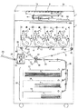
図7は、上下の第1と第2の定着ローラ41・42のそれぞれにローラ外側からマイクロ波を照射して加熱する系の定着装置40について、第1と第2の定着ローラ41・42のマイクロ波照射量のばらつきを補償する構成を示している。第1と第2の定着ローラ41・42の構成は実施例1の第1と第2の定着ローラ41・42と同様である。   FIG. 7 shows the fixing device 40 of the system in which the upper and lower first and second fixing rollers 41 and 42 are heated by irradiating microwaves from the outside of the rollers. The structure which compensates the dispersion | variation in microwave irradiation amount is shown. The configurations of the first and second fixing rollers 41 and 42 are the same as those of the first and second fixing rollers 41 and 42 of the first embodiment.

48はシールドボックス44内に配設したマイクロ波反射板(電磁波反射手段)である。導波路45は定着装置40の上部、記録材Pの搬入口44g寄りからシールドボックス44内にマイクロ波wを照射するように構成、配置されている。電磁波発生手段であるマイクロ波発生器(不図示)がシールドボックス44外に配設されている。導波路45は、マイクロ波発生器から発生したマイクロ波を上記の位置に導く。   Reference numeral 48 denotes a microwave reflection plate (electromagnetic wave reflection means) disposed in the shield box 44. The waveguide 45 is constructed and arranged to irradiate the microwave w into the shield box 44 from the upper part of the fixing device 40 and from the entrance 44g of the recording material P. A microwave generator (not shown) as electromagnetic wave generating means is disposed outside the shield box 44. The waveguide 45 guides the microwave generated from the microwave generator to the above position.

導波路45から照射されたマイクロ波wは、反射板48に当たる。反射板48は導波路45から照射されたマイクロ波wを上側の第1の定着ローラ41と下側の第2の定着ローラ42に均一に照射する。   The microwave w irradiated from the waveguide 45 hits the reflection plate 48. The reflection plate 48 uniformly irradiates the upper first fixing roller 41 and the lower second fixing roller 42 with the microwave w irradiated from the waveguide 45.

反射板48は、前記機能を発揮するため、第1の定着ローラ41にマイクロ波を反射する上側ローラ照射面48aと、第2の定着ローラ42にマイクロ波を反射する下側ローラ照射面48bとを有して構成されている。   In order to perform the function, the reflecting plate 48 has an upper roller irradiation surface 48 a that reflects microwaves to the first fixing roller 41, and a lower roller irradiation surface 48 b that reflects microwaves to the second fixing roller 42. It is comprised.

以上の構成により、内部に発熱層41c・42cを有する第1と第2の定着ローラ41・42はそれぞれほぼ同様に発熱し、発熱層の熱が各ローラ内部に配設された熱伝導層41d・42dによって拡散、均一化される。これにより、各ローラ41・42の外周に設けられた弾性層41e・42eの総表面を均一に加熱する事により、均質な定着画像を得ることが可能にできる。   With the above configuration, the first and second fixing rollers 41 and 42 having the heat generating layers 41c and 42c in the inside generate heat in substantially the same manner, and heat of the heat generating layer is provided in the heat conductive layer 41d disposed inside each roller. -Diffused and uniformized by 42d. Thereby, it is possible to obtain a uniform fixed image by uniformly heating the total surface of the elastic layers 41e and 42e provided on the outer circumferences of the rollers 41 and 42.

なお、本構成により上下の第1と第2の定着ローラ41・42はそれぞれ同様に加熱されるため、常温から定着温度への加熱温度立ち上げ時間を揃えることが可能になる。更には、一つのマイクロ波発生器43を共用に使用しながらにして、それぞれのローラ41・42の温度をほぼ同一に制御することが可能にできる。   Since the upper and lower first and second fixing rollers 41 and 42 are similarly heated by this configuration, it is possible to make the heating temperature rise time from the normal temperature to the fixing temperature uniform. Furthermore, it is possible to control the temperatures of the rollers 41 and 42 substantially the same while using one microwave generator 43 in common.

本実施例の定着装置40は、一経路の簡単な導波路45で電磁波wをシールドボックス44内に導く。そして、シールドボックス44内に導かれた電磁波wをシールドボックス44内に配置した反射板48を用いて、対の第1と第2の定着ローラ41・42に均等に電磁波が照射されるように構成した。これにより対のそれぞれのローラ41・42を同等に加熱ことができるので、簡単な構成ながら、効率的な電磁波加熱が可能にできる効果画得られる。   The fixing device 40 of this embodiment guides the electromagnetic wave w into the shield box 44 by a simple waveguide 45 having one path. Then, the electromagnetic wave w guided into the shield box 44 is used to uniformly irradiate the pair of first and second fixing rollers 41 and 42 using the reflector 48 disposed in the shield box 44. Configured. As a result, the pair of rollers 41 and 42 can be heated equally, so that an effect image can be obtained that enables efficient electromagnetic wave heating with a simple configuration.

参考例1における画像形成装置の概略構成を示す縦断面図A longitudinal sectional view showing a schematic configuration of the image forming apparatus in Reference Example 1 . 定着装置の概略構成を示す横断側面図Cross-sectional side view showing schematic configuration of fixing device 図2の(3)−(3)線に沿う縦断正面面Longitudinal front view along line (3)-(3) in FIG. 定着装置の動作を示す動作フローOperation flow showing the operation of the fixing device 定着装置の温調制御系統のブロック図Block diagram of temperature control system for fixing device 参考例2における定着装置の概略構成を示す縦断正面図Longitudinal front view showing a schematic configuration of the fixing device in Reference Example 2 . 実施例における定着装置の概略構成を示す横断側面図Cross-sectional side view showing a schematic configuration of the fixing device in the embodiment

40…定着ユニット(定着装置)、41…第1の加熱・加圧ローラ、42…第2の加熱・加圧ローラ、43…マイクロ波発生器、44…シールドボックス、45・46…導波路、41a・42a…ローラ回転軸、41b・42b…断熱層、41c・42c…発熱層、41d・42d…熱伝導層、41e・42e…弾性層、44g…記録材搬入口、44…記録材搬出口   DESCRIPTION OF SYMBOLS 40 ... Fixing unit (fixing apparatus), 41 ... 1st heating and pressure roller, 42 ... 2nd heating and pressure roller, 43 ... Microwave generator, 44 ... Shield box, 45, 46 ... Waveguide, 41a, 42a ... roller rotation shaft, 41b, 42b ... heat insulation layer, 41c, 42c ... heat generation layer, 41d, 42d ... heat conduction layer, 41e, 42e ... elastic layer, 44g ... recording material carry-in port, 44 ... recording material carry-out port

Claims (1)

記録材上の画像をニップ部にて加熱する第1の回転体と第2の回転体と、電磁波を発生する電磁波発生器と、を有する画像加熱装置において、
電磁波を遮蔽するシールドボックスと、前記電磁波発生器による電磁波を前記シールドボックス内へと導く導波路と、前記シールドボックス内に導かれた電磁波を前記第1の回転体および前記第2の回転体に向けて反射する電磁波反射手段と、を有することを特徴とする画像加熱装置。
In an image heating apparatus having a first rotating body and a second rotating body that heat an image on a recording material at a nip portion, and an electromagnetic wave generator that generates an electromagnetic wave,
A shield box that shields electromagnetic waves, a waveguide that guides electromagnetic waves from the electromagnetic wave generator into the shield box, and electromagnetic waves guided into the shield box to the first rotating body and the second rotating body. An image heating apparatus comprising: an electromagnetic wave reflecting means that reflects toward the screen.
JP2006052803A 2006-02-28 2006-02-28 Image heating device Expired - Fee Related JP4810255B2 (en)

Priority Applications (1)

Application Number Priority Date Filing Date Title
JP2006052803A JP4810255B2 (en) 2006-02-28 2006-02-28 Image heating device

Applications Claiming Priority (1)

Application Number Priority Date Filing Date Title
JP2006052803A JP4810255B2 (en) 2006-02-28 2006-02-28 Image heating device

Publications (3)

Publication Number Publication Date
JP2007232913A JP2007232913A (en) 2007-09-13
JP2007232913A5 JP2007232913A5 (en) 2009-03-12
JP4810255B2 true JP4810255B2 (en) 2011-11-09

Family

ID=38553589

Family Applications (1)

Application Number Title Priority Date Filing Date
JP2006052803A Expired - Fee Related JP4810255B2 (en) 2006-02-28 2006-02-28 Image heating device

Country Status (1)

Country Link
JP (1) JP4810255B2 (en)

Family Cites Families (5)

* Cited by examiner, † Cited by third party
Publication number Priority date Publication date Assignee Title
JPS5719963U (en) * 1980-06-30 1982-02-02
JPS5797560A (en) * 1980-12-11 1982-06-17 Canon Inc Fixing device
JPS57104152A (en) * 1980-12-22 1982-06-29 Canon Inc Form detector
JPS57124381A (en) * 1981-01-26 1982-08-03 Canon Inc Fixing device
JPH11214143A (en) * 1998-01-30 1999-08-06 Matsushita Electric Ind Co Ltd High frequency heater

Also Published As

Publication number Publication date
JP2007232913A (en) 2007-09-13

Similar Documents

Publication Publication Date Title
JP4795054B2 (en) Image heating device
CN108931907B (en) Fixing device and image forming apparatus
CN104166331B (en) Fixing device and imge forming apparatus
JP6287279B2 (en) Fixing apparatus and image forming apparatus
US9207589B2 (en) Fixing device and image forming apparatus including same
US7945198B2 (en) Fixing device and image forming apparatus comprising same
CN102207718B (en) Fixing device and image forming apparatus including same
US8244166B2 (en) Fusing device and image forming apparatus employing the same
CN104049504A (en) Fixing Device And Image Forming Apparatus
US9104151B2 (en) Fixing device and image forming apparatus
CN103676574A (en) Fixing device and image forming apparatus
JP2005338724A (en) Fixing device and image forming apparatus
JP5993820B2 (en) Fixing apparatus and image forming apparatus
JP2016014867A (en) Fixing device and image forming apparatus
EP0601879B1 (en) A fixing device with sheet curl compensation
JP4810255B2 (en) Image heating device
JP5938964B2 (en) Fixing apparatus, image forming apparatus, and heat amount adjusting method
JP5765031B2 (en) Fixing apparatus and image forming apparatus
US8918038B2 (en) Fixing device and image forming apparatus incorporating same
JP2010211080A (en) Fixing device, and image forming apparatus
JP4933113B2 (en) Image heating device
JP6578754B2 (en) Fixing apparatus and image forming apparatus
JP4206841B2 (en) Fixing device and image forming apparatus using the same
JP2014132310A (en) Fixing apparatus and image forming apparatus
JP2014056007A (en) Fixing device and image forming device

Legal Events

Date Code Title Description
A521 Written amendment

Free format text: JAPANESE INTERMEDIATE CODE: A523

Effective date: 20090126

A621 Written request for application examination

Free format text: JAPANESE INTERMEDIATE CODE: A621

Effective date: 20090126

A977 Report on retrieval

Free format text: JAPANESE INTERMEDIATE CODE: A971007

Effective date: 20110427

A131 Notification of reasons for refusal

Free format text: JAPANESE INTERMEDIATE CODE: A131

Effective date: 20110510

A521 Written amendment

Free format text: JAPANESE INTERMEDIATE CODE: A523

Effective date: 20110708

TRDD Decision of grant or rejection written
A01 Written decision to grant a patent or to grant a registration (utility model)

Free format text: JAPANESE INTERMEDIATE CODE: A01

Effective date: 20110809

A01 Written decision to grant a patent or to grant a registration (utility model)

Free format text: JAPANESE INTERMEDIATE CODE: A01

A61 First payment of annual fees (during grant procedure)

Free format text: JAPANESE INTERMEDIATE CODE: A61

Effective date: 20110822

FPAY Renewal fee payment (event date is renewal date of database)

Free format text: PAYMENT UNTIL: 20140826

Year of fee payment: 3

LAPS Cancellation because of no payment of annual fees