JP4810056B2 - Cathode for high emission X-ray tube - Google Patents
Cathode for high emission X-ray tube Download PDFInfo
- Publication number
- JP4810056B2 JP4810056B2 JP2003281406A JP2003281406A JP4810056B2 JP 4810056 B2 JP4810056 B2 JP 4810056B2 JP 2003281406 A JP2003281406 A JP 2003281406A JP 2003281406 A JP2003281406 A JP 2003281406A JP 4810056 B2 JP4810056 B2 JP 4810056B2
- Authority
- JP
- Japan
- Prior art keywords
- cathode
- emitter
- backing
- anode
- opening
- Prior art date
- Legal status (The legal status is an assumption and is not a legal conclusion. Google has not performed a legal analysis and makes no representation as to the accuracy of the status listed.)
- Expired - Lifetime
Links
Images


Classifications
-
- H—ELECTRICITY
- H01—ELECTRIC ELEMENTS
- H01J—ELECTRIC DISCHARGE TUBES OR DISCHARGE LAMPS
- H01J35/00—X-ray tubes
- H01J35/02—Details
- H01J35/14—Arrangements for concentrating, focusing, or directing the cathode ray
- H01J35/153—Spot position control
-
- H—ELECTRICITY
- H01—ELECTRIC ELEMENTS
- H01J—ELECTRIC DISCHARGE TUBES OR DISCHARGE LAMPS
- H01J35/00—X-ray tubes
- H01J35/02—Details
- H01J35/04—Electrodes ; Mutual position thereof; Constructional adaptations therefor
- H01J35/06—Cathodes
- H01J35/066—Details of electron optical components, e.g. cathode cups
-
- H—ELECTRICITY
- H01—ELECTRIC ELEMENTS
- H01J—ELECTRIC DISCHARGE TUBES OR DISCHARGE LAMPS
- H01J35/00—X-ray tubes
- H01J35/02—Details
- H01J35/14—Arrangements for concentrating, focusing, or directing the cathode ray
- H01J35/147—Spot size control
Description
本発明は、一般的にX線管に関し、より具体的には、X線管のカソード構成に関する。 The present invention relates generally to x-ray tubes, and more specifically to the cathode configuration of x-ray tubes.
現在入手可能な医療用X線管は一般的に、エミッタとカップとを有するカソード組立体を含む。カソード組立体は、一般的に平面の金属又は複合構造体であるX線管アノード又はターゲットに面するように配向される。カソードとアノードとの間の空間は真空にされる。 Currently available medical x-ray tubes generally include a cathode assembly having an emitter and a cup. The cathode assembly is oriented to face an x-ray tube anode or target, which is typically a planar metal or composite structure. The space between the cathode and anode is evacuated.
一般的なカソード設計の欠点は、一般的に螺旋状に巻かれたタングステン線フィラメントを含むエミッタが、どちらかと言えば大きくなりがちであり、電子がフィラメント表面の全ての表面から放射状に外向きに放出されることである。従って、全電子軌道がその初期の発散運動からアノード表面上の極めて小さな焦点に向かって向け直されるように、極めて調整された電位分布を真空中に作り出すようにカップは設計されなければならない。このことは通常、均一にバイアスされたカソードカップを、フィラメントの極めて近傍において、電場が受動的に成形されて焦点を生じるように注意深く機械加工されたプロファイルを有するように構成することによってなされる。設計目的のためには、コイル状フィラメントを中実の放出円筒として取り扱い、そのコイルの個々の巻き線レベルにつての詳細を無視しても通常は十分である。また、焦点長さはその幅を大きく変えるものではないエミッタ・カップの変更によって多かれ少なかれ個別に設定されることができるので、その二次元形状全体ではなくて焦点幅のみを関心の対象とすることで通常は十分である。しかしながら、たとえこの設計の自由度をもってしても、そのような調整された電場を生成し、小さな焦点幅を生じるようにカップを設計することは実際には困難である。現在の最先端技術レベルは、アノード上の0.1ミリメートル幅の焦点上に収束させることができる、即ちビーム圧縮比を10とすることができる、およそ1ミリメートルの主要直径をもつフィラメント・コイルとする程度である。 The disadvantage of a typical cathode design is that the emitter, which typically includes a spirally wound tungsten wire filament, tends to be rather large, with electrons going radially outward from all surfaces of the filament surface. Is to be released. Therefore, the cup must be designed to create a highly tuned potential distribution in the vacuum so that all electron trajectories are redirected from their initial divergent motion toward a very small focal point on the anode surface. This is typically done by constructing a uniformly biased cathode cup with a profile that is carefully machined so that the electric field is passively shaped to produce a focus in the immediate vicinity of the filament. For design purposes, it is usually sufficient to treat the coiled filament as a solid discharge cylinder and ignore the details about the individual winding levels of the coil. Also, since the focal length can be set more or less individually by changing the emitter cup, which does not significantly change its width, only focus width, not the entire two-dimensional shape, is of interest. Usually it is enough. However, even with this design freedom, it is actually difficult to design a cup to produce such a tuned electric field and produce a small focal width. The state of the art state of the art is a filament coil with a major diameter of approximately 1 millimeter that can be focused on a 0.1 millimeter wide focus on the anode, ie a beam compression ratio of 10. It is a grade to do.
しかしながら、医療用画像形成における最近の進歩は、上述の技術を使用して得られることができるよりも大きな電子ビーム電流とより良好な電子ビーム光学機器とを必要とする。焦点におけるより高い電子ビーム電流密度に到着するための1つの方法は、より大きな熱電子エミッタ面積を使用して開始し、引き続いてより高い電子ビーム圧縮比(焦点面積をフィラメントの放出面積で除した比によって定義される)と組み合わせすることである。電子エミッタの普遍的な制約は、カソードとアノードとの間で計測された場合の正味放出電流が、エミッタの一次放出電流を増大させることによってただ無制限に増大はされ得ないということである。本明細書中で使用する場合、一次放出とは、エミッタ表面から出ていく電子を意味し、その表面へ戻る如何なる電子も含まない。もっと正確に言えば、エミッタにおける正味放出電流密度は制限される。熱電子の電子放出は、約4A/cm2に制限される。正味放出電流は、一次放出電流から、エミッタ表面へ戻る全ての電子電流を差し引いたものである。熱電子エミッタにおける低い加熱電流及び低いエミッタ温度に対応する極めて低い一次放出電流密度の下では、この正味放出電流密度は、一次放出電流密度のあらゆる増大にほぼ正比例して増大することになる。逆に、極めて高い一次放出電流密度の下では、エミッタ表面の直ぐ前での電子密度は、電子雲の自己電荷がカソード−アノード電位差によって生じたエミッタ表面における電場を完全に妨害するほど高くなる。この後者の状態は、飽和エミッタと呼ばれ、一次電流密度が更に増大しても、感知できるほどに正味放出電流を増大させない。これら2つの極限状態の間に、滑らかな遷移状態があり、そこでは、一次放出電流密度における増大は、正味放出電流における比例した増大よりも小さい増大を生じ、多くの場合、実際のX線管は、この遷移状態において動作する。全ての電子エミッタは、エミッタ材料及び放出機構とは関係なく、この基本的プロセスによって制約される。 However, recent advances in medical imaging require greater electron beam current and better electron beam optics than can be obtained using the techniques described above. One way to arrive at a higher electron beam current density at the focus starts with a larger thermionic emitter area, followed by a higher electron beam compression ratio (the focus area divided by the emission area of the filament). Is defined by the ratio). The universal limitation of electron emitters is that the net emission current, measured between the cathode and anode, cannot be increased indefinitely by increasing the primary emission current of the emitter. As used herein, primary emission refers to electrons that exit the emitter surface and does not include any electrons that return to that surface. More precisely, the net emission current density at the emitter is limited. Thermionic electron emission is limited to about 4 A / cm 2 . The net emission current is the primary emission current minus all electron currents returning to the emitter surface. Under very low primary emission current densities corresponding to low heating currents and low emitter temperatures in thermionic emitters, this net emission current density will increase approximately in direct proportion to any increase in primary emission current density. Conversely, under a very high primary emission current density, the electron density just before the emitter surface is so high that the self-charge of the electron cloud completely obstructs the electric field at the emitter surface caused by the cathode-anode potential difference. This latter condition is called a saturated emitter and does not appreciably increase the net emission current as the primary current density further increases. There is a smooth transition state between these two extreme states, where an increase in the primary emission current density results in a smaller increase than a proportional increase in the net emission current, often the actual x-ray tube Operates in this transition state. All electron emitters are constrained by this basic process, regardless of emitter material and emission mechanism.
カソードの全体的能力を特徴付けるための有用な性能指数は、比I/V3/2として定義されるパービアンスであり、ここで、Iは正味電子電流であり、Vはカソード−アノード間の電位差である。更に、真空中における電子の自己電荷は、電位を変える場合があり、時として焦点ボケと呼ばれる、焦点寸法の拡大のような望ましくない変化を引き起こす可能性がある。従って、正味電流についての設計目標を満たすことができ、更にそれら固有の飽和電流密度よりもはるかに下で作動するカソード設計は、利点があるものとなり得る。最終的に、熱電子エミッタの耐用年数とその作動温度との間にはトレードオフが通常は存在し、より低い温度、従ってより低い一次放出電流密度の下でエミッタを作動させることが望ましいこととなる。 A useful figure of merit for characterizing the overall capacity of the cathode is the pervance defined as the ratio I / V 3/2 , where I is the net electron current and V is the cathode-anode potential difference. is there. In addition, the self-charge of electrons in a vacuum can change the potential and can cause undesirable changes, such as increased focal dimensions, sometimes referred to as defocus. Thus, cathode designs that can meet design goals for net current and operate well below their inherent saturation current density can be advantageous. Finally, there is usually a trade-off between the service life of a thermionic emitter and its operating temperature, and it is desirable to operate the emitter at a lower temperature and hence a lower primary emission current density. Become.
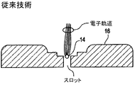
一般的カソード設計の別の欠点は、電子を適切に収束させるために必要とされるカップ設計が、カソードの飽和電流、従ってフィラメントが該カップから離れて自由な空間において作動される場合に期待されるX線放出に優る最大取得可能X線放出における大きな減少を生じることである。具体的には、螺旋状巻き線フィラメントからの最初の放射方向に向けられた電子分布が小さな焦点上へと向け直されなければならないという前述の必要性により、フィラメント・エミッタはどちらかと言えば狭いスロット内に置かれることになる。残念なことに、このことが、フィラメントの前面に対して法線をなした電場を、カソード−アノード間の隙間内に存在する、V/Lのオーダで表される平均電場よりも著しく低い値に減少させる。ここで、Vはカソードとアノードとの間の電位であり、Lはカソード−アノード間隔である。電子放出が全くない状態におけるエミッタ表面に対して法線をなした電場の強度は、フィラメント表面上の各点の飽和電流密度を決定する。更に、エミッタ表面に対して法線をなした電場の強度は、アノードに最も近い、フィラメントの表面部分上のみが最も高くなり、該強度はこの一点から離れるにつれて減少し、従って、飽和電流密度はこの1つの特定位置から離れるにつれて減少する。原則として、放出面積は、より高い全放出電流を得るために常に増大させることができるが、上で述べたように、焦点寸法の望ましくない増大も招くことなくフィラメント寸法を増大させることは困難である。 Another drawback of the general cathode design is that the cup design required to properly focus the electrons is expected when the cathode saturation current and hence the filament is operated in free space away from the cup. A significant reduction in the maximum obtainable X-ray emission over the X-ray emission. Specifically, filament emitters are rather narrow due to the aforementioned need that the electron distribution directed from the first spiral winding filament must be redirected to a small focal point. Will be placed in the slot. Unfortunately, this means that the electric field normal to the front face of the filament is significantly lower than the average electric field present in the cathode-anode gap, expressed in the order of V / L. Reduce to. Where V is the potential between the cathode and anode, and L is the cathode-anode spacing. The intensity of the electric field normal to the emitter surface in the absence of any electron emission determines the saturation current density at each point on the filament surface. In addition, the intensity of the electric field normal to the emitter surface is highest only on the surface of the filament closest to the anode, and the intensity decreases with increasing distance from this point, so the saturation current density is Decreases with distance from this one particular location. In principle, the emission area can always be increased to obtain a higher total emission current, but as mentioned above, it is difficult to increase the filament size without incurring an undesirable increase in focal size. is there.
従来のフィラメント・カップカソード設計の別の制約は、フィラメント上の様々な位置から放出された電子の軌道が、該電子がカソードからアノードへ移動するときに互いに交差することがないような層流電子ビームに似た何らかの電子ビームを形成することは実際には極めて困難であることである。その結果、アノード表面上の焦点幅を横切る電流密度の空間分布は、最良の変調伝達関数、従って最最良の画質を生じるガウス分布にならない。その代わりに、焦点の電流分布は、一般的に二重ピーク状になる。ターゲット上の焦点内のピーク電子電流は、アノードのピーク温度能力によって制約される。従って、実際のピーク電流密度が、任意のアノード設計についての別の方法の等価ガウス空間分布のピーク電流密度を超える程度にまで、全電流、従って最大達成可能X線フルエンスが減少されることになる。電子流れは、電子電流の望ましいガウス空間分布を作り出すために必ずしも層流に近いものである必要はないが、従来のフィラメント・カップカソード設計によって作り出された電子ビームの高度に非層流的な性質は、ガウス焦点の形成を実際には極めて困難にする。従来のフィラメント・カップカソード設計の別の制約は、異なった(例えば、大きい又は小さい)焦点のための新規カソードを設計する必要なく焦点寸法を変更することが実際には極めて困難であることである。
より高い放出電流と、より小さな焦点幅と、より良好な変調伝達関数とを同時に提供するエミッタ・カップカソードは、これまで得られていない。従って、上述の欠点を克服するエミッタ・カップX線管カソードを提供することは望ましい。より高いビーム電流を、より小さくかつ可変的な寸法にされた焦点へ収束させる能力と組み合わせて放出能力を改善することの重要性は、現行の熱電子放出技術を使用する医療用画像形成システムの画質を改善する必要性から明確に求められている。 An emitter-cup cathode that simultaneously provides higher emission current, smaller focal width, and better modulation transfer function has not been obtained. Accordingly, it would be desirable to provide an emitter cup x-ray tube cathode that overcomes the above-mentioned drawbacks. The importance of improving emission capability in combination with the ability to focus higher beam currents to smaller and variable sized focal points is the importance of medical imaging systems using current thermionic emission technology. It is clearly required because of the need to improve image quality.
従来のカソード設計を用いて別の方法で得ることができるよりも実質的に大きいパービアンス及びビーム圧縮比の電子ビームを提供するように構成された、エミッタと差動バイアスされたエミッタ・カップとを有するX線管のための方法と装置が開示される。1つの実施形態において、X線源を作動させるための方法は、ビーム経路に沿ってカソードから電子ビームを放出する段階と、差動バイアスされたカソードによって双極子場を生成し、電子ビームを双極子場及び差動バイアスと相互作用させて、該電子ビームをアノード上の焦点上へ集束させかつ偏向させ、該アノードからX線が放出されるようにする段階とを含む。双極子場は、差動バイアスを変更するための手段を用いて修正されて、アノード上への電子ビームを成形し、所定の電子ビーム圧縮比を生成する焦点寸法を生じさせる。 An emitter and a differentially biased emitter cup configured to provide an electron beam with a substantially higher perveance and beam compression ratio than otherwise obtainable using conventional cathode designs. A method and apparatus for having an x-ray tube is disclosed. In one embodiment, a method for operating an x-ray source includes emitting an electron beam from a cathode along a beam path and generating a dipole field with a differentially biased cathode to divert the electron beam into a dipole. Interacting with the child field and differential bias to focus and deflect the electron beam onto a focal point on the anode such that X-rays are emitted from the anode. The dipole field is modified using means for changing the differential bias to shape the electron beam onto the anode and produce a focal dimension that produces a predetermined electron beam compression ratio.
別の実施形態においては、X線管のためのカソードが開示される。カソードは、アノードに対向し、該アノードから間隔を置いて配置されたカソード組立体を含む。カソードは、X線管の作動中にアノードに対して負の電位に維持される。カソード組立体は、X線管作動中に電子ビームをアノード上の焦点に対して放出するためのエミッタと、該エミッタの第1の側に配置された、それによって形成された開口を有するカソード前面部材とを含む。バッキングが、エミッタの第2の側に配置され、バッキング絶縁体を介してカソード前面部材に動作可能に接合される。カソード組立体は更に、カソード内に差動バイアスを加えて、焦点寸法を可変的に変更するための手段を含む。カソードバッキングは、Vハ゛ックでバイアスされ、カソード前面部材の開口は、V開口で個別にバイアスされ、エミッタは、Vエミッタでバイアスされており、Vハ゛ック<Vエミッタの場合には、Vハ゛ック≧Vエミッタの場合よりも大きなビーム圧縮比が得られる。 In another embodiment, a cathode for an x-ray tube is disclosed. The cathode includes a cathode assembly opposite the anode and spaced from the anode. The cathode is maintained at a negative potential relative to the anode during operation of the x-ray tube. The cathode assembly has an emitter for emitting an electron beam to a focal point on the anode during x-ray tube operation, and a cathode front surface formed by an aperture disposed on the first side of the emitter. Member. A backing is disposed on the second side of the emitter and is operatively joined to the cathode front member via a backing insulator. The cathode assembly further includes means for variably changing the focal spot size by applying a differential bias within the cathode. Cathode backing is biased with V back , cathode front member openings are individually biased with V openings , emitters are biased with V emitters , and if V back <V emitter , V back ≧ V A larger beam compression ratio is obtained than in the case of the emitter .
図1及び図2は、エミッタ14とカップ16とを有するカソード12を含む従来のX線管10を示す。カソード12は、一般的に平面の金属又は複合構造体であるX線管のアノード18又はターゲットに面するように配向される。高X線束が必要な多くの用途において、アノード自体は、焦点におけるピークアノード温度を容認可能な値に保つために、高速(一般的に、1000から10,000回転/分)で回転させられる円盤である。カソード組立体は一般的に、アノードに対して20から200kVだけ負に保持される。カソードとアノードとの間の空間即ち空隙は、真空にされて間隙の電圧隔離能力を改善し、電子−原子衝突による散乱を減少させる。エミッタ14は一般的に、螺旋状に巻かれたタングステン線フィラメントであり、該タングステン線フィラメントは、数アンペアの電流を該線に通すことによって、電子の熱電子放出に十分な温度にまで加熱される。エミッタ14は、カップ16内に配置される。カソードとアノードとの間の電位差は、熱電子的に放出された電子を所望の運動エネルギにまで加速し、それらをアノード上の適切な線状焦点へ導き、そこでは続いてアノード材料の特性である制動放射の類のプロセスによってX線が発生させられる。カップの形状は、電子ビームがアノードに衝突するときに所望の電子ビーム断面、つまり焦点寸法及び形状を形成するように選択される。真空中の電位は、電位又はバイアスを、エミッタとカップとの間に加えることによって更に変更できる。実際のカソード組立体は、全放出電流、焦点の線幅、及びその他の性能指標との間で最善の折衷を作り出すように設計される。
1 and 2 show a
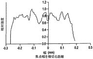
図3は、図1に示されたフィラメント−カップのような、従来のフィラメント−カップ設計に一般的な、二重ピークの焦点電流分布を示すグラフである。上で説明したように、これは、そのような従来のフィラメント−カップカソード設計によって発生させられた電子ビームの性質が極めて非層流であることの結果であり、そのことは、焦点電流のガウス分布の形成を実際問題として極めて困難にする。 FIG. 3 is a graph showing the double peak focus current distribution typical of a conventional filament-cup design, such as the filament-cup shown in FIG. As explained above, this is a result of the very non-laminar nature of the electron beam generated by such a conventional filament-cup cathode design, which is a Gaussian of the focal current. The formation of the distribution is extremely difficult as a practical problem.
本開示の例示的な実施形態によれば、ほぼ平坦な焦点電流分布を作り出すエミッタ−カップカソード構成が提供される。図4は、以下に説明する本開示の例示的な実施形態を使用してコンピュータ・シミュレーションした、そのような望ましいガウス焦点電流分布を示すグラフであり、該ガウス焦点電流分布は、より良好な変調伝達関数、従ってX線画像形成における最善の画質を生じる。 According to an exemplary embodiment of the present disclosure, an emitter-cup cathode configuration is provided that creates a substantially flat focal current distribution. FIG. 4 is a graph illustrating such a desired Gaussian focal current distribution, computer simulated using an exemplary embodiment of the present disclosure described below, where the Gaussian focal current distribution is better modulated. The transfer function and hence the best image quality in x-ray imaging is produced.
図5及び図6は、本開示の例示的な実施形態によるエミッタ−カップX線管カソード22を示す。カソード22は、空洞26内に配置されたエミッタ24を含む。本開示の好ましい実施形態(図6を参照)によれば、エミッタ24はコイル状フィラメントであり、該フィラメントの少なくとも1側は、数平方ミリメータのオーダの放出面積を持つほぼ平面の形状を有する。本明細書で使用される「ほぼ平面の」とは、巻かれた線フィラメントと区別されるが必ずしも平坦とは限らない形状を意味する。つまり、表面は多少湾曲を有していてもよい。
5 and 6 illustrate an emitter-cup
従来のコイル状フィラメントとは対照的に、ほぼ平面のエミッタが有する1つの利点は、1つの面から放出された電子がほぼ同一方向(その面に対して法線をなした)に移動することであり、一方、コイル(又はコイルの一部分、例えば半分でさえ)から放出された電子は、組織化された正味集合運動を殆どもたない。しかしながら、いずれの場合においても、有限エミッタ温度により生じるランダム成分が存在するので、電子の運動は全体が集合的ということではない。コイル状フィラメントの場合、発散電子軌道の全てを小さな焦点に集めるように電位を成形するのは、極めて困難であるが、他方、ほぼ平坦なエミッタの場合、電子軌道は既にほぼ適切な方向になっており、電位は、同一焦点を作り出すようにその軌道を摂動させることのみに必要とされる。 In contrast to conventional coiled filaments, one advantage of a substantially planar emitter is that electrons emitted from one surface move in approximately the same direction (normal to that surface). On the other hand, electrons emitted from the coil (or even part of the coil, eg even half) have little organized net collective motion. However, in any case, there is a random component caused by the finite emitter temperature, so the electron motion is not totally collective. In the case of a coiled filament, it is very difficult to shape the potential so that all of the diverging electron trajectory is collected at a small focal point, while for a nearly flat emitter, the electron trajectory is already in a nearly appropriate direction. The potential is only needed to perturb its trajectory to create the same focus.
あらゆる適切なエミッタ材料と適切な電子放出モードが、本開示のエミッタ−カップカソードに対して使用できる。適切なエミッタ材料の1例は、1から数ミルの例示的な範囲の厚さを有するタングステン箔である。タングステン箔は、適切な金属成形技術を使用することで、該箔を精密に成形し、パターン化し、また別の方法で細工することができる利点をもたらす。また、該タングステン箔は、電流をタングステンに通すことにより又は間接的な方法により抵抗加熱されて、熱電子メカニズムによって電子を放出することができる。 Any suitable emitter material and suitable electron emission mode can be used for the emitter-cup cathode of the present disclosure. One example of a suitable emitter material is a tungsten foil having a thickness in the exemplary range of 1 to several mils. Tungsten foil provides the advantage that by using an appropriate metal forming technique, the foil can be precisely shaped, patterned and otherwise crafted. The tungsten foil can also be heated by resistance by passing an electric current through tungsten or by an indirect method to emit electrons by a thermionic mechanism.
図6の実施形態においては、エミッタ24は、湾曲した側面27とほぼ平面の前面28とを有する全体的なブロックとして示されている。エミッタ・ブロックは、空洞26内に配置される。エミッタは、ターゲット表面に面しており、該ターゲット表面は、エミッタに対して幾らかの正の電位(Vターケ゛ット)、一般的には例えば医療用画像形成用途においては20〜200kVに保持される。エミッタによって発生された電子は、電位差によって加速され、アノード18に衝突し、該アノードにおいて、特性X線と制動X線の両方が生成される。
In the embodiment of FIG. 6, the
多くの従来の医療用X線管においては、アノードは、理想的にされた点又は線になっておらず、或いは、実用的電子銃の穴あきアノードの場合でさえそのようになっておらず、むしろ、アノードは平面に近い。ほぼ平面のアノードにおいて、電場線は、所望の焦点から多少放射方向外向きに延びるのではなくて、アノード表面に対して法線をなしており、アノードが点又は線により厳密に近似している場合に比べて、カソードにより電子軌道をより強力に収束させる必要があることになる。 In many conventional medical x-ray tubes, the anode is not an idealized point or line, or even in the case of a practical electron gun perforated anode. Rather, the anode is close to a plane. In a nearly planar anode, the electric field lines do not extend somewhat radially outward from the desired focal point, but are normal to the anode surface, and the anode is closely approximated by a point or line. Compared to the case, it is necessary to focus the electron orbit more strongly by the cathode.
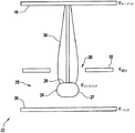
図5及び図6の実施形態は、線状焦点の平面アノードをもつX線管で用いるのに最適化されたカップ構成を示す。該カップ構成は以下のように、エミッタ24と、カソード前面部材32によって形成された開口30とを含む。部材32内の開口30は、エミッタ24により形成された電子ビーム34の形成を完成させるような電位(V開口)になっている。エミッタ24は、該エミッタ24のもう一方の側においてカソード前面部材32と向かい合っているカソードバッキング36から延びる。エミッタ24は、該エミッタ24の2つの電極38を介してカソードバッキング36から延び、該2つの電極38はそれぞれの周りに絶縁体40を有し、該絶縁体40が、(Vハ゛ック)の電位を有するカソードバッキング36から絶縁して、エミッタ24を電位(Vエミッタ)に維持する。カソードバッキング36は、バッキング絶縁体42を介してカソード前面部材32との間で電気的絶縁が維持された状態で、該カソード前面部材32に対して動作可能に接合される。カソードバッキング36は、平面の表面を有するように示されているが、該バッキングが、別の幾何学形状を有してもよいことは当業者には理解されるであろう。更に、開口30は、固定スロットに限定されるものではなく、ビーム34の長さプロファイルを制限するように調節できるタブ(バイアスされた)を含むことができる。カソード組立体22は、差動バイアスされて、望ましい層流であり、共心であり、かつ均質である電子ビームに極めて近似したものを作り出す。
The embodiment of FIGS. 5 and 6 shows a cup configuration optimized for use in an x-ray tube having a planar anode with a linear focus. The cup configuration includes an
差動バイアスとは、例示的な実施形態において、開口30におけるカソード前面部材32を(V開口)で、バッキング36を(Vハ゛ック)で、カソード(図5)のフィラメント(Vフィラメント)を有するエミッタ24を(Vエミッタ)で、個別にバイアスすることを意味する。フィラメントの周りにおけるカップの幾何学形状によって達成される、従来のカソードにおける電場の受動的成形とは対照的に、個別バイアス方式は、電子ビーム34を抽出し加速するのに必要な電場の能動的成形を可能にする。従って、カソードカップ構成要素を別々にバイアスすることはまた、焦点寸法の範囲全体にわたっての、該焦点寸法の連続的調節も可能にする。例えば、血管X線画像形成管においては、この範囲は0.3mmから1.0mmまでの焦点とすることができる。
In the exemplary embodiment, the differential bias is an emitter having a
焦点においてより高い電子ビーム電流密度に到達する1つの例示的な方法は、より大きい熱電子エミッタ面積からの熱電子の電子放出を開始し、引き続いてより高い電子ビーム圧縮比(焦点面積をフィラメントの放出面積で除した比によって定義される)と組み合わせることである。従来のカソードにおける放出が制約される問題点は、コイル状フィラメント中に直線部分を含むことによって最適化される。 One exemplary method of reaching a higher electron beam current density at the focal point initiates thermionic electron emission from a larger thermionic emitter area, followed by a higher electron beam compression ratio (focal area less than that of the filament). Defined by the ratio divided by the release area). The problem of limiting emission in conventional cathodes is optimized by including a straight portion in the coiled filament.
差動バイアス(Vハ゛ック<Vフィラメント)は、より大きいビーム圧縮比を可能にする改善されたビーム光学機器を提供する。これは、一部は、放出面積の最も大きな部分が平坦な形状であることによるものである。第2に、これは、フィラメント表面近くに差動的な負の電位(つまり、Vハ゛ック)が存在することにより、フィラメントの湾曲部分からの電子放出が減少することによって達成される。例示的な実施形態においては、この差動的な負の電圧は、約10kVよりも小さく、一方、ビーム電位は約80から約120kVの間である。 Differential bias (V back <V filament ) provides an improved beam optics that allows for greater beam compression ratios. This is due in part to the fact that the largest part of the emission area is flat. Second, this is accomplished by reducing electron emission from the curved portion of the filament by the presence of a differential negative potential (ie, V- back ) near the filament surface. In the exemplary embodiment, this differential negative voltage is less than about 10 kV, while the beam potential is between about 80 and about 120 kV.
ビーム光学機器の更なる改善は、フィラメントの幾何学形状を最適化することによって、例えば、直線部分を凸状部分で置き換えることによって達成することができる。また、長さ方向に見た場合に真直ぐなフィラメントによって差動バイアスされたカソードを、長さ方向に凸形状をなすフィラメントを使用して更に改善することが考えられる。これは、更に高い圧縮比を可能にするであろう。従来のカソードに比較して、例示的な実施形態におけるコイル直径は、フィラメント・エミッタ24近くにあるカソード組立体の前面を(V開口)で及びバッキングを(Vハ゛ック)で個別にバイアスすることを使用して電子ビーム形成を能動的に成形することによる可変差動バイアスされたカソードを使用することで、一層大きくなる。結果として、フィラメントの線直径は増大させることができる。線直径が大きければ、該フィラメントが同一の相対温度の下で作動される場合に、フィラメント寿命が増大することは、当業者には分かるであろう。
Further improvements in beam optics can be achieved by optimizing the filament geometry, for example by replacing the straight part with a convex part. Further, it is conceivable to further improve the cathode differentially biased by a straight filament when viewed in the length direction by using a filament having a convex shape in the length direction. This will allow higher compression ratios. Compared to a conventional cathode, the coil diameter in the exemplary embodiment is such that the front of the cathode assembly near the
例示として図7を参照すると、電子軌道の個別処理を行なっている場合のエミッタ−カップの様々な部分を見ることができる。放出表面28の形状が平面であることは、初期電子運動が焦点に向かう、つまり、電子速度の初期熱分布により達成され得る範囲に向かうことを保証する。カソードバッキング36におけるVハ゛ックは、電子ビームの端縁に沿って電位を成形する。開口30におけるV開口は、中間エネルギの電子ビームについて最終ビーム処理を行なうために使用される。開口を越えても電子の運動量は充分に大きいので、更なる誘導は必要でもないし、特に有意義でもなく、また、電子は、残存のカソード−アノード電位差によって、該電子が焦点に到着するまで加速される。
Referring to FIG. 7 as an illustration, various portions of the emitter-cup can be seen when performing individual processing of electron trajectories. The planar shape of the
都合がいいことには、図5及び図6の実施形態は、与えられた幅、又はより一般的には、与えられた表面面積を有するエミッタに対して、結果として小さな焦点幅になり、従って、放出電流を犠牲にすることなく高いビーム圧縮比を生じる。従来技術においては、カソードカップはフィラメントに対して負にバイアスされ、従ってパービアンスを減少させる。ここに開示した例示的な差動バイアスされたカソードは、一次に対するパービアンスを変化させない、つまり、V開口とVハ゛ックとを加えたものは、Vハ゛ックを変更することによって収束が行なわれるが、ほぼ一定に維持される。 Conveniently, the embodiments of FIGS. 5 and 6 result in a small focal width for an emitter having a given width, or more generally a given surface area, and thus Produces a high beam compression ratio without sacrificing the emission current. In the prior art, the cathode cup is negatively biased with respect to the filament, thus reducing the perveance. The exemplary differentially biased cathode disclosed herein does not change the perveance relative to the primary, i.e., the addition of the V opening and V back is converged by changing the V back , but is nearly Maintained constant.
次に図7を参照すると、別の例示的な実施形態が示されており、この実施形態は、開口32とバッキング36電極との間に挿入された第2の電極52を有する。電場を成形することに対する自由度を増大させるために、前部電極(つまり、開口32)とバッキング36との間に多重の電極/開口を挿入することが考えられる。例えば、2つ又はそれ以上の開口を前後の電極32、36間に挿入することができる。しかしながら、製造のためには、電極は最少(つまり、2つの電極、開口32及びバッキング36)に制限することが望ましい。
Referring now to FIG. 7, another exemplary embodiment is shown, which has a
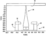
図8は、図5及び図6のエミッタ−カップカソードのようなエミッタ−カップカソードから得られた電子ビーム34の形成と電子ビームのプロファイルとを示す。図8は、カソード組立体22の中心において断面で表示された、差動バイアスされたカソードについてのコンピュータ・シミュレーションである。ビーム幅の集束が示されている。シミュレーションの目的で、フィラメントは、長さ方向において真直ぐであると仮定される。電子ビームは、0.5mm焦点に集束される。シミュレーションは、上で説明した物理的理由から線状焦点をシミュレーションするために、図6に示すのと同様な二次元断面として近似できるカソード−アノード幾何学形状の幾何学的構成を使用して開始される。(代わりに、点焦点を作り出すことを意図した設計をシミュレーションするためには、円筒対称を仮定することができる。)カソード及びアノード表面は、特定電位において完全導体であると仮定される。より具体的には、Vハ゛ックは(−4.2kV)であり、Vフィラメントは(0V)であり、V前面(つまり、V開口)は(0V)であり、そして、Vターケ゛ットは(80kV)である。介在空間は、離散化され、この領域内の電位は、二次有限要素法によって求められる。各々が多数の実電子を表す偽性電子は、放出された電子の熱分布を模写するように、初期の方向及びエネルギの分布で放出表面の各要素面積から発射される。偽性電子の軌道は、該軌道が金属表面、通常はアノードに交差するまで積分される。繰返しの手順が続き、そこでは、離散化メッシュの各要素内にある電子の自己電荷が、偽性電子の軌道についての知識から求められ、その後電位が再計算される。この繰返し手順は、予め設定された収束基準に到達するまで続けられる。一旦収束すると、焦点における電子電流の空間分布は、偽性電子の軌道から再構成されることができる。このシミュレーション方法は、設計試験用媒介物を現実に製造することに比較して、通常の実用的利点を有し、また、この方法は、全ての重要な物理的特性が知られていること、また、電位及び偽性電子の軌道についての解は、よく知られた手順によって恣意的に正確に得ることができることの両方の理由から、定量的に正確である。
FIG. 8 shows the formation and electron beam profile of an
本発明によるカソードは、1つより多い正味電流と焦点寸法とを要求する画像プロトコルの要求に更に合致するように改良することができる利点がある。なお更に、そのようなカソードは、低いビーム電流に対しては比較的小さな焦点幅を生成するように、また、より高い管電流に対してはより大きな焦点を生成するように設計し、それによってターゲット上のピーク熱応力を管理することができる。 The cathode according to the present invention has the advantage that it can be modified to further meet the requirements of imaging protocols that require more than one net current and focal size. Still further, such a cathode is designed to produce a relatively small focal width for low beam currents and a larger focal spot for higher tube currents, thereby The peak thermal stress on the target can be managed.
本開示の差動バイアスされたエミッタ−カップカソード構成の幾つかの付加的な利点は、以下のように確認された。アノードそれ自身は中実である必要はないが、電子ビームを更に処理及び使用できるように穴あけできる必要がある。この新規エミッタ−カップカソード構成の放出面積、飽和電流、及びパービアンスは、従来の設計で達成できるよりも全て著しく大きいので、より大きな正味電流が可能である。従来の設計と比較して、本発明は著しく高いビーム圧縮比を達成できるので、同一の大きなエミッタにより小焦点モードが可能である。2つではなくて1つのエミッタを使用することの大きな利点は、機械的な複雑さが減少することにもまして、2つの作動モードにおいて生成された焦点がアノード上の同一の物理的位置に中心合わせされる、つまり、焦点が一致することである。良好に一致することは、ある種の医療用画像形成プロトコルにおいて必要とされ、また、単一エミッタ設計は、2−フィラメントのカソード設計において不整合を生じる可能性を回避する。実際に、アノード表面の熱限界に対応するために、高輝度モードにおける焦点寸法は通常、低輝度モードにおける焦点寸法よりも大きいので、更なる作動上の利点がこの設計によって達成できる。この可変焦点寸法は、カソード組立体において個別のバイアスを変化させることで、焦点ボケが制御可能な方法で発生することを許すことにより、本開示において容易に達成できる。差動バイアスされたカソード組立体を使用することで、従来技術のコイル状フィラメントカソードの2〜3倍以上の放出が可能である。更に、画質のトレードオフによる最適化が、連続調節可能な焦点寸法により可能となる。更に、グリッディングのために、付加的なカソード形状は何も必要ない。グリッディングは、Vフィラメント>V開口で、つまり、バイアスがけが反転された場合に、達成される。本開示はまた、より堅牢なフィラメント(より大きな線直径)を可能にし、従ってフィラメント寿命の延長を可能にする。差動バイアスされたカソードに対して必要とされる電気接続が従来のカソード管におけるよりも少ない状態で、全て公知の技術が使用される。本開示は、フィラメントの高さ設定及び中心合わせにおける必要な精度が従来技術のカソードよりも低い状態の単純な機械設計を提供し、また、脈管、血管、及びCT用途において使用される、従来技術のカソードに比較して低コストのカソードを提供する。 Some additional advantages of the differentially biased emitter-cup cathode configuration of the present disclosure have been identified as follows. The anode itself need not be solid, but it must be able to be drilled so that the electron beam can be further processed and used. The emission area, saturation current, and perveance of this new emitter-cup cathode configuration are all significantly higher than can be achieved with conventional designs, so higher net currents are possible. Compared to conventional designs, the present invention can achieve a significantly higher beam compression ratio, so that a small focus mode is possible with the same large emitter. The great advantage of using one emitter instead of two is that the focal point generated in the two modes of operation is centered on the same physical location on the anode, as well as the reduced mechanical complexity. To be matched, that is, to be in focus. A good match is required in certain medical imaging protocols, and a single emitter design avoids the possibility of inconsistencies in a two-filament cathode design. Indeed, in order to accommodate the thermal limit of the anode surface, further operational advantages can be achieved with this design because the focal spot size in high brightness mode is usually larger than the focal spot size in low brightness mode. This variable focal size can be easily achieved in the present disclosure by allowing individual defocusing in the cathode assembly to allow defocusing to occur in a controllable manner. By using a differentially biased cathode assembly, it is possible to emit 2-3 times more than prior art coiled filament cathodes. Furthermore, optimization by image quality trade-off is possible with continuously adjustable focus dimensions. Furthermore, no additional cathode shape is required for gridding. Gridding is achieved when V filament > V opening , ie when the bias is reversed. The present disclosure also allows for a more robust filament (larger wire diameter) and thus an extended filament life. All known techniques are used with less electrical connection required for the differentially biased cathode than in a conventional cathode tube. The present disclosure provides a simple mechanical design where the required accuracy in filament height setting and centering is lower than prior art cathodes, and is also used in vascular, vascular, and CT applications. Provide a lower cost cathode compared to the cathode of the technology.
本明細書において本発明の好ましい実施形態を図示し説明してきたが、そのような実施形態は実例のみの目的でなされていることは明らかであろう。当業者には、本明細書における本発明から逸脱することなく、数多くの変形、変更及び置き換えが想到されであろう。従って、本発明は、同時に提出する特許請求の範囲の技術思想及び技術的範囲によってのみ限定されることを意図している。 While preferred embodiments of the invention have been illustrated and described herein, it will be apparent that such embodiments are for illustrative purposes only. Many variations, modifications and substitutions will occur to those skilled in the art without departing from the invention herein. Therefore, it is intended that this invention be limited only by the technical spirit and scope of the appended claims.
22 カソード組立体
24 エミッタ
26 空洞
30 開口
32 カソード前面部材
36 バッキング
42 バッキング絶縁体
22
Claims (12)
カソード(12)の単一のエミッタ(24)から電子を放出する段階と、
前記エミッタの前面に配置され、開口を有するカソード前面部材と、前記エミッタを挟んで前記カソード前面部材と向かい合うように配置されたバッキングとの間をバイアスすることにより、前記開口を通過する電子ビーム(34)をアノード(18)上の焦点上へ集束させかつ偏向させ、該アノード(18)からX線が放出されるようにする段階と、
を含み、
前記エミッタは前記バッキングと前記開口との間に配置され、
前記エミッタは前記開口と平行で平坦な形状の前面(28)を備え、該前面が前記エミッタにおける電子の放出面積の最も大きな部分であり、
前記カソード前面部材と前記バッキングとの間のバイアスを変更することにより前記電子ビーム(34)の圧縮比を修正する段階を含むことを特徴とする方法。 A method for operating an x-ray source comprising:
Emitting electrons from a single emitter (24) of the cathode (12);
An electron beam passing through the opening by biasing between a cathode front member having an opening disposed on the front surface of the emitter and a backing disposed to face the cathode front member across the emitter ( Focusing and deflecting 34) onto a focal point on the anode (18) so that X-rays are emitted from the anode (18);
Including
The emitter is disposed between the backing and the opening ;
The emitter comprises a front surface (28) of the parallel flat shape and said opening, Ri Ah is front surface in the largest part of the emission area of the electron in the emitter,
Modifying the compression ratio of the electron beam (34) by changing the bias between the cathode front member and the backing .
請求項1乃至5のいずれかに記載のX線源を作動させるための方法により、前記電子ビーム(34)を前記アノード(18)上の前記焦点へ導く、
ことを特徴とする方法。 The high beam current of electron emission in the cathode assembly (22) opposite the anode (18) and spaced from the anode is focused to variously sized focal points in the X-ray tube (10). A method,
The method for operating the X-ray source according to any one of claims 1 to 5, directing the electron beam (34) to the focal point of the upper anode (18),
A method characterized by that.
アノード(18)に対向し、該アノードから間隔を置いて配置され、前記X線管(10)の作動中に前記カソード(12)が前記アノード(18)に対して負の電位に維持されているカソード組立体(22)を含み、該カソード組立体(22)は、
前記カソード組立体中に配置された、前記X線管(10)の作動中に電子ビーム(34)を前記アノード(18)上の焦点に対して放出するための単一のエミッタ(24)と、
前記エミッタ(24)の第1の側に配置された、それによって形成された開口(30)を有するカソード前面部材(32)と、
前記エミッタ(24)の第2の側に配置され、バッキング絶縁体(42)を介して前記カソード前面部材(32)に作動可能に接合されたバッキング(36)と、
前記カソード前面部材と前記バッキングとの間にバイアスを加えるための手段と、
前記カソード前面部材と前記バッキングとの間のバイアスを変更することにより前記電子ビーム(34)の圧縮比を修正する手段と、
を含み、
前記エミッタは前記バッキングと前記開口との間に配置され、
前記エミッタは前記開口と平行で平坦な形状の前面(28)を備え、該前面が前記エミッタにおける電子の放出面積の最も大きな部分であることを特徴とするカソード(12)。 A cathode (12) for an X-ray tube (10),
Opposite to and spaced from the anode (18), the cathode (12) is maintained at a negative potential relative to the anode (18) during operation of the x-ray tube (10). A cathode assembly (22), the cathode assembly (22)
A single emitter ( 24 ) disposed in the cathode assembly for emitting an electron beam (34) to a focal point on the anode (18) during operation of the x-ray tube (10); ,
A cathode front member (32) having an opening (30) formed thereon disposed on a first side of said emitter ( 24 );
A backing (36) disposed on a second side of the emitter ( 24 ) and operatively joined to the cathode front member (32) via a backing insulator (42);
Means for applying a bias between the cathode front member and the backing;
Means for modifying the compression ratio of the electron beam (34) by changing a bias between the cathode front member and the backing;
Including
The emitter is disposed between the backing and the opening ;
The cathode (12), wherein the emitter comprises a flat front surface (28) parallel to the opening , the front surface being the largest portion of the electron emission area at the emitter.
An X-ray tube (10) comprising an anode and a cathode (12) according to any of claims 7 to 11 .
Applications Claiming Priority (2)
| Application Number | Priority Date | Filing Date | Title |
|---|---|---|---|
| US10/064,606 US6785359B2 (en) | 2002-07-30 | 2002-07-30 | Cathode for high emission x-ray tube |
| US10/064,606 | 2002-07-30 |
Publications (3)
| Publication Number | Publication Date |
|---|---|
| JP2004063471A JP2004063471A (en) | 2004-02-26 |
| JP2004063471A5 JP2004063471A5 (en) | 2006-09-07 |
| JP4810056B2 true JP4810056B2 (en) | 2011-11-09 |
Family
ID=31186014
Family Applications (1)
| Application Number | Title | Priority Date | Filing Date |
|---|---|---|---|
| JP2003281406A Expired - Lifetime JP4810056B2 (en) | 2002-07-30 | 2003-07-29 | Cathode for high emission X-ray tube |
Country Status (3)
| Country | Link |
|---|---|
| US (1) | US6785359B2 (en) |
| JP (1) | JP4810056B2 (en) |
| DE (1) | DE10334606A1 (en) |
Families Citing this family (124)
| Publication number | Priority date | Publication date | Assignee | Title |
|---|---|---|---|---|
| GB0525593D0 (en) | 2005-12-16 | 2006-01-25 | Cxr Ltd | X-ray tomography inspection systems |
| US8451974B2 (en) | 2003-04-25 | 2013-05-28 | Rapiscan Systems, Inc. | X-ray tomographic inspection system for the identification of specific target items |
| US8243876B2 (en) | 2003-04-25 | 2012-08-14 | Rapiscan Systems, Inc. | X-ray scanners |
| US9208988B2 (en) | 2005-10-25 | 2015-12-08 | Rapiscan Systems, Inc. | Graphite backscattered electron shield for use in an X-ray tube |
| US8837669B2 (en) | 2003-04-25 | 2014-09-16 | Rapiscan Systems, Inc. | X-ray scanning system |
| US7949101B2 (en) | 2005-12-16 | 2011-05-24 | Rapiscan Systems, Inc. | X-ray scanners and X-ray sources therefor |
| US9113839B2 (en) | 2003-04-25 | 2015-08-25 | Rapiscon Systems, Inc. | X-ray inspection system and method |
| GB0812864D0 (en) | 2008-07-15 | 2008-08-20 | Cxr Ltd | Coolign anode |
| US8223919B2 (en) | 2003-04-25 | 2012-07-17 | Rapiscan Systems, Inc. | X-ray tomographic inspection systems for the identification of specific target items |
| US8094784B2 (en) | 2003-04-25 | 2012-01-10 | Rapiscan Systems, Inc. | X-ray sources |
| US10483077B2 (en) | 2003-04-25 | 2019-11-19 | Rapiscan Systems, Inc. | X-ray sources having reduced electron scattering |
| US9077022B2 (en) * | 2004-10-29 | 2015-07-07 | Medtronic, Inc. | Lithium-ion battery |
| US7576481B2 (en) * | 2005-06-30 | 2009-08-18 | General Electric Co. | High voltage stable cathode for x-ray tube |
| US9046465B2 (en) | 2011-02-24 | 2015-06-02 | Rapiscan Systems, Inc. | Optimization of the source firing pattern for X-ray scanning systems |
| US7479798B1 (en) * | 2006-05-16 | 2009-01-20 | Altera Corporation | Selectively disabled output |
| US7409043B2 (en) * | 2006-05-23 | 2008-08-05 | General Electric Company | Method and apparatus to control radiation tube focal spot size |
| WO2008047269A2 (en) * | 2006-10-17 | 2008-04-24 | Philips Intellectual Property & Standards Gmbh | Emitter for x-ray tubes and heating method therefore |
| US8311186B2 (en) * | 2007-12-14 | 2012-11-13 | Schlumberger Technology Corporation | Bi-directional dispenser cathode |
| US10029122B2 (en) | 2008-05-22 | 2018-07-24 | Susan L. Michaud | Charged particle—patient motion control system apparatus and method of use thereof |
| US8598543B2 (en) | 2008-05-22 | 2013-12-03 | Vladimir Balakin | Multi-axis/multi-field charged particle cancer therapy method and apparatus |
| US8093564B2 (en) | 2008-05-22 | 2012-01-10 | Vladimir Balakin | Ion beam focusing lens method and apparatus used in conjunction with a charged particle cancer therapy system |
| US8436327B2 (en) | 2008-05-22 | 2013-05-07 | Vladimir Balakin | Multi-field charged particle cancer therapy method and apparatus |
| US8309941B2 (en) | 2008-05-22 | 2012-11-13 | Vladimir Balakin | Charged particle cancer therapy and patient breath monitoring method and apparatus |
| US8374314B2 (en) | 2008-05-22 | 2013-02-12 | Vladimir Balakin | Synchronized X-ray / breathing method and apparatus used in conjunction with a charged particle cancer therapy system |
| US8178859B2 (en) | 2008-05-22 | 2012-05-15 | Vladimir Balakin | Proton beam positioning verification method and apparatus used in conjunction with a charged particle cancer therapy system |
| US9855444B2 (en) | 2008-05-22 | 2018-01-02 | Scott Penfold | X-ray detector for proton transit detection apparatus and method of use thereof |
| US9056199B2 (en) | 2008-05-22 | 2015-06-16 | Vladimir Balakin | Charged particle treatment, rapid patient positioning apparatus and method of use thereof |
| US7943913B2 (en) * | 2008-05-22 | 2011-05-17 | Vladimir Balakin | Negative ion source method and apparatus used in conjunction with a charged particle cancer therapy system |
| US8368038B2 (en) | 2008-05-22 | 2013-02-05 | Vladimir Balakin | Method and apparatus for intensity control of a charged particle beam extracted from a synchrotron |
| US8519365B2 (en) | 2008-05-22 | 2013-08-27 | Vladimir Balakin | Charged particle cancer therapy imaging method and apparatus |
| US8569717B2 (en) | 2008-05-22 | 2013-10-29 | Vladimir Balakin | Intensity modulated three-dimensional radiation scanning method and apparatus |
| US9168392B1 (en) | 2008-05-22 | 2015-10-27 | Vladimir Balakin | Charged particle cancer therapy system X-ray apparatus and method of use thereof |
| US9910166B2 (en) | 2008-05-22 | 2018-03-06 | Stephen L. Spotts | Redundant charged particle state determination apparatus and method of use thereof |
| US9981147B2 (en) | 2008-05-22 | 2018-05-29 | W. Davis Lee | Ion beam extraction apparatus and method of use thereof |
| US8624528B2 (en) | 2008-05-22 | 2014-01-07 | Vladimir Balakin | Method and apparatus coordinating synchrotron acceleration periods with patient respiration periods |
| US9044600B2 (en) | 2008-05-22 | 2015-06-02 | Vladimir Balakin | Proton tomography apparatus and method of operation therefor |
| US9177751B2 (en) | 2008-05-22 | 2015-11-03 | Vladimir Balakin | Carbon ion beam injector apparatus and method of use thereof |
| US8957396B2 (en) | 2008-05-22 | 2015-02-17 | Vladimir Yegorovich Balakin | Charged particle cancer therapy beam path control method and apparatus |
| US9616252B2 (en) | 2008-05-22 | 2017-04-11 | Vladimir Balakin | Multi-field cancer therapy apparatus and method of use thereof |
| US9058910B2 (en) | 2008-05-22 | 2015-06-16 | Vladimir Yegorovich Balakin | Charged particle beam acceleration method and apparatus as part of a charged particle cancer therapy system |
| US10092776B2 (en) | 2008-05-22 | 2018-10-09 | Susan L. Michaud | Integrated translation/rotation charged particle imaging/treatment apparatus and method of use thereof |
| US8378321B2 (en) | 2008-05-22 | 2013-02-19 | Vladimir Balakin | Charged particle cancer therapy and patient positioning method and apparatus |
| US9782140B2 (en) | 2008-05-22 | 2017-10-10 | Susan L. Michaud | Hybrid charged particle / X-ray-imaging / treatment apparatus and method of use thereof |
| US10548551B2 (en) | 2008-05-22 | 2020-02-04 | W. Davis Lee | Depth resolved scintillation detector array imaging apparatus and method of use thereof |
| US8487278B2 (en) | 2008-05-22 | 2013-07-16 | Vladimir Yegorovich Balakin | X-ray method and apparatus used in conjunction with a charged particle cancer therapy system |
| US8896239B2 (en) | 2008-05-22 | 2014-11-25 | Vladimir Yegorovich Balakin | Charged particle beam injection method and apparatus used in conjunction with a charged particle cancer therapy system |
| US9737733B2 (en) | 2008-05-22 | 2017-08-22 | W. Davis Lee | Charged particle state determination apparatus and method of use thereof |
| US8718231B2 (en) | 2008-05-22 | 2014-05-06 | Vladimir Balakin | X-ray tomography method and apparatus used in conjunction with a charged particle cancer therapy system |
| US10070831B2 (en) | 2008-05-22 | 2018-09-11 | James P. Bennett | Integrated cancer therapy—imaging apparatus and method of use thereof |
| US8144832B2 (en) | 2008-05-22 | 2012-03-27 | Vladimir Balakin | X-ray tomography method and apparatus used in conjunction with a charged particle cancer therapy system |
| US9974978B2 (en) | 2008-05-22 | 2018-05-22 | W. Davis Lee | Scintillation array apparatus and method of use thereof |
| US8288742B2 (en) | 2008-05-22 | 2012-10-16 | Vladimir Balakin | Charged particle cancer therapy patient positioning method and apparatus |
| US10143854B2 (en) | 2008-05-22 | 2018-12-04 | Susan L. Michaud | Dual rotation charged particle imaging / treatment apparatus and method of use thereof |
| EP2283713B1 (en) | 2008-05-22 | 2018-03-28 | Vladimir Yegorovich Balakin | Multi-axis charged particle cancer therapy apparatus |
| US8969834B2 (en) | 2008-05-22 | 2015-03-03 | Vladimir Balakin | Charged particle therapy patient constraint apparatus and method of use thereof |
| US8373143B2 (en) | 2008-05-22 | 2013-02-12 | Vladimir Balakin | Patient immobilization and repositioning method and apparatus used in conjunction with charged particle cancer therapy |
| US9498649B2 (en) | 2008-05-22 | 2016-11-22 | Vladimir Balakin | Charged particle cancer therapy patient constraint apparatus and method of use thereof |
| US7940894B2 (en) | 2008-05-22 | 2011-05-10 | Vladimir Balakin | Elongated lifetime X-ray method and apparatus used in conjunction with a charged particle cancer therapy system |
| US9579525B2 (en) | 2008-05-22 | 2017-02-28 | Vladimir Balakin | Multi-axis charged particle cancer therapy method and apparatus |
| US9682254B2 (en) | 2008-05-22 | 2017-06-20 | Vladimir Balakin | Cancer surface searing apparatus and method of use thereof |
| US8637833B2 (en) | 2008-05-22 | 2014-01-28 | Vladimir Balakin | Synchrotron power supply apparatus and method of use thereof |
| WO2009142545A2 (en) * | 2008-05-22 | 2009-11-26 | Vladimir Yegorovich Balakin | Charged particle cancer therapy patient positioning method and apparatus |
| US9155911B1 (en) | 2008-05-22 | 2015-10-13 | Vladimir Balakin | Ion source method and apparatus used in conjunction with a charged particle cancer therapy system |
| US7953205B2 (en) * | 2008-05-22 | 2011-05-31 | Vladimir Balakin | Synchronized X-ray / breathing method and apparatus used in conjunction with a charged particle cancer therapy system |
| US8188688B2 (en) | 2008-05-22 | 2012-05-29 | Vladimir Balakin | Magnetic field control method and apparatus used in conjunction with a charged particle cancer therapy system |
| EP2283710B1 (en) * | 2008-05-22 | 2018-07-11 | Vladimir Yegorovich Balakin | Multi-field charged particle cancer therapy apparatus |
| US8373145B2 (en) | 2008-05-22 | 2013-02-12 | Vladimir Balakin | Charged particle cancer therapy system magnet control method and apparatus |
| US9095040B2 (en) | 2008-05-22 | 2015-07-28 | Vladimir Balakin | Charged particle beam acceleration and extraction method and apparatus used in conjunction with a charged particle cancer therapy system |
| US8378311B2 (en) | 2008-05-22 | 2013-02-19 | Vladimir Balakin | Synchrotron power cycling apparatus and method of use thereof |
| US8198607B2 (en) | 2008-05-22 | 2012-06-12 | Vladimir Balakin | Tandem accelerator method and apparatus used in conjunction with a charged particle cancer therapy system |
| US8045679B2 (en) * | 2008-05-22 | 2011-10-25 | Vladimir Balakin | Charged particle cancer therapy X-ray method and apparatus |
| US8129699B2 (en) | 2008-05-22 | 2012-03-06 | Vladimir Balakin | Multi-field charged particle cancer therapy method and apparatus coordinated with patient respiration |
| US9737734B2 (en) | 2008-05-22 | 2017-08-22 | Susan L. Michaud | Charged particle translation slide control apparatus and method of use thereof |
| US8642978B2 (en) | 2008-05-22 | 2014-02-04 | Vladimir Balakin | Charged particle cancer therapy dose distribution method and apparatus |
| US8710462B2 (en) | 2008-05-22 | 2014-04-29 | Vladimir Balakin | Charged particle cancer therapy beam path control method and apparatus |
| US8399866B2 (en) | 2008-05-22 | 2013-03-19 | Vladimir Balakin | Charged particle extraction apparatus and method of use thereof |
| US20090314960A1 (en) * | 2008-05-22 | 2009-12-24 | Vladimir Balakin | Patient positioning method and apparatus used in conjunction with a charged particle cancer therapy system |
| US9937362B2 (en) | 2008-05-22 | 2018-04-10 | W. Davis Lee | Dynamic energy control of a charged particle imaging/treatment apparatus and method of use thereof |
| US8089054B2 (en) * | 2008-05-22 | 2012-01-03 | Vladimir Balakin | Charged particle beam acceleration and extraction method and apparatus used in conjunction with a charged particle cancer therapy system |
| US8129694B2 (en) | 2008-05-22 | 2012-03-06 | Vladimir Balakin | Negative ion beam source vacuum method and apparatus used in conjunction with a charged particle cancer therapy system |
| US7939809B2 (en) * | 2008-05-22 | 2011-05-10 | Vladimir Balakin | Charged particle beam extraction method and apparatus used in conjunction with a charged particle cancer therapy system |
| US8907309B2 (en) | 2009-04-17 | 2014-12-09 | Stephen L. Spotts | Treatment delivery control system and method of operation thereof |
| US9737272B2 (en) | 2008-05-22 | 2017-08-22 | W. Davis Lee | Charged particle cancer therapy beam state determination apparatus and method of use thereof |
| WO2009142550A2 (en) | 2008-05-22 | 2009-11-26 | Vladimir Yegorovich Balakin | Charged particle beam extraction method and apparatus used in conjunction with a charged particle cancer therapy system |
| US9744380B2 (en) | 2008-05-22 | 2017-08-29 | Susan L. Michaud | Patient specific beam control assembly of a cancer therapy apparatus and method of use thereof |
| US8975600B2 (en) | 2008-05-22 | 2015-03-10 | Vladimir Balakin | Treatment delivery control system and method of operation thereof |
| US8373146B2 (en) | 2008-05-22 | 2013-02-12 | Vladimir Balakin | RF accelerator method and apparatus used in conjunction with a charged particle cancer therapy system |
| US10684380B2 (en) | 2008-05-22 | 2020-06-16 | W. Davis Lee | Multiple scintillation detector array imaging apparatus and method of use thereof |
| US20100002842A1 (en) * | 2008-07-01 | 2010-01-07 | Bruker Axs, Inc. | Cathode assembly for rapid electron source replacement in a rotating anode x-ray generator |
| US8229072B2 (en) | 2008-07-14 | 2012-07-24 | Vladimir Balakin | Elongated lifetime X-ray method and apparatus used in conjunction with a charged particle cancer therapy system |
| US8625739B2 (en) * | 2008-07-14 | 2014-01-07 | Vladimir Balakin | Charged particle cancer therapy x-ray method and apparatus |
| US8627822B2 (en) | 2008-07-14 | 2014-01-14 | Vladimir Balakin | Semi-vertical positioning method and apparatus used in conjunction with a charged particle cancer therapy system |
| GB0816823D0 (en) | 2008-09-13 | 2008-10-22 | Cxr Ltd | X-ray tubes |
| GB0901338D0 (en) | 2009-01-28 | 2009-03-11 | Cxr Ltd | X-Ray tube electron sources |
| JP2012519532A (en) | 2009-03-04 | 2012-08-30 | ザクリトエ アクツィアニェールナエ オーブシチェストヴォ プロトム | Multidirectional charged particle beam cancer treatment method and apparatus |
| US8401151B2 (en) * | 2009-12-16 | 2013-03-19 | General Electric Company | X-ray tube for microsecond X-ray intensity switching |
| US8385506B2 (en) * | 2010-02-02 | 2013-02-26 | General Electric Company | X-ray cathode and method of manufacture thereof |
| US8938050B2 (en) | 2010-04-14 | 2015-01-20 | General Electric Company | Low bias mA modulation for X-ray tubes |
| US10589128B2 (en) | 2010-04-16 | 2020-03-17 | Susan L. Michaud | Treatment beam path verification in a cancer therapy apparatus and method of use thereof |
| US9737731B2 (en) | 2010-04-16 | 2017-08-22 | Vladimir Balakin | Synchrotron energy control apparatus and method of use thereof |
| US10625097B2 (en) | 2010-04-16 | 2020-04-21 | Jillian Reno | Semi-automated cancer therapy treatment apparatus and method of use thereof |
| US10086214B2 (en) | 2010-04-16 | 2018-10-02 | Vladimir Balakin | Integrated tomography—cancer treatment apparatus and method of use thereof |
| US10188877B2 (en) | 2010-04-16 | 2019-01-29 | W. Davis Lee | Fiducial marker/cancer imaging and treatment apparatus and method of use thereof |
| US10179250B2 (en) | 2010-04-16 | 2019-01-15 | Nick Ruebel | Auto-updated and implemented radiation treatment plan apparatus and method of use thereof |
| US10555710B2 (en) | 2010-04-16 | 2020-02-11 | James P. Bennett | Simultaneous multi-axes imaging apparatus and method of use thereof |
| US10751551B2 (en) | 2010-04-16 | 2020-08-25 | James P. Bennett | Integrated imaging-cancer treatment apparatus and method of use thereof |
| US10376717B2 (en) | 2010-04-16 | 2019-08-13 | James P. Bennett | Intervening object compensating automated radiation treatment plan development apparatus and method of use thereof |
| US10518109B2 (en) | 2010-04-16 | 2019-12-31 | Jillian Reno | Transformable charged particle beam path cancer therapy apparatus and method of use thereof |
| US10556126B2 (en) | 2010-04-16 | 2020-02-11 | Mark R. Amato | Automated radiation treatment plan development apparatus and method of use thereof |
| US10349906B2 (en) | 2010-04-16 | 2019-07-16 | James P. Bennett | Multiplexed proton tomography imaging apparatus and method of use thereof |
| US10638988B2 (en) | 2010-04-16 | 2020-05-05 | Scott Penfold | Simultaneous/single patient position X-ray and proton imaging apparatus and method of use thereof |
| US11648420B2 (en) | 2010-04-16 | 2023-05-16 | Vladimir Balakin | Imaging assisted integrated tomography—cancer treatment apparatus and method of use thereof |
| US8963112B1 (en) | 2011-05-25 | 2015-02-24 | Vladimir Balakin | Charged particle cancer therapy patient positioning method and apparatus |
| US8933651B2 (en) | 2012-11-16 | 2015-01-13 | Vladimir Balakin | Charged particle accelerator magnet apparatus and method of use thereof |
| US9224572B2 (en) | 2012-12-18 | 2015-12-29 | General Electric Company | X-ray tube with adjustable electron beam |
| US9484179B2 (en) | 2012-12-18 | 2016-11-01 | General Electric Company | X-ray tube with adjustable intensity profile |
| US9048064B2 (en) * | 2013-03-05 | 2015-06-02 | Varian Medical Systems, Inc. | Cathode assembly for a long throw length X-ray tube |
| DE102013214393A1 (en) * | 2013-07-23 | 2014-11-20 | Siemens Aktiengesellschaft | X-ray system for differential phase-contrast imaging of an examination object with phase-stepping |
| US9508523B2 (en) * | 2014-03-15 | 2016-11-29 | Stellarray, Inc. | Forward flux channel X-ray source |
| GB2549891B (en) * | 2015-01-20 | 2021-09-08 | American Science & Eng Inc | Dynamically adjustable focal spot |
| US9907981B2 (en) | 2016-03-07 | 2018-03-06 | Susan L. Michaud | Charged particle translation slide control apparatus and method of use thereof |
| US10037863B2 (en) | 2016-05-27 | 2018-07-31 | Mark R. Amato | Continuous ion beam kinetic energy dissipater apparatus and method of use thereof |
| KR101966794B1 (en) * | 2017-07-12 | 2019-08-27 | (주)선재하이테크 | X-ray tube for improving electron focusing |
| US20230197397A1 (en) * | 2021-12-21 | 2023-06-22 | GE Precision Healthcare LLC | X-ray tube cathode focusing element |
Family Cites Families (12)
| Publication number | Priority date | Publication date | Assignee | Title |
|---|---|---|---|---|
| FR2633774B1 (en) * | 1988-07-01 | 1991-02-08 | Gen Electric Cgr | SELF-ADAPTED VARIABLE FIREPLACE X-RAY TUBE |
| FR2644931A1 (en) * | 1989-03-24 | 1990-09-28 | Gen Electric Cgr | SCANNING X-RAY TUBE WITH DEFLECTION PLATES |
| JPH0320766U (en) * | 1989-07-11 | 1991-02-28 | ||
| FR2650703B1 (en) * | 1989-08-07 | 1991-10-11 | Gen Electric Cgr | X-RAY TUBE CATHODE AND TUBE THUS OBTAINED |
| DE19510048C2 (en) * | 1995-03-20 | 1998-05-14 | Siemens Ag | X-ray tube |
| US5637953A (en) | 1996-01-22 | 1997-06-10 | American International Technologies, Inc. | Cathode assembly for a line focus electron beam device |
| US5633907A (en) | 1996-03-21 | 1997-05-27 | General Electric Company | X-ray tube electron beam formation and focusing |
| US5907595A (en) | 1997-08-18 | 1999-05-25 | General Electric Company | Emitter-cup cathode for high-emission x-ray tube |
| US6115453A (en) * | 1997-08-20 | 2000-09-05 | Siemens Aktiengesellschaft | Direct-Heated flats emitter for emitting an electron beam |
| US6236713B1 (en) * | 1998-10-27 | 2001-05-22 | Litton Systems, Inc. | X-ray tube providing variable imaging spot size |
| US6438207B1 (en) * | 1999-09-14 | 2002-08-20 | Varian Medical Systems, Inc. | X-ray tube having improved focal spot control |
| DE10025807A1 (en) * | 2000-05-24 | 2001-11-29 | Philips Corp Intellectual Pty | X-ray tube with flat cathode |
-
2002
- 2002-07-30 US US10/064,606 patent/US6785359B2/en not_active Expired - Lifetime
-
2003
- 2003-07-29 DE DE10334606A patent/DE10334606A1/en not_active Withdrawn
- 2003-07-29 JP JP2003281406A patent/JP4810056B2/en not_active Expired - Lifetime
Also Published As
| Publication number | Publication date |
|---|---|
| US6785359B2 (en) | 2004-08-31 |
| DE10334606A1 (en) | 2004-02-26 |
| JP2004063471A (en) | 2004-02-26 |
| US20040022361A1 (en) | 2004-02-05 |
Similar Documents
| Publication | Publication Date | Title |
|---|---|---|
| JP4810056B2 (en) | Cathode for high emission X-ray tube | |
| US5907595A (en) | Emitter-cup cathode for high-emission x-ray tube | |
| US6438207B1 (en) | X-ray tube having improved focal spot control | |
| US3882339A (en) | Gridded X-ray tube gun | |
| JP5236393B2 (en) | Reduction of focal spot temperature using three-point deflection | |
| US8175222B2 (en) | Electron emitter and method of making same | |
| JPH103872A (en) | Cathode for focusing electron of x-ray tube, cathode assembly for focusing electron beam, and method for changing dimension of focus of electron beam | |
| US10008359B2 (en) | X-ray tube having magnetic quadrupoles for focusing and magnetic dipoles for steering | |
| US4336476A (en) | Grooved X-ray generator | |
| JP6502514B2 (en) | X-ray tube with dual grid and dual filament cathode for electron beam steering and focusing | |
| US3751701A (en) | Convergent flow hollow beam x-ray gun with high average power | |
| WO2020261339A1 (en) | X-ray generation tube, x-ray generation device, and x-ray imaging device | |
| US20030002628A1 (en) | Method and system for generating an electron beam in x-ray generating devices | |
| US7327829B2 (en) | Cathode assembly | |
| JP2002528878A (en) | X-ray tube providing variable imaging spot size | |
| US10121629B2 (en) | Angled flat emitter for high power cathode with electrostatic emission control | |
| US7062017B1 (en) | Integral cathode | |
| JPS6122545A (en) | X-ray tube | |
| US10032595B2 (en) | Robust electrode with septum rod for biased X-ray tube cathode | |
| US9928985B2 (en) | Robust emitter for minimizing damage from ion bombardment | |
| US10468222B2 (en) | Angled flat emitter for high power cathode with electrostatic emission control | |
| EP3226277A1 (en) | Angled flat emitter for high power cathode with electrostatic emission control | |
| US20200211807A1 (en) | X-ray Tube | |
| US20190189384A1 (en) | Bipolar grid for controlling an electron beam in an x-ray tube | |
| JP6202317B2 (en) | X-ray generator and X-ray irradiation apparatus |
Legal Events
| Date | Code | Title | Description |
|---|---|---|---|
| A521 | Request for written amendment filed |
Free format text: JAPANESE INTERMEDIATE CODE: A523 Effective date: 20060726 |
|
| A621 | Written request for application examination |
Free format text: JAPANESE INTERMEDIATE CODE: A621 Effective date: 20060726 |
|
| A131 | Notification of reasons for refusal |
Free format text: JAPANESE INTERMEDIATE CODE: A131 Effective date: 20090526 |
|
| A521 | Request for written amendment filed |
Free format text: JAPANESE INTERMEDIATE CODE: A523 Effective date: 20090713 |
|
| RD02 | Notification of acceptance of power of attorney |
Free format text: JAPANESE INTERMEDIATE CODE: A7422 Effective date: 20090713 |
|
| RD04 | Notification of resignation of power of attorney |
Free format text: JAPANESE INTERMEDIATE CODE: A7424 Effective date: 20090713 |
|
| A131 | Notification of reasons for refusal |
Free format text: JAPANESE INTERMEDIATE CODE: A131 Effective date: 20090825 |
|
| A521 | Request for written amendment filed |
Free format text: JAPANESE INTERMEDIATE CODE: A523 Effective date: 20091002 |
|
| A02 | Decision of refusal |
Free format text: JAPANESE INTERMEDIATE CODE: A02 Effective date: 20091027 |
|
| A521 | Request for written amendment filed |
Free format text: JAPANESE INTERMEDIATE CODE: A523 Effective date: 20100222 |
|
| A521 | Request for written amendment filed |
Free format text: JAPANESE INTERMEDIATE CODE: A523 Effective date: 20100324 |
|
| A911 | Transfer to examiner for re-examination before appeal (zenchi) |
Free format text: JAPANESE INTERMEDIATE CODE: A911 Effective date: 20100330 |
|
| A912 | Re-examination (zenchi) completed and case transferred to appeal board |
Free format text: JAPANESE INTERMEDIATE CODE: A912 Effective date: 20100806 |
|
| A601 | Written request for extension of time |
Free format text: JAPANESE INTERMEDIATE CODE: A601 Effective date: 20110322 |
|
| A602 | Written permission of extension of time |
Free format text: JAPANESE INTERMEDIATE CODE: A602 Effective date: 20110325 |
|
| A01 | Written decision to grant a patent or to grant a registration (utility model) |
Free format text: JAPANESE INTERMEDIATE CODE: A01 |
|
| A61 | First payment of annual fees (during grant procedure) |
Free format text: JAPANESE INTERMEDIATE CODE: A61 Effective date: 20110822 |
|
| FPAY | Renewal fee payment (event date is renewal date of database) |
Free format text: PAYMENT UNTIL: 20140826 Year of fee payment: 3 |
|
| R150 | Certificate of patent or registration of utility model |
Free format text: JAPANESE INTERMEDIATE CODE: R150 Ref document number: 4810056 Country of ref document: JP Free format text: JAPANESE INTERMEDIATE CODE: R150 |
|
| R250 | Receipt of annual fees |
Free format text: JAPANESE INTERMEDIATE CODE: R250 |
|
| R250 | Receipt of annual fees |
Free format text: JAPANESE INTERMEDIATE CODE: R250 |
|
| R250 | Receipt of annual fees |
Free format text: JAPANESE INTERMEDIATE CODE: R250 |
|
| R250 | Receipt of annual fees |
Free format text: JAPANESE INTERMEDIATE CODE: R250 |
|
| R250 | Receipt of annual fees |
Free format text: JAPANESE INTERMEDIATE CODE: R250 |
|
| R250 | Receipt of annual fees |
Free format text: JAPANESE INTERMEDIATE CODE: R250 |
|
| R250 | Receipt of annual fees |
Free format text: JAPANESE INTERMEDIATE CODE: R250 |
|
| R250 | Receipt of annual fees |
Free format text: JAPANESE INTERMEDIATE CODE: R250 |
|
| R250 | Receipt of annual fees |
Free format text: JAPANESE INTERMEDIATE CODE: R250 |
|
| EXPY | Cancellation because of completion of term |