JP4809969B2 - Massage machine - Google Patents
Massage machine Download PDFInfo
- Publication number
- JP4809969B2 JP4809969B2 JP2000260272A JP2000260272A JP4809969B2 JP 4809969 B2 JP4809969 B2 JP 4809969B2 JP 2000260272 A JP2000260272 A JP 2000260272A JP 2000260272 A JP2000260272 A JP 2000260272A JP 4809969 B2 JP4809969 B2 JP 4809969B2
- Authority
- JP
- Japan
- Prior art keywords
- massage
- contact position
- backrest
- user
- massage machine
- Prior art date
- Legal status (The legal status is an assumption and is not a legal conclusion. Google has not performed a legal analysis and makes no representation as to the accuracy of the status listed.)
- Expired - Fee Related
Links
Images


Description
【0001】
【産業上の利用分野】
本発明は、施療者の施療位置に対応するマッサージ機本体内の背凭れ部の施療子位置を背凭れ部の起伏に応じて検知して、施療位置を適時補正できるようにしたマッサージ機に関するものである。
【0002】
【従来の技術】
この種従来のマッサージ機としては、椅子本体の背凭れ部にマッサージ機構を内装し、該マッサージ機構による揉みマッサージや叩きマッサージ、並びにローリングマッサージを任意に行い得るようにしている。
【0003】
しかしこの種従来のマッサージ機においては、上記の任意のマッサージが行えるが、椅子本体の背凭れ部を起立状態から倒伏状態に移動させた場合や、逆に倒伏状態から起伏状態に移動させた場合に、施療部に対して当接するマッサージ機構の施療子位置にずれが生じ、施療者が施療子位置に合せて施療部を当接調整させる必要があった。
【0004】
また、家庭内の複数人がマッサージ機を使用する場合にも同様であり、前述したような施療子の位置が使用する施療者により異なる為、座高の異なる施療者が交互に施療を行う場合においても、その都度、施療子位置を調整する必要があった。
【0005】
【発明が解決しようとする課題】
従って、施療者は、その施療子位置の調整を施療者自身がその都度行う必要がある為に、リラックスしたマッサージが行えないという問題があった。
【0006】
本発明は、上記実情に鑑みて成されたものであり、背凭れ部の起立状態と倒伏状態との施療者に対する施療位置のずれを逐次検知して補正し、常時適切な位置で施療を行う事ができるマッサージ機を提供する事を目的とする。
【0007】
また、本発明は、背凭れ部の起伏角度を検知して、該検知角度に応じて施療位置を補正し、常時適切な位置で施療を行う事ができるマッサージ機を提供する事を目的とする。
【0008】
更に、本発明は、施療位置の補正を、施療者の肩位置を検知して該検知結果に基づいて補正する事ができるようにするマッサージ機を提供する事を目的とするものである。
【0009】
【課題を解決するための手段】
本発明のマッサージ機は、上記各目的を達成すべく、以下のように構成するものである。すなわち、本発明のマッサージ機は、起伏可能な背凭れ部内に、駆動モータが駆動することにより昇降自在なマッサージ機構を内装したマッサージ機において、該マッサージ機にマッサージ機構と施療者背部との当接位置を検知し得る検知手段を設け、当該検知手段は、マッサージ機構の施療子と施療者背部との起立状態での当接位置L1と、施療子と施療者背部との倒伏状態での当接位置L2とを当接位置検知回路で検知し、これを認識回路で認識し、該検知結果を認識して、この認識結果に基づいて演算回路でその当接位置差L2−L1(L)を起伏角度差で除算し、該演算結果に基づいて、前記駆動モータを作動させて前記当接位置差L2−L1(L)範囲内で前記マッサージ機構を昇降移動させることにより、前記背凭れ部の起伏によるマッサージ機構との当接位置のずれを昇降補正し得るよう構成する事を特徴とするものである。
【0012】
【作用】
本発明のマッサージ機は、以上のように構成することにより次のような作用をもたらすものである。
【0013】
すなわち、本発明では、起伏可能な背凭れ部内に昇降自在なマッサージ機構を内装したマッサージ機のマッサージ機構と施療者背部との当接位置を検知手段で検知して、マッサージ機構を適宜位置に昇降補正し得るよう構成している為、座高の異なる施療者が着座して使用する場合に、各施療者に応じて施療範囲を補正し、常時適切な位置で有効範囲の施療を行う事ができる。
【0014】
また、本発明のマッサージ機は、起伏可能な背凭れ部内に昇降自在なマッサージ機構を内装したマッサージ機のマッサージ機構と施療者背部との当接位置を検知して、該検知結果を背凭れ部の起伏角度の変化に応じてマッサージ機構を適宜位置に昇降補正し得るよう構成している為、背凭れ部の起立状態と倒伏状態との施療者に対する施療位置のずれを逐次検知して補正し、常時適切な位置で施療を行う事ができる。
【0015】
更に、本発明のマッサージ機は、起伏可能な背凭れ部内に昇降自在なマッサージ機構を内装したマッサージ機のマッサージ機構と施療者背部の肩位置との当接位置を検知して、該検知結果に基づいてマッサージ機構を昇降補正し得るよう制御している為、常時施療者の肩位置にマッサージ機構を当接させるよう補正する事ができ、誤って頭部に打撃を与えるという虞も無く、有効施療範囲を安全に施療させる事ができる。
【0016】
【発明の実施の態様】
以下、本発明のマッサージ機を、図面に示す一実施例に基づきこれを詳細に説明する。
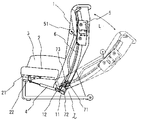
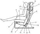
図1は本発明のマッサージ機の背凭れ部が起立した状態の一実施例を示す説明図であり、図2は本発明のマッサージ機の背凭れ部が倒伏した状態の一実施例を示す説明図であり、図3は本発明のマッサージ機における背凭れ部の起伏による当接位置のずれ寸法を表す説明図であり、図4及び図5は本発明のマッサージ機の使用状態を示す説明図であり、図6乃至図8は本発明のマッサージ機におけるマッサージ機構の昇降補正用ブロック回路図である。
【0017】
本発明に使用される実施例の椅子は、座部2と該座部2に対し傾斜角度調整自在に取り付けられた背凭れ部1と、該座部2の左右両側に立設された肘掛部3とで構成している。
【0018】
また、座部2に対する背凭れ部1の取り付け手段としては、各図に示す如く、背凭れ部1のフレーム11下部に揺動板12を枢着し、座部2の下部側フレーム21に垂下板22を枢止して、これら揺動板12及び垂下板22間に油圧シリンダや電動アクチュエータ等の傾倒調整部材4を枢支連結して構成している。
【0019】
よって、座部2の肘掛部3外側方に備えたリクライニング操作レバー(図示せず)で前記傾倒調整部材4を作動させると、図1及び図4に示す起立状態から図2及び図5に示すような倒伏状態に背凭れ部1を任意の傾斜角度に変えることができるのである。
【0020】
而して、本発明のマッサージ機は、施療者背部を施療し得る上記椅子等の背部位置である背凭れ部1に、施療子51を備え、該施療子51で揉みマッサージや叩きマッサージ及びローリングマッサージや指圧マッサージ等のマッサージを行い得るマッサージ機構5が内装されており、該マッサージ機構5は、背凭れ部1の高さ方向全域に配設されたレール6に沿って昇降移動自在に設けられている。
【0021】
実施例では、前記レール6の下部側に、該レール6全体を昇降補正して保持し得る昇降補正機構7を設けたものを例示しており、該昇降補正機構7は、背凭れ部2下部に固設された駆動モータ72と、該駆動モータ72に接続されて回転自在な螺軸73と、前記レール6を下部側で保持すると共に該螺軸73に噛合して昇降し得るレール保持板71とで構成している。
【0022】
以下に本発明のマッサージ機のブロック回路図に基づいて説明する。図6は、本発明のマッサージ機におけるマッサージ機構の昇降補正用ブロック回路図の一実施例を示すものであり、本発明の起伏可能な背凭れ部1内に昇降自在なマッサージ機構5を内装したマッサージ機の、マッサージ機構5の施療子51と施療者背部との起立状態での当接位置L1(図4参照)と、施療子51と施療者背部との倒伏状態での当接位置L2(図5参照)とを当接位置検知回路で検知し、これを認識回路で認識させるようにしており、この認識結果に基づいてその当接位置差L2−L1(L)を演算回路で演算算出して、前記マッサージ機構5の昇降補正回路に転送される。
【0023】
そして、前記昇降補正回路に送り込まれた補正データは、昇降駆動回路に送出され、該駆動回路の指示に基づき、昇降補正機構7の駆動モータ72を作動させて、背凭れ部1の起伏に応じて当接位置差L2−L1(L)範囲内を昇降移動させるようにするのである。
【0024】
また、図6のブロック回路図は、背凭れ部1の起伏角度に応じてマッサージ機構5を昇降補正できるものであり、本発明の起伏可能な背凭れ部1内に昇降自在なマッサージ機構5を内装したマッサージ機の、マッサージ機構5の施療子51と施療者背部との起立状態での当接位置L1(図4参照)と、施療子51と施療者背部との倒伏状態での当接位置L2(図5参照)とを当接位置検知回路で検知し、これを認識回路で認識させると共にこの認識結果に基づいて演算回路でその当接位置差L2−L1(L)を起伏角度差で除算して、前記マッサージ機構5の昇降補正回路に転送される。
【0025】
そして、前記昇降補正回路に送り込まれた背凭れ部1の起伏角度に応じた補正データは昇降駆動回路に送出され、該駆動回路の指示に基づき、昇降補正機構7の駆動モータ72を作動させて、背凭れ部1の起伏角度に応じた当接位置差L2−L1(L)範囲内を昇降移動させるようにするのである。
【0026】
更に、図7のブロック回路図は、背凭れ部1の肩位置に適応させてマッサージ機構5を昇降補正できるものであり、本発明の起伏可能な背凭れ部1内に昇降自在なマッサージ機構5を内装したマッサージ機の、マッサージ機構5の施療子51と施療者背部の肩位置との起立状態での当接位置L1(図4参照)と、施療子51と施療者背部の肩位置との倒伏状態での当接位置L2(図5参照)とを肩位置検知回路で検知し、これを認識回路で認識させると共に、この認識結果に基づいて演算回路でその当接位置差L2−L1を演算するか若しくは該差L2−L1(L)を起伏角度差で除算して、前記マッサージ機構5の昇降補正回路に転送される。
【0027】
そして、前記昇降補正回路に送り込まれた背凭れ部1の起伏角度に応じた補正データは昇降駆動回路に送出され、該駆動回路の指示に基づき、昇降補正機構7の駆動モータ72を作動させて、背凭れ部1の起伏角度に応じた当接位置差L2−L1(L)範囲内を昇降移動させるようにするのである。
【0028】
更にまた、図8のブロック回路図は、本発明のマッサージ機におけるマッサージ機構の昇降補正用ブロック回路図の一実施例を示すものであり、背凭れ部1の肩位置に適応させてマッサージ機構5を制御しながら昇降補正できるものであり、本発明の起伏可能な背凭れ部1内に昇降自在なマッサージ機構5を内装したマッサージ機の、マッサージ機構5の施療子51と施療者背部の肩位置との起立状態での当接位置L1(図4参照)と、施療子51と施療者背部の肩位置との倒伏状態での当接位置L2(図5参照)とを肩位置検知回路及び当接位置回路で全体の当接位置と肩位置とを検知し、これを認識回路で認識させると共に、この認識結果に基づいて演算回路でその当接位置差L2−L1(又は肩位置差L2−L1)を演算するか若しくは該差L2−L1(L)を起伏角度差で除算して、前記マッサージ機構5を制御するよう昇降補正回路に転送される。
【0029】
そして、前記昇降補正回路に送り込まれた背凭れ部1の起伏角度に応じた補正データはその昇降範囲を昇降駆動回路に送出され、該駆動回路の指示に基づき昇降補正機構7の駆動モータ72を作動させて、背凭れ部1の起伏角度に応じた当接位置差L2−L1(L)範囲内を昇降移動させるようにするのである。
【0030】
以上のように構成された本発明を使用するにあっては、施療者が座部2に着座して背凭れ部1に凭れた上で、電源スイッチを入れるだけで良く、背凭れ部1の施療子51との当接位置(または肩位置)を当接位置検知回路(または肩位置検知回路)で検知して、該検知結果を認識して演算回路で演算し、該演算結果に基づいて昇降補正機構7が自動的に稼動し、マッサージ機構5を自動昇降補正する事ができる。
【0031】
また、施療者が背凭れ部1を起立状態から倒伏させた場合には、図3に示したように背凭れ部1の施療子51との当接位置(または肩位置)が変化する為、この変化した当接位置を当接位置検知回路(または肩位置検知回路)で検知して、その検知結果である当接位置差Lを演算回路で算出し、該演算結果に基づいて昇降補正機構7が自動的に稼動してマッサージ機構5の施療子51が同位置に当接するよう降動補正する事ができるのである。
【0032】
【発明の効果】
よって、本発明では、起伏可能な背凭れ部内に昇降自在なマッサージ機構を内装したマッサージ機のマッサージ機構と施療者背部との当接位置を検知手段で検知して、背凭れ部の起伏によるマッサージ機構と当接位置とのずれを適宜に昇降補正し得るよう構成している為、座高の異なる施療者の座高差により、その都度施療子当接位置を設定する必要のある従来のマッサージ機とは異なり、各施療者に応じて施療範囲を補正する事ができ、常時適切な位置で有効範囲の施療を行う事ができる。
【0033】
また、本発明のマッサージ機は、起伏可能な背凭れ部内に昇降自在なマッサージ機構を内装したマッサージ機のマッサージ機構と施療者背部との当接位置を検知して、該検知結果を背凭れ部の起伏角度の変化に応じて生じるマッサージ機構と当接位置とのずれを、適宜に昇降補正し得るよう構成している為、常時一定の施療範囲で施療子の上部位置が位置決め設定されてマッサージを行う従来のマッサージ機とは異なり、背凭れ部の起立状態と倒伏状態との施療者に対する施療位置のずれを逐次検知して補正し、常時適切な位置で施療を行う事ができる。
【0034】
更に、本発明のマッサージ機は、起伏可能な背凭れ部内に昇降自在なマッサージ機構を内装したマッサージ機のマッサージ機構と施療者背部の肩位置との当接位置を検知して、該検知結果に基づいて背凭れ部の起伏に応じてマッサージ機構を昇降補正し得るよう制御している為、常時一定の施療範囲で施療子の施療位置が位置決め設定されてマッサージを行う従来のマッサージ機とは異なり、常時施療者の肩位置にマッサージ機構を当接させるよう補正する事ができ、誤って頭部に打撃を与えるという心配も無く、常時有効施療範囲を安全に施療させる事ができる。
【図面の簡単な説明】
【図1】本発明のマッサージ機の背凭れ部が起立した状態の一実施例を示す説明図である。
【図2】本発明のマッサージ機の背凭れ部が倒伏した状態の一実施例を示す説明図である。
【図3】本発明のマッサージ機における背凭れ部の起伏による当接位置のずれ寸法を表す説明図である。
【図4】本発明のマッサージ機の使用状態を示す説明図である。
【図5】本発明のマッサージ機の使用状態を示す説明図である。
【図6】本発明のマッサージ機におけるマッサージ機構の昇降補正用ブロック回路図である。
【図7】本発明のマッサージ機におけるマッサージ機構の昇降補正用ブロック回路図である。
【図8】本発明のマッサージ機におけるマッサージ機構の昇降補正用ブロック回路図である。
【符号の説明】
1 背凭れ部
5 マッサージ機構
7 昇降補正機構
71 レール保持板
72 駆動モータ
73 螺軸
L1 背凭れ部が起立状態での施療子の当接位置
L2 背凭れ部が倒伏状態での施療子の当接位置
L 当接位置差(当接位置のずれ寸法)[0001]
[Industrial application fields]
The present invention relates to a massage machine that detects a treatment element position of a backrest in a massage machine body corresponding to a treatment position of a user according to the undulation of the backrest and can correct the treatment position in a timely manner. It is.
[0002]
[Prior art]
In this type of conventional massage machine, a massage mechanism is incorporated in the backrest portion of the chair body, and it is possible to arbitrarily perform massage massage, tapping massage, and rolling massage by the massage mechanism.
[0003]
However, with this kind of conventional massage machine, you can do any of the above massages, but when you move the backrest part of the chair body from the standing state to the lying state, or conversely from the lying state to the lying state Further, there is a shift in the position of the treatment element of the massage mechanism that comes into contact with the treatment part, and it is necessary for the user to adjust the treatment part in contact with the treatment element position.
[0004]
In addition, the same applies when multiple people in the home use a massage machine, because the position of the treatment element as described above differs depending on the treatment person to be used, so when treatment persons with different sitting heights perform treatment alternately. However, it was necessary to adjust the position of the treatment element each time.
[0005]
[Problems to be solved by the invention]
Therefore, there is a problem that the user cannot perform a relaxing massage because the user needs to adjust the position of the treatment element each time.
[0006]
The present invention has been made in view of the above circumstances, and sequentially detects and corrects the shift of the treatment position for the user between the standing state and the lying state of the backrest portion, and always performs treatment at an appropriate position. The purpose is to provide a massage machine that can do things.
[0007]
Another object of the present invention is to provide a massage machine that detects the undulation angle of the backrest, corrects the treatment position according to the detected angle, and can always perform treatment at an appropriate position. .
[0008]
It is another object of the present invention to provide a massage machine that can correct the treatment position by detecting the shoulder position of the user and correcting it based on the detection result.
[0009]
[Means for Solving the Problems]
The massage machine of the present invention is configured as follows in order to achieve the above-described objects. That is, the massage machine of the present invention is a massage machine in which a massage mechanism that can be moved up and down by driving a drive motor is provided in a backrest that can be raised and lowered, and the massage machine is brought into contact with the back of the user. Detection means capable of detecting the position is provided, and the detection means is a contact position L1 in the standing state of the treatment element of the massage mechanism and the back of the user, and a contact in a lying state of the treatment element and the back of the user The position L2 is detected by the contact position detection circuit, recognized by the recognition circuit, the detection result is recognized, and the contact position difference L2-L1 (L) is calculated by the arithmetic circuit based on the recognition result. By dividing by the undulation angle difference, based on the calculation result, the drive motor is operated and the massage mechanism is moved up and down within the range of the contact position difference L2-L1 (L) . Undulating It is characterized in that configured the deviation of the contact position can lift correction with massaging mechanism that.
[0012]
[Action]
The massage machine of this invention brings about the following effects by comprising as mentioned above.
[0013]
That is , according to the present invention, the contact position between the massaging mechanism of the massaging machine and the back of the user who are able to move up and down in the backrest that can be raised and lowered is detected by the detecting means, and the massaging mechanism is raised and lowered to an appropriate position. Since it is configured so that it can be corrected, when a user with a different sitting height is seated and used, the treatment range can be corrected according to each user, and the effective range can be treated at an appropriate position at all times. .
[0014]
In addition , the massage machine of the present invention detects the contact position between the massage mechanism of the massage machine and the user's back that has a massage mechanism that can be moved up and down inside the backrest that can be raised and lowered, and the detection result is displayed on the backrest. Since the massage mechanism can be adjusted up and down appropriately according to the change in the undulation angle, the shift of the treatment position with respect to the user between the standing state and the lying state of the backrest part is sequentially detected and corrected. , Treatment can always be performed at an appropriate position.
[0015]
Furthermore , the massage machine of the present invention detects the contact position between the massage mechanism of the massage machine equipped with a freely elevating massage mechanism in the undulating backrest and the shoulder position of the back of the user, and the detection result Since the massage mechanism is controlled so that it can be lifted up and down based on it, it can be corrected so that the massage mechanism is always in contact with the shoulder position of the user, and there is no risk of hitting the head accidentally, and it is effective The treatment range can be treated safely.
[0016]
BEST MODE FOR CARRYING OUT THE INVENTION
Hereinafter, the massage machine of the present invention will be described in detail based on an embodiment shown in the drawings.
FIG. 1 is an explanatory view showing an embodiment of a state where the backrest portion of the massage machine of the present invention stands up, and FIG. 2 is an explanatory view showing an embodiment of the state where the backrest portion of the massage machine of the present invention is lying down. FIG. 3 is an explanatory view showing the displacement size of the contact position due to the undulation of the backrest portion in the massage machine of the present invention, and FIGS. 4 and 5 are explanatory views showing the use state of the massage machine of the present invention FIGS. 6 to 8 are block circuit diagrams for elevation correction of the massage mechanism in the massage machine of the present invention.
[0017]
The chair of the embodiment used in the present invention includes a
[0018]
Further, as shown in each drawing, the
[0019]
Therefore, when the
[0020]
Thus, the massage machine of the present invention includes the
[0021]
In the embodiment, an example in which an elevation correction mechanism 7 capable of correcting and holding the
[0022]
Below, it demonstrates based on the block circuit diagram of the massage machine of this invention. FIG. 6 shows an embodiment of a block circuit diagram for raising / lowering correction of the massage mechanism in the massage machine of the present invention, and a freely elevating
[0023]
Then, the correction data sent to the elevation correction circuit is sent to the elevation drive circuit, and the
[0024]
The block circuit diagram of Figure 6, which can lift
[0025]
The correction data corresponding to the undulation angle of the
[0026]
Further, the block circuit diagram of FIG. 7 is one in which the
[0027]
The correction data corresponding to the undulation angle of the
[0028]
Furthermore, the block circuit diagram of FIG. 8 shows an embodiment of a block circuit diagram for elevation correction of the massage mechanism in the massage machine according to the present invention. The
[0029]
Then, the correction data corresponding to the undulation angle of the
[0030]
In order to use the present invention configured as described above, the user only needs to turn on the power switch after the user sits on the
[0031]
Further, when the user lays the
[0032]
【The invention's effect】
Therefore , in the present invention, the position of contact between the massage mechanism of the massage machine and the user's back, which includes a massage mechanism that can be raised and lowered, is detected by the detection means, and the massage by the undulation of the backrest is detected. Because it is configured so that the deviation between the mechanism and the contact position can be corrected appropriately, the conventional massage machine that needs to set the treatment element contact position each time due to the difference in seat height between the users with different seat heights In contrast, the treatment range can be corrected according to each user, and the treatment of the effective range can be performed at an appropriate position at all times.
[0033]
In addition , the massage machine of the present invention detects the contact position between the massage mechanism of the massage machine and the user's back that has a massage mechanism that can be moved up and down inside the backrest that can be raised and lowered, and the detection result is displayed on the backrest. Since the displacement between the massage mechanism and the abutment position that occurs according to the change in the undulation angle can be corrected up and down appropriately, the upper position of the treatment element is always positioned and set within a certain treatment range. Unlike conventional massage machines that perform the treatment, it is possible to sequentially detect and correct the shift of the treatment position with respect to the user between the standing state and the lying state of the backrest and perform treatment at an appropriate position at all times.
[0034]
Furthermore , the massage machine of the present invention detects the contact position between the massage mechanism of the massage machine equipped with a freely elevating massage mechanism in the undulating backrest and the shoulder position of the back of the user, and the detection result Based on the undulation of the backrest, the massage mechanism is controlled so that it can be lifted and lowered, so it is different from conventional massage machines that perform massage with the treatment position of the treatment element always positioned and set within a certain treatment range. The massaging mechanism can be corrected so as to contact the shoulder position of the always-treated person, and there is no fear of hitting the head accidentally, so that the always effective treatment range can be treated safely.
[Brief description of the drawings]
FIG. 1 is an explanatory view showing an embodiment of a state where a backrest portion of a massage machine according to the present invention stands upright.
FIG. 2 is an explanatory view showing an embodiment of a state where the backrest of the massage machine of the present invention is lying down.
FIG. 3 is an explanatory diagram showing a displacement dimension of a contact position due to undulation of a backrest portion in the massage machine of the present invention.
FIG. 4 is an explanatory view showing a usage state of the massage machine of the present invention.
FIG. 5 is an explanatory view showing a usage state of the massage machine of the present invention.
FIG. 6 is a block circuit diagram for elevation correction of the massage mechanism in the massage machine of the present invention.
FIG. 7 is a block circuit diagram for elevation correction of the massage mechanism in the massage machine of the present invention.
FIG. 8 is a block circuit diagram for elevation correction of the massage mechanism in the massage machine of the present invention.
[Explanation of symbols]
DESCRIPTION OF
Claims (1)
当該検知手段は、マッサージ機構の施療子と施療者背部との起立状態での当接位置L1と、施療子と施療者背部との倒伏状態での当接位置L2とを当接位置検知回路で検知し、これを認識回路で認識し、
該検知結果を認識して、この認識結果に基づいて演算回路でその当接位置差L2−L1(L)を起伏角度差で除算し、該演算結果に基づいて、前記駆動モータを作動させて前記当接位置差L2−L1(L)範囲内で前記マッサージ機構を昇降移動させることにより、前記背凭れ部の起伏によるマッサージ機構との当接位置のずれを昇降補正し得るよう構成する事を特徴とするマッサージ機。In a massage machine equipped with a massage mechanism that can be moved up and down by driving a drive motor in a backrest that can be raised and lowered, the massage machine is provided with detection means that can detect the contact position between the massage mechanism and the back of the user ,
The detection means uses a contact position detection circuit to determine a contact position L1 in a standing state between the treatment element of the massage mechanism and the back of the user and a contact position L2 in a lying state of the treatment element and the back of the user. Detect it, recognize it with a recognition circuit,
Recognizing the detection result, based on the recognition result, the arithmetic circuit divides the contact position difference L2-L1 (L) by the undulation angle difference, and based on the calculation result, operates the drive motor. By moving the massage mechanism up and down within the range of the contact position difference L2−L1 (L) , the shift of the contact position with the massage mechanism due to the undulation of the backrest can be corrected up and down. Characteristic massage machine.
Priority Applications (1)
| Application Number | Priority Date | Filing Date | Title |
|---|---|---|---|
| JP2000260272A JP4809969B2 (en) | 2000-08-30 | 2000-08-30 | Massage machine |
Applications Claiming Priority (1)
| Application Number | Priority Date | Filing Date | Title |
|---|---|---|---|
| JP2000260272A JP4809969B2 (en) | 2000-08-30 | 2000-08-30 | Massage machine |
Publications (2)
| Publication Number | Publication Date |
|---|---|
| JP2002065788A JP2002065788A (en) | 2002-03-05 |
| JP4809969B2 true JP4809969B2 (en) | 2011-11-09 |
Family
ID=18748310
Family Applications (1)
| Application Number | Title | Priority Date | Filing Date |
|---|---|---|---|
| JP2000260272A Expired - Fee Related JP4809969B2 (en) | 2000-08-30 | 2000-08-30 | Massage machine |
Country Status (1)
| Country | Link |
|---|---|
| JP (1) | JP4809969B2 (en) |
Cited By (2)
| Publication number | Priority date | Publication date | Assignee | Title |
|---|---|---|---|---|
| KR20170013795A (en) * | 2015-07-28 | 2017-02-07 | 코웨이 주식회사 | Method for controlling the massage ball assembly in a massage chair automatically and the massage chair using the same |
| KR20170127775A (en) * | 2016-05-12 | 2017-11-22 | 코웨이 주식회사 | Method for operating a relax stretching mode in a massage chair using progressive muscular relaxation and the massage chair capable of using the same |
Families Citing this family (2)
| Publication number | Priority date | Publication date | Assignee | Title |
|---|---|---|---|---|
| DE102005061363A1 (en) * | 2005-12-21 | 2007-07-05 | Alexander Von Gencsy | Person e.g. children, rescue device for use in multi-story building, has hydraulic brake mechanism arranged between hub body and outer body, where person retainer is fixed at holding unit by carrier cloth |
| CN107582319B (en) * | 2017-09-28 | 2020-06-19 | 北京联合大学 | Intelligent massage equipment |
Family Cites Families (8)
| Publication number | Priority date | Publication date | Assignee | Title |
|---|---|---|---|---|
| JPS59200648A (en) * | 1983-04-28 | 1984-11-14 | 松下電工株式会社 | Treating machine |
| JP3069361B2 (en) * | 1990-02-23 | 2000-07-24 | 松下電工株式会社 | Massage chair |
| JP3133397B2 (en) * | 1991-08-01 | 2001-02-05 | 三洋電機株式会社 | Massage machine |
| JPH1099401A (en) * | 1996-10-01 | 1998-04-21 | Marutaka:Kk | Seat with massage function |
| JPH1119150A (en) * | 1997-07-07 | 1999-01-26 | Sanyo Electric Co Ltd | Massage machine |
| JPH11123221A (en) * | 1997-10-23 | 1999-05-11 | Marutaka Co Ltd | Seat having massage function |
| JPH11123218A (en) * | 1997-10-23 | 1999-05-11 | Marutaka Co Ltd | Seat provided with massage function |
| JP2001252319A (en) * | 2000-03-10 | 2001-09-18 | Marutaka Co Ltd | Motor-driven massager |
-
2000
- 2000-08-30 JP JP2000260272A patent/JP4809969B2/en not_active Expired - Fee Related
Cited By (4)
| Publication number | Priority date | Publication date | Assignee | Title |
|---|---|---|---|---|
| KR20170013795A (en) * | 2015-07-28 | 2017-02-07 | 코웨이 주식회사 | Method for controlling the massage ball assembly in a massage chair automatically and the massage chair using the same |
| KR102537566B1 (en) * | 2015-07-28 | 2023-06-01 | 코웨이 주식회사 | Method for controlling the massage ball assembly in a massage chair automatically and the massage chair using the same |
| KR20170127775A (en) * | 2016-05-12 | 2017-11-22 | 코웨이 주식회사 | Method for operating a relax stretching mode in a massage chair using progressive muscular relaxation and the massage chair capable of using the same |
| KR102630784B1 (en) * | 2016-05-12 | 2024-01-29 | 코웨이 주식회사 | Method for operating a relax stretching mode in a massage chair using progressive muscular relaxation and the massage chair capable of using the same |
Also Published As
| Publication number | Publication date |
|---|---|
| JP2002065788A (en) | 2002-03-05 |
Similar Documents
| Publication | Publication Date | Title |
|---|---|---|
| JP4416019B2 (en) | Massage machine | |
| CN113908035B (en) | Massaging machine | |
| TWI331915B (en) | ||
| KR102209833B1 (en) | MOBILE and TRANSFERRING ROBOT FOR HANDICAPED PERSON | |
| JP7453685B2 (en) | chair massage machine | |
| KR20160055642A (en) | Mattress assembly having an apparatus for controlling pressure of mattress | |
| JP4809969B2 (en) | Massage machine | |
| JP6739296B2 (en) | Massage machine | |
| JP3588129B2 (en) | Massage machine | |
| JP3956653B2 (en) | Massage machine | |
| JP2005066053A (en) | Bedding for sound sleep | |
| CN110769796B (en) | Massaging machine | |
| JP4636749B2 (en) | Chair type massage machine | |
| JP4903000B2 (en) | Stand-up support device | |
| JP2007527303A (en) | The surface that forms the contour of the body | |
| JP7161741B2 (en) | Massage machine | |
| JP4240585B2 (en) | Massage chair with seat lift | |
| JP4483547B2 (en) | Massage machine | |
| JP7282418B2 (en) | Massage machine | |
| JP4174125B2 (en) | Chair type massage structure | |
| JP4875969B2 (en) | Massage machine | |
| KR102549833B1 (en) | 2-Stage Elevating and Lowering Joint Type Electric Left Side Aid Device | |
| CA3229548A1 (en) | A bed for turning patients | |
| JPH0520664U (en) | Floor rub prevention bed | |
| JP2009028089A (en) | Massage machine |
Legal Events
| Date | Code | Title | Description |
|---|---|---|---|
| A521 | Written amendment |
Free format text: JAPANESE INTERMEDIATE CODE: A821 Effective date: 20000830 |
|
| A621 | Written request for application examination |
Free format text: JAPANESE INTERMEDIATE CODE: A621 Effective date: 20070731 |
|
| RD02 | Notification of acceptance of power of attorney |
Free format text: JAPANESE INTERMEDIATE CODE: A7422 Effective date: 20070810 |
|
| A131 | Notification of reasons for refusal |
Free format text: JAPANESE INTERMEDIATE CODE: A131 Effective date: 20100720 |
|
| A521 | Written amendment |
Free format text: JAPANESE INTERMEDIATE CODE: A523 Effective date: 20100921 |
|
| RD02 | Notification of acceptance of power of attorney |
Free format text: JAPANESE INTERMEDIATE CODE: A7422 Effective date: 20100921 |
|
| A521 | Written amendment |
Free format text: JAPANESE INTERMEDIATE CODE: A523 Effective date: 20100921 |
|
| A131 | Notification of reasons for refusal |
Free format text: JAPANESE INTERMEDIATE CODE: A131 Effective date: 20110322 |
|
| A521 | Written amendment |
Free format text: JAPANESE INTERMEDIATE CODE: A523 Effective date: 20110520 |
|
| A521 | Written amendment |
Free format text: JAPANESE INTERMEDIATE CODE: A523 Effective date: 20110520 |
|
| TRDD | Decision of grant or rejection written | ||
| A01 | Written decision to grant a patent or to grant a registration (utility model) |
Free format text: JAPANESE INTERMEDIATE CODE: A01 Effective date: 20110802 |
|
| A01 | Written decision to grant a patent or to grant a registration (utility model) |
Free format text: JAPANESE INTERMEDIATE CODE: A01 |
|
| A61 | First payment of annual fees (during grant procedure) |
Free format text: JAPANESE INTERMEDIATE CODE: A61 Effective date: 20110822 |
|
| FPAY | Renewal fee payment (event date is renewal date of database) |
Free format text: PAYMENT UNTIL: 20140826 Year of fee payment: 3 |
|
| R150 | Certificate of patent or registration of utility model |
Ref document number: 4809969 Country of ref document: JP Free format text: JAPANESE INTERMEDIATE CODE: R150 Free format text: JAPANESE INTERMEDIATE CODE: R150 |
|
| R250 | Receipt of annual fees |
Free format text: JAPANESE INTERMEDIATE CODE: R250 |
|
| R250 | Receipt of annual fees |
Free format text: JAPANESE INTERMEDIATE CODE: R250 |
|
| R250 | Receipt of annual fees |
Free format text: JAPANESE INTERMEDIATE CODE: R250 |
|
| R250 | Receipt of annual fees |
Free format text: JAPANESE INTERMEDIATE CODE: R250 |
|
| R250 | Receipt of annual fees |
Free format text: JAPANESE INTERMEDIATE CODE: R250 |
|
| R250 | Receipt of annual fees |
Free format text: JAPANESE INTERMEDIATE CODE: R250 |
|
| LAPS | Cancellation because of no payment of annual fees |