JP4809560B2 - Re-accessible medical needle safety device - Google Patents
Re-accessible medical needle safety device Download PDFInfo
- Publication number
- JP4809560B2 JP4809560B2 JP2001534447A JP2001534447A JP4809560B2 JP 4809560 B2 JP4809560 B2 JP 4809560B2 JP 2001534447 A JP2001534447 A JP 2001534447A JP 2001534447 A JP2001534447 A JP 2001534447A JP 4809560 B2 JP4809560 B2 JP 4809560B2
- Authority
- JP
- Japan
- Prior art keywords
- needle
- shield
- tip
- medical
- segment
- Prior art date
- Legal status (The legal status is an assumption and is not a legal conclusion. Google has not performed a legal analysis and makes no representation as to the accuracy of the status listed.)
- Expired - Fee Related
Links
- 238000000034 method Methods 0.000 description 29
- 230000001681 protective effect Effects 0.000 description 17
- 238000006073 displacement reaction Methods 0.000 description 11
- 238000002347 injection Methods 0.000 description 10
- 239000007924 injection Substances 0.000 description 10
- 239000004743 Polypropylene Substances 0.000 description 9
- -1 polypropylene Polymers 0.000 description 9
- 229920001155 polypropylene Polymers 0.000 description 9
- 238000007920 subcutaneous administration Methods 0.000 description 7
- 230000008878 coupling Effects 0.000 description 6
- 238000010168 coupling process Methods 0.000 description 6
- 238000005859 coupling reaction Methods 0.000 description 6
- 238000001990 intravenous administration Methods 0.000 description 6
- 239000012528 membrane Substances 0.000 description 6
- 238000005070 sampling Methods 0.000 description 6
- 239000003814 drug Substances 0.000 description 5
- 239000000463 material Substances 0.000 description 5
- 210000002105 tongue Anatomy 0.000 description 5
- 210000003954 umbilical cord Anatomy 0.000 description 5
- 239000008280 blood Substances 0.000 description 4
- 210000004369 blood Anatomy 0.000 description 4
- 239000007788 liquid Substances 0.000 description 4
- 230000001012 protector Effects 0.000 description 4
- 206010069803 Injury associated with device Diseases 0.000 description 3
- 206010052428 Wound Diseases 0.000 description 3
- 208000027418 Wounds and injury Diseases 0.000 description 3
- 230000009471 action Effects 0.000 description 3
- 229940079593 drug Drugs 0.000 description 3
- 239000004033 plastic Substances 0.000 description 3
- 208000012266 Needlestick injury Diseases 0.000 description 2
- 238000005452 bending Methods 0.000 description 2
- 238000013461 design Methods 0.000 description 2
- 239000013013 elastic material Substances 0.000 description 2
- 238000004146 energy storage Methods 0.000 description 2
- 230000012953 feeding on blood of other organism Effects 0.000 description 2
- 238000001746 injection moulding Methods 0.000 description 2
- 238000003780 insertion Methods 0.000 description 2
- 230000037431 insertion Effects 0.000 description 2
- 230000003993 interaction Effects 0.000 description 2
- 238000004519 manufacturing process Methods 0.000 description 2
- 230000008569 process Effects 0.000 description 2
- 230000000630 rising effect Effects 0.000 description 2
- 238000012546 transfer Methods 0.000 description 2
- 208000030507 AIDS Diseases 0.000 description 1
- 208000035049 Blood-Borne Infections Diseases 0.000 description 1
- 230000003213 activating effect Effects 0.000 description 1
- 239000000853 adhesive Substances 0.000 description 1
- 230000001070 adhesive effect Effects 0.000 description 1
- 238000004458 analytical method Methods 0.000 description 1
- 230000000845 anti-microbial effect Effects 0.000 description 1
- 239000004599 antimicrobial Substances 0.000 description 1
- 230000008901 benefit Effects 0.000 description 1
- 238000009640 blood culture Methods 0.000 description 1
- 230000003749 cleanliness Effects 0.000 description 1
- 238000004891 communication Methods 0.000 description 1
- 238000011109 contamination Methods 0.000 description 1
- 230000006378 damage Effects 0.000 description 1
- 238000011161 development Methods 0.000 description 1
- 238000005516 engineering process Methods 0.000 description 1
- 239000012530 fluid Substances 0.000 description 1
- 230000036541 health Effects 0.000 description 1
- 208000006454 hepatitis Diseases 0.000 description 1
- 231100000283 hepatitis Toxicity 0.000 description 1
- 230000036512 infertility Effects 0.000 description 1
- 238000010255 intramuscular injection Methods 0.000 description 1
- 239000007927 intramuscular injection Substances 0.000 description 1
- 230000002427 irreversible effect Effects 0.000 description 1
- 230000007246 mechanism Effects 0.000 description 1
- 230000003340 mental effect Effects 0.000 description 1
- 239000002184 metal Substances 0.000 description 1
- 230000003449 preventive effect Effects 0.000 description 1
- 230000003252 repetitive effect Effects 0.000 description 1
- 229920005989 resin Polymers 0.000 description 1
- 239000011347 resin Substances 0.000 description 1
- 230000035945 sensitivity Effects 0.000 description 1
- 230000035939 shock Effects 0.000 description 1
- 239000000243 solution Substances 0.000 description 1
- 238000010561 standard procedure Methods 0.000 description 1
- 238000011272 standard treatment Methods 0.000 description 1
- 229920003002 synthetic resin Polymers 0.000 description 1
- 239000000057 synthetic resin Substances 0.000 description 1
Images


Classifications
-
- A—HUMAN NECESSITIES
- A61—MEDICAL OR VETERINARY SCIENCE; HYGIENE
- A61M—DEVICES FOR INTRODUCING MEDIA INTO, OR ONTO, THE BODY; DEVICES FOR TRANSDUCING BODY MEDIA OR FOR TAKING MEDIA FROM THE BODY; DEVICES FOR PRODUCING OR ENDING SLEEP OR STUPOR
- A61M5/00—Devices for bringing media into the body in a subcutaneous, intra-vascular or intramuscular way; Accessories therefor, e.g. filling or cleaning devices, arm-rests
- A61M5/178—Syringes
- A61M5/1782—Devices aiding filling of syringes in situ
-
- A—HUMAN NECESSITIES
- A61—MEDICAL OR VETERINARY SCIENCE; HYGIENE
- A61M—DEVICES FOR INTRODUCING MEDIA INTO, OR ONTO, THE BODY; DEVICES FOR TRANSDUCING BODY MEDIA OR FOR TAKING MEDIA FROM THE BODY; DEVICES FOR PRODUCING OR ENDING SLEEP OR STUPOR
- A61M5/00—Devices for bringing media into the body in a subcutaneous, intra-vascular or intramuscular way; Accessories therefor, e.g. filling or cleaning devices, arm-rests
- A61M5/178—Syringes
- A61M5/31—Details
- A61M5/32—Needles; Details of needles pertaining to their connection with syringe or hub; Accessories for bringing the needle into, or holding the needle on, the body; Devices for protection of needles
- A61M5/3205—Apparatus for removing or disposing of used needles or syringes, e.g. containers; Means for protection against accidental injuries from used needles
- A61M5/321—Means for protection against accidental injuries by used needles
- A61M5/3243—Means for protection against accidental injuries by used needles being axially-extensible, e.g. protective sleeves coaxially slidable on the syringe barrel
- A61M5/3275—Means for protection against accidental injuries by used needles being axially-extensible, e.g. protective sleeves coaxially slidable on the syringe barrel being connected to the needle hub or syringe by radially deflectable members, e.g. longitudinal slats, cords or bands
-
- A—HUMAN NECESSITIES
- A61—MEDICAL OR VETERINARY SCIENCE; HYGIENE
- A61J—CONTAINERS SPECIALLY ADAPTED FOR MEDICAL OR PHARMACEUTICAL PURPOSES; DEVICES OR METHODS SPECIALLY ADAPTED FOR BRINGING PHARMACEUTICAL PRODUCTS INTO PARTICULAR PHYSICAL OR ADMINISTERING FORMS; DEVICES FOR ADMINISTERING FOOD OR MEDICINES ORALLY; BABY COMFORTERS; DEVICES FOR RECEIVING SPITTLE
- A61J1/00—Containers specially adapted for medical or pharmaceutical purposes
- A61J1/14—Details; Accessories therefor
- A61J1/20—Arrangements for transferring or mixing fluids, e.g. from vial to syringe
- A61J1/2003—Accessories used in combination with means for transfer or mixing of fluids, e.g. for activating fluid flow, separating fluids, filtering fluid or venting
- A61J1/2006—Piercing means
- A61J1/201—Piercing means having one piercing end
-
- A—HUMAN NECESSITIES
- A61—MEDICAL OR VETERINARY SCIENCE; HYGIENE
- A61J—CONTAINERS SPECIALLY ADAPTED FOR MEDICAL OR PHARMACEUTICAL PURPOSES; DEVICES OR METHODS SPECIALLY ADAPTED FOR BRINGING PHARMACEUTICAL PRODUCTS INTO PARTICULAR PHYSICAL OR ADMINISTERING FORMS; DEVICES FOR ADMINISTERING FOOD OR MEDICINES ORALLY; BABY COMFORTERS; DEVICES FOR RECEIVING SPITTLE
- A61J1/00—Containers specially adapted for medical or pharmaceutical purposes
- A61J1/14—Details; Accessories therefor
- A61J1/20—Arrangements for transferring or mixing fluids, e.g. from vial to syringe
- A61J1/2003—Accessories used in combination with means for transfer or mixing of fluids, e.g. for activating fluid flow, separating fluids, filtering fluid or venting
- A61J1/2048—Connecting means
- A61J1/2055—Connecting means having gripping means
-
- A—HUMAN NECESSITIES
- A61—MEDICAL OR VETERINARY SCIENCE; HYGIENE
- A61J—CONTAINERS SPECIALLY ADAPTED FOR MEDICAL OR PHARMACEUTICAL PURPOSES; DEVICES OR METHODS SPECIALLY ADAPTED FOR BRINGING PHARMACEUTICAL PRODUCTS INTO PARTICULAR PHYSICAL OR ADMINISTERING FORMS; DEVICES FOR ADMINISTERING FOOD OR MEDICINES ORALLY; BABY COMFORTERS; DEVICES FOR RECEIVING SPITTLE
- A61J1/00—Containers specially adapted for medical or pharmaceutical purposes
- A61J1/14—Details; Accessories therefor
- A61J1/20—Arrangements for transferring or mixing fluids, e.g. from vial to syringe
- A61J1/2096—Combination of a vial and a syringe for transferring or mixing their contents
-
- Y—GENERAL TAGGING OF NEW TECHNOLOGICAL DEVELOPMENTS; GENERAL TAGGING OF CROSS-SECTIONAL TECHNOLOGIES SPANNING OVER SEVERAL SECTIONS OF THE IPC; TECHNICAL SUBJECTS COVERED BY FORMER USPC CROSS-REFERENCE ART COLLECTIONS [XRACs] AND DIGESTS
- Y10—TECHNICAL SUBJECTS COVERED BY FORMER USPC
- Y10S—TECHNICAL SUBJECTS COVERED BY FORMER USPC CROSS-REFERENCE ART COLLECTIONS [XRACs] AND DIGESTS
- Y10S128/00—Surgery
- Y10S128/917—Body fluid, devices for protection therefrom, e.g. aids, hepatitus
- Y10S128/919—Syringe, means to protect user
Landscapes
- Health & Medical Sciences (AREA)
- Engineering & Computer Science (AREA)
- Hematology (AREA)
- Anesthesiology (AREA)
- Biomedical Technology (AREA)
- Heart & Thoracic Surgery (AREA)
- Vascular Medicine (AREA)
- Life Sciences & Earth Sciences (AREA)
- Animal Behavior & Ethology (AREA)
- General Health & Medical Sciences (AREA)
- Public Health (AREA)
- Veterinary Medicine (AREA)
- Environmental & Geological Engineering (AREA)
- Infusion, Injection, And Reservoir Apparatuses (AREA)
Description
【0001】
【発明の分野】
本発明は、一般には中空の内腔医療針用安全装置、特に、鋭い針チップを安全に遮蔽するために保護針シールドまたは保護針鞘を用いたシリンジ針装置に関し、医療処置の前後に使用される。より特定すれば、本発明は取外し可能な医療針シールド、鞘(シース)または囲いに関し、これは取外し可能で且つ再配置可能な保護用の針カバーとして使用され得るものである。本発明はまた、使用の際に針を更にシールドおよび保護するために使用することができ、また装置の鉢先端から付属の医療針シールドを選択的に外すために鍵をかけることができるコネクタまたはアダプタに関する。
【0002】
【発明の背景】
不注意に針で刺すことに付随する問題は、血液採取、医薬の経皮的注射、および医療針の使用を含む他の医療処置の技術において周知である。AIDS、肝炎および他の重篤な血液伝播性疾患への露出に対する現代人の敏感さのために、針で刺す問題にはより多くの注意が払われている。
【0003】
患者からの針の除去を含む処置は、通常、施術者が一方の手で針装置を除去しながら、他方の手で針が抜き取られる傷部位を押圧することを必要とする。付添いの施術者は、針の使い捨てに対するよりも傷のケアに対する注意を優先するのが普通である。通常の非安全装置の場合、このような優先度は、容易に手の届く範囲にある利用可能な鋭い容器の便利さ、または患者の側に残さずに安全に廃棄するためのもう一つの手段を必要とする。安全な処置とともに充分なケアを与えることは、患者の生理的状態および精神的状態(例えば、火傷単位および精神医学的に)によって複雑になることが多い。このような条件において、患者をケアしながら、使用済みの露出された針を適切に廃棄するために適切な行動を取ることは、不可能ではないにしても困難なことが多い。或る場所でシリンジに医薬を充填し、次いで針にキャップを被せないで患者の場所に運ぶ通常のプラクティスでは、偶然に針で突き刺す顕著な機械を与える。針を再度キャッピングすることは、再キャッピングに伴って偶然に針で刺す危険のために、現在のアメリカ合衆国の医療実務では認められていない。
【0004】
針のケアおよび廃棄の問題に関連した周知の知識および歴史は、偶然に針で突き刺すことを防止するための多くの装置をもたらしている。シリンジの針をシールドするための現在の装置は両手を必要とすることが多く、幾つかの装置では、針シールドの安全状態が容易には分からない。
【0005】
屡々、シリンジ針を複数回使用する必要がある。筋肉内注射を行うときは、薬瓶から内容物を抜取り、次いで内容物を患者に注射するのが通常のプラクティスである。薬瓶上の膜を穿刺し、次いで患者に注射するために、同じ針を使用するのが望ましい。しかし、薬瓶から内容物が抜き取られる場所が、患者に注射する場所から或る程度離れている場合がある。このような状況では、患者へ運ぶために施術者が針に再キャッピングすることがあり得る。同様に問題なのは、保護されていない針を運ぶもう一つのプラクティスである。幾つかの現在利用可能な安全装置は、針のカバーおよび再アクセスを可能にする。しかし、上記に開示したような因子が、これら安全装置の許容度を制限している。
【0006】
比較的安全な領域に針が侵入される状況(例えば、IVセットにおける「Y」コネクタを貫通する場合)でも、安全の必要性を認識することは、「無針システム」として共通に知られた種類の医療装置において、設計および販売に成功をもたらしている。しかし、これらのシステムでさえも、バイアル瓶を充填する手順は、シリンジを充填するために未だ鋭い針の使用を必要とするので、針の使用を完全に排除するものではない。シリンジが充填されたら、使用された針を除去して廃棄し、鈍いカニューレで置き換え、または、無針コネクタに接続する一方、シリンジ充填手順の際に針は露出され、危険なままであるのが普通の実務である。
【0007】
多数回使用のために再アクセス可能な針安全装置に対する、より満足な解決策を提供することが未だ必要とされている。
【0008】
【発明の概要】
簡単に要約すれば、ここに開示する新規な発明は、針挿入処置の終了時に医療針を患者から抜き取るとき針の先端が裸であるときに起きる、傷関連の針での突き刺しから生じる公知の重大な問題を劇的に減少させるものである。本発明は、医療処置における幾つかのステップにおいて医療針へのアクセスを可能にする一方、それらのステップの間では、安全なカバーで囲まれた状態に針を戻すことができるようにするものである。
【0009】
本発明では針保護シールドを用いるが、これは針の先端をカバーおよび保護するように移動可能であり、且つ医療処置を通して複数回使用するために、針および尖端を裸にするように移動させることができる。更に、当該針の先端はシールドによって保護的にカバーされることに加えて、該シールドには接触しない。
【0010】
本発明において、シールドは保護を与えるために針および先端の回りに配置される。解除可能な一時的ラッチが設けられるが、これはシールドを折り畳むために外すことができ、それによって、その後の医療処置のために針に再アクセスすることを可能にする。夫々の処置が完了したときに、該シールドは再度広げられ、ラッチされて、安全なカバーを提供する。また、使用の最後に確実な針チップ保護を補償する保護的シールドのために、選択的に活性化された解除不能なロックも設けられる。
【0011】
一実施例において、該シールドは、針のチップに対して近位方向に配置された針ガイドを含んでおり、これは、保護シールドを移動させて針をカバーおよびシールドするとき、およびシールドを除去して針を使用するために裸にするときに、シールドとの接触による損傷からチップを保護する。この針ガイドは、針の長軸に整列された状態で移動するように配置および拘束され、また、針チップと接触することなく、針の回りでのシールドの移動を容易にするように拘束される。
【0012】
一般に、当該装置は、一時的または解除可能であるが安定な、少なくとも二つの状態に構成することができる。一つの安定な状態において、当該シールドは、使用のために針が裸であるときに「邪魔にならない」で配置されるように拘束される。第二の解除可能な安定な状態において、当該シールドは、針および針チップの回りに保護的に配置されるように拘束される。更に、当該装置およびシールドは、組合された状態で、使用が完了したときに装置の更なる使用を妨げるように、確実且つ取外し不能に固定される永久的なロックを含んでいる。好ましくは、シールドを夫々の安定な状態に拘束するようにラッチが使用される。
【0013】
安全針装置における他の重要な因子には、装置が片手で効果的に使用され得ること、および、使用の間で針の安全な状態を維持しながら、針が多数回アクセスされ得ることが含まれる。特に、皮下シリンジ針装置の場合は、シリンジを予め充填するために、針を使用して医療用液体を収容したバイアル瓶にアクセスし、次いでその同じ針を使用して、シリンジの内容物を患者に供給するのが通常のプラクティスであるから、安全な状態から医療針に複数回アクセスできる能力は非常に重要である。
【0014】
本発明は、一般に、当該装置がシールドの安全な状態の方に動かされ、安全な状態から外され、または単純に安全な状態内で配置されるときに、不注意による針での傷害からユーザを保護しながら、また針およびその脆弱なチップを保護しながら、片手での操作、および医療針への複数回のアクセスを提供する。
【0015】
しかし、針シールドが有効であっても、例えば皮下適用で生じるように、針を裸にする標準的な処置で使用されるときに、針は不注意によって突き刺しを生じ易い。この理由で、無針システムが人気を得るようになった。本発明の一実施例は、連続的な保護カバー下に針を維持しながら針に対する機能的アクセスを提供するために、針シールドを特別のコネクタ(またはアダプタ)と組合せることを含んでいる。
【0016】
このような実施例において、夫々の展開されたシールドベースは遠位方向に配置されたラッチを有しており、該ラッチは不注意での折り畳みに対する防止策として、展開されたシールドを正しい位置にロックする。夫々のコネクタまたはアダプタは、アクチュエータおよび鍵を有している。これらによって、前記ラッチは、前記コネクタまたはアダプタを前記シールドに接続する動作によってロックが解除され、それにより、連続的保護カバーを針チップの回りに維持しながら、前記シールドを針から除去する(折り畳む)ことが可能になる。前記シールドが除去されるのと連携して、コネクタまたはアダプタの針尖端に向かう移動は、コネクタアダプタの方およびその中への線型経路(これは針の長軸と整列している)で行われる。この方法では、コネクタを使用する際に針が曲がる傾向は存在しない。針チップは、それがコネクタまたはアダプタ内に入るまで、シールドによって連続的に保護される。針チップが連続的にカバーされ保護されるので、シールドがコネクタまたはアダプタと共に使用される全ての目的について、針の安全性が保証される。
【0017】
このような目的は、一般には、コネクタまたはアダプタを使用しないで同じ機能を行うときに必要とされるのと同じ数および種類のステップによって満たされる。この理由のために、シールドと協働するこれらコネクタを使用する殆どの操作は、受動的操作と見なされる(即ち、それらは、シールドおよびコネクタのない標準的な処置のステップに追加するステップを必要としない)。受動的操作は、針がコネクタから引き抜かれるときに、シールドを伸展された針保護状態に自動的に戻すように働く、コネクタとびシールドとの間の相互作用によって更に実現される。シールドを接続および折り畳む場合と同様に、針がコネクタから抜き取られるときに、針チップは連続的にカバーされる。従って、シールドは、コネクタが外される前に針が完全に保護されることを保証し、それによって、針の使用前、針の使用の最中および針の使用後の安全を確実にする。
【0018】
本発明の範囲内において、このようなコネクタを安全かつ有効に用い得る多くの応用が存在する。例えば、これに限定されるものではないが、コネクタをバイアル瓶、静脈(IV)チューブセットおよび真空サンプリング管上に配置してもよい。
【0019】
手短に要約すると、上記の目的は、針の逐次的使用において針チップ保護シールドから医療針に繰返しアクセスするための医療針安全システムによって達成され、該安全システムは、細長い医療針および針ハブを含む医療針アセンブリーを備え、前記医療針は前記ハブに固定され、且つ遠位に配置された尖ったチップおよび前記ハブから前記チップへの線に沿って中間に配置される長い軸を有しており;前記ハブにヒンジ結合された安全シールドアセンブリーを備え、該安全シールドアセンブリーは、各セグメントが少なくとも一つの他のセグメントにヒンジ結合される複数の折り畳み可能なセグメントを含み、少なくとも一つの前記セグメントは前記針の長軸回りで旋回するように円弧状であり、前記シールドアセンブリーは更に、少なくとも一つの解除可能なラッチ部分を含み、該ラッチ部分は前記シールドが前記針の回りに伸張されたときにラッチして、前記針および針チップの回りに保護的に配置された針とは独立で且つ実質的に剛性の構造を与える目的で前記シールドを固定し、更にまた、それにより前記ラッチが解除されて、前記シールドが折り畳み可能に後退し、前記針および針チップが使用のために裸にされ、また後で針およびそのチップの回りに再伸張することを可能にするアクチュエータを含む。
【0020】
【発明の実施例の説明】
この説明において、「近位」という用語は、他に指定しない限り一般に、言及された事項について、当該装置の予想されるユーザに相対的に近い方を示すために用いられる。「遠位」という用語は、同様に、相対的に遠い方を示すために使用される。次に、図1〜図35に示した実施例を参照するが、これらの図では、全体を通して類似の部分を指定するために類似の番号を使用する。複数の部分が、類似ではあるが同一ではない形態および機能を有する場合には、解釈的な相互参照を容易にするためにプライムを付した数字が用いられる。
【0021】
本発明による針シールド安全装置の第一の実施例が、装置10として図1に示されている。装置10は、針カバー20および針ハブシールドアセンブリー30を有している。
【0022】
針ハブアセンブリー30は図2に更に良く示されており、ここではカバー20が除去されていて、医療針40を露出させ、さもなければ隠されている折り畳み可能な針シールド50の遠位部分を露出させて、それらが見えるようになっている。図1と図2との間の違いから明らかなように、針カバー20は細長い中空で円錐台形の遠位部分60を有しており、これは形状および機能において、使用前に針を保護するために通常使用される針カバーに類似している。また、カバー20は、横方向で近位に配置されたガード70を有している。ガード70は、針40を使用するためにカバー20を除去するよりも前の、不注意によるシールド50の駆動に対するキーパーとして作用する。現在入手可能な針カバーと同様に、針カバー20はポリプロピレン、他の合成樹脂材料、または、それらの均等物から形成すればよい(例えば、射出成形すればよい)。
【0023】
針40およびシールド50に加えて、アセンブリー30は針ハブ80を有しており、これには針40が固定され、またシールド50がヒンジ結合されている。この実施例では、ハブ80は雌型ルアー(ロック)フィッティング90を備えているのが見えるが、本発明の範囲内で他のフロースルーハブフィッティングおよび接合部を使用してもよい。針40は、一般には細長いシャンク92および尖ったチップ100を有するように形成される。
【0024】
医療針への再アクセスを許容する装置にとって、カバー20のようなカバーは必要でない可能性があることに留意するのが重要である。シールドが確実で且つ解除可能にラッチされるとき、アセンブリー30のような装置は、図5におけるシールド50のようなシールドによって針40が保護的にカバーされた、安全な状態に展開され得る。次いで、こうして展開された装置は、カバー20のようなカバーなしで、「バブルパック」のような抗菌性保護ラップの中に包装され、出荷される。このような展開およびカバーの排除は、基本的な装置のコストおよび廃棄する付属部品のコストの両方を低減する。
【0025】
この実施例の発明的な新規性の第一は、シールド50である。図4に示すように、シールド50は二つのセグメント、即ち、遠位セグメント110および近位セグメント120から形成される。三つ以上のセグメントを使用して、折り畳み可能な針シールドを形成してもよい。
【0026】
遠位セグメント110は、並列された一対の細長い側部片122および124、並びに閉じた端部126を有するように作製され、閉じた端部126が前記側部片122および124と連続して形成されることにより、中空の針チップ100のためのガード凹部128を形成する。シールド50が伸張されて、針40および針チップ100を保護するときに、チップ100は遠位セグメント110の如何なる部分とも接触しない。このような接触は、チップ100の構造的一体性を危険に曝し、従って針40の連続的な使用をも同様に危険に曝す。シールド50が伸張されて囲いになる場合、および折り畳まれて針チップ100を将来の使用のために裸にする場合の両方の場合に、針チップ100が遠位セグメント110の中へ、また該セグメントから外へ案内されることを保証するために、針ベアリングおよびガイド330が、夫々ヒンジ132および134によって側部部材122および124に取付けられる。針ベアリングおよびガイド330は、ヒンジ332を介して遠位セグメント110に対して回転し、閉鎖端326を針チップ100から遠くへ変位させる。図2および図7に最も良く見られるように、針ベアリングおよびガイド330は針ベアリング表面336を有しており、それによって針40は、遠位セグメント110が折り畳みおよび伸張の際に針40の回りを回転するときに、針チップ100が遠位シールド50に接触しないのを保証するように拘束される。
【0027】
遠位セグメント110は、近位に配置された一対の接続ヒンジ342および344(図2参照)を有しており、これによって、セグメント110はセグメント120にヒンジ結合される。アセンブリー30のヒンジの全部または一部は、ポリプロピレンまたはその均等物のような適切な材料が使用されるときには、成形ハブ80、近位セクション120および遠位セクション110の全部または何れかの部分の組み合わせを射出成形することによって、一体ヒンジとして形成すればよい。
【0028】
一対の横方向に伸びる翼部352および354が、セグメント110上で外側に且つ近位に配置されている(図2参照)。各翼部352および354は、夫々の側部322および324から遠くに変位されて(図4参照)、夫々362および364と番号を付した棚部を与え、これは解除可能なラッチのための受け止め部として働く。このような受け止め部およびラッチの組合せの動作は、以下で詳細に開示される。
【0029】
アセンブリー30の重要な要素は、図2、図4〜図6および図8に示した摺動可能なラッチ部370である。ラッチ部370は、近位セグメント120に摺動可能に取付けられ、またシールド50が可変かつ選択的に伸張されて針チップ100を保護するときに、セグメント110に対して解除可能および解除不能に接続するためのラッチを含んでいる。図2に示すように、ラッチ部370は二つのラッチ372および374を有しており、その夫々はラッチ部370の各側壁376および378に配置される。ラッチ374は、連結立上り部380、内側傾斜面382およびベアリング表面384を有する側壁378と一体に形成される。ラッチ372は、ラッチ374の並列されたミラーイメージ(鏡像)として形成される。ラッチ372の詳細は図示されていないが、その立上り部、内側傾斜面、およびベアリング表面は、ラッチ374の連結立上り部380、内側傾斜面382およびベアリング表面384と同様であり、この明細書では、380'、382'および384'の参照番号がそれぞれ付されている。傾斜表面382および382'が翼部352および354とそれぞれ合致するときの、立上り部380および380'の屈曲は、ラッチ部370が組立て工程でセグメント110上に「スナップ」されることを可能にする。
【0030】
次に、近位セグメント120の詳細な構造がより明瞭に示されている図7を参照する。ヒンジ342および344によって遠位セグメント110に接続されると共に、近位セグメント120はまた、一対のヒンジ386および388によって、針ハブ80に結合される。先に示したように、ヒンジ342、344、386および388のようなヒンジは、一体ヒンジとして成形すればよく、これは遠位セグメント110、近位セグメント120および/または針ハブ80の何れかの組合せが、一体の部分として成形されるべきである。このような場合に、部品はポリプロピレンまたはその均等物から成形すればよい。近位セグメント120は、好ましくは、平坦な頂部連結層390およびこれに直角に取付けられた二つの側部部材392および394を有する一体構造として形成される。夫々の側部部材は、層390から遠くに配置された、番号が夫々396および398の線形のレールを形成する。
【0031】
図8に最も良く見られるように、ラッチ部370は、一般にはラッチ部370の上部に配置された側に形成されたボタン部400を有している。夫々の側において、ボタン400は側壁376および378と一体である。ボタン400は更に、デジタルインターフェースを与える立上り表面402を含んでおり、該インターフェースはラッチ部370を近位方向に摺動させて、ラッチ372および374をそれぞれ翼部352および354から解除し、近位セグメント120に対して遠位セグメント110を折り畳ませ、針40を使用のために裸にすることを可能にする。同じ立上り表面402との接触は、ボタン400をアクチュエータとして使用して、遠位セグメント110および近位セグメント120を針40の回りで折り畳み、針チップ100のための保護カバーを与えることを可能にする。ラッチ部370を遠位方向に動かすと、表面384および384'(先に挙げた384'はこの図には見られない)を翼部表面364および362に夫々当接させて摺動可能に取付け、ヒンジ342および344の回りで、ラッチ部370の解除可能であるが固定された取付けを与え、それによって安定で実質的に剛性の構造を取る。
【0032】
ラッチ部370は、近位セグメント120に対して摺動可能に取付けられたままであるべきである。この目的のために、ラッチ部370は、一般にボタン400の下に配置された実質的に平坦な下地構造を含んでいる。下地構造404は、その上をラッチ部370が容易に摺動するように、層390を収容する大きさである。側壁376および378は、下地構造404並びにボタン400と一体である。下地構造404の反対側では、夫々の側壁376および378が、棚406および408でそれぞれ終端する。側壁376,378および棚406,408は、ラッチ部370が、層390およびレール396,398上を摺動するように採寸および配置されている。このようにして、ラッチ部370は、近位方向に移動されると、ラッチ372および374並びに翼部352および354により形成されたラッチ結合を解放し、また遠位方向に変位されるとこれらラッチ結合を係合させる。
【0033】
もう一つのラッチ410が下地構造404に形成されている(図8参照)。図5に見られるように、ラッチ110のための受け止め部412が、翼部352および354間の遠位セグメント110の上部における矩形スロット414として形成されている。ラッチ部370を完全に遠位方向に変位させて何等かの解除不能な結合を達成し、それによって保護シールドを針チップ100の回りに固定するときに、ラッチ410は外側に付勢され、次いで反動的ににスロット414の中にスナップされるように配置される。
【0034】
従って、シールド50は、針の別々の複数回の使用を含む医療処置における安全性を改善するために、複数回、解除可能なシールド内の囲まれた状態から医療針に再アクセスし、また解除可能にラッチされた囲まれた状態に針を再カバーするための手段を提供する。全体の医療処置が完了したら、医療針は解除不能にシールド内にロックすることができる。図5において、シールド50は、針40(図5には見られない)の回りに解除可能に配置されている。図4において、シールド50は部分的に変位される。図2において、シールド50は、針40および針チップ100を裸にするために完全に変位されている。同様の方法で、シールド50は、図2に見られる状態から図4に見られる状態を通して、図5に見られる安全な針カバー状態へと変位され得る。このシーケンスは、医療処置の全体を通して所望により反復することができる。最後に、図6に示すように、ラッチ部370の遠位方向への変位により、ラッチ410をスロット414の中に係合し(図5参照)、それによって、シールド50を針40の回りに固定し、解除不能にロックする。
【0035】
もう一つの実施例30'において、シールド50は、図3に見られるように二つの尖った端部100および100'を有する針40'と共に用いてもよい。この場合、ハブ80'は、ねじを切られた接続部418を有し、該コネクションは液体サンプルを真空サンプリング管の中に抜き取る目的で、静脈切開バレルと共に使用してもよい。
【0036】
これも本発明の更にもう一つの実施例である装置510が、図9に見られる。装置510はシールドアセンブリー530を含んでおり、これはハブアセンブリー540にヒンジ結合される。シールドアセンブリー530は一般には二つの部分、即ち、摺動子550および針シールド560から作製される。ハブアセンブリー540は、ハブ部分570に固定された針40(先に挙げたもの)のような医療針を含んでいる。ハブ部分570は、装置510をシリンジに接続するための、近位の雌型ロックルアー連結部572(ルアーフィッティング90と類似)を含むように示されているが、本発明の範囲内で他のハブ連結部を使用することもできる。
【0037】
ハブ部分570には、一対の並列された摺動ガイド574および576が結合されており、これらは針40の軸に沿って整列されている。夫々のガイド574および576は、案内トラック578および580を夫々有しており、それらの目的については以下で詳述する。
【0038】
シールド560は、一対のヒンジ結合された実質的に剛性のアーム582および584を有するように形成され、それらは図10により良く見られる。アーム582は、ヒンジ586および588によってアーム584に結合される。ヒンジ586および588は、同じ型キャビティー内でアーム582および584と共に一体に形成ときに、アーム582および584を相互接続する一体ヒンジであってもよい。針40、および針40をハブ部分570に取り付けるために使用する何等かの接着剤を除き、全ての他の部分は、ポリプロピレンまたはその均等物のような剛性樹脂材料で形成すればよい。他の材料を使用してもよいが、針40をシールドする十分な剛性と、一体ヒンジを形成する可撓性を有する材料を選択するのが好ましい。
【0039】
アーム582は、上部に配置された一対の横方向に伸びる翼部590および592を有しており、これは以下で詳細に述べるように、摺動子(スライダ)550のための受け止め部を形成する。翼部590および592から遠位に、針ガイド600が、ヒンジ602によってアーム582の遠位部分に取付けられる。ガイド600から遠位において、アーム582は、シールド560が針40の回りに伸張されるときに針40のチップを保護的にカバーするための、閉じた末端596を有している。ヒンジ586および588がシールド560の一部として一体成形することができるのと同様に、ヒンジ602および関連の針ガイド600は、アーム560およびシールドアセンブリー530の一体的部分として成形してもよい。
【0040】
針ガイド600は、表示を明瞭にするために、別々の部分として図16に示されている。ガイド600は近位方向に配置された案内リング604を有しており、これは孔606を通して中央に配置されており、針40(図16には示されていない)を容易に通過させるための寸法を有している。リング604は、シールド560が折り畳まれて針40を裸にするときに、チップ100がシールド560の何れかの部分(特にアーム582)に接触しないように、針40を拘束および案内するように幾何学的に配置されるべきである。この方法において、チップ100は、接触せずに端部596を通過するように案内される。針ガイド600はまた、カバー部610および一対の側部プロテクタ612および614をもった遠位方向に配置された囲い608を有する。カバー部610は側部プロテクタ612および614と共に、シールド560が折り畳みおよび伸張されるときに、その中を通して針40が案内される開口部616を形成する。針ガイド600は、別の部分として形成されたときには、ヒンジ602の中で使用するために配置された横行スルーホール618を有する。
【0041】
図14にはアーム584が最も良く示されており、ここでは「成形されたままの」向きで描くために、シールドアセンブリーを針40の無い底面図で示している。アーム584は、一対の下方に広がる側部622および624を備えた、実質的に平坦な、中間に配置された頂部620を有している。側部622は、一対の下方延設部628および630の間に配置された実質的に平坦な底面626を有している。同様に、側部624は、実質的に平坦な底面632、および一対の下方に向けた延設部634および636を有している。
【0042】
一対のヒンジ638および639(図14参照)は、アーム584をハブ570にヒンジ結合する。図14には位置されているように、シールド560およびハブ570は、単一の一体的に成形された部分として射出成形すればよい。ハブ570もまた、中央に配置されたスルーホール640を有しており、ここには針40が取り付けられる。
【0043】
次に、図15を参照すると、ここには別の部材としての摺動子550が示されている。摺動子550は、シールドアセンブリー530を折り畳み、一時的にラッチし、また解除不能にロックする際のアクチュエータとして使用される。シールドアセンブリー530上で使用するために配置されるので、摺動子は、シールドアセンブリー530のためのアクチュエータとして働く上方に伸びたボタン640を有している。ボタン640は、シールド560を折り畳まれた状態から伸張された状態に変位させ、また伸張された状態から折り畳まれた状態へと変位させるために、遠位方向および近位方向に容易に力を加えるための構成とすべきである。このような構成は、アクチュエータ製造技術において周知である。ボタン640は、摺動子550における頂部セクション642の一体的部分であり、これは遠位頂部セクション644および近位頂部セクション646を有している。
【0044】
遠位頂部セクション644は中央に配置されたラッチ脚部648を有しており、該脚部は下方に配置されたラッチ面650を有している。ラッチ脚部652は、上方ラッチ面658を備えた、中央方向に向けられたラッチ656を有している。ラッチ脚部654は、同様に中央方向に向けられたラッチ660、および上方ラッチ面662を有している。
【0045】
近位頂部セクション646は、そこから下方に広がる二つの平行な側部664および666に一体に結合されている。側部664は、該側部664の下面670から中央方向に伸びる摺動レール668において突然に終端する。側部666は、同様のミラーイメージ(鏡像)である側部レール672を有している。加えて、側部664は、ボタン640に対して近位方向および下方に配置された、外側に伸びる案内ノブ674を有している。側部666は、同様に配置された案内ノブ676を有している。
【0046】
図9を参照すると、摺動子550は、摺動子側部664および666(図15参照)を、夫々の表面626および632が摺動レール668および672に並列されるまで、夫々の下方に広がる側部622および624(図14参照)の回りにスナップすることにより、シールドアセンブリー530の一部として組立てられる。この方法において、摺動子550は、アーム582に沿って摺動するように拘束され、摺動レール668および672の移動は延設部626,630および634,636(図14参照)によって夫々限定される。同様にして、図9に示すように、ラッチ脚部652は翼部590によって形成された受け止め部上にラッチされ、またラッチ脚部654は翼部592によって形成された受け止め部にラッチされる。スロット678は、ラッチ脚部648に整列されて、アーム582の頂面において中央方向に配置される。ラッチ脚部648に対するスロット678の機能については後述する。
【0047】
図9は、使用前の装置510の輸送および保存に使用できる、装置510の状態を表示している。この状態において、針40および針チップ100はシールド560によって安全にカバーされ、保護される。このシールド560は、先に述べたように、翼部590および592、ラッチ脚部652および654、広がり側部622および624、並びに側部レール668および672の相互作用によりヒンジ586および588の回りに配置および安全にラッチされるガイド600、シールド560および摺動子550の組合せによって、実質的に剛性の部材に拘束される。回転のこの点において、部材610は、針チップ100のために上部に配置された保護カバーを提供する。この状態において、輸送および保存の間の針40の清潔さおよび滅菌性を保護するために、装置510を「バブルパック」または同様のパッケージの中に包装してもよい。
【0048】
保護パッケージから装置510を取り出し、使用のために針40をシリンジ等に取付けた後、図10に見られるように、好ましくは、ボタン640に対して近位方向に向けて力を加えることにより、ラッチ脚部652および654が夫々翼部590および592によって形成された受け止め部から自由になるまで、摺動子550をルアー接合部572に向けて変位させればよい。摺動子550の連続的な変位によって、ノブ674および676はトラック578および580に導入され、これに追従する。トラック578および584は、摺動子550および取付けアーム584を付勢して、ヒンジ638および639の回りに回転させるように形成され(図14参照)、それによって、シールド560を針40の回りに折り畳ませる。アーム582の遠位端596に配置された凹部680に留意すべきである。凹部680は、シールド560が折り畳まれるときにカバー部分610によってブロックされる間、針チップ100がシールドの如何なる部分とも接触せずに、シールド560を出るための隙間経路を提供する。案内リング604(図14参照)は、輸送および保存の全期間に亘って、チップ100に対して連続的に近位に設けられるように配置され、また折り畳みの際には、チップ100がシールド560の如何なる部分とも接触しないことを保証するために、チップ100から近位方向に離れるように変位される。
【0049】
ノブ674および676を用いてボタン640を連続的に回転変位させると、追従トラック578および580はアーム584を旋回し続け、更に図11に示すように、アーム582を折り畳ませる。結局、シールド560は完全に折り畳まれ、図12に示すように、使用のために針40を裸にする。解除可能なラッチタブ(図示せず)を設けるのが好ましく、これは装置510の固定部材と折り畳み部分(例えばガイド574と摺動子550)の間で反動して、折り畳まれる際にシールド560を比較的安定な状態に保持する。
【0050】
ボタン640に遠位方向の力を加えることにより、シールド560を図12に示した状態から折り畳んで、針40、特にチップ100を保護的にカバーすることができる。この方法において、シールド560は、図9の解除可能にラッチされた状態に完全に配置されるまで、図11、次いで図10に逐次的に見られる状態を通して連続的に折り畳まれる。上記で概説したステップに従って針カバーを除去および再カバーすることにより、針40は複数回再アクセス、次いで再カバーされることができる。
【0051】
医療処置が完了し、装置510が廃棄されるべきことが決定されたら、確実な遠位方向の力をボタン640に対して加え、図13に示すように、ラッチ脚部648を変位させて、スロット678により設けられた受け止め部の中に永久的にラッチする。
【0052】
図17に示した、シリンジバレル1702に取付けられたもう一つの装置もまた、不注意による針の突刺しの過度の危険を伴わずに、医療針に再アクセスするために使用できる。装置700は更に、針チップ(例えば針チップ100)をアクセス可能に露出させることなく、薬瓶、真空サンプリング管、コード容器および「Y」注入部位のような液体を収容する容器にアクセスするために、(以下で詳細に開示するように)コネクタまたはアダプタと共に使用することができる。
【0053】
装置700は、遠位セクション704、近位セクション706、針ハブアセンブリー540'、および摺動子アセンブリー708から組立てられる。組合わされると、遠位セクション704および近位セクション706は安全シールド707を形成する。装置700の拡大図が図18に示されており、ここでは、ハブアセンブリー540'が近位方向に配置された雌型ルアーロックフィッティング572を有するように示されている。二つのガイド574'および576'がハブアセンブリー540'に取付けられており、これらは形態および機能においてガイド574および576に類似している。ガイド574および576と同様に、ガイド574'および576'は案内トラック578'および580'を有する。中空医療針40は、シリンジ針製造の技術で周知の方法により、ハブアセンブリー540'に固定されている。
【0054】
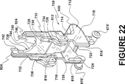
摺動子550と同様に、摺動アセンブリー708は一対の横方向に固定された並列ノブ674'および676'(図22参照)を有しており、これらは摺動子アセンブリー708が近位方向に変位するときに、案内トラック578'および580'に沿って移動するように拘束される大きさおよび配置になっている。摺動子550とは対称的に、摺動子アセンブリー708は遠位セクション710並びに近位セクション712を有している。
【0055】
近位セクション712は、形態および機能においてボタン640(図9〜図12参照)に類似したボタン640'を有している。先に開示したボタンと同様に、ボタン640'を使用することにより、摺動子アセンブリー708を近位方向に変位させて遠位セグメント704を近位セグメント706に対して折り畳み、針40を使用のために裸にし、また摺動子アセンブリー708を遠位方向に変位させてセグメント704および706を伸張させ、針40を保護的に取り囲むことができる。
【0056】
一対のヒンジ714および716(摺動子アセンブリー708が別の部分として示されている図22参照)は、近位セグメント712を遠位セグメント710にヒンジ結合させる。ヒンジ714および716は、摺動子アセンブリー708が射出成形されるときの一体ヒンジであってよい。摺動子アセンブリー708は、ハブアセンブリー540'、遠位セグメントおよび近位セグメント706と同様に、ポリプロピレンまたはその均等物を使用して射出成形すればよい。摺動子アセンブリー708と同様に、ハブアセンブリー540'、遠位セグメント704および近位セグメント706の成形可能な部分は、セグメント間ヒンジ、および以下で詳細に開示するハブとセグメントとの間のヒンジのために、一体ヒンジによって相互接続された単一の部分として射出成形してもよい。
【0057】
近位セクション712は更に、側部718および720の平行な外部を備えており、これらは一般に、上方に配置されたボタン640から、それぞれ内側に突出する一対の摺動レール722および724へと、下方にむけて伸びる。
遠位セクション710は、横行する平坦な頂部片728を有しており、これは、遠位セクション710および近位セクション712が折り畳まれ且つ整列されるときに、平坦な頂部片726と実質的に同じ平面内にある。平坦な頂部片728に対して直角に、一対の並列した側部730および732が配置されており、これらは平坦な頂部片728から延びて、夫々内側に向かう一対の底部レール734および736を形成する。セクション710もまた、内側に配置された舌部740および742によって、部分的に閉じられた円弧状の開口部738を有している。開口部738の内側表面744は、中央に配置された円弧状ノッチ746を有している。図18を再度参照すると、遠位セクション710は上方に突出するノブ748を有しており、該ノブは大径の上方部分および下方に配置された小径部分を備えている。
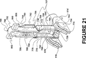
【0058】
組合されたハブアセンブリー540'(ルアーロックフィッティング572を伴わない)、遠位セグメント704および近位セグメント706の「成形できる物としての」表現が、図21に見られる。近位セクション706は、夫々のヒンジ754および756によって各ガイド574'および576'にヒンジ結合されており、このヒンジは近位セグメント706が、図21に示すようにハブアセンブリー540'に対して直交する状態にまで回転し、また図18に示すように針40の長軸に沿って展開された状態にまで回転するのを可能にする。
【0059】
近位セグメント706は、図18および図21の夫々の側に見られるように、実質的に平坦な頂部表面762を有する。頂部表面762から直交して下方に広がっているのは、一対の実質的器平行な側部764および766であり、図21に最も良く示されている。各側部764および766の底部には、それぞれ線形のインデント768および770がある。インデント768は、遠位ストッパ772および近位ストッパ774によって境界が設けられている。同様に、インデント770は、遠位ストッパ776および近位ストッパ778によって限定されている。これらストッパ772、774、776および778の目的および機能については、以下で詳細に開示する。
【0060】
遠位セグメント704はまた、実質的に平坦な頂部780と、横方向外側に広がる一対の並列翼部を有しており、一方の翼部782が図21に示されている。ここには782'で示す他方の翼部は示されていないが、それは翼部782のミラーイメージである。遠位セクション704は、頂部780に直角に結合された一対の並列された側部部材784および786を有している。各側部部材は複数の下方に広がるリブを有しており、これらリブは分離されて、針40のためのチャンネル788を形成する。同様に、側部764および766もまた同様に分離されて、セグメント704がセグメント706と整列するときにチャンネル788と連続する同様のチャンネル790を提供する。
【0061】
遠位部位792に、セグメント704は閉鎖端794を有している。閉鎖端794は、それによって針チップ100が拘束される隙間通路を与えるノッチ796を有していてもよく、部位792から外側は透明であってもよく、セグメント704の如何なる部分とも接触しない。また、閉鎖端794に対して近位に配置されているのは、一対の並列された実質的に矩形の部材800および802であり、その目的および機能については以下で詳細に説明する。頂部780の上部に配置されているのは、球状ノブ806において最高点に達するステム804(図18参照)である。ステム804および部分752の中心点は、針40の長軸と整列する線の中にある。
【0062】
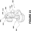
先に開示したアーム582のガイド600と同様に、セグメント704は、図18に示すように、それに取付けられた針ガイド600'を有する。針ガイド600'は、表示の明瞭さのために別の部分として図23に示されている。しかし、ガイド600'は、遠位セグメント704と共に一体成形されるのが好ましい。ガイド600'は、近位に配置された案内リング604を有しており、これは針40(図23には示されていない)を容易に通過させる寸法の、中央に配置されたスルーホール606'を有している。リング604'は、セグメント704および706が折り畳まれて針40を裸にするときに、チップ100がセグメント704の何れかの部分(特に閉鎖端794)に接触しないようにして、針40を拘束および案内するように幾何学的に配置すべきである。この方法において、チップ100は、損傷または汚染されることなく端部794を通過するように案内される。針ガイド600'はまた、カバー部分610'および一対の側部プロテクタ612'および614'と共に遠位に配置された囲い608'を有している。側部プロテクタ612'および614'、並びにカバー部分610'は内部表面615'および開口部616'を定義し、セグメント704および706が折り畳みおよび伸張されるときに、針40は前記開口部を通して滑動する。針ガイド600'は、別々の部分として形成されるときは、図25、図28および図30に示すように、ヒンジ602'において使用するために配置された横行スルーホール618'を有する。ヒンジ602'の位置を定義する際には注意を払うべきである。以下の開示から明らかになるように、セグメント704が折り畳まれるときに、部材800および802(図24参照)が針40の長軸と連続的に整列するようにして、針40の回りでのセグメント704の回転を可能にするように、ヒンジ602'を配置することが極めて重要である。
【0063】
図18を参照すると、ステム804およびノブ748の部分752は、摺動子アセンブリー708がシールド707に対して近位方向に変位するときに、エネルギーを蓄えるために使用されるエネルギー蓄積弾性リングである。しかし、図18に示すように、リング808は歪むことなく、ベアリング針チップ100のプロセスにおいて摺動子アセンブリー708が近位方向に変位するまではそのままである。リング808は、摺動子アセンブリー708を遠位方向に変位させて、一時的ラッチに係合するために充分な弾性をもった弾性材料で作製されるべきである。リング808は、頂部780およびノブ748および804によって、ステム804および部分752に取付けられたままであるように拘束される。摺動子アセンブリーが近位方向に変位されるときに歪み、摺動子アセンブリー708を図18に見られる状態に戻すための、充分な反発力を有する金属もしくはプラスチックのばね、または、他の部材のような何等かのエネルギー蓄積部材が、本発明の範囲内において使用され得る。
【0064】
図17、図19および図20に示すように、摺動子アセンブリー707を近位方向に変位させると、摺動子アセンブリー、並びに遠位セグメント704および近位セグメント706を、図17に見られる伸張状態から図19に示した中間状態を通して、図20に見られる折り畳まれた状態にまで折り畳ませる。図17の伸張された状態にあるとき、シールド707は安全のために確実にラッチされるが、解除可能である。
【0065】
図22を再度参照すると、ここには解除可能なラッチ部材が示されている。底部レール736と同一平面内の線に沿っているのは、近位セクション712の側部720に沿って配置された更に近位のレール810である。同様のレール812(図22では隠されている)が、近位セクション712の側部718に沿って同様に配置されている。組立てに際して、摺動子アセンブリー708の底部レール734および736は、それぞれ翼部782および782'の回りに摺動可能に係合される。各翼部(例えば図21に見られる翼部782)は、レール810および812の一方のレールによって形成されるラッチのための受け止め部を形成する。
【0066】
更に、摺動子アセンブリー708が摺動可能にシールド707に結合されるとき、側部718および720は、近位セグメント712の側部764および766の回りに配置されて、レール722および724が、それぞれ線型(リニア)インデント768および770上を摺動するようになっている。こうして、摺動子アセンブリー708の近位セグメント712への結合は、ポリプロピレンまたはその均等物のような可撓性の弾性材料を摺動子千部理-708のために使用することによって、またレール722および724のためにベベル加工された縁部814および816をそれぞれ向けることによって容易になり、これは摺動子アセンブリー708が近位セグメント712と「スナップ」係合するのを可能にする。こうして係合されると、レール722および724は、ストッパ774および778並びに768および776の間で近位方向および遠位方向に摺動するように拘束され、従ってこれらストッパによって制限される。
【0067】
シールド707および摺動子アセンブリー708が図17に示すように配置されると、レール810および812は翼部782'および782とそれぞれ係合する。この係合は、全てのヒンジ758,760,714または716の動作を抑制する。例えばボタン640に加えられた力の下で摺動子アセンブリー708が近位方向に変位されて初めて、このようなラッチは受け止め部から外され、またヒンジ758,760,714および716は自由に回転する。この同じ動作によって、弾性リング808は歪みを受け、結果的にその中にエネルギーが蓄えられる。この点において、ヒンジ758および718、760および714は、針40の長軸に対して横向きに整列されるべきである。また、ヒンジ、ラッチおよび受け止め部の解除と同時に、ノブ674'および676'のステムはトラック578'および580'の中にそれぞれ変位されて、ヒンジ758,760,714および716を付勢して針40から上方にリフトし、それによって図19および図20に示すように、シールド707を摺動子アセンブリー708と共に折り畳む。摺動子アセンブリー708およびシールド707は、図20においては、細部を明瞭に示すために、シリンジに接続しないで拡大された断面で示されている。
【0068】
ボタン640に対する力を反転させると、シールド707およびシールドアセンブリー708を針40の回りに伸張される。シールド707および摺動子アセンブリー708が伸張されると、弾性リング808の反発力が、レール810および812を翼部に対して再係合させる。シールド707および摺動子アセンブリー708は再度解除可能にラッチされる。永久的なラッチは、プラスチック設計の技術における当業者が理解するであろうように、図9〜図13に開示した方法で達成され得る。
【0069】
医療針を有効にカバーし、またこれに再アクセスすることにより、時間および距離によって離間された複数回の医療処置を、単回使用の安全針を用いたときには可能でない安全性で、同じ針を使用して行うことができる。しかし、不注意で針を突き刺す機会を非常に頻繁に与えるような、針の挿入を必要とする多くの共通の医療処置が存在する。これは、患者から血液を抜き取り、この血液を分析のために真空サンプル管に移すために、シリンジが使用されている場合である。この場合、患者から除去した後の屡々汚染された針は、如何なる安全機構の利益も伴わずに、真空サンプル管のストッパを通して導入される。
【0070】
同様に、シリンジが薬瓶から充填されるときには、医療処置においてシリンジの内容物を使用する前に、針は裸にされてバイアル瓶の膜に刺し通される。それは針に再キャップする標準の予防措置に反しているから、針はカバーされないで患者の場所に搬ばれる可能性がある。
【0071】
不注意により針で突き刺すことが問題になる場合のもう一つの例は、静脈注射(IV)部位の「Y」接合部においてである。このような目的のために、「無針システム」が多くの例において針を置き換えている。しかし、これはコスト無しでは達成されない。歴史によって、これらの代替無針は針単独よりも遥かに効果であることが示されている。
【0072】
勿論、患者への直接の皮下導入は、汚染された針での不注意による突刺しの最も顕著な機会であろうと思われる。医療処置で使用するために針が裸にされる毎に、健康ケア作業者または患者を危険に曝す汚染の機会が存在する。これらの針は、以下に開示する装置700使用および適用を広げる動機付けになっている。
【0073】
次に、図24〜図34を参照するが、ここにはシリンジのための安全なコネクタまたはアダプタをパッシブに活性化することに関連した方法および装置が開示される。図24において、バイアル瓶(小びん:小型容器)900およびバイアル瓶アダプタ902に関連して、シリンジ702に取付けられた装置700が見られる。バイアル瓶900は如何なる一般的な瓶であってもよく、そこから液体がシリンジの中に抜き取られ、またはシリンジの内容物がシリンジからバイアル瓶(例えば血液培養ボトル)の中に注入される。バイアル瓶900は、患者に皮下供給するために薬物が抜き取られるバイアル瓶であると看做されるのが最も多い。
【0074】
アダプタ902は、バイアル瓶900と装置700との間のコネクタであり、これは、それによってラッチを解除する施錠(キーイング)アクチュエータに対する、並びに、それによってシールド707が針チップ100から遠くへ選択的に折り畳むツールに対するインターフェースを提供する。図26に示すように、アダプタ902は、それによってアダプタ902がバイアル瓶900に固定されるスナップまたは取り付けリング904と、液体がそれを通して、通常はシリンジ針40を介してシリンジの中に抜き取られる刺し通し可能なアクセス膜上に配置される実質的に平坦な面906とを有している。
【0075】
一対の接続部材908および910が、面906から外側に突出している。各接続部材908および910は一対の外側に突出したプロングを有し、これらは中空キャビティー916を定める。本発明の範囲内において他の幾何学形状を使用してもよいけれども、それぞれのキャビティー916は断面が実質的に円形である。プロング912および914の間には、バイアル瓶アクセスオリフィス918が配置されており、それを通して針チップ100および針40が通過し、バイアル瓶902の刺し通し可能な膜を貫通する。各プロング912および914は、平坦な表面920と共に急激に終端するが、その目的については以下で詳細に開示する。アダプタ902のようなアダプタは、シールド707と共に相互作用的に使用し得るコネクタとして作用するために充分な剛性を有し、またプラスチックコネクタとして使用するための充分な反発弾性を有するポリプロピレンまたはその均等物で製造すればよい。
【0076】
各プロング対912および914は、それぞれ内側に配置された一対の湾曲表面912'および914'を有しており、これらは所定の距離だけ分離されている。図18を参照すると、部材802は、矢印922および922'で表された予め定められた断面幅を有している。部材800は、同様の予め定められた断面幅を有している。図24および図27の組合せの中に見ることができるように、アダプタ902の使用を介して針チップ100への保護されたアクセスを選択的に得るために、プロング対912および914(図26参照)は、部材800および802が関連のプロング湾局面912'および914'によって完全に通過されるまで変位される。それぞれの湾曲表面912'および914'を分離する最小の所定距離は、部材800および802の断面幅よりも幾分小さくすべきである。例えそうでも、プロング対の反発弾性は、夫々の部材800および802が、過大な力を伴わずに関連のキャビティー916の中に通るのを可能にするために十分でなければならない。
【0077】
図22を参照すると、夫々の舌部740および742は、遠位に配置された平坦な表面924を有しており、それはアダプタ902が部材800および802の回りに接続されるときに、表面920に衝撃を与えるような大きさおよび配置である。このような接続部を形成する動作は、舌部740および742を変位させて、近位方向に変位された摺動子708を生じさせることである。この方法において、プロング912および914の受け止め部の組は、舌部740および742(これらは、それぞれ部材800および802による変位から保護される)を変位させ、それによって摺動子708および摺動子707の間でのラッチングインターフェースの選択的な解除を行う。ボタン640を近位方向に変位させると、摺動子708が受け止め部からラッチを解除させ、シールド707が針保護状態から針40のアクセス状態へと折り畳まれるのを可能にするのと丁度同様に、部材800および802に対する接続アダプタ902は、舌部740および742を介して同じ動作を生じる。
【0078】
アダプタ902のようなアダプタまたはコネクタを介して針40を膜の中に供給する一つの重要な因子は、針が遠位方向または近位方向に移動するときに、針40の長軸と整列していない力から生じる過大な応力が、針40に加えられるべきでない点である。これを達成するために、部材800および802は、針40の長軸回りでの、シールド707の遠位セグメント704の回転横断線に沿って配置されなければならない。この回転線は、ヒンジ602の回転軸および針ガイド600'の孔606'の展開(図28参照)により、組合せにおいて決定される。適正な展開は、過大なトルクまたは曲げ力が、針40に加えられないことを保証する。これは、小径の針を使用するときに特に重要である。
【0079】
受動的操作は、装置を動作させるために通常用いられるステップ以外に、追加のステップを必要としない操作であると定義される。針アクセスは、追加のステップを伴うことなく、針40によるバイアル瓶900の中へのアクセスを与えるように一緒に動作する、シールド707およびアダプタ902を用いて提供される。図24に示されるように、先にバイアル瓶900に取り付けられたアダプタ902は、シリンジに取付けられた何等かの針チップの方への標準バイアル瓶の変位と同様の方法で、針チップ100(図24では隠れているが、図25では針ガイド600'に接触しない針チップ100と共に明瞭に見える)の方に変位される。部材800および802の回りでのプロング912および914の変位により、摺動子708の変位およびシールド707の最終的な回転を生じる。図27参照。図27において、シールド707の回転により、プロング912および914に対する部材800および802の同様の回転を生じ、それによって、関連キャビティー916内での夫々の部材800および802(図27には見られない)の捕捉をもたらす。部材800および802は、シールド707がもう一度完全に伸張される(針保護状態に広げられる)まで、固定および捕捉される。
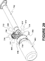
【0080】
針ハブアセンブリー540の方に向かうアダプタ902の近位方向の変位によって、針ガイド600'は、図28に示すように、針チップ100および針40をシールド707から遠くに付勢させる。連続的な変位は、針チップ100がアクセスオリフィス918を通って、図29に見られるようにバイアル瓶1900の中に向かうようにする。図30には、アダプタ902が正しい場所にある完全に折り畳まれたシールド707が見られる。
【0081】
先に述べたように、現在は裸の針を使用するのが通常の実務であるような、針を保護する多くの機会が存在する。最も普通の機会は、皮下適用において見出すことができる。アダプタ900に類似した接続素子を、図31に示す装置930のような平坦なプレート装置に適用することによって、皮下処置においても同様に受動的な針保護を与えることができる。装置930は、皮膚とのインターフェースを与えるように設計された平坦なプレート932を有している。アダプタ902と同様に、プレート932は一対の外側に突出した接続部材908および910を有している。アダプタ902の取付けリング904ではなく、装置903は、針40が皮下処置の終了時に抜き取られるときに、装置930を皮膚に当接して保持するために使用する一対の翼部934および936を有している。アダプタ902の場合のように、装置930はポリプロピレンまたはその均等物から、好ましくは射出成形によって製造される。
【0082】
アダプタ902に類似したコネクタまたはアダプタは、種々の他の針保護適用のために使用してもよい。このような適用の例は、図32〜図35に示されている。
【0083】
図32は、真空サンプリング管940に取り付けられた接続アダプタ902'を示している。アダプタ902'は、一対の外側に突出した部材908'および910'を有しており、これらは形態および機能において、対応する部材908および910に類似している(図26参照)。アクセスオリフィス918'(オリフィス918に類似)は、針チップ100および針40が横切って、真空サンプリング管940のストッパを刺し通すための通路を提供する。プロング942および944は、プロング912および914(図24〜図30参照)によって与えられるインターフェースと同等の、装置700に対するインターフェースを提供する。
【0084】
図33は、IVセット952の「Y」接合部950に取り付けられた接続アダプタ902''を示している。アダプタ902''は、一対の外側に突出した接続部材908'および910'を有しており、これらはその形態および機能において、接続部材908および910(図26参照)と類似している。アクセスオリフィス918''(オリフィス918'に類似)は、針チップ100および針40が、「Y」注入部位950の膜を横切って刺し通すための通路を提供する。図32に示した装置における場合と同様に、プロング942および944は、プロング912および914(図24〜図30参照)によって与えられるインターフェースと同等の、装置700に対するインターフェースを提供する。
【0085】
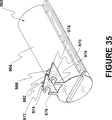
図34および図35は、そこから血液サンプル抜き取られる臍帯コード(図示せず)のための容器960を描いている。容器960は外表面964に取付けられるコネクタ962を有しており、これは、針チップ100にオリフィス966を通して臍帯コードへの保護アクセスを与えるように形成される。コネクタ962は一対の外側に突出した接続部材970および972を有しており、これらは形態および機能において、接続部材908および910(図26参照)に類似している。しかし、コネクタ962の場合、接続部材は、オリフィス966を通して、臍帯コードの中への斜めの導入を容易にするように配置されたプロング974および976を有している。容器960は、アダプタ902'および902"の場合と同様に、好ましくは、ポリプロピレンから射出成形される。図34における容器960の状態は、「成形された構成のまま」で好ましいものである。このように、容器960は、容器960の二つの半型982および984をヒンジ結合する一体ヒンジ980を含んでいる。半型982は、外縁988に沿って形成された一連のラッチ(夫々のラッチには986の番号が付されている)を有している。半型984は、容器960が使用のために臍帯コードの回りに閉じられるときに関連の夫々のラッチ986および988に並列される、外縁992に沿った複数のスロット990を有している。夫々の半型986および988は、容器が閉じられるときにコードクランプの半分を形成する、少なくとも一つの細長いインデント994を有している。
【0086】
本発明は、その精神または本質的な特徴を逸脱することなく、他の特定の形態で実施されてもよい。従って、上記で述べた実施例は、全ての点で例示的且つ非限定的なものと見なされるべきものであり、本発明の範囲は上記の説明によってではなく特許請求の範囲によって示され、従って、特許請求の範囲の意味およびその均等の範囲内にある全ての変更は、本発明の中に包含されるものである。
【0087】
特許の権利が請求され、且つ特許による保証が望まれる事項は、特許請求の範囲に記載した通りである。
【図面の簡単な説明】
【図1】 図1は、針カバーおよび針シールドを備えた衣料針シールドアセンブリーの一実施例を示す図であり、これは医療針への再アクセスを可能にすると共に、針へのアクセスを必要とする処置の間で保護カバーを針上に維持し、且つ全ての望ましい処置が完了したときには、永久的な針保護を与えるように前記シールドを安全且つ永久的にロックする。
【図2】 図2は、カバーが除去された状態の、図1の医療針シールドアセンブリーを示す斜視図である。
【図3】 図3は、静脈切開に使用される医療針のように二つの尖った端部および螺合可能なハブを有する変形を備えた、図2と同様の斜視図である。
【図4】 図4は、シールドを部分的に変位させた状態で、図1に示す装置を示す斜視図である。
【図5】 図5は、針を保護的にカバーするようにシールドが完全に変位され、且つシールドが後退して針への反復アクセスを与えるように配置された状態の、図2および図4の医療針シールドアセンブリーの斜視図である。
【図6】 図6は、針への再アクセスを防止するようにシールドの一部が解除不能にロックされた状態の、図5に示した装置の斜視図である。
【図7】 図7は、図1〜図6に示したシールドの無針折り畳み部分を下から見た斜視図である。
【図8】 図8は、針シールドの摺動子部分の斜視図である。
【図9】 図9は、医療針の回りに保護的に配置されたシールドを示す本発明のもう一つの実施例の斜視図であり、シールドが針の回りに保護的に配置されるときに選択的に係合可能な、解除可能および解除不能な受け止め部を備えている。
【図10】 図10は、図9に示した装置の斜視図であり、医療針の尖ったチップを裸にするようにシールドが部分的に変位されている。
【図11】 図11は、図9に示した装置の斜視図であり、図10に示した実施例よりも医療針の尖ったチップが多く裸になるように、シールドが図10に示した変位よりも大きく変位されている。
【図12】 図12は、図9に示した装置の斜視図であり、そのシールドは完全に折り畳まれており、針および針チップを共に裸にしている。
【図13】 図13は、シールドが解除不能な状態に配置された状態の、図9に示した装置の斜視図である。
【図14】 図14は、「成形されたまま」の状態で配置された、図9に示した装置におけるシールドの一部の斜視図である。
【図15】 図15は、シールドに結合された摺動子部分の斜視図である。
【図16】 図16は、シールドに結合された針ガイドの斜視図である。
【図17】 図17は、シリンジに取付けられる針シールドアセンブリーのもう一つの実施例を示す斜視図である。
【図18】 図18は、図17に見られる実施例の、取外された針シールドアセンブリーを示す斜視図である。
【図19】 図19は、針シールドアセンブリーが部分的に折り畳まれた状態の、図17の実施例の斜視図である。
【図20】 図20は、図18に示した針シールドアセンブリーの断面図であり、該アセンブリーは、関連の医療針へのアクセスのために折り畳まれている。
【図21】 図21は、関連の医療針がない針シールドを示す斜視図である。
【図22】 図22は、図18の針シールドアセンブリーにおける摺動子部分を示す斜視図である。
【図23】 図23は、針シールドの遠位セグメントに結合された針ガイドの斜視図である。
【図24】 図24は、図17の実施例、および、これに取り付けられたコネクタアダプタを有する薬瓶の斜視図である。
【図25】 図25は、図24に示した斜視図の断面図である。
【図26】 図26は、針シールドアセンブリーに結合されたコネクタアダプタの斜視図であり、図24に示されたものである。
【図27】 図27は、針シールドアセンブリーと連通して配置された図24のバイアル瓶およびコネクタアダプタ、並びに得られた針シールドアセンブリーの屈曲構造を示す斜視図である。
【図28】 図28は、相互接続されたバイアル瓶、コネクタアダプタ、および針シールドアセンブリーの断面図である。
【図29】 図29は、針シールドアセンブリーに係合およびこれを折り畳む、コネクタアダプタの斜視図である。
【図30】 図30は、表示を明瞭にするためにバイアル瓶を除去した、図29に示したコネクタおよび針シールドアセンブリーの断面図である。
【図31】 図31は、皮下適用に使用するためのアダプタを示す斜視図である。
【図32】 図32は、真空サンプリング管に取付けられたコネクタの斜視図である。
【図33】 図33は、「Y」注入部位に取付けられたコネクタの斜視図である。
【図34】 図34は、アダプタが取付けられた臍帯コード容器を開いた状態で示す斜視図である。
【図35】 図35は、取付けられたアダプタを見るために閉じられた、図34のコード容器の斜視図である。[0001]
FIELD OF THE INVENTION
The present invention relates generally to a hollow lumen medical needle safety device, and more particularly to a syringe needle device that uses a protective needle shield or protective needle sheath to safely shield a sharp needle tip and is used before and after a medical procedure. The More particularly, the present invention relates to a removable medical needle shield, sheath or enclosure, which can be used as a removable and repositionable protective needle cover. The present invention can also be used to further shield and protect the needle in use and can be locked to selectively remove the attached medical needle shield from the bowl tip of the device. Regarding the adapter.
[0002]
BACKGROUND OF THE INVENTION
The problems associated with inadvertent needle sticks are well known in other medical procedure techniques, including blood collection, percutaneous injection of medication, and the use of medical needles. Due to modern people's sensitivity to exposure to AIDS, hepatitis and other serious blood borne diseases, more attention is paid to the needle stick problem.
[0003]
Procedures involving removal of the needle from the patient typically require the practitioner to press the wound site where the needle is removed with the other hand while removing the needle device with one hand. The attending practitioner usually prioritizes attention to wound care over needle disposables. In the case of normal non-safety devices, such priorities are the convenience of available sharp containers that are easily accessible, or another means to safely dispose of them without leaving them on the patient's side. Need. Providing adequate care with safe treatment is often complicated by the patient's physiological and mental conditions (eg, burn units and psychiatric). Under such conditions, it is often difficult, if not impossible, to take appropriate action to properly dispose of used exposed needles while caring for the patient. The usual practice of filling a syringe with a medicament at one location and then transporting it to the patient's location without capping the needle gives a prominent machine to accidentally pierce with a needle. Re-capping the needle is not allowed in current US medical practice because of the danger of accidental needle sticks associated with re-capping.
[0004]
The well-known knowledge and history associated with needle care and disposal issues has resulted in a number of devices to prevent accidental needle sticks. Current devices for shielding the needle of a syringe often require both hands, and in some devices the safety state of the needle shield is not readily apparent.
[0005]
Often, it is necessary to use the syringe needle multiple times. When performing intramuscular injection, it is normal practice to remove the contents from the vial and then inject the contents into the patient. It is desirable to use the same needle to puncture the membrane on the vial and then inject it into the patient. However, the location where the contents are extracted from the vial may be some distance from the location where the patient is injected. In such situations, the practitioner may re-capping the needle for delivery to the patient. Equally problematic is another practice of carrying unprotected needles. Some currently available safety devices allow needle cover and re-access. However, factors such as those disclosed above limit the tolerance of these safety devices.
[0006]
Recognizing the need for safety even in situations where the needle is intruding into a relatively safe area (eg, through a “Y” connector in an IV set) is commonly known as a “needleless system” Has been successful in the design and sale of different types of medical devices. However, even with these systems, the procedure of filling the vial does not completely preclude the use of the needle, as it still requires the use of a sharp needle to fill the syringe. Once the syringe is filled, remove and discard the used needle and replace it with a blunt cannula or connect to a needleless connector while the needle is exposed and remains dangerous during the syringe filling procedure. It is normal practice.
[0007]
There is still a need to provide a more satisfactory solution for needle safety devices that are re-accessible for multiple use.
[0008]
SUMMARY OF THE INVENTION
Briefly summarized, the novel invention disclosed herein is a known art that results from a puncture with a wound-related needle that occurs when the needle tip is bare when the medical needle is withdrawn from the patient at the end of the needle insertion procedure. It dramatically reduces serious problems. The present invention allows access to the medical needle at several steps in a medical procedure, while allowing the needle to be returned to a state surrounded by a secure cover during those steps. is there.
[0009]
The present invention uses a needle protection shield that is movable to cover and protect the tip of the needle and moves the needle and tip to be bare for multiple use throughout the medical procedure. Can do. Furthermore, in addition to the protective tip of the needle being protected by the shield, it does not contact the shield.
[0010]
In the present invention, a shield is placed around the needle and tip to provide protection. A releasable temporary latch is provided, which can be removed to fold the shield, thereby allowing the needle to be reaccessed for subsequent medical procedures. When each procedure is complete, the shield is re-expanded and latched to provide a safe cover. A selectively activated non-releasable lock is also provided for a protective shield that compensates for reliable needle tip protection at the end of use.
[0011]
In one embodiment, the shield includes a needle guide disposed proximally with respect to the needle tip, which moves the protective shield to cover and shield the needle and to remove the shield. And when you are bare to use the needle, protect the tip from damage due to contact with the shield. The needle guide is positioned and restrained to move in alignment with the long axis of the needle and is restrained to facilitate movement of the shield around the needle without contacting the needle tip. The
[0012]
In general, the device can be configured in at least two states, temporary or releasable but stable. In one stable state, the shield is constrained to be placed “out of the way” when the needle is bare for use. In the second releasable stable state, the shield is constrained to be placed protectively around the needle and needle tip. In addition, the device and shield include a permanent lock that, when combined, is securely and non-removably secured to prevent further use of the device when use is complete. Preferably, a latch is used to constrain the shield to its respective stable state.
[0013]
Other important factors in the safety needle device include that the device can be used effectively with one hand and that the needle can be accessed multiple times while maintaining the needle in a safe state during use. It is. In particular, in the case of a hypodermic syringe needle device, to prefill the syringe, the needle is used to access the vial containing the medical fluid and then the same needle is used to transfer the syringe contents to the patient. The ability to access the medical needle multiple times from a safe state is very important, as it is normal practice to supply
[0014]
The present invention generally relates to the user from inadvertent needle injury when the device is moved towards the safe state of the shield, removed from the safe state, or simply placed within the safe state. It provides one-handed operation and multiple access to the medical needle while protecting the needle and protecting its fragile tip.
[0015]
However, even if a needle shield is effective, the needle is prone to inadvertent puncture when used in standard procedures to bare the needle, such as occurs in subcutaneous applications. For this reason, the needleless system has become popular. One embodiment of the present invention includes combining a needle shield with a special connector (or adapter) to provide functional access to the needle while maintaining the needle under a continuous protective cover.
[0016]
In such an embodiment, each deployed shield base has a distally located latch that can be placed in place as a preventive measure against inadvertent folding. Lock it. Each connector or adapter has an actuator and a key. These allow the latch to be unlocked by the action of connecting the connector or adapter to the shield, thereby removing (folding) the shield from the needle while maintaining a continuous protective cover around the needle tip. ) Becomes possible. In conjunction with the removal of the shield, movement toward the needle tip of the connector or adapter takes place in the direction of the connector adapter and a linear path into it (which is aligned with the long axis of the needle). . In this method, there is no tendency for the needle to bend when using the connector. The needle tip is continuously protected by the shield until it enters the connector or adapter. Since the needle tip is continuously covered and protected, the safety of the needle is guaranteed for all purposes where the shield is used with a connector or adapter.
[0017]
Such objectives are generally met by the same number and types of steps required when performing the same function without the use of connectors or adapters. For this reason, most operations using these connectors that work with shields are considered passive operations (ie they require a step in addition to standard treatment steps without shields and connectors). And not). Passive operation is further realized by the interaction between the connector and the shield which serves to automatically return the shield to the extended needle protection state when the needle is withdrawn from the connector. As with connecting and folding the shield, the needle tip is continuously covered as the needle is withdrawn from the connector. Thus, the shield ensures that the needle is fully protected before the connector is removed, thereby ensuring safety before, during and after use of the needle.
[0018]
Within the scope of the present invention there are many applications where such connectors can be used safely and effectively. For example, but not limited to, connectors may be placed on vials, intravenous (IV) tube sets, and vacuum sampling tubes.
[0019]
Briefly summarized, the above objective is accomplished by a medical needle safety system for repeated access to a medical needle from a needle tip protection shield in sequential use of the needle, the safety system including an elongated medical needle and a needle hub. Comprising a medical needle assembly, said medical needle being fixed to said hub and having a pointed tip disposed distally and a long axis disposed intermediately along a line from said hub to said tip A safety shield assembly hinged to the hub, the safety shield assembly comprising a plurality of foldable segments, each segment being hinged to at least one other segment, wherein at least one of the segments Is arcuate to swivel about the long axis of the needle, and the shield assembly is even less Also includes a releasable latch portion that latches when the shield is extended around the needle and is independent of a needle that is protectively disposed about the needle and needle tip. And securing the shield for the purpose of providing a substantially rigid structure, and thereby releasing the latch so that the shield can be folded back and the needle and needle tip are bare for use. And an actuator that allows it to later re-extend around the needle and its tip.
[0020]
DESCRIPTION OF THE PREFERRED EMBODIMENT
In this description, the term “proximal” is generally used to indicate the item referred to relative to the expected user of the device, unless otherwise specified. The term “distal” is also used to indicate the more distant. Reference is now made to the embodiment shown in FIGS. 1-35, in which like numbers are used to designate like parts throughout. Where multiple parts have similar but not identical forms and functions, primed numbers are used to facilitate interpretive cross-references.
[0021]
A first embodiment of a needle shield safety device according to the present invention is shown in FIG. The
[0022]
The
[0023]
In addition to the
[0024]
It is important to note that a cover such as
[0025]
The first inventive novelty of this embodiment is the
[0026]
The
[0027]
[0028]
A pair of laterally extending
[0029]
An important element of the
[0030]
Reference is now made to FIG. 7, where the detailed structure of the
[0031]
As best seen in FIG. 8, the
[0032]
The
[0033]
Another
[0034]
Therefore, the
[0035]
In another embodiment 30 ', the
[0036]
An
[0037]
Coupled to the
[0038]
The
[0039]
[0040]
[0041]
The
[0042]
A pair of hinges 638 and 639 (see FIG. 14) hinge the
[0043]
Next, referring to FIG. 15, there is shown a
[0044]
The distal
[0045]
Proximal
[0046]
Referring to FIG. 9, the
[0047]
FIG. 9 shows the status of the
[0048]
After removing the
[0049]
When the
[0050]
By applying a distal force on the
[0051]
Once the medical procedure is complete and it is determined that the
[0052]
Another device attached to the syringe barrel 1702 shown in FIG. 17 can also be used to re-access the medical needle without the undue risk of inadvertent needle sticking. The
[0053]
[0054]
Similar to the
[0055]
[0056]
A pair of
[0057]
The
[0058]
A “as moldable” representation of combined
[0059]
[0060]
The
[0061]
At
[0062]
Similar to the previously disclosed
[0063]
Referring to FIG. 18, the
[0064]
As shown in FIGS. 17, 19 and 20, when the
[0065]
Referring again to FIG. 22, there is shown a releasable latch member. Along the line in the same plane as the
[0066]
Further, when the
[0067]
When
[0068]
Reversing the force on
[0069]
By effectively covering and re-accessing the medical needle, multiple medical procedures separated by time and distance can be performed with the same needle, with safety not possible when using a single-use safety needle. Can be done using. However, there are many common medical procedures that require the insertion of a needle that give the opportunity to inadvertently pierce the needle very often. This is the case when a syringe is used to draw blood from the patient and transfer this blood to a vacuum sample tube for analysis. In this case, often contaminated needles after removal from the patient are introduced through the stopper of the vacuum sample tube without the benefit of any safety mechanism.
[0070]
Similarly, when a syringe is filled from a vial, the needle is bare and pierced through the vial membrane before using the syringe contents in a medical procedure. Because it violates standard precautions to recap the needle, the needle can be uncovered and taken to the patient's location.
[0071]
Another example where inadvertent puncture becomes a problem is at the “Y” junction at the intravenous (IV) site. For this purpose, a “needleless system” replaces the needle in many instances. However, this cannot be achieved without cost. History has shown that these alternative needleless are much more effective than needles alone.
[0072]
Of course, direct subcutaneous introduction to the patient appears to be the most prominent opportunity for inadvertent puncture with a contaminated needle. Every time a needle is bare for use in a medical procedure, there is a chance of contamination that endangers the health care worker or patient. These needles are motivated to expand the use and application of the
[0073]
Reference is now made to FIGS. 24-34, which disclose methods and apparatus related to passively activating a secure connector or adapter for a syringe. In FIG. 24, a
[0074]
The
[0075]
A pair of connecting
[0076]
Each
[0077]
Referring to FIG. 22, each
[0078]
One important factor that feeds the
[0079]
Passive operations are defined as operations that do not require any additional steps beyond those normally used to operate the device. Needle access is provided using a
[0080]
Due to the proximal displacement of the
[0081]
As mentioned earlier, there are many opportunities to protect the needles where it is now normal practice to use a bare needle. The most common opportunity can be found in subcutaneous application. By applying a connecting element similar to the
[0082]
A connector or adapter similar to
[0083]
FIG. 32 shows the
[0084]
FIG. 33 shows the
[0085]
34 and 35 depict a
[0086]
The present invention may be embodied in other specific forms without departing from its spirit or essential characteristics. Accordingly, the embodiments described above are to be considered in all respects as illustrative and non-limiting, and the scope of the invention is indicated by the appended claims rather than by the foregoing description, and accordingly All changes that come within the meaning and range of equivalency of the claims are to be embraced within the scope of the invention.
[0087]
The matters for which patent rights are claimed and guarantees are desired are as set forth in the appended claims.
[Brief description of the drawings]
FIG. 1 illustrates one embodiment of a garment needle shield assembly that includes a needle cover and a needle shield, which allows re-access to the medical needle and provides access to the needle. The protective cover is maintained on the needle during the required procedure, and when all desired procedures are complete, the shield is locked safely and permanently to provide permanent needle protection.
FIG. 2 is a perspective view of the medical needle shield assembly of FIG. 1 with the cover removed.
FIG. 3 is a perspective view similar to FIG. 2 with a deformation having two pointed ends and a threadable hub, like a medical needle used for phlebotomy.
FIG. 4 is a perspective view showing the apparatus shown in FIG. 1 with the shield partially displaced.
FIG. 5 shows FIGS. 2 and 4 with the shield fully displaced to cover the needle in a protective manner and the shield being retracted and arranged to provide repetitive access to the needle. FIG. 3 is a perspective view of the medical needle shield assembly of FIG.
FIG. 6 is a perspective view of the apparatus shown in FIG. 5 with a portion of the shield locked in a non-releasable manner to prevent re-access to the needle.
FIG. 7 is a perspective view of the needleless folded portion of the shield shown in FIGS. 1 to 6 as viewed from below.
FIG. 8 is a perspective view of a slider portion of a needle shield.
FIG. 9 is a perspective view of another embodiment of the present invention showing a shield placed protectively around a medical needle, when the shield is placed protectively around the needle. A releasable and non-releasable receiving portion that can be selectively engaged is provided.
FIG. 10 is a perspective view of the apparatus shown in FIG. 9, with the shield partially displaced to bare the pointed tip of the medical needle.
FIG. 11 is a perspective view of the apparatus shown in FIG. 9, in which the shield is shown in FIG. The displacement is larger than the displacement.
FIG. 12 is a perspective view of the device shown in FIG. 9, with its shield fully folded, leaving both the needle and needle tip naked.
FIG. 13 is a perspective view of the apparatus shown in FIG. 9 with the shield disposed in an unreleasable state.
FIG. 14 is a perspective view of a portion of the shield in the apparatus shown in FIG. 9 placed “as-formed”.
FIG. 15 is a perspective view of a slider portion coupled to a shield.
FIG. 16 is a perspective view of a needle guide coupled to a shield.
FIG. 17 is a perspective view showing another embodiment of a needle shield assembly attached to a syringe.
FIG. 18 is a perspective view showing the removed needle shield assembly of the embodiment seen in FIG.
FIG. 19 is a perspective view of the embodiment of FIG. 17 with the needle shield assembly partially folded.
FIG. 20 is a cross-sectional view of the needle shield assembly shown in FIG. 18, which is folded for access to an associated medical needle.
FIG. 21 is a perspective view showing a needle shield without an associated medical needle.
FIG. 22 is a perspective view showing a slider portion in the needle shield assembly of FIG. 18;
FIG. 23 is a perspective view of a needle guide coupled to a distal segment of a needle shield.
24 is a perspective view of the medicine bottle having the embodiment of FIG. 17 and a connector adapter attached to the embodiment. FIG.
25 is a cross-sectional view of the perspective view shown in FIG. 24. FIG.
FIG. 26 is a perspective view of the connector adapter coupled to the needle shield assembly as shown in FIG. 24.
FIG. 27 is a perspective view showing the vial and connector adapter of FIG. 24 placed in communication with the needle shield assembly, and the resulting bent structure of the needle shield assembly.
FIG. 28 is a cross-sectional view of an interconnected vial, connector adapter, and needle shield assembly.
FIG. 29 is a perspective view of the connector adapter engaging and folding the needle shield assembly.
30 is a cross-sectional view of the connector and needle shield assembly shown in FIG. 29 with the vial removed for clarity of display.
FIG. 31 is a perspective view showing an adapter for use in subcutaneous application.
FIG. 32 is a perspective view of a connector attached to a vacuum sampling tube.
FIG. 33 is a perspective view of a connector attached to a “Y” injection site.
FIG. 34 is a perspective view showing the umbilical cord container to which the adapter is attached in an opened state.
FIG. 35 is a perspective view of the cord container of FIG. 34 closed to view the installed adapter.
Claims (3)
細長い医療針、および、針ハブを含む医療針アセンブリーを備え、
前記医療針は、前記ハブに固定され、且つ、遠位に配置された尖った針チップ、および、前記ハブから前記針チップへの線に沿って中間に配置される長い軸を有しており、
前記医療針安全システムは更に、前記ハブにヒンジ結合され、かつ、シールドを有する安全シールドアセンブリーを備え、
前記シールドは、各々のセグメントが、少なくとも一つの他のセグメントにヒンジ結合される複数の折り畳み可能なセグメントを含んでおり、
前記シールドアセンブリーは更に、少なくとも一つのラッチ部分を含み、
前記ラッチ部分は、近位セグメントに対して摺動可能なように固定されており、
前記ラッチ部分は、前記シールドが伸張されて前記針チップを保護するときに、遠位セグメントに対して解除可能および解除不能に接続するためのラッチを含んでおり、
前記シールドが前記針の回りに伸張され、かつ、前記ラッチ部分が遠位方向に摺動されたときに、前記少なくとも一つのラッチ部分がラッチして、実質的に剛性の構造を与える目的で前記シールドを固定するように構成されており、
前記シールドアセンブリーは、更に、前記少なくとも一つのラッチ部分に形成されたアクチュエータを備え、
前記アクチュエータは、デジタルインターフェースを有しており、
前記デジタルインターフェースは、前記シールドアセンブリーに対して前記少なくとも一つのラッチ部分を近位方向に摺動させて、前記ラッチ部分を解除させ、前記シールドが折り畳み可能に後退し、前記針、および、前記針チップが使用のために裸にされ、また、後で、前記針、および、前記針チップの回りに再伸張することを可能にするように構成されている、
ことを特徴とする安全システム。In a medical needle safety system for sequential use of needles that can be used to repeatedly access a medical needle from a needle tip protection shield,
A medical needle assembly including an elongated medical needle and a needle hub;
The medical needle is fixed to the hub, and pointed needle tip located at a distal, and have a long axis that is disposed from the hub to the intermediate along the line to the needle tip ,
The medical needle safety system further comprises a safety shield assembly hinged to the hub and having a shield;
The shield includes a plurality of foldable segments, each segment hinged to at least one other segment ;
The shield assembly further includes at least one latch portion;
The latch portion is slidably fixed relative to the proximal segment;
The latch portion includes a latch for releasably and non-releasably connecting to a distal segment when the shield is extended to protect the needle tip;
When the shield is extended around the needle and the latch portion is slid distally, the at least one latch portion latches to provide a substantially rigid structure. Configured to secure the shield,
The shield assembly further comprises an actuator formed on the at least one latch portion,
The actuator has a digital interface;
The digital interface slides the at least one latch portion proximally relative to the shield assembly to release the latch portion, the shield is foldably retracted, the needle, and the A needle tip is bare for use and is configured to allow later re-expansion around the needle and the needle tip ;
Safety system characterized by that.
Applications Claiming Priority (3)
| Application Number | Priority Date | Filing Date | Title |
|---|---|---|---|
| US09/434,036 | 1999-11-04 | ||
| US09/434,036 US6254575B1 (en) | 1999-11-04 | 1999-11-04 | Reaccessible medical needle safety devices and methods |
| PCT/US2000/029971 WO2001032244A1 (en) | 1999-11-04 | 2000-10-31 | Reaccessible medical needle safety devices and methods |
Publications (3)
| Publication Number | Publication Date |
|---|---|
| JP2003516777A JP2003516777A (en) | 2003-05-20 |
| JP2003516777A5 JP2003516777A5 (en) | 2007-12-20 |
| JP4809560B2 true JP4809560B2 (en) | 2011-11-09 |
Family
ID=23722557
Family Applications (1)
| Application Number | Title | Priority Date | Filing Date |
|---|---|---|---|
| JP2001534447A Expired - Fee Related JP4809560B2 (en) | 1999-11-04 | 2000-10-31 | Re-accessible medical needle safety device |
Country Status (8)
| Country | Link |
|---|---|
| US (1) | US6254575B1 (en) |
| EP (1) | EP1289584A4 (en) |
| JP (1) | JP4809560B2 (en) |
| AU (1) | AU780915B2 (en) |
| CA (1) | CA2389299C (en) |
| MX (1) | MXPA02004472A (en) |
| NZ (1) | NZ518446A (en) |
| WO (1) | WO2001032244A1 (en) |
Families Citing this family (51)
| Publication number | Priority date | Publication date | Assignee | Title |
|---|---|---|---|---|
| US6749588B1 (en) * | 1998-04-09 | 2004-06-15 | Becton Dickinson And Company | Catheter and introducer needle assembly with needle shield |
| US7029461B2 (en) * | 1999-11-04 | 2006-04-18 | Tyco Healthcare Group Lp | Safety shield for medical needles |
| US6592556B1 (en) * | 2000-07-19 | 2003-07-15 | Tyco Healthcare Group Lp | Medical needle safety apparatus and methods |
| US8226617B2 (en) | 1999-11-04 | 2012-07-24 | Tyco Healthcare Group Lp | Safety shield apparatus and mounting structure for use with medical needle devices |
| US6280420B1 (en) | 1999-11-04 | 2001-08-28 | Specialized Health Products | Reaccessible medical needle safety devices and methods |
| DE20102760U1 (en) | 2001-02-16 | 2001-05-03 | B. Braun Melsungen Ag, 34212 Melsungen | Protective device for an injection needle with a curved tip |
| US6902546B2 (en) * | 2001-03-15 | 2005-06-07 | Specialized Health Products, Inc. | Safety shield for medical needles |
| US7413562B2 (en) | 2001-03-15 | 2008-08-19 | Specialized Health Products, Inc. | Safety shield for medical needles |
| JP3971933B2 (en) * | 2002-02-06 | 2007-09-05 | 株式会社吉野工業所 | Syringe |
| ES2240875T3 (en) * | 2002-03-21 | 2005-10-16 | Becton, Dickinson And Company | SAFETY NEEDLE DEVICE WITH A Dorsal FIN. |
| SG121744A1 (en) | 2002-11-06 | 2006-05-26 | Becton Dickinson Co | Flashback blood collection needle with needle shield |
| US7637891B2 (en) * | 2002-09-12 | 2009-12-29 | Children's Hospital Medical Center | Method and device for painless injection of medication |
| US7097637B2 (en) * | 2003-08-27 | 2006-08-29 | C. R. Bard, Inc. | Safety needle with positive flush |
| IL157981A (en) | 2003-09-17 | 2014-01-30 | Elcam Medical Agricultural Cooperative Ass Ltd | Auto-injector |
| US20050171483A1 (en) * | 2004-02-03 | 2005-08-04 | Dennis Williams | Needle cover extractor |
| US7896841B2 (en) * | 2004-02-17 | 2011-03-01 | Children's Hospital Medical Center | Injection device for administering a vaccine |
| IL160891A0 (en) | 2004-03-16 | 2004-08-31 | Auto-mix needle | |
| US7850650B2 (en) | 2005-07-11 | 2010-12-14 | Covidien Ag | Needle safety shield with reset |
| US7905857B2 (en) | 2005-07-11 | 2011-03-15 | Covidien Ag | Needle assembly including obturator with safety reset |
| US7828773B2 (en) | 2005-07-11 | 2010-11-09 | Covidien Ag | Safety reset key and needle assembly |
| WO2006113542A1 (en) * | 2005-04-15 | 2006-10-26 | Specialized Health Products, Inc. | Medical needle systems with reset devices for medical needle shield apparatus |
| US20060276747A1 (en) | 2005-06-06 | 2006-12-07 | Sherwood Services Ag | Needle assembly with removable depth stop |
| US7731692B2 (en) | 2005-07-11 | 2010-06-08 | Covidien Ag | Device for shielding a sharp tip of a cannula and method of using the same |
| US7654735B2 (en) | 2005-11-03 | 2010-02-02 | Covidien Ag | Electronic thermometer |
| JP4969642B2 (en) | 2006-03-21 | 2012-07-04 | タイコ ヘルスケアー グループ リミテッド パートナーシップ | Passive latching safety shield for injection devices |
| US8057431B2 (en) | 2006-12-21 | 2011-11-15 | B. Braun Melsungen Ag | Hinged cap for needle device |
| CN102266230B (en) | 2007-03-07 | 2014-05-14 | 贝克顿·迪金森公司 | Safety blood collection assembly with indicator |
| US8888713B2 (en) * | 2007-03-07 | 2014-11-18 | Becton, Dickinson And Company | Safety blood collection assembly with indicator |
| US7736340B2 (en) * | 2007-09-28 | 2010-06-15 | Becton, Dickinson And Company | Catheter insertion device with automatic safety barrier |
| US8357104B2 (en) | 2007-11-01 | 2013-01-22 | Coviden Lp | Active stylet safety shield |
| US8603009B2 (en) * | 2008-03-07 | 2013-12-10 | Becton, Dickinson And Company | Flashback blood collection needle |
| US8795198B2 (en) * | 2008-03-07 | 2014-08-05 | Becton, Dickinson And Company | Flashback blood collection needle |
| US7931622B2 (en) * | 2008-03-19 | 2011-04-26 | Smiths Medical Asd, Inc. | Tip protector for cannula, trocar and/or cannula trocar combination |
| US7938800B2 (en) * | 2008-05-13 | 2011-05-10 | Lawrence R. Koh and Nina Merrell-Koh | Needleshield assembly and methods of use |
| JP5952188B2 (en) * | 2009-07-31 | 2016-07-13 | メデイカル コンポーネンツ,インコーポレーテツド | Hoover needle with safety tube |
| EP2378342A1 (en) * | 2010-04-15 | 2011-10-19 | Mmi Ag | Micromanipulation system with protection device for capillaries |
| RU2584388C2 (en) | 2010-11-22 | 2016-05-20 | Б. Браун Мельзунген Аг | Hinged panel device and related methods |
| US8821453B2 (en) * | 2011-07-25 | 2014-09-02 | Safety Syringes, Inc. | Folding panel needle guard |
| US10307093B2 (en) * | 2013-03-15 | 2019-06-04 | Becton, Dickinson And Company | Placental and cord blood collection device with safety |
| RU2667823C2 (en) * | 2013-05-03 | 2018-09-24 | Алтавиз, Ллс | Device for filling syringe with gas and method of manufacture and use thereof |
| AU2014331691B2 (en) | 2013-10-10 | 2018-08-02 | Medical Components, Inc | Huber needle assembly with safety capture device |
| US9867951B2 (en) | 2014-04-08 | 2018-01-16 | B. Braun Melsungen Ag | Hinged cap needle assemblies and related methods |
| JP6730255B2 (en) | 2014-08-29 | 2020-07-29 | メデイカル コンポーネンツ,インコーポレーテツド | Huba safety needle |
| USD804021S1 (en) | 2015-02-27 | 2017-11-28 | Medical Components, Inc. | Huber safety needle |
| USD804022S1 (en) | 2015-02-27 | 2017-11-28 | Medical Components, Inc. | Huber safety needle |
| US10029049B2 (en) | 2015-03-19 | 2018-07-24 | B. Braun Melsungen Ag | Hinged shield assemblies and related methods |
| CN108778369B (en) | 2016-03-18 | 2021-05-25 | 医疗部件有限公司 | Hubeier safety needle |
| KR102115374B1 (en) * | 2016-10-25 | 2020-05-26 | (주)한빛상사 | needle sheath, and for wing typic catheter assembleassembly having the same |
| JP7444778B2 (en) * | 2018-02-02 | 2024-03-06 | ベクトン・ディキンソン・アンド・カンパニー | syringe assembly |
| US11224537B2 (en) | 2018-10-19 | 2022-01-18 | Alcon Inc. | Intraocular gas injector |
| CN111228611B (en) * | 2018-11-28 | 2021-08-31 | 河南科技大学第一附属医院 | Auxiliary drug delivery device for oral local anesthesia with built-in needle |
Family Cites Families (67)
| Publication number | Priority date | Publication date | Assignee | Title |
|---|---|---|---|---|
| US3587575A (en) | 1969-09-15 | 1971-06-28 | Lichtenstein Eric Stefan | Self-contained, moving needle syringe with hydraulic safety lock |
| US4040419A (en) | 1976-02-02 | 1977-08-09 | Abraham Goldman | Shielding holder for a syringe having indirect viewing means |
| US4106621A (en) | 1976-07-26 | 1978-08-15 | Sorenson Research Co., Inc. | Combination needle cover and venipuncture device tray and method of using same |
| US4270536A (en) | 1979-10-01 | 1981-06-02 | Lemelson Jerome H | Disposable syringe |
| US4846811A (en) | 1987-01-29 | 1989-07-11 | International Medical Innovators, Inc. | Sliding sheath for medical needles |
| US4795432A (en) | 1987-02-19 | 1989-01-03 | Karczmer Claude M | Shield assembly for hypodermic injection devices |
| USRE34045E (en) | 1987-05-11 | 1992-08-25 | Health Technology Systems, Inc. | Needle protective sleeve |
| US4772272A (en) | 1987-05-11 | 1988-09-20 | Mcfarland Barton C | Needle protective sleeve |
| CH673775A5 (en) | 1987-07-10 | 1990-04-12 | Jacques Verlier | |
| US4874384A (en) | 1987-07-13 | 1989-10-17 | International Medical Innovators, Inc. | Needle safety guard |
| US4790828A (en) | 1987-08-07 | 1988-12-13 | Dombrowski Mitchell P | Self-capping needle assembly |
| US4874382A (en) | 1987-10-15 | 1989-10-17 | Servetus Partnership | Safety syringe |
| DE3843839A1 (en) * | 1988-01-23 | 1989-07-27 | Lutz Kothe | Syringe |
| US4935013A (en) | 1988-02-23 | 1990-06-19 | Habley Medical Technology Corporation | Collapsible needle cover |
| US4911694A (en) | 1988-05-06 | 1990-03-27 | Dolan Michael F | Syringe needle sheath |
| US4840619A (en) | 1988-05-26 | 1989-06-20 | Hughes Elaine L | Syringe |
| US4935012A (en) | 1988-06-10 | 1990-06-19 | George R. Magre | Safety device for medical needles |
| US4929241A (en) | 1988-08-05 | 1990-05-29 | Kulli John C | Medical needle puncture guard |
| US4985021A (en) | 1989-01-31 | 1991-01-15 | Jeff Straw | Safety enclosure system for medical devices |
| US5256153A (en) | 1989-03-02 | 1993-10-26 | Hake Lawrence W | Hypodermic needle guard and method to prevent needle stick injuries |
| US5843041A (en) | 1989-03-02 | 1998-12-01 | Hake; Lawrence W. | Hypodermic needle guard and method to prevent needle stick injuries |
| US4990142A (en) | 1989-10-23 | 1991-02-05 | Gte Products Corporation | Hypodermic syringe |
| US5108378A (en) | 1990-05-09 | 1992-04-28 | Safety Syringes, Inc. | Disposable self-shielding hypodermic syringe |
| US5356392A (en) | 1990-05-09 | 1994-10-18 | Safety Syringes, Inc. | Shielded blood collection tube holder |
| US5139489A (en) | 1991-01-07 | 1992-08-18 | Smiths Industries Medical Systems, Inc. | Needle protection device |
| US5057089A (en) | 1990-10-04 | 1991-10-15 | Greco Robert M | Syringe needle guard |
| DE69129001T2 (en) | 1990-10-19 | 1998-10-29 | Patrizio Falconara Compagnucci | A disposable syringe with a built-in anti-slip cap for the needle |
| US5232455A (en) | 1991-01-07 | 1993-08-03 | Smiths Industries Medical Systems, Inc. | Syringe with protective housing |
| US5306258A (en) | 1991-04-03 | 1994-04-26 | Fuente Ricardo L De | Safety syringe and method of using same |
| SE9101102D0 (en) | 1991-04-11 | 1991-04-11 | Viggo Spectramed Ab | NEEDLE PROTECTION DEVICE |
| US5147303A (en) | 1991-05-23 | 1992-09-15 | Martin Bret C | Disposable safety syringe |
| DE69130365T2 (en) | 1991-08-07 | 1999-06-02 | Abbott Laboratories, Abbott Park, Ill. | UNIT FROM SAFETY SYRINGE AND PRE-FILLED MEDICINE CONTAINER |
| US5176656A (en) | 1991-08-12 | 1993-01-05 | Bayless William B | Automatically positioned needle sheath for a disposable hypodermic syringe |
| US5195983A (en) | 1991-08-27 | 1993-03-23 | Penta Associates | Syringe guard and disposal system |
| US5277311A (en) | 1991-12-20 | 1994-01-11 | Smiths Industries Medical Systems, Inc. | Needle assembly holder with rotatable safety sheath member and method of effecting proper alignment of a cannula using such needle assembly holder |
| IT1257913B (en) | 1992-07-13 | 1996-02-16 | HYPODERMIC NEEDLE WITH PROTECTION DEVICE. | |
| US5246428A (en) | 1992-07-30 | 1993-09-21 | Falknor Donald W | Needle safety mechanism |
| US5295975A (en) | 1992-10-28 | 1994-03-22 | Lockwood Jr Hanford N | Hypodermic needle safety device with sliding outer cover |
| US5246427A (en) | 1992-11-25 | 1993-09-21 | Sturman Martin F | Safety hypodermic needle and shielding cap assembly |
| US5290255A (en) | 1993-02-02 | 1994-03-01 | Vallelunga Anthony J | Apparatus for shielding a syringe needle |
| US5304137A (en) | 1993-05-07 | 1994-04-19 | Fluke Gary L | Safety syringe |
| FR2708204A1 (en) * | 1993-09-07 | 1995-02-03 | Debiotech | Syringe device for mixing two compounds |
| US5348544A (en) | 1993-11-24 | 1994-09-20 | Becton, Dickinson And Company | Single-handedly actuatable safety shield for needles |
| US5498243A (en) | 1995-01-31 | 1996-03-12 | Unique Management Enterprises, Inc. | Apparatus for shielding a syringe needle |
| US5466223A (en) | 1994-06-20 | 1995-11-14 | Becton, Dickinson And Company | Needle assembly having single-handedly activatable needle barrier |
| US5533980A (en) | 1994-08-30 | 1996-07-09 | Becton, Dickinson And Company | Protective cap assembly for a medical device passageway |
| US5487733A (en) | 1994-09-20 | 1996-01-30 | Becton, Dickinson And Company | Assembly with collapsible sheath and tip guard |
| US5925020A (en) | 1994-11-22 | 1999-07-20 | Becton, Dickinson And Company | Needle point barrier |
| US5823997A (en) | 1995-01-10 | 1998-10-20 | Specialized Health Products, Inc. | Medical needle safety apparatus and methods |
| EP0763369B1 (en) | 1995-09-18 | 2002-01-09 | Becton, Dickinson and Company | Needle shield with collapsible cover |
| US5807351A (en) | 1996-06-17 | 1998-09-15 | Safegard Medical Products, Inc. | Protection device for sharp objects |
| US5665075A (en) | 1996-07-03 | 1997-09-09 | Becton, Dickinson And Company | Method of making a needle shield assembly |
| US5681295A (en) | 1996-07-03 | 1997-10-28 | Becton, Dickinson And Company | Needle shield assembly having a single-use cannula lock |
| EP0819441A1 (en) | 1996-07-18 | 1998-01-21 | Nifco Inc. | Syringe with cap |
| WO1998007463A1 (en) | 1996-08-19 | 1998-02-26 | Cosme Edgar Z | Needle assembly |
| US5643220A (en) | 1996-08-19 | 1997-07-01 | Cosme; Edgar Z. | Needle assembly |
| US5746726A (en) | 1996-08-23 | 1998-05-05 | Becton, Dickinson And Company | Shielded needle assembly |
| JPH1076007A (en) | 1996-09-03 | 1998-03-24 | Hideo Kawabata | Cap for preventing needle puncture after injection |
| AUPO227396A0 (en) | 1996-09-12 | 1996-10-03 | Springbarron Pty Limited | A needle covering syringe attachment |
| US5733265A (en) | 1996-09-25 | 1998-03-31 | Becton Dickinson And Company | Shielded needle assembly |
| US5738665A (en) | 1996-09-26 | 1998-04-14 | Becton, Dickinson And Company | Shield and actuator for needles |
| US5697908A (en) | 1996-09-26 | 1997-12-16 | Becton Dickinson France, S.A. | Lockable safety shield for a prefillable syringe |
| JPH10127765A (en) | 1996-10-31 | 1998-05-19 | Jms Co Ltd | Injection syringe |
| US5814018A (en) | 1997-06-20 | 1998-09-29 | Lawrence R. Koh | Needle point guard safety cap assembly |
| US5951525A (en) * | 1998-02-10 | 1999-09-14 | Specialized Health Products, Inc. | Manual safety medical needle apparatus and methods |
| US5957892A (en) * | 1998-03-12 | 1999-09-28 | Specialized Health Products, Inc. | Safety catheter insertion apparatus and methods |
| US6280420B1 (en) * | 1999-11-04 | 2001-08-28 | Specialized Health Products | Reaccessible medical needle safety devices and methods |
-
1999
- 1999-11-04 US US09/434,036 patent/US6254575B1/en not_active Expired - Lifetime
-
2000
- 2000-10-31 NZ NZ518446A patent/NZ518446A/en not_active IP Right Cessation
- 2000-10-31 JP JP2001534447A patent/JP4809560B2/en not_active Expired - Fee Related
- 2000-10-31 AU AU12478/01A patent/AU780915B2/en not_active Expired
- 2000-10-31 CA CA002389299A patent/CA2389299C/en not_active Expired - Lifetime
- 2000-10-31 MX MXPA02004472A patent/MXPA02004472A/en active IP Right Grant
- 2000-10-31 WO PCT/US2000/029971 patent/WO2001032244A1/en active IP Right Grant
- 2000-10-31 EP EP00974048A patent/EP1289584A4/en not_active Withdrawn
Also Published As
| Publication number | Publication date |
|---|---|
| EP1289584A4 (en) | 2008-09-24 |
| EP1289584A1 (en) | 2003-03-12 |
| AU780915B2 (en) | 2005-04-28 |
| JP2003516777A (en) | 2003-05-20 |
| US6254575B1 (en) | 2001-07-03 |
| CA2389299A1 (en) | 2001-05-10 |
| NZ518446A (en) | 2005-01-28 |
| MXPA02004472A (en) | 2004-09-10 |
| AU1247801A (en) | 2001-05-14 |
| WO2001032244A1 (en) | 2001-05-10 |
| CA2389299C (en) | 2006-05-02 |
Similar Documents
| Publication | Publication Date | Title |
|---|---|---|
| JP4809560B2 (en) | Re-accessible medical needle safety device | |
| JP4796256B2 (en) | Re-accessible medical needle safety device | |
| JP7042827B2 (en) | Safety needle device | |
| US6676633B2 (en) | Intravascular administration set needle safety device | |
| JP2921562B2 (en) | Needle shield assembly | |
| AU2002300273B2 (en) | Safety shield assembly | |
| US6972002B2 (en) | Passively activated safety shield for a catheter insertion needle | |
| US4826491A (en) | Needle bearing medical device with three-position shield | |
| JP4786666B2 (en) | Safety needle | |
| US11564604B2 (en) | Passive double drive member activated safety blood collection device | |
| BRPI0712035B1 (en) | SAFE BLOOD COLLECTION DEVICE AND METHOD FOR CONTAINING A NEEDLE AFTER USE IN A BLOOD COLLECTION PROCEDURE | |
| US10709848B2 (en) | Segmented safety cover for needle delivery | |
| US9662455B2 (en) | Segmented safety cover for needle delivery | |
| US20210353872A1 (en) | Hypodermic Safety Needle | |
| US20170049999A1 (en) | Safe catheter | |
| US20210016066A1 (en) | Iv cannula with tip protector assembly | |
| AU2018200454B2 (en) | Segmented safety cover for needle delivery | |
| MXPA00002067A (en) | Medical needle safety apparatus and methods |
Legal Events
| Date | Code | Title | Description |
|---|---|---|---|
| A521 | Request for written amendment filed |
Free format text: JAPANESE INTERMEDIATE CODE: A523 Effective date: 20071031 |
|
| A621 | Written request for application examination |
Free format text: JAPANESE INTERMEDIATE CODE: A621 Effective date: 20071031 |
|
| A977 | Report on retrieval |
Free format text: JAPANESE INTERMEDIATE CODE: A971007 Effective date: 20080723 |
|
| A131 | Notification of reasons for refusal |
Free format text: JAPANESE INTERMEDIATE CODE: A131 Effective date: 20081014 |
|
| A601 | Written request for extension of time |
Free format text: JAPANESE INTERMEDIATE CODE: A601 Effective date: 20090114 |
|
| A602 | Written permission of extension of time |
Free format text: JAPANESE INTERMEDIATE CODE: A602 Effective date: 20090121 |
|
| A02 | Decision of refusal |
Free format text: JAPANESE INTERMEDIATE CODE: A02 Effective date: 20090615 |
|
| A521 | Request for written amendment filed |
Free format text: JAPANESE INTERMEDIATE CODE: A523 Effective date: 20091015 |
|
| RD13 | Notification of appointment of power of sub attorney |
Free format text: JAPANESE INTERMEDIATE CODE: A7433 Effective date: 20091020 |
|
| A521 | Request for written amendment filed |
Free format text: JAPANESE INTERMEDIATE CODE: A821 Effective date: 20091020 |
|
| A521 | Request for written amendment filed |
Free format text: JAPANESE INTERMEDIATE CODE: A523 Effective date: 20091211 |
|
| A911 | Transfer to examiner for re-examination before appeal (zenchi) |
Free format text: JAPANESE INTERMEDIATE CODE: A911 Effective date: 20100113 |
|
| A912 | Re-examination (zenchi) completed and case transferred to appeal board |
Free format text: JAPANESE INTERMEDIATE CODE: A912 Effective date: 20100205 |
|
| A601 | Written request for extension of time |
Free format text: JAPANESE INTERMEDIATE CODE: A601 Effective date: 20101210 |
|
| A602 | Written permission of extension of time |
Free format text: JAPANESE INTERMEDIATE CODE: A602 Effective date: 20101215 |
|
| A521 | Request for written amendment filed |
Free format text: JAPANESE INTERMEDIATE CODE: A523 Effective date: 20110608 |
|
| A01 | Written decision to grant a patent or to grant a registration (utility model) |
Free format text: JAPANESE INTERMEDIATE CODE: A01 |
|
| A61 | First payment of annual fees (during grant procedure) |
Free format text: JAPANESE INTERMEDIATE CODE: A61 Effective date: 20110819 |
|
| FPAY | Renewal fee payment (event date is renewal date of database) |
Free format text: PAYMENT UNTIL: 20140826 Year of fee payment: 3 |
|
| R150 | Certificate of patent or registration of utility model |
Ref document number: 4809560 Country of ref document: JP Free format text: JAPANESE INTERMEDIATE CODE: R150 Free format text: JAPANESE INTERMEDIATE CODE: R150 |
|
| R250 | Receipt of annual fees |
Free format text: JAPANESE INTERMEDIATE CODE: R250 |
|
| R250 | Receipt of annual fees |
Free format text: JAPANESE INTERMEDIATE CODE: R250 |
|
| R250 | Receipt of annual fees |
Free format text: JAPANESE INTERMEDIATE CODE: R250 |
|
| R250 | Receipt of annual fees |
Free format text: JAPANESE INTERMEDIATE CODE: R250 |
|
| R250 | Receipt of annual fees |
Free format text: JAPANESE INTERMEDIATE CODE: R250 |
|
| R250 | Receipt of annual fees |
Free format text: JAPANESE INTERMEDIATE CODE: R250 |
|
| LAPS | Cancellation because of no payment of annual fees |