JP4808530B2 - Lid and its driving structure - Google Patents
Lid and its driving structure Download PDFInfo
- Publication number
- JP4808530B2 JP4808530B2 JP2006085378A JP2006085378A JP4808530B2 JP 4808530 B2 JP4808530 B2 JP 4808530B2 JP 2006085378 A JP2006085378 A JP 2006085378A JP 2006085378 A JP2006085378 A JP 2006085378A JP 4808530 B2 JP4808530 B2 JP 4808530B2
- Authority
- JP
- Japan
- Prior art keywords
- lid
- engaging
- gear
- recess
- guide groove
- Prior art date
- Legal status (The legal status is an assumption and is not a legal conclusion. Google has not performed a legal analysis and makes no representation as to the accuracy of the status listed.)
- Expired - Fee Related
Links
Images


Classifications
-
- B—PERFORMING OPERATIONS; TRANSPORTING
- B60—VEHICLES IN GENERAL
- B60R—VEHICLES, VEHICLE FITTINGS, OR VEHICLE PARTS, NOT OTHERWISE PROVIDED FOR
- B60R7/00—Stowing or holding appliances inside vehicle primarily intended for personal property smaller than suit-cases, e.g. travelling articles, or maps
- B60R7/04—Stowing or holding appliances inside vehicle primarily intended for personal property smaller than suit-cases, e.g. travelling articles, or maps in driver or passenger space, e.g. using racks
-
- E—FIXED CONSTRUCTIONS
- E05—LOCKS; KEYS; WINDOW OR DOOR FITTINGS; SAFES
- E05B—LOCKS; ACCESSORIES THEREFOR; HANDCUFFS
- E05B83/00—Vehicle locks specially adapted for particular types of wing or vehicle
- E05B83/28—Locks for glove compartments, console boxes, fuel inlet covers or the like
- E05B83/32—Locks for glove compartments, console boxes, fuel inlet covers or the like for console boxes, e.g. between passenger seats
-
- B—PERFORMING OPERATIONS; TRANSPORTING
- B60—VEHICLES IN GENERAL
- B60R—VEHICLES, VEHICLE FITTINGS, OR VEHICLE PARTS, NOT OTHERWISE PROVIDED FOR
- B60R11/00—Arrangements for holding or mounting articles, not otherwise provided for
- B60R2011/0001—Arrangements for holding or mounting articles, not otherwise provided for characterised by position
- B60R2011/0003—Arrangements for holding or mounting articles, not otherwise provided for characterised by position inside the vehicle
-
- B—PERFORMING OPERATIONS; TRANSPORTING
- B60—VEHICLES IN GENERAL
- B60R—VEHICLES, VEHICLE FITTINGS, OR VEHICLE PARTS, NOT OTHERWISE PROVIDED FOR
- B60R11/00—Arrangements for holding or mounting articles, not otherwise provided for
- B60R2011/0094—Arrangements for holding or mounting articles, not otherwise provided for characterised by means for covering after user, e.g. boxes, shutters or the like
Description
本発明は、蓋体のうち、収納体の開口を開閉する摺動式の蓋体及びその駆動構造に関するものである。 The present invention relates to a sliding lid that opens and closes an opening of a storage body, and a drive structure thereof.
図9は特許文献1に開示されているもので、符号4は収納体(箱体)、符号5は蓋体(スライド蓋)である。図9において、蓋体5は、樹脂製であり、厚肉部9同士の間に薄肉部10を介在した状態に形成されて湾曲変形可能になっている。蓋体5には、前側につまみ部11などが設けられ、後側にスリット22が設けられている。収納体4は、蓋体5の摺動を案内する両側のガイドレール6と、蓋体5の閉状態を保持する前側のラッチ機構7と、蓋体5を湾曲状態にして収容する後側の円弧状収容部8と、蓋体5を開方向へ駆動する駆動装置(機構)21とを備えている。駆動装置21は、基端側が回動枢支されたアーム16と、アーム16の下端側に形成された歯車17と、歯車17に噛合してアーム16に回転力を与えるための捻りコイルばね18で回動付勢された中間歯車19と、中間歯車19と噛合しているダンパー20とで構成されている。
FIG. 9 is disclosed in Patent Document 1.
以上の蓋体5は、収納体4に対し両側がガイドレール6に嵌合され、アーム16がスリット22に係合した状態に組み込まれる。そして、蓋体5は、図9の閉状態でラッチ機構7をロック解除すると、アーム16が中間歯車19及び歯車17を介して捻りコイルばね18の付勢力により時計回りに回動される動きと連動して開方向へ摺動される。
The
上記特許文献1において、まず、蓋体の駆動構造としては、基端側が枢支されたアームを有し、該アームがその先端を蓋体の後側スリットに係合した状態で、基端側を支点として回動されることにより蓋体を摺動するため、蓋体の引き込み量がアームの長さ寸法などで規制されて任意に設定できない。また、蓋体構造としては、引き込み量の問題に加えて、蓋外面に木目などの加飾処理を施して意匠性の向上を図ることが多いが、蓋全体が一体ものとして形成されているため、厚肉部同士の間に介在された薄肉部を支点として湾曲変形可能にしたとしても、湾曲変形時に受ける応力で外面の加飾部が歪んで見栄えが次第に悪くなる。そこで、本発明の目的は、以上のような課題を解消し、加飾部の見栄えを長期に維持したり、蓋体の引き込み量を任意に設定可能にしたり、蓋体の曲率に関わらず摺動特性を良好に維持できるようにすることにある。 In the above-mentioned Patent Document 1, first, as a drive structure of the lid, the base end side has an arm pivotally supported, and the arm engages with the rear slit of the lid, Since the lid is slid by being rotated around the fulcrum, the amount of the lid retracted is restricted by the length of the arm or the like and cannot be arbitrarily set. Moreover, as a lid structure, in addition to the problem of the amount of pull-in, the outer surface of the lid is often decorated with a grain or the like to improve the design, but the entire lid is integrally formed. Even if the thin-walled portion interposed between the thick-walled portions can be bent and deformed with the fulcrum as a fulcrum, the decorative portion on the outer surface is distorted by the stress received during the bending deformation, and the appearance gradually deteriorates. Therefore, the object of the present invention is to solve the above-mentioned problems, maintain the appearance of the decorative portion for a long period of time, make it possible to arbitrarily set the pull-in amount of the lid, and slide regardless of the curvature of the lid. The object is to maintain good dynamic characteristics.
上記目的を達成するため請求項1の発明は、回動可能に連結された複数の連結体からなり、前記各連結体が一方の面にあって蓋摺動方向に凹凸を等間隔に連続して形成している係合部を有し、収納体の開口両側縁部に設けられたガイド溝に沿って摺動可能に組み込まれた状態で、前記収納体内に設けられて前記係合部と係脱自在に係合する駆動装置の回転体により駆動される湾曲変形可能な蓋体において、前記複数の連結体は、前後端面の一方側に軸部及び他方側に凹部を有し、前記軸部と凹部との嵌合を介して互いに連結されているとともに、前記軸部が連結体両側の内側より両側端へ向けて突出しており該突出部を介し前記ガイド溝内を摺動することを特徴としている。 In order to achieve the above object, the invention according to claim 1 comprises a plurality of connecting bodies that are rotatably connected, and each of the connecting bodies is on one surface, and the projections and recesses are continuously arranged at equal intervals in the lid sliding direction. And is provided in the storage body in a state of being slidably incorporated along guide grooves provided on both side edges of the opening of the storage body. In the lid capable of bending deformation driven by a rotating body of a driving device that is detachably engaged , the plurality of coupling bodies have a shaft portion on one side of the front and rear end faces and a recess on the other side, and the shaft The shaft portion protrudes from the inner side of both sides of the connecting body toward both side ends, and slides in the guide groove through the protruding portion. It is a feature.
これに対し、請求項4の発明は、蓋摺動方向に連続して形成されている係合部を蓋一方の面に有し、収納体の開口両側縁部に設けられた直線部及び湾曲部からなるガイド溝に摺動可能に組み込まれた湾曲変形可能な蓋体を、前記収納体内に設けられて前記係合部と係脱自在に係合する駆動装置の回転体により駆動する蓋体の駆動構造において、前記回転体は外周に凹凸を有するギアであり、前記回転体は外周に凹凸を有するギアであり、前記蓋体の係合部は前記凹凸に噛み合うラック部からなるとともに、前記ガイド溝の直線部に対応した前記ラック部の直線部分で前記ギアと係合して前記蓋体を摺動させることを特徴としている。
On the other hand, the invention of
(1)請求項1の発明では、蓋体が蓋摺動方向に連続して形成させている係合部を有しているため、例えば、該係合部をラックとし、駆動装置の回転体をピニオンとして構成、つまりラック・ピニオン方式により蓋体の長さに制約されず蓋体の引き込み量を任意に設定できるようにする。同時に、蓋体が互いに回動可能に連結された複数の連結体で構成されているため、例えば、同一形状の連結体を必要数だけ連結して目的の蓋体を簡単に形成可能にしたり、湾曲変形時に受ける蓋体の応力を連結体同士の連結部で吸収して従来の加飾部が歪むという問題を解消したり、上記した収納体側の円弧状収容部へ摺動するような場合、収容部の曲率に関わらず蓋体の摺動特性を良好に維持できる。 (1) In the first aspect of the invention, since the lid has an engaging portion formed continuously in the lid sliding direction, for example, the engaging portion is a rack, and the rotating body of the drive device Is configured as a pinion, that is, by the rack and pinion method, the pull-in amount of the lid can be arbitrarily set without being restricted by the length of the lid. At the same time, since the lid body is composed of a plurality of coupling bodies that are rotatably coupled to each other, for example, the required number of the coupling bodies of the same shape can be coupled to easily form the target lid body, When the problem of the conventional decorative part being distorted by absorbing the stress of the lid body that is received at the time of bending deformation by the connecting part between the connecting bodies, or when sliding to the arc-shaped accommodating part on the above-described accommodating body, The sliding characteristics of the lid can be maintained well regardless of the curvature of the housing portion.
(2)請求項2の発明では、前記係合部が連結体の幅方向の略中間部に設けられているため、上記したようにラック・ピニオン方式を採用したときに左右の負荷を中間部でバランスよく支持して蓋体の摺動特性を良好にできる。
(3)請求項3の発明では、各連結体が軸部及び凹部の嵌合により連結されるが、その場合に凹部を区画している上縁部分が下縁部分より張り出して凹部に嵌合した軸部の嵌合部分を目視不能に覆うため外観見栄えを向上できる。
( 2) In the invention of claim 2 , since the engaging portion is provided at a substantially intermediate portion in the width direction of the coupling body, when the rack and pinion method is adopted as described above, the left and right loads are intermediate portions. With good balance, the sliding property of the lid can be improved.
( 3) In the invention of claim 3 , each connecting body is connected by fitting the shaft portion and the recessed portion. In that case, the upper edge portion defining the recessed portion projects from the lower edge portion and fits into the recessed portion. Since the fitting portion of the shaft portion thus covered is invisible, the appearance appearance can be improved.
(4)請求項4の発明では、請求項1の蓋体と同様、例えば、該係合部をラックとし、駆動装置の回転体をピニオンとして構成、つまりラック・ピニオン方式の採用により蓋体の長さに影響されず蓋体の引き込み量を任意に設定でき、蓋体を常に良好に駆動できる。同時に、請求項3の蓋体と同様、回転体が凹凸を有するギアで、前記係合部が前記凹凸に対応したラック部になっている点を明瞭化したことに意義がある。
( 4) In the invention of
以下、本発明の形態を添付図面を参照して説明する。図1(a)と(b)は車室内のセンターコンソール近傍を示し、図2と図3は収納体と蓋体の構成を示し、図4と図5は駆動装置の構成を示し、図6と図7は蓋体の細部構成を示している。図8は駆動装置を構成している回転体の変形例を図5に対応して示している。以下の説明では、全体の概要、収納体、蓋体、駆動装置、主作動、変形例の順に詳述する。 Hereinafter, embodiments of the present invention will be described with reference to the accompanying drawings. FIGS. 1A and 1B show the vicinity of the center console in the passenger compartment, FIGS. 2 and 3 show the configuration of the storage body and the lid, FIGS. 4 and 5 show the configuration of the drive device, and FIGS. FIG. 7 shows the detailed structure of the lid. FIG. 8 shows a modification of the rotating body constituting the driving device in correspondence with FIG. In the following description, the overall outline, the storage body, the lid, the drive device, the main operation, and the modification will be described in detail in this order.
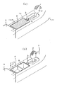
(全体の概要)図1において、車室内の前側には、不図示の運転席と助手席との間にセンターコンソール1が配設されている。センターコンソール1上には、シフトレバー2が前側に設けられ、その後方に可倒式のスイッチ3と、上開口した収納体4と、更に後方に位置して一段高くなったアームレスト5とが設けられている。ここで、収納体4は、図1(a)の蓋閉状態でその上開口が摺動式の蓋体6によって塞がれてセンターコンソールの外観を保っている。また、収納体4は、図1(b)の蓋開状態に示されるようにスイッチ3をオン側に倒すと、蓋体6が後述する駆動装置20を介して自動的に開き方向に摺動される。蓋開状態では、収納体4の内部が露出され、乗員が各種物品や容器類を内部に区画されている空間8や9に出し入れ可能となる。
(Overall Outline) In FIG. 1, a center console 1 is disposed between a driver seat (not shown) and a passenger seat on the front side of the passenger compartment. On the center console 1, a shift lever 2 is provided on the front side, and a retractable switch 3 on the rear side, a
(収納体)この収納部4は、図2及び図3に示されるように、垂直面である前壁4a、略U形の湾曲面である後壁4b、両側壁4c及び底壁4dにて前後に長い概略矩形立体として区画形成されている。内部は、区画壁4eにより前空間8及び後空間9に区画されるとともに、後壁4bの下側に駆動装置用のメカ室10を区画形成している。後壁4bには、湾曲上側に窓12が設けられている。この窓12は左右中間に位置して略矩形穴となっている。メカ室10は、窓12から上へ開口されているとともに側面も開口されており、駆動装置20がその側面の開口から内部に配設される。また、各側壁4c及び後壁4bの両縁にはガイド溝11が対向した状態に設けられている。両ガイド溝11は、断面略凹状で、前壁4a側から後壁4bの手前までが略直線部11aとして延び、続いて後壁4bに沿って下向きに略渦巻き状ないしは略円弧状に形成された湾曲部11bとなっている。
(Storage body) As shown in FIGS. 2 and 3, the
(蓋体)この蓋体6は、図3及び図4から分かるように、1個の先端側連結体7Aと、それ以外の多数の連結体7とで構成され、収納体4の上開口を覆う長さとなっている。このうち、各連結体7は、ABS等の硬質樹脂成形品であり、図6及び図7に示されているように、収納体4の両側壁4c間に対応した横に長い片状をなしている。また、各連結体7は、前端7aの両側に突設された軸部15と、後端7bの両側部分に設けられて軸部15と嵌合可能な凹部16と、裏面側で左右中間部に設けられている凹凸17aを等間隔に形成したラック部17とを一体に有している。軸部15は、前端7aの両内側より両側端へ向けて突出されている。凹部16は、凹部を区画している上縁部分16aが下縁部分16bより張り出すよう形成され、図7(b)や(c)のごとく相手側の軸部15を嵌合した状態で該軸部15の嵌合部分を上縁部分16aの張り出し部で目視不能に覆うよう工夫されている。
(Cover body) As can be seen from FIG. 3 and FIG. 4, the
また、この構造では、上縁部分16が連結体7同士を平面状から外側へ不用意に回動されないよう規制する。このため、連結体7同士は、図7(b)の平面状から図7(c)の内側つまりハ形方向にのみ回動可能となる。また、この例では、連結体7同士が一方連結体側ラック部17の外側凸17aと他方連結体側ラック部17の外側凸17aとの角度設定により角度θ=約30度だけ回動されるよう設定されている。
Further, in this structure, the
これに対し、連結体7Aは、ABS等の硬質樹脂成形品であり、図3及び図4から推察されるように、連結体7と同様に横に長い片状をなし、連結体7に比べて、軸部15及びラック部17を欠如し、後端の両側部分に設けられている凹部16と、上面に設けられた凹状の引手7cとを一体に有している。以上の連結体7及び連結体7Aには、必要に応じて木目等の加飾処理が上面に施される。
On the other hand, the connecting
(駆動装置)この駆動装置20は、図2〜図5に示されるように、メカ室10に配設されており、上述したスイッチ3によりオン−オフされるDCモータ21と、モータ21で回動されるウオームギア22と、ウオームギア22に噛み合うギア23と、ギア23と同軸に枢支されて一体に回動されるギア24と、ギア24と噛み合うギア25と、ギア25と同軸に枢支されて一体に回動されるギア26とを備えている。各ギア22〜25は、モータ21の回動力を減速したり最終のギア26まで伝達する動力伝達機構を構成している。ギア26は、本発明の回転体に相当しており、収納体側の後壁4bに設けた上側の窓12を介して蓋体6(連結体7)側のラック部17と噛み合うよう枢支されている。なお、図面上は、各ギア23〜26を枢支する部材などを省略している。また、量産時には、モータ及び各ギアをユニット化した状態でメカ室10に組み込まれる。それらは必要に応じて設計される。
(Drive Device) As shown in FIGS. 2 to 5, the
(主作動)以上の蓋体の駆動構造では、蓋閉状態で、スイッチ3を一方側に倒すと、蓋体6が図1(b)のごとく駆動装置20を介して自動的に開き方向、つまり両ガイド溝11の直線部11aから湾曲部11bへ摺動されて蓋開状態となる。蓋開状態では、収納体4の内部が露出され、乗員が各種物品や容器類を内部に区画されている空間8や9に出し入れ可能となる。また、蓋体6は、蓋開状態で、スイッチ3を他方側に倒すと、図1(a)のごとく駆動装置20を介して自動的に閉じ方向、つまり両ガイド溝11の湾曲部11bから直線部11aへ摺動されて蓋閉状態となる。このような駆動構造では、例えば、スイッチ3が中立である起立位置にあるとき、回転体であるギア26がアイドル状態に切り替えられ、蓋体6が先端側連結体7Aの凹状の引手7cを利用して、人手によっても開閉操作可能になるよう構成される。
(Main operation) In the above lid driving structure, when the switch 3 is tilted to one side in the lid closed state, the
そして、この駆動構造では、蓋体6が蓋摺動方向に連続して形成させているラック部17を有し、該ラック部17と回転体としてのギア26と、つまりラック・ピニオン方式により開閉されるため、蓋体6の引き込み量を任意に設定できるとともに、蓋体6の引き出し及び引き込みを常に良好に自動で行える。同時に、蓋構造としては、蓋体6が互いに回動可能に連結された複数の連結体7,7Aで構成されているため、例えば、同一形状の連結体7を必要数だけ連結して目的の蓋体を簡単に形成できる。また、湾曲変形時に受ける蓋体6の応力を連結体7,7同士の連結部、つまり軸部15と凹部16との嵌合部で充分吸収でき、その結果、従来のごとく外面の加飾部が歪むというような虞を解消でき、しかも蓋体6のガイド溝11に沿った摺動特性としては湾曲部11bの曲率に関わらず、軸部15と凹部16との嵌合部で湾曲部通過時の摩擦抵抗を吸収したり減じて常に良好に維持できる。
In this drive structure, the
(変形例)図8の変形例は、図4との対比より明らかなように、上記した回転体としてのギア26として、つまり蓋体6のラック部17と噛み合うギア27,28を複数個で構成するとともに、各ギア27,28を共通のギア26Aで回動するようにした例である。この場合は、例えば、蓋体6がラック部17と噛み合う複数のギア27,28で駆動されることで、より良好な状態で摺動されるようにしたり、ギア比の選定で駆動速度を速くすることができる。このように本発明は、請求項で特定される要件を除いて種々変更可能なものである。一例としては、収納体及び蓋体の大きさや形状、駆動装置の配置及びギア構成などについては必要に応じ設計されるものである。
(Modification) In the modification of FIG. 8, as is clear from the comparison with FIG. 4, a plurality of
1…センターコンソール(3はスイッチ、5はアームレスト)
4…収納体(4aは前壁、4bは後壁、4cは側壁、10は空間、12は窓)
6…摺動式蓋体
7,7A…連結体(7aは前端、7bは後端)
11…ガイド溝(11aは直線部、11bは湾曲部)
15…軸部
16…凹部(16aは上縁部分、16bは下縁部分)
17…ラック部(係合部に相当し、17aは凹凸)
20…駆動装置(22はウオームギア、23〜25はギア、27と28はギア)
21…モータ(駆動源)
26,26A…ギア(26aは凹凸)
1 ... Center console (3 is switch, 5 is armrest)
4 ... Storage body (4a is front wall, 4b is rear wall, 4c is side wall, 10 is space, 12 is window)
6 ... Sliding
11 ... Guide groove (11a is a straight part, 11b is a curved part)
15 ...
17 ... Rack part (corresponding to the engaging part, 17a is uneven)
20 ... Drive device (22 is a worm gear, 23 to 25 are gears, 27 and 28 are gears)
21 ... Motor (drive source)
26, 26A ... Gear (26a is uneven)
Claims (4)
前記複数の連結体は、前後端面の一方側に軸部及び他方側に凹部を有し、前記軸部と凹部との嵌合を介して互いに連結されているとともに、前記軸部が連結体両側の内側より両側端へ向けて突出しており該突出部を介し前記ガイド溝内を摺動することを特徴とする蓋体。 Consists of a plurality of connecting bodies that are rotatably connected, each of the connecting bodies having an engaging portion on one surface and continuously forming irregularities in the lid sliding direction at equal intervals. By a rotating body of a driving device provided in the storage body and detachably engaged with the engaging portion in a state of being slidably incorporated along guide grooves provided on both side edges of the body opening In a curved deformable lid that is driven,
The plurality of connecting bodies have a shaft portion on one side of the front and rear end faces and a recess on the other side, and are connected to each other through fitting of the shaft portion and the recess, and the shaft portions are on both sides of the connecting body. A lid that protrudes from the inner side toward both ends and slides in the guide groove through the protruding portion .
前記回転体は外周に凹凸を有するギアであり、前記蓋体の係合部は前記凹凸に噛み合うラック部からなるとともに、前記ガイド溝の直線部に対応した前記ラック部の直線部分で前記ギアと係合して前記蓋体を摺動させることを特徴とする蓋体の駆動構造。 It has an engaging part formed continuously in the lid sliding direction on one side of the lid, and it is slidably incorporated in a guide groove consisting of a straight part and a curved part provided on both sides of the opening of the housing In the drive structure of the lid body that is driven by the rotating body of the drive device that is provided in the storage body and is detachably engaged with the engaging portion ,
The rotating body is a gear having an unevenness on the outer periphery, and the engaging portion of the lid body is formed of a rack portion that meshes with the unevenness, and the linear portion of the rack portion corresponding to the linear portion of the guide groove A lid driving structure characterized by engaging and sliding the lid.
Priority Applications (3)
| Application Number | Priority Date | Filing Date | Title |
|---|---|---|---|
| JP2006085378A JP4808530B2 (en) | 2006-03-27 | 2006-03-27 | Lid and its driving structure |
| PCT/JP2007/053745 WO2007111071A1 (en) | 2006-03-27 | 2007-02-28 | Cover body and its drive structure |
| KR1020070028678A KR100828924B1 (en) | 2006-03-27 | 2007-03-23 | Lid and its driving structure |
Applications Claiming Priority (1)
| Application Number | Priority Date | Filing Date | Title |
|---|---|---|---|
| JP2006085378A JP4808530B2 (en) | 2006-03-27 | 2006-03-27 | Lid and its driving structure |
Publications (2)
| Publication Number | Publication Date |
|---|---|
| JP2007261300A JP2007261300A (en) | 2007-10-11 |
| JP4808530B2 true JP4808530B2 (en) | 2011-11-02 |
Family
ID=38541002
Family Applications (1)
| Application Number | Title | Priority Date | Filing Date |
|---|---|---|---|
| JP2006085378A Expired - Fee Related JP4808530B2 (en) | 2006-03-27 | 2006-03-27 | Lid and its driving structure |
Country Status (3)
| Country | Link |
|---|---|
| JP (1) | JP4808530B2 (en) |
| KR (1) | KR100828924B1 (en) |
| WO (1) | WO2007111071A1 (en) |
Families Citing this family (5)
| Publication number | Priority date | Publication date | Assignee | Title |
|---|---|---|---|---|
| JP5215948B2 (en) | 2009-06-17 | 2013-06-19 | 株式会社ニフコ | Sliding lid structure for containers |
| JP5553194B2 (en) * | 2009-07-22 | 2014-07-16 | カシオ計算機株式会社 | Keyboard instrument lid opening and closing device |
| DE102014226599A1 (en) * | 2014-12-19 | 2016-06-23 | Volkswagen Ag | Arrangement for releasing and closing an opening in an interior trim part of a vehicle |
| CN104590139B (en) * | 2015-02-04 | 2017-08-25 | 重庆长安汽车股份有限公司 | A kind of automobile storage box |
| FR3096009B1 (en) * | 2019-05-15 | 2022-11-18 | Faurecia Interieur Ind | Storage device for a vehicle comprising a tank and a gate mounted to slide relative to the tank |
Family Cites Families (10)
| Publication number | Priority date | Publication date | Assignee | Title |
|---|---|---|---|---|
| ZA80400B (en) * | 1979-03-12 | 1981-05-27 | Minnesota Mining & Mfg | Wire cutting electrical connector |
| JPS6153983A (en) * | 1984-04-20 | 1986-03-18 | 株式会社 清弘エンジニアリング | Drive apparatus of shutter |
| FR2646461B1 (en) * | 1989-04-28 | 1995-05-24 | Marcadet Mobilier | SLIDING CURTAIN WITH ARTICULATED BLADES, PARTICULARLY FOR FURNITURE |
| JPH0728395A (en) * | 1993-07-09 | 1995-01-31 | Dainippon Printing Co Ltd | Map display device |
| JPH06153983A (en) * | 1992-11-30 | 1994-06-03 | Singapore | Monoclonal antibody |
| JP3318828B2 (en) * | 1997-04-01 | 2002-08-26 | 関東自動車工業株式会社 | Automotive console box |
| FR2817900B1 (en) * | 2000-12-08 | 2003-10-03 | Joseph Legeais | PROFILED BLADE FOR CURTAIN CLOSURE |
| FR2857563B1 (en) * | 2003-07-16 | 2007-07-06 | Boulangerie Construction Reali | CABINET FOR PRESERVATION AND CONTROLLED FERMENTATION OF BREADERS |
| JP4307327B2 (en) * | 2004-05-28 | 2009-08-05 | 小島プレス工業株式会社 | Vehicle article storage device |
| JP4602708B2 (en) * | 2004-08-02 | 2010-12-22 | 文化シヤッター株式会社 | Shutter device |
-
2006
- 2006-03-27 JP JP2006085378A patent/JP4808530B2/en not_active Expired - Fee Related
-
2007
- 2007-02-28 WO PCT/JP2007/053745 patent/WO2007111071A1/en active Application Filing
- 2007-03-23 KR KR1020070028678A patent/KR100828924B1/en not_active IP Right Cessation
Also Published As
| Publication number | Publication date |
|---|---|
| JP2007261300A (en) | 2007-10-11 |
| KR20070096904A (en) | 2007-10-02 |
| KR100828924B1 (en) | 2008-05-13 |
| WO2007111071A1 (en) | 2007-10-04 |
Similar Documents
| Publication | Publication Date | Title |
|---|---|---|
| JP4808530B2 (en) | Lid and its driving structure | |
| CN102465631B (en) | The outside handle assembly of tail gate | |
| US20120313382A1 (en) | Opening and closing device for fuel door of vehicle | |
| JP5429556B2 (en) | Vehicle storage device | |
| US8430440B1 (en) | Console door that pivots and stows | |
| JP5262689B2 (en) | Door opening / closing structure and door opening / closing device | |
| JP5755041B2 (en) | Lid opening / closing mechanism and storage device | |
| JP2008174027A (en) | Console box | |
| KR102639724B1 (en) | Glove box apparatus | |
| JP4131740B2 (en) | Switchgear | |
| US5658058A (en) | Floating gear damper | |
| KR101703994B1 (en) | Tray for vehicle | |
| JP4711133B2 (en) | Container holder device | |
| JP5644720B2 (en) | Console Box | |
| JP4239285B2 (en) | Door trim pocket | |
| CN109972938B (en) | Mechanism for opening vehicle door | |
| JP4503473B2 (en) | Vehicle storage structure | |
| JP5153386B2 (en) | Interlocking mechanism of double lid | |
| GB2445741A (en) | Lid assembly for a motor vehicle storage cavity | |
| JP2007099180A (en) | Vehicular storage device | |
| JP5322613B2 (en) | Lid movable device | |
| JP6633441B2 (en) | Door protector structure | |
| KR102088496B1 (en) | Door trim | |
| JP3777370B2 (en) | Air outlet device for vehicles | |
| CN215621298U (en) | Push-pull toggle type air volume control mechanism of automobile air outlet |
Legal Events
| Date | Code | Title | Description |
|---|---|---|---|
| A621 | Written request for application examination |
Free format text: JAPANESE INTERMEDIATE CODE: A621 Effective date: 20080930 |
|
| A131 | Notification of reasons for refusal |
Free format text: JAPANESE INTERMEDIATE CODE: A131 Effective date: 20110610 |
|
| A521 | Request for written amendment filed |
Free format text: JAPANESE INTERMEDIATE CODE: A523 Effective date: 20110722 |
|
| TRDD | Decision of grant or rejection written | ||
| A01 | Written decision to grant a patent or to grant a registration (utility model) |
Free format text: JAPANESE INTERMEDIATE CODE: A01 Effective date: 20110811 |
|
| A01 | Written decision to grant a patent or to grant a registration (utility model) |
Free format text: JAPANESE INTERMEDIATE CODE: A01 |
|
| A61 | First payment of annual fees (during grant procedure) |
Free format text: JAPANESE INTERMEDIATE CODE: A61 Effective date: 20110817 |
|
| FPAY | Renewal fee payment (event date is renewal date of database) |
Free format text: PAYMENT UNTIL: 20140826 Year of fee payment: 3 |
|
| R150 | Certificate of patent or registration of utility model |
Free format text: JAPANESE INTERMEDIATE CODE: R150 Ref document number: 4808530 Country of ref document: JP Free format text: JAPANESE INTERMEDIATE CODE: R150 |
|
| R250 | Receipt of annual fees |
Free format text: JAPANESE INTERMEDIATE CODE: R250 |
|
| R250 | Receipt of annual fees |
Free format text: JAPANESE INTERMEDIATE CODE: R250 |
|
| R250 | Receipt of annual fees |
Free format text: JAPANESE INTERMEDIATE CODE: R250 |
|
| R250 | Receipt of annual fees |
Free format text: JAPANESE INTERMEDIATE CODE: R250 |
|
| R250 | Receipt of annual fees |
Free format text: JAPANESE INTERMEDIATE CODE: R250 |
|
| R250 | Receipt of annual fees |
Free format text: JAPANESE INTERMEDIATE CODE: R250 |
|
| R250 | Receipt of annual fees |
Free format text: JAPANESE INTERMEDIATE CODE: R250 |
|
| R250 | Receipt of annual fees |
Free format text: JAPANESE INTERMEDIATE CODE: R250 |
|
| LAPS | Cancellation because of no payment of annual fees |